EP1745539B1 - Bobine pourvue d'une douille de contact pour connexion electrique - Google Patents
Bobine pourvue d'une douille de contact pour connexion electrique Download PDFInfo
- Publication number
- EP1745539B1 EP1745539B1 EP05734855.9A EP05734855A EP1745539B1 EP 1745539 B1 EP1745539 B1 EP 1745539B1 EP 05734855 A EP05734855 A EP 05734855A EP 1745539 B1 EP1745539 B1 EP 1745539B1
- Authority
- EP
- European Patent Office
- Prior art keywords
- sleeve
- coil
- winding wire
- region
- cable
- Prior art date
- Legal status (The legal status is an assumption and is not a legal conclusion. Google has not performed a legal analysis and makes no representation as to the accuracy of the status listed.)
- Expired - Lifetime
Links
Images


Classifications
-
- H—ELECTRICITY
- H01—ELECTRIC ELEMENTS
- H01F—MAGNETS; INDUCTANCES; TRANSFORMERS; SELECTION OF MATERIALS FOR THEIR MAGNETIC PROPERTIES
- H01F5/00—Coils
- H01F5/04—Arrangements of electric connections to coils, e.g. leads
-
- H—ELECTRICITY
- H01—ELECTRIC ELEMENTS
- H01R—ELECTRICALLY-CONDUCTIVE CONNECTIONS; STRUCTURAL ASSOCIATIONS OF A PLURALITY OF MUTUALLY-INSULATED ELECTRICAL CONNECTING ELEMENTS; COUPLING DEVICES; CURRENT COLLECTORS
- H01R4/00—Electrically-conductive connections between two or more conductive members in direct contact, i.e. touching one another; Means for effecting or maintaining such contact; Electrically-conductive connections having two or more spaced connecting locations for conductors and using contact members penetrating insulation
- H01R4/10—Electrically-conductive connections between two or more conductive members in direct contact, i.e. touching one another; Means for effecting or maintaining such contact; Electrically-conductive connections having two or more spaced connecting locations for conductors and using contact members penetrating insulation effected solely by twisting, wrapping, bending, crimping, or other permanent deformation
- H01R4/18—Electrically-conductive connections between two or more conductive members in direct contact, i.e. touching one another; Means for effecting or maintaining such contact; Electrically-conductive connections having two or more spaced connecting locations for conductors and using contact members penetrating insulation effected solely by twisting, wrapping, bending, crimping, or other permanent deformation by crimping
- H01R4/187—Electrically-conductive connections between two or more conductive members in direct contact, i.e. touching one another; Means for effecting or maintaining such contact; Electrically-conductive connections having two or more spaced connecting locations for conductors and using contact members penetrating insulation effected solely by twisting, wrapping, bending, crimping, or other permanent deformation by crimping combined with soldering or welding
-
- H—ELECTRICITY
- H01—ELECTRIC ELEMENTS
- H01F—MAGNETS; INDUCTANCES; TRANSFORMERS; SELECTION OF MATERIALS FOR THEIR MAGNETIC PROPERTIES
- H01F5/00—Coils
- H01F5/02—Coils wound on non-magnetic supports, e.g. formers
-
- H—ELECTRICITY
- H01—ELECTRIC ELEMENTS
- H01R—ELECTRICALLY-CONDUCTIVE CONNECTIONS; STRUCTURAL ASSOCIATIONS OF A PLURALITY OF MUTUALLY-INSULATED ELECTRICAL CONNECTING ELEMENTS; COUPLING DEVICES; CURRENT COLLECTORS
- H01R13/00—Details of coupling devices of the kinds covered by groups H01R12/70 or H01R24/00 - H01R33/00
- H01R13/40—Securing contact members in or to a base or case; Insulating of contact members
- H01R13/405—Securing in non-demountable manner, e.g. moulding, riveting
- H01R13/41—Securing in non-demountable manner, e.g. moulding, riveting by frictional grip in grommet, panel or base
Definitions
- the invention relates to a coil, a brake and an electric motor.
- Coil carriers for winding wire wound coils are well known.
- a brake coil with a center tap ( Fig. 4 , Reference numeral 6) is known, which can be used as a brake for an electric motor.
- the disadvantage here is that the production is complicated and expensive. It is important that every additional contact of the winding wire during manufacture causes effort and costs.
- the invention is therefore the object of developing a coil to make them cheaper and easier, in particular velvet contacting.
- This also relates to coils with at least one center tap .
- the object is achieved in the coil according to claim 1 and in the brake according to the claim 8 and in the electric motor according to the features specified in claim 9.
- Essential features of the invention in the coil are that it comprises at least a coil carrier and a winding wire, wherein at least one sleeve is electrically connected to the winding wire, the sleeve establishing an electrical connection between the winding wire and a strand of a cable, wherein the electrical connection belongs to a center tap of the coil, wherein the coil carrier comprises at least one channel which is formed as a pocket, in which the sleeve is inserted and is fastened in a force-locking and / or form-fitting manner, wherein the sleeve comprises one or more deformed regions, wherein the sleeve comprises a first support portion, which is provided as a support and / or guide for the winding wire by the sleeve having a wall portion and bent away from the wall portion first tongues on both sides, which have a cutout in the region of the bend, one side of which as a support acts on which the winding wire is placed and guided, wherein the sleeve deformed at
- the advantage here is that the sleeve allows a cost-effective electrical connection.
- the sleeve itself is manufactured as a cost-effective stamped and bent part made of sheet metal. Since it has deformable regions, winding wire sections or stranded sections can be clamped in by means of these regions, that is to say they can be frictionally connected. By appropriate heating then welded joints can be produced. By means of other deformable areas and other parts of the cable can be clamped and thus a strain relief for the cable with strand realized.
- the sleeve comprises at least a first support region, which is provided as a support and / or guide for the winding wire, wherein the sleeve comprises at least a second, designed as a tongue area, which is deformable for non-positive connection with the winding wire and for producing a Welded connection with the winding wire is providable, wherein the sleeve comprises at least a third portion which is provided for welding connection to the strand of a cable.
- the advantage here is that the winding wire is easily einfädelbar and then comes to rest on the support surface, so it is precisely positioned.
- the threading is so well executed by shaping the sleeve that the winding wire is inserted into the second region, ie in the region of the deformable tongue.
- This is deformable, ie in particular easily pressed against a wall part for clamping, so non-positive connection of the winding wire with the sleeve.
- the clamped winding wire is then quickly and easily welded.
- the welded connection is well protected against stressful forces, because the non-positive connection continues to act and thus relieves the weld joint.
- the sleeve is designed to make an electrical connection between the winding wire and the electric wire or a strand suitable.
- the advantage here is that a conductive metal and a particularly suitable for producing a welded metal is selectable, which is also inexpensive and is produced by means of a stamping and bending process.
- the sleeve is fixed in the coil carrier non-positively and / or positively.
- the sleeve comprises at least one barb, in particular for hooking in the channel.
- the areas are connected to a wall part.
- the advantage here is that the areas are stable rainbowhaltbar means of the wall part.
- the coil comprises a center tap.
- the advantage here is that particularly fast switchable brake are executable.
- the sleeve comprises at least a fourth region, as a trained as a tongue area, which is for non-positive connection with a cable, in particular with the insulation of the cable, deformable .
- the coating of the winding wire during manufacture of a welded connection is removable at least in the region of the electrical contact point, in particular by the heating occurring during the production of the welded connection.
- the coil comprises potting compound, in particular in the region of the channel and / or the winding.
- potting compound in particular in the region of the channel and / or the winding.
- the coil carrier comprises a holder for winding wire and / or cable.
- the advantage here is that the holder is already produced in the injection molding of the bobbin and thus no further operation is necessary.
- the brake coil of the brake is designed in the manner of the aforementioned coil.
- the advantage here is that a cost-effective brake coil can be realized even with center tap.
- three sleeves are necessary with which litz wire is tapped at the beginning, in the middle and at the end of the winding wire winding of the coil.
- the electric motor comprises a brake with a brake coil or a coil, as described above. , Is of advantage that the electric motor with little effort and cost is manufacturable and in the manufacture a high automatable ungs grad achievable.
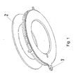
- a coil carrier 2 is shown in the FIG. 1 . It is advantageously manufactured as a plastic injection molded part and has a holder 7 as attachment for an outgoing cable.
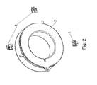
- FIG. 2 three sleeves 1 are shown, which are insertable at three locations on the circumference in the bobbin.
- FIG. 3 In the FIG. 3 is a cable 3, comprising electrically conductive wire and insulation, shown, which is insertable into the lower part of the sleeve 1, before they are inserted into the coil carrier.
- FIG. 4 the three cables 3 are shown, which are connected to corresponding sleeves 1, before they are inserted into the bobbin 1.
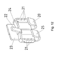
- FIG. 5 shows the connected to the sleeve 1 cable 3 increases, wherein FIG. 12 the sleeve 1 itself enlarged without cable represents.
- the left bending part 25 is deformed such that the insulation is fixed to the sleeve 1 and thus a strain relief for the right part of the cable is provided.
- the right bending part 20 is electrically conductively connected to the strand of the cable 3, in particular welded.
- FIG. 6 shows the bobbin 2, wherein the cables 1 connected to the cables are inserted.
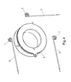
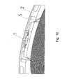
- FIG. 7 shows the channel 4, in which the sleeves 1 are inserted, more clearly.
- the channel 4 is designed as a bag.
- FIG. 8 shows how FIG. 7 the inserted sleeves, wherein the cables are guided through the eyelet of the holder 7.
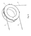
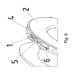
- FIG. 9 shows a holder 6 for fixing a first end of a winding wire 5, which is guided over the sleeve 1 and rests on the tongues 24 of the sleeve 1, wherein FIG. 12 the sleeve 1 itself enlarged without cable represents.
- FIG. 10 shows a guided over the sleeve 1 winding wire. 5
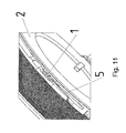
- FIG. 11 shows the sleeve 1 in the inserted into the bobbin state.
- the sleeve is shown larger than in FIG. 13a ,
- the sleeve is designed as a stamped and bent part and has a wall portion 23 on which a tongue 22, bent away.
- FIG. 13b In the FIG. 13b is shown how the bending state of the tongues 20,25 is when a cable is inserted with its insulation coming from the left and the insulation with the left tongue 25 is fixed. This fixation causes a strain relief for the stripped right end of the cable, so bare strand. This strand piece is compressed with the tongue 20 and then electrically welded. Thus, a very good electrically conductive connection of the strand is created with the sleeve, which tolerates high mechanical loads due to the strain relief.
- FIG. 13c the bending state of the tongue 22 is shown, which fixes the winding wire and with which the winding wire is welded.
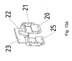
- FIG. 13d shows in contrast to FIG. 13b the cable feed from the right, thus the tongue 20 is less bent to fix the cable with insulation and the tongue 25 is bent more to fix the strand of the stripped cable end piece.
- Figure 14a and 14b show the bobbin 2 in different orientations, wherein the executed as a pocket channel 4 is shown and also the slot 9 for insertion of the Winding wire is shown. The winding wire is then wound and led at the end over a corner and the sleeve 1 to the holder 6, as in FIG. 9 clearly shown.
- the holder 6 can also be omitted on the bobbin and instead be provided on the tool.
- the channel is potted at the end of the production with a potting compound.
- the coil is particularly advantageous as a brake coil an electromagnetically actuated brake providable.
- This brake can advantageously be used in an electric motor and integrated.
- FIGS. 15 to 27 An embodiment of the invention is in the FIGS. 15 to 27 shown.
- FIG. 15 shows the developed sleeve 101 with the wall portion 123.
- the first tongues 124 have in this embodiment positioning function for the winding wire.
- the winding wire 105 is held between the wall portion 123 and the first tongues 124. In this case it rests on the bearing surfaces 125 for winding wire.
- the winding wire is pressed with the second tongue 122 to the wall portion 123 and is welded there to make the electrical connection.
- this course of the wire is shown exactly.
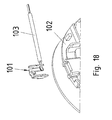
- the wall portions 120 are provided for connection to stripped cable 103 comprising strand and insulation.
- the stranded wires are there welded or soldered to a wall portion 120, as in FIG. 18 is shown in more detail.
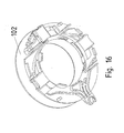
- FIG. 16 shows the bobbin 102, in which up to three sleeves 101 are insertable.
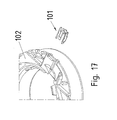
- FIG. 17 the sleeve 101 before insertion into the coil carrier 102nd
- FIG. 18 shows the connection with the cable 103 with insulation, wherein the stripped end portions of the cable 103 are welded.
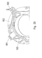
- FIG. 19 shows the inserted into the bobbin 102 sleeve 101 and inserted into a channel cable 103rd
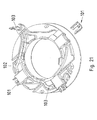
- FIG. 20 shows an associated different perspective.
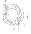
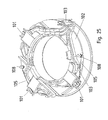
- FIG. 21 shows the bobbin with two inserted sleeves 101 and a sleeve 101 before insertion.
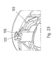
- FIG. 22 shows the winding wire 105, which is attached to a bracket 108 and runs over the bearing surfaces 125 of the sleeve. In between, the winding wire 105 is inserted into the still open second tongue 122.
- FIG. 23 and 24 each shows a different view.
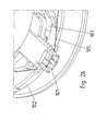
- FIG. 25 shows the bobbin 102 with three inserted sleeves 101, wherein the second tongue 122 is closed, that is pressed against the wall portion 123. In this way, the winding wire is easy to weld.
- FIG. 26 shows an enlarged section.
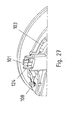
- FIG. 27 shows a different perspective.
Landscapes
- Engineering & Computer Science (AREA)
- Power Engineering (AREA)
- Insulation, Fastening Of Motor, Generator Windings (AREA)
- Connections Effected By Soldering, Adhesion, Or Permanent Deformation (AREA)
- Coils Or Transformers For Communication (AREA)
- Electromagnets (AREA)
Claims (9)
- Bobine, comprenant au moins un porte-bobine (102) et un fil de bobinage (105),
au moins une douille (101) étant reliée électriquement au fil de bobinage (105),
la douille (101) établissant une liaison électrique entre le fil de bobinage (105) et un toron d'un câble (103),
la liaison électrique appartenant à une prise médiane de la bobine,
le porte-bobine (102) comportant au moins un canal qui est réalisé sous la forme d'un évidement dans lequel la douille (101) est introduite et fixée par conjugaison de forces et/ou complémentarité de formes,
la douille (101) comportant une ou plusieurs zones déformées,
la douille (101) comportant une première zone d'appui (125) qui est prévue comme appui et/ou guide pour le fil de bobinage (105), la douille (101) présentant une partie de paroi (123) et présentant de chaque côté des premières languettes (124) courbées à l'opposé de la partie de paroi, lesquelles ont une découpe dans la zone de la courbure, dont un côté sert d'appui (125) sur lequel le fil de bobinage (105) est posé et guidé,
la douille (101) comportant au moins une deuxième zone déformée réalisée sous la forme d'une deuxième languette (122) pour la liaison électrique et par conjugaison de forces avec le fil de bobinage (105), avec laquelle le fil de bobinage (105) est relié par conjugaison de forces et soudé,
la douille (101) comportant au moins une troisième zone (120) dans la partie de paroi (123), à laquelle le toron d'un câble (103) est relié par soudage,
la douille (101) étant réalisée sous la forme d'une pièce découpée et pliée. - Bobine selon la revendication 1,
caractérisée ce que
la douille (101) comporte au moins un crochet (21) pour s'accrocher dans le canal (4). - Bobine selon au moins l'une des revendications précédentes,
caractérisée en ce que
la troisième zone de la douille est aussi reliée par conjugaison de forces au toron (103). - Bobine selon au moins l'une des revendications précédentes,
caractérisée en ce que
la douille (101) comporte au moins une quatrième zone réalisée sous la forme d'une languette (25) qui peut être déformée pour la liaison par conjugaison de forces avec un câble, en particulier avec l'isolation du câble. - Bobine selon au moins l'une des revendications précédentes,
caractérisée en ce que
la couche de vernis du fil de bobinage est éliminée au moins dans la zone du contact électrique par la chaleur produite lors de la réalisation de la soudure. - Bobine selon au moins l'une des revendications précédentes,
caractérisée en ce que
la bobine comporte une masse de scellement, en particulier dans la zone du canal et/ou du bobinage. - Bobine selon au moins l'une des revendications précédentes,
caractérisée en ce que
le porte-bobine (2) comprend un support (6) pour le fil de bobinage (5) et/ou le câble. - Frein
dans lequel une bobine selon au moins l'une des revendications précédentes est prévue comme bobine de frein dans un électro-aimant. - Moteur électrique,
caractérisée en ce que
le moteur électrique comprend un frein selon la revendication 8.
Applications Claiming Priority (2)
| Application Number | Priority Date | Filing Date | Title |
|---|---|---|---|
| DE102004022254A DE102004022254B3 (de) | 2004-05-04 | 2004-05-04 | Spule |
| PCT/EP2005/003515 WO2005109606A1 (fr) | 2004-05-04 | 2005-04-04 | Bobine pourvue d'une douille de contact pour connexion electrique |
Publications (2)
| Publication Number | Publication Date |
|---|---|
| EP1745539A1 EP1745539A1 (fr) | 2007-01-24 |
| EP1745539B1 true EP1745539B1 (fr) | 2015-06-10 |
Family
ID=34625853
Family Applications (1)
| Application Number | Title | Priority Date | Filing Date |
|---|---|---|---|
| EP05734855.9A Expired - Lifetime EP1745539B1 (fr) | 2004-05-04 | 2005-04-04 | Bobine pourvue d'une douille de contact pour connexion electrique |
Country Status (9)
| Country | Link |
|---|---|
| US (1) | US7839252B2 (fr) |
| EP (1) | EP1745539B1 (fr) |
| JP (1) | JP4886677B2 (fr) |
| CN (1) | CN1950987B (fr) |
| AU (1) | AU2005241611B2 (fr) |
| BR (1) | BRPI0509618B1 (fr) |
| CA (1) | CA2561197C (fr) |
| DE (1) | DE102004022254B3 (fr) |
| WO (1) | WO2005109606A1 (fr) |
Families Citing this family (14)
| Publication number | Priority date | Publication date | Assignee | Title |
|---|---|---|---|---|
| DE102006034049B4 (de) * | 2006-07-20 | 2014-08-07 | Sew-Eurodrive Gmbh & Co Kg | Elektromagnetisch betätigbare Bremse oder Kupplung mit Lüftspule, Verfahren zum Betreiben derselben und Antrieb |
| DE102008034413B4 (de) | 2008-07-23 | 2020-01-09 | Sew-Eurodrive Gmbh & Co Kg | Kontakthaken und elektromagnetisch betätigbare Bremse |
| US8602658B2 (en) * | 2010-02-05 | 2013-12-10 | Baker Hughes Incorporated | Spoolable signal conduction and connection line and method |
| DE102010014860B4 (de) | 2010-04-13 | 2018-12-20 | Sew-Eurodrive Gmbh & Co Kg | Spule und Bremse |
| GB2485205B (en) * | 2010-11-05 | 2016-08-17 | Rolls Royce Plc | A superconductor device |
| US9151921B2 (en) * | 2014-02-13 | 2015-10-06 | Siemens Energy, Inc. | Apparatus for making uniform optical fiber bundles in power generators |
| DE102015009620A1 (de) | 2014-09-08 | 2016-03-10 | Sew-Eurodrive Gmbh & Co Kg | Elektromotor mit einer aus Wicklungsdrahtabschnitten ausgeführten Statorwicklung |
| CN104538815B (zh) * | 2014-12-02 | 2016-08-24 | 国网河南省电力公司洛阳供电公司 | 一种压接管的校正装置 |
| CN106297315A (zh) * | 2016-08-26 | 2017-01-04 | 杭州研智科技有限公司 | 一种停车场车位占用感应装置 |
| CN109399401A (zh) * | 2018-11-29 | 2019-03-01 | 刘禄军 | 一种卷线装置 |
| CN116246871B (zh) * | 2023-05-10 | 2023-08-01 | 四川富美高电子有限公司 | 一种变压器骨架 |
| DE102024111216A1 (de) * | 2023-05-11 | 2024-11-14 | Sew-Eurodrive Gmbh & Co. Kg | Drahtführungselement, Bremse zum Abbremsen einer Welle und Bremsmotor mit Bremse |
| WO2026046615A1 (fr) * | 2024-08-26 | 2026-03-05 | Sew-Eurodrive Gmbh & Co Kg | Procédé de fabrication d'un système de freinage, système de freinage et moteur électrique équipé d'un système de freinage |
| CN119306065A (zh) * | 2024-11-20 | 2025-01-14 | 盐城中大三协汽车装备有限公司 | 一种全自动自洁式卷管器 |
Citations (1)
| Publication number | Priority date | Publication date | Assignee | Title |
|---|---|---|---|---|
| US4720646A (en) * | 1985-12-03 | 1988-01-19 | Mitsubishi Denki Kabushiki Kaisha | Connection terminal assembly for stator coil |
Family Cites Families (36)
| Publication number | Priority date | Publication date | Assignee | Title |
|---|---|---|---|---|
| US559046A (en) * | 1896-04-28 | Stirrup | ||
| US3461413A (en) * | 1966-11-10 | 1969-08-12 | Teletype Corp | Shielded electrical inductor component |
| DE2236241A1 (de) * | 1972-07-24 | 1974-02-07 | Siemens Ag | Spulenkoerper |
| CH642765A5 (de) * | 1979-05-31 | 1984-04-30 | Landis & Gyr Ag | Spule mit einem spulentopf mit anschlussfahnen fuer elektrische geraete. |
| DE7923585U1 (de) * | 1979-08-18 | 1980-08-07 | Harting Elektronik Gmbh, 4992 Espelkamp | Elektrische spule |
| DE8026597U1 (de) * | 1980-10-04 | 1981-01-29 | Licentia Patent-Verwaltungs-Gmbh, 6000 Frankfurt | In eine der beiden zur isolierung der stirnflaechen des staenderblechpakets elektrischer maschinen mit ausgepraegten polen dienenden endscheiben eingesetzte anschlussklemmen |
| US4588973A (en) * | 1981-07-30 | 1986-05-13 | Emhart Industries, Inc. | Coil bobbin having novel means for terminating fine wires |
| JPS5891871A (ja) * | 1981-11-26 | 1983-05-31 | 日本エステル株式会社 | 詰綿用ポリエステル繊維油剤 |
| JPS5891871U (ja) * | 1981-12-17 | 1983-06-21 | 三菱電機株式会社 | 接続端子 |
| DE8234030U1 (de) * | 1982-12-03 | 1984-05-17 | Robert Bosch Gmbh, 7000 Stuttgart | Elektrische spule mit eisenkern |
| DE3407758A1 (de) * | 1984-03-02 | 1985-09-12 | Standard Elektrik Lorenz Ag, 7000 Stuttgart | Automatengerechter spulenkoerper fuer elektrische geraete |
| US4633110A (en) | 1985-03-20 | 1986-12-30 | Rotron, Inc. | Motor with stator on printed circuit assembly |
| JPS61237375A (ja) * | 1985-04-11 | 1986-10-22 | アンプ インコ−ポレ−テツド | レセプタクル端子 |
| JPS62165764A (ja) * | 1986-01-18 | 1987-07-22 | Matsushita Electric Ind Co Ltd | カ−トリツジデイスク装置 |
| JPS62170470A (ja) * | 1986-01-22 | 1987-07-27 | Hitachi Ltd | ハフニウム基合金 |
| JPH0424783Y2 (fr) * | 1986-04-10 | 1992-06-11 | ||
| JPS62170470U (fr) * | 1986-04-18 | 1987-10-29 | ||
| DE3613294A1 (de) * | 1986-04-19 | 1987-10-22 | Sew Eurodrive Gmbh & Co | Bremse fuer einen motor |
| US4728916A (en) * | 1986-06-05 | 1988-03-01 | Lectron Products, Inc. | Solenoid operated fluid control valve |
| JPS6476704A (en) * | 1987-09-17 | 1989-03-22 | Aisin Seiki | Solenoid device |
| JPH0218980A (ja) * | 1988-07-07 | 1990-01-23 | Sumitomo Electric Ind Ltd | ダイヤモンドレーザ素子の作製方法 |
| JPH0218980U (fr) * | 1988-07-25 | 1990-02-08 | ||
| JPH0625945Y2 (ja) * | 1988-08-05 | 1994-07-06 | 東洋電装株式会社 | エンジンの点火コイル |
| JPH033704A (ja) * | 1989-05-31 | 1991-01-09 | Tsugami Corp | 回転磁気ヘッド用固定シリンダの加工方法 |
| JPH03112113A (ja) * | 1989-09-26 | 1991-05-13 | Matsushita Electric Works Ltd | コイルの端末処理方法 |
| DE4118166C3 (de) | 1991-06-03 | 1995-10-26 | Siemens Ag | Schweißverfahren zur Verbindung eines Wicklungsdrahtes einer Spule mit einem Anschlußelement und Metall-Hülse zur Anwendung bei diesem Verfahren |
| JPH0595184U (ja) * | 1992-05-22 | 1993-12-24 | 株式会社三協精機製作所 | 電機子 |
| JP3048485B2 (ja) * | 1993-03-15 | 2000-06-05 | 矢崎総業株式会社 | 端子と電線のビーム溶接方法 |
| DE4340638A1 (de) | 1993-11-27 | 1995-06-01 | Bosch Gmbh Robert | Elektrische Verbindungsanordnung |
| JP2965127B2 (ja) * | 1995-03-13 | 1999-10-18 | 協伸工業株式会社 | 基板用接続端子 |
| JPH11234940A (ja) * | 1998-02-16 | 1999-08-27 | Mitsubishi Electric Corp | 電動機用固定子 |
| US6252485B1 (en) * | 1998-07-14 | 2001-06-26 | Ching-Jen Lin | Rotation coil bobbin for picture tube |
| JP4183155B2 (ja) | 2000-01-12 | 2008-11-19 | 東芝キヤリア株式会社 | 電動機 |
| US6633216B2 (en) * | 2001-01-12 | 2003-10-14 | Kelsey-Hayes Company | Self-locating coil assembly |
| JP3952750B2 (ja) * | 2001-11-20 | 2007-08-01 | Nok株式会社 | ソレノイド |
| US6903647B2 (en) * | 2002-05-08 | 2005-06-07 | Kelsey-Hayes Company | Solenoid valve coil having an integrated bobbin and flux ring assembly |
-
2004
- 2004-05-04 DE DE102004022254A patent/DE102004022254B3/de not_active Expired - Lifetime
-
2005
- 2005-04-04 AU AU2005241611A patent/AU2005241611B2/en not_active Expired
- 2005-04-04 BR BRPI0509618-9A patent/BRPI0509618B1/pt active IP Right Grant
- 2005-04-04 WO PCT/EP2005/003515 patent/WO2005109606A1/fr not_active Ceased
- 2005-04-04 CA CA2561197A patent/CA2561197C/fr not_active Expired - Lifetime
- 2005-04-04 JP JP2007511899A patent/JP4886677B2/ja not_active Expired - Lifetime
- 2005-04-04 CN CN200580014127.8A patent/CN1950987B/zh not_active Expired - Lifetime
- 2005-04-04 US US11/579,774 patent/US7839252B2/en active Active
- 2005-04-04 EP EP05734855.9A patent/EP1745539B1/fr not_active Expired - Lifetime
Patent Citations (1)
| Publication number | Priority date | Publication date | Assignee | Title |
|---|---|---|---|---|
| US4720646A (en) * | 1985-12-03 | 1988-01-19 | Mitsubishi Denki Kabushiki Kaisha | Connection terminal assembly for stator coil |
Also Published As
| Publication number | Publication date |
|---|---|
| WO2005109606A1 (fr) | 2005-11-17 |
| JP4886677B2 (ja) | 2012-02-29 |
| AU2005241611B2 (en) | 2009-11-12 |
| BRPI0509618A (pt) | 2007-09-18 |
| CN1950987A (zh) | 2007-04-18 |
| BRPI0509618B1 (pt) | 2018-03-06 |
| CA2561197C (fr) | 2011-01-04 |
| DE102004022254B3 (de) | 2005-06-30 |
| US7839252B2 (en) | 2010-11-23 |
| CN1950987B (zh) | 2014-07-23 |
| EP1745539A1 (fr) | 2007-01-24 |
| AU2005241611A1 (en) | 2005-11-17 |
| CA2561197A1 (fr) | 2005-11-17 |
| US20070222312A1 (en) | 2007-09-27 |
| JP2007536751A (ja) | 2007-12-13 |
Similar Documents
| Publication | Publication Date | Title |
|---|---|---|
| EP1745539B1 (fr) | Bobine pourvue d'une douille de contact pour connexion electrique | |
| EP1774545B1 (fr) | Support destine a un composant electrique | |
| DE3787514T2 (de) | Kommutator. | |
| EP2837061B1 (fr) | Dispositif de mise en contact pour connecter un conducteur électrique | |
| EP1555865B1 (fr) | Assemblage d'un circuit bouchon avec des composants électroniques discrets et passifs | |
| EP1667285A2 (fr) | Maintien de câble | |
| EP1474814B1 (fr) | Corps de bobine et bobine pour l'assemblage de cartes de circuits imprimes | |
| DE602005002323T2 (de) | Antenne und Funkkommunikationsendgerät mit dieser Antenne | |
| EP2933804B1 (fr) | Composant à induction | |
| EP1182735B1 (fr) | Réglette d'interconnexion électrique | |
| EP2471144B1 (fr) | Ensemble de liaison électrique, notamment de mise en contact électrique d'un câble coaxial multibrin et d'une carte de circuit imprimé, circuiterie et appareil électronique | |
| DE8911461U1 (de) | Anker für einen Elektromotor | |
| DE102010014860B4 (de) | Spule und Bremse | |
| WO1991011818A1 (fr) | Relais electromagnetique | |
| EP0258664A2 (fr) | Unité pour fixer des lignes électriques dans des distributeurs d'installations de télécommunication | |
| DE2752847B2 (de) | Gehäuse mit einem darin angeordneten elektrischen Bauelement | |
| WO1997039496A1 (fr) | Dispositif de raccordement electrique et element de connexion electrique s'utilisant dans un dispositif de raccordement electrique | |
| DE3316456A1 (de) | Spulenkoerper | |
| EP1480290B1 (fr) | Dispositif de contact avec un fil de connexion | |
| DE102021110661B4 (de) | Elektrisches Leiteranschlusselement mit Kontaktfeder | |
| DE10353162A1 (de) | Struktur und Verfahren für die Bearbeitungs des Endes von Flachkabeln | |
| EP2161786A1 (fr) | Elément de raccordement de câble | |
| DE102013208176A1 (de) | Stabkerndrossel | |
| CH699568A1 (de) | Anordnung mit einer Leiterplatte und mindestens einem Stift sowie Verfahren zum Anbringen von Stiften an einer Leiterplatte. | |
| DE19730603A1 (de) | Anschlußklemmeinrichtung |
Legal Events
| Date | Code | Title | Description |
|---|---|---|---|
| PUAI | Public reference made under article 153(3) epc to a published international application that has entered the european phase |
Free format text: ORIGINAL CODE: 0009012 |
|
| 17P | Request for examination filed |
Effective date: 20061204 |
|
| AK | Designated contracting states |
Kind code of ref document: A1 Designated state(s): AT BE BG CH CY CZ DE DK EE ES FI FR GB GR HU IE IS IT LI LT LU MC NL PL PT RO SE SI SK TR |
|
| 17Q | First examination report despatched |
Effective date: 20070215 |
|
| RIN1 | Information on inventor provided before grant (corrected) |
Inventor name: LAMBLING, JEAN-PIERRE Inventor name: FLOERCHINGER, GERHARD Inventor name: CRIQUI, LAURENT Inventor name: SCHUELER, GERD Inventor name: HEINRICH, PASCAL |
|
| DAX | Request for extension of the european patent (deleted) | ||
| GRAP | Despatch of communication of intention to grant a patent |
Free format text: ORIGINAL CODE: EPIDOSNIGR1 |
|
| INTG | Intention to grant announced |
Effective date: 20150123 |
|
| GRAS | Grant fee paid |
Free format text: ORIGINAL CODE: EPIDOSNIGR3 |
|
| GRAA | (expected) grant |
Free format text: ORIGINAL CODE: 0009210 |
|
| AK | Designated contracting states |
Kind code of ref document: B1 Designated state(s): AT BE BG CH CY CZ DE DK EE ES FI FR GB GR HU IE IS IT LI LT LU MC NL PL PT RO SE SI SK TR |
|
| REG | Reference to a national code |
Ref country code: GB Ref legal event code: FG4D Free format text: NOT ENGLISH |
|
| REG | Reference to a national code |
Ref country code: CH Ref legal event code: EP |
|
| REG | Reference to a national code |
Ref country code: AT Ref legal event code: REF Ref document number: 731256 Country of ref document: AT Kind code of ref document: T Effective date: 20150715 |
|
| REG | Reference to a national code |
Ref country code: DE Ref legal event code: R096 Ref document number: 502005014813 Country of ref document: DE |
|
| REG | Reference to a national code |
Ref country code: IE Ref legal event code: FG4D Free format text: LANGUAGE OF EP DOCUMENT: GERMAN |
|
| PG25 | Lapsed in a contracting state [announced via postgrant information from national office to epo] |
Ref country code: ES Free format text: LAPSE BECAUSE OF FAILURE TO SUBMIT A TRANSLATION OF THE DESCRIPTION OR TO PAY THE FEE WITHIN THE PRESCRIBED TIME-LIMIT Effective date: 20150610 Ref country code: LT Free format text: LAPSE BECAUSE OF FAILURE TO SUBMIT A TRANSLATION OF THE DESCRIPTION OR TO PAY THE FEE WITHIN THE PRESCRIBED TIME-LIMIT Effective date: 20150610 Ref country code: FI Free format text: LAPSE BECAUSE OF FAILURE TO SUBMIT A TRANSLATION OF THE DESCRIPTION OR TO PAY THE FEE WITHIN THE PRESCRIBED TIME-LIMIT Effective date: 20150610 |
|
| REG | Reference to a national code |
Ref country code: NL Ref legal event code: MP Effective date: 20150610 |
|
| PG25 | Lapsed in a contracting state [announced via postgrant information from national office to epo] |
Ref country code: GR Free format text: LAPSE BECAUSE OF FAILURE TO SUBMIT A TRANSLATION OF THE DESCRIPTION OR TO PAY THE FEE WITHIN THE PRESCRIBED TIME-LIMIT Effective date: 20150911 Ref country code: BG Free format text: LAPSE BECAUSE OF FAILURE TO SUBMIT A TRANSLATION OF THE DESCRIPTION OR TO PAY THE FEE WITHIN THE PRESCRIBED TIME-LIMIT Effective date: 20150910 |
|
| PG25 | Lapsed in a contracting state [announced via postgrant information from national office to epo] |
Ref country code: EE Free format text: LAPSE BECAUSE OF FAILURE TO SUBMIT A TRANSLATION OF THE DESCRIPTION OR TO PAY THE FEE WITHIN THE PRESCRIBED TIME-LIMIT Effective date: 20150610 |
|
| REG | Reference to a national code |
Ref country code: FR Ref legal event code: PLFP Year of fee payment: 12 |
|
| PG25 | Lapsed in a contracting state [announced via postgrant information from national office to epo] |
Ref country code: IS Free format text: LAPSE BECAUSE OF FAILURE TO SUBMIT A TRANSLATION OF THE DESCRIPTION OR TO PAY THE FEE WITHIN THE PRESCRIBED TIME-LIMIT Effective date: 20151010 Ref country code: CZ Free format text: LAPSE BECAUSE OF FAILURE TO SUBMIT A TRANSLATION OF THE DESCRIPTION OR TO PAY THE FEE WITHIN THE PRESCRIBED TIME-LIMIT Effective date: 20150610 Ref country code: RO Free format text: LAPSE BECAUSE OF NON-PAYMENT OF DUE FEES Effective date: 20150610 Ref country code: PL Free format text: LAPSE BECAUSE OF FAILURE TO SUBMIT A TRANSLATION OF THE DESCRIPTION OR TO PAY THE FEE WITHIN THE PRESCRIBED TIME-LIMIT Effective date: 20150610 Ref country code: SK Free format text: LAPSE BECAUSE OF FAILURE TO SUBMIT A TRANSLATION OF THE DESCRIPTION OR TO PAY THE FEE WITHIN THE PRESCRIBED TIME-LIMIT Effective date: 20150610 Ref country code: PT Free format text: LAPSE BECAUSE OF FAILURE TO SUBMIT A TRANSLATION OF THE DESCRIPTION OR TO PAY THE FEE WITHIN THE PRESCRIBED TIME-LIMIT Effective date: 20151012 |
|
| REG | Reference to a national code |
Ref country code: DE Ref legal event code: R097 Ref document number: 502005014813 Country of ref document: DE |
|
| PLBE | No opposition filed within time limit |
Free format text: ORIGINAL CODE: 0009261 |
|
| STAA | Information on the status of an ep patent application or granted ep patent |
Free format text: STATUS: NO OPPOSITION FILED WITHIN TIME LIMIT |
|
| PG25 | Lapsed in a contracting state [announced via postgrant information from national office to epo] |
Ref country code: DK Free format text: LAPSE BECAUSE OF FAILURE TO SUBMIT A TRANSLATION OF THE DESCRIPTION OR TO PAY THE FEE WITHIN THE PRESCRIBED TIME-LIMIT Effective date: 20150610 Ref country code: IT Free format text: LAPSE BECAUSE OF FAILURE TO SUBMIT A TRANSLATION OF THE DESCRIPTION OR TO PAY THE FEE WITHIN THE PRESCRIBED TIME-LIMIT Effective date: 20150610 |
|
| 26N | No opposition filed |
Effective date: 20160311 |
|
| PG25 | Lapsed in a contracting state [announced via postgrant information from national office to epo] |
Ref country code: SI Free format text: LAPSE BECAUSE OF FAILURE TO SUBMIT A TRANSLATION OF THE DESCRIPTION OR TO PAY THE FEE WITHIN THE PRESCRIBED TIME-LIMIT Effective date: 20150610 |
|
| PG25 | Lapsed in a contracting state [announced via postgrant information from national office to epo] |
Ref country code: BE Free format text: LAPSE BECAUSE OF NON-PAYMENT OF DUE FEES Effective date: 20160430 |
|
| REG | Reference to a national code |
Ref country code: CH Ref legal event code: PL |
|
| PG25 | Lapsed in a contracting state [announced via postgrant information from national office to epo] |
Ref country code: LU Free format text: LAPSE BECAUSE OF FAILURE TO SUBMIT A TRANSLATION OF THE DESCRIPTION OR TO PAY THE FEE WITHIN THE PRESCRIBED TIME-LIMIT Effective date: 20160404 |
|
| REG | Reference to a national code |
Ref country code: IE Ref legal event code: MM4A |
|
| PG25 | Lapsed in a contracting state [announced via postgrant information from national office to epo] |
Ref country code: CH Free format text: LAPSE BECAUSE OF NON-PAYMENT OF DUE FEES Effective date: 20160430 Ref country code: LI Free format text: LAPSE BECAUSE OF NON-PAYMENT OF DUE FEES Effective date: 20160430 |
|
| REG | Reference to a national code |
Ref country code: FR Ref legal event code: PLFP Year of fee payment: 13 |
|
| PG25 | Lapsed in a contracting state [announced via postgrant information from national office to epo] |
Ref country code: IE Free format text: LAPSE BECAUSE OF NON-PAYMENT OF DUE FEES Effective date: 20160404 |
|
| REG | Reference to a national code |
Ref country code: AT Ref legal event code: MM01 Ref document number: 731256 Country of ref document: AT Kind code of ref document: T Effective date: 20160404 |
|
| PG25 | Lapsed in a contracting state [announced via postgrant information from national office to epo] |
Ref country code: SE Free format text: LAPSE BECAUSE OF FAILURE TO SUBMIT A TRANSLATION OF THE DESCRIPTION OR TO PAY THE FEE WITHIN THE PRESCRIBED TIME-LIMIT Effective date: 20150610 Ref country code: NL Free format text: LAPSE BECAUSE OF FAILURE TO SUBMIT A TRANSLATION OF THE DESCRIPTION OR TO PAY THE FEE WITHIN THE PRESCRIBED TIME-LIMIT Effective date: 20150610 |
|
| PG25 | Lapsed in a contracting state [announced via postgrant information from national office to epo] |
Ref country code: AT Free format text: LAPSE BECAUSE OF NON-PAYMENT OF DUE FEES Effective date: 20160404 |
|
| REG | Reference to a national code |
Ref country code: FR Ref legal event code: PLFP Year of fee payment: 14 |
|
| PG25 | Lapsed in a contracting state [announced via postgrant information from national office to epo] |
Ref country code: HU Free format text: LAPSE BECAUSE OF FAILURE TO SUBMIT A TRANSLATION OF THE DESCRIPTION OR TO PAY THE FEE WITHIN THE PRESCRIBED TIME-LIMIT; INVALID AB INITIO Effective date: 20050404 Ref country code: CY Free format text: LAPSE BECAUSE OF FAILURE TO SUBMIT A TRANSLATION OF THE DESCRIPTION OR TO PAY THE FEE WITHIN THE PRESCRIBED TIME-LIMIT Effective date: 20150610 |
|
| PG25 | Lapsed in a contracting state [announced via postgrant information from national office to epo] |
Ref country code: TR Free format text: LAPSE BECAUSE OF FAILURE TO SUBMIT A TRANSLATION OF THE DESCRIPTION OR TO PAY THE FEE WITHIN THE PRESCRIBED TIME-LIMIT Effective date: 20150610 Ref country code: MC Free format text: LAPSE BECAUSE OF FAILURE TO SUBMIT A TRANSLATION OF THE DESCRIPTION OR TO PAY THE FEE WITHIN THE PRESCRIBED TIME-LIMIT Effective date: 20150610 |
|
| PGFP | Annual fee paid to national office [announced via postgrant information from national office to epo] |
Ref country code: GB Payment date: 20240229 Year of fee payment: 20 |
|
| PGFP | Annual fee paid to national office [announced via postgrant information from national office to epo] |
Ref country code: FR Payment date: 20240308 Year of fee payment: 20 |
|
| PGFP | Annual fee paid to national office [announced via postgrant information from national office to epo] |
Ref country code: DE Payment date: 20240430 Year of fee payment: 20 |
|
| REG | Reference to a national code |
Ref country code: DE Ref legal event code: R071 Ref document number: 502005014813 Country of ref document: DE |
|
| REG | Reference to a national code |
Ref country code: GB Ref legal event code: PE20 Expiry date: 20250403 |
|
| PG25 | Lapsed in a contracting state [announced via postgrant information from national office to epo] |
Ref country code: GB Free format text: LAPSE BECAUSE OF EXPIRATION OF PROTECTION Effective date: 20250403 |