EP1745189B1 - Haushaltgerät mit hohlachsigem scharnier - Google Patents
Haushaltgerät mit hohlachsigem scharnier Download PDFInfo
- Publication number
- EP1745189B1 EP1745189B1 EP05742995.3A EP05742995A EP1745189B1 EP 1745189 B1 EP1745189 B1 EP 1745189B1 EP 05742995 A EP05742995 A EP 05742995A EP 1745189 B1 EP1745189 B1 EP 1745189B1
- Authority
- EP
- European Patent Office
- Prior art keywords
- household appliance
- bearing
- support arm
- appliance according
- hinge
- Prior art date
- Legal status (The legal status is an assumption and is not a legal conclusion. Google has not performed a legal analysis and makes no representation as to the accuracy of the status listed.)
- Expired - Lifetime
Links
Images


Classifications
-
- E—FIXED CONSTRUCTIONS
- E05—LOCKS; KEYS; WINDOW OR DOOR FITTINGS; SAFES
- E05D—HINGES OR SUSPENSION DEVICES FOR DOORS, WINDOWS OR WINGS
- E05D11/00—Additional features or accessories of hinges
- E05D11/0081—Additional features or accessories of hinges for transmitting energy, e.g. electrical cable routing
-
- E—FIXED CONSTRUCTIONS
- E05—LOCKS; KEYS; WINDOW OR DOOR FITTINGS; SAFES
- E05D—HINGES OR SUSPENSION DEVICES FOR DOORS, WINDOWS OR WINGS
- E05D7/00—Hinges or pivots of special construction
- E05D7/08—Hinges or pivots of special construction for use in suspensions comprising two spigots placed at opposite edges of the wing, especially at the top and the bottom, e.g. trunnions
- E05D7/081—Hinges or pivots of special construction for use in suspensions comprising two spigots placed at opposite edges of the wing, especially at the top and the bottom, e.g. trunnions the pivot axis of the wing being situated near one edge of the wing, especially at the top and bottom, e.g. trunnions
-
- E—FIXED CONSTRUCTIONS
- E05—LOCKS; KEYS; WINDOW OR DOOR FITTINGS; SAFES
- E05Y—INDEXING SCHEME ASSOCIATED WITH SUBCLASSES E05D AND E05F, RELATING TO CONSTRUCTION ELEMENTS, ELECTRIC CONTROL, POWER SUPPLY, POWER SIGNAL OR TRANSMISSION, USER INTERFACES, MOUNTING OR COUPLING, DETAILS, ACCESSORIES, AUXILIARY OPERATIONS NOT OTHERWISE PROVIDED FOR, APPLICATION THEREOF
- E05Y2900/00—Application of doors, windows, wings or fittings thereof
- E05Y2900/30—Application of doors, windows, wings or fittings thereof for domestic appliances
- E05Y2900/31—Application of doors, windows, wings or fittings thereof for domestic appliances for refrigerators
-
- F—MECHANICAL ENGINEERING; LIGHTING; HEATING; WEAPONS; BLASTING
- F16—ENGINEERING ELEMENTS AND UNITS; GENERAL MEASURES FOR PRODUCING AND MAINTAINING EFFECTIVE FUNCTIONING OF MACHINES OR INSTALLATIONS; THERMAL INSULATION IN GENERAL
- F16C—SHAFTS; FLEXIBLE SHAFTS; ELEMENTS OR CRANKSHAFT MECHANISMS; ROTARY BODIES OTHER THAN GEARING ELEMENTS; BEARINGS
- F16C33/00—Parts of bearings; Special methods for making bearings or parts thereof
- F16C33/02—Parts of sliding-contact bearings
- F16C33/04—Brasses; Bushes; Linings
- F16C33/20—Sliding surface consisting mainly of plastics
-
- F—MECHANICAL ENGINEERING; LIGHTING; HEATING; WEAPONS; BLASTING
- F25—REFRIGERATION OR COOLING; COMBINED HEATING AND REFRIGERATION SYSTEMS; HEAT PUMP SYSTEMS; MANUFACTURE OR STORAGE OF ICE; LIQUEFACTION SOLIDIFICATION OF GASES
- F25D—REFRIGERATORS; COLD ROOMS; ICE-BOXES; COOLING OR FREEZING APPARATUS NOT OTHERWISE PROVIDED FOR
- F25D23/00—General constructional features
- F25D23/02—Doors; Covers
- F25D23/028—Details
-
- F—MECHANICAL ENGINEERING; LIGHTING; HEATING; WEAPONS; BLASTING
- F25—REFRIGERATION OR COOLING; COMBINED HEATING AND REFRIGERATION SYSTEMS; HEAT PUMP SYSTEMS; MANUFACTURE OR STORAGE OF ICE; LIQUEFACTION SOLIDIFICATION OF GASES
- F25D—REFRIGERATORS; COLD ROOMS; ICE-BOXES; COOLING OR FREEZING APPARATUS NOT OTHERWISE PROVIDED FOR
- F25D2323/00—General constructional features not provided for in other groups of this subclass
- F25D2323/02—Details of doors or covers not otherwise covered
- F25D2323/024—Door hinges
Definitions
- the present invention relates to a domestic appliance as defined in the preamble of claim 1.
- a household appliance is known for example from the JP 2001/272162 .
- the present invention relates to a hinge having a hollow axis adapted to lay a supply line between two pieces hingedly connected to one another via the hinge along the hollow axis.
- a hinge can for example be used to produce an articulated connection between the body and door of a household appliance, in particular a refrigeration appliance.
- a known construction of such a hinge comprises a bearing arm, which can be attached to a first part, such as the body of a household appliance, an axle portion which is welded at one of its longitudinal ends fixed to a first side of the bearing arm, a passage extending through extends the axle portion in the axial direction and by the bearing arm, and a rotatably supported on the axle bearing sleeve, which is fixedly connected to the second part, such as the door of the refrigerator.
- the axle section is formed here by a slotted sleeve made of sheet metal.
- the WO 2004/048730 A (A state of the art according to Art. 54 (3) EPC) discloses a power supply system for the door of a refrigerator with a body and a door hinged thereto.
- the hinge has a lead-in for electrical wiring, comprising connection means for receiving and securing a hinge, electrical wiring, each having connection means to an internal electrical circuit of the device and an external electrical circuit, a cable channel in the door and an opening the door closure strip projects into a tubular hinge pin. Through the tubular hinge pin, the electrical wiring is performed.
- the JP 2001272162 A1 discloses a refrigerator with a door attached thereto, the door has at the upper hinge a passage for a cable for the power supply of a display device.
- the hinge has a tubular hinge pin which projects into a tubular socket. Through the tubular socket, a cable for the power supply of a display device is guided.
- the well-known hollow-axis hinge is not readily suitable if additional models are to be offered within an existing range of appliances with a supply line between the cabinet and the door - and is led. If the construction of a device model is conscientiously optimized without such implementation, it can be assumed that the door is made as large as possible, and that therefore within the given height of the device no space is available to that of the axle section opposite side of the bearing arm to guide the supply line. To be able to run such a supply line with the existing hinge, the hinge would have to be moved vertically, with the result that the height of the door must be adjusted. That is, a different door model must be made than with a device that has no cable feedthrough. This makes the production of the device with cable implementation expensive.
- the object of the present invention is therefore to provide a household appliance with a hollow-axis hinge, the space requirement does not change significantly by a performed supply line.
- the object is achieved by a household appliance with a hollow-axis hinge with the features of claim 1.
- the passage for the supply line has an opening in the radial direction in a section between the bearing sleeve and a second side of the bearing arm facing away from the first side.
- the axle section comprises a bearing journal which is formed together with the bearing arm from a flat blank and angled away from the bearing arm in the axial direction.
- the bearing arm is plate-shaped, wherein said first and second sides each form a major surface of the plate, and the opening is located between two planes, in each of which the two main surfaces are located.
- This trunnion may be bent around to form the axle section and passageway; Preferably, however, the axle portion is formed by the bearing pin and a plugged onto the bearing journal bearing bush.
- the bearing sleeve can be realized simply and inexpensively as a plastic molding.
- the former advantageously has a longitudinal cavity in which engages the bearing pin.
- the trunnion does not fill the entire cross-section of the longitudinal cavity, but a part of it forms the passage passing through the axis portion.
- the hinge preferably has a housing which covers the bearing arm, and a channel for the supply line extends between an outer wall of the housing and the opening leading to the passage of the journal ,
- FIG. 1 shown serving for use in a device body explained in more detail below upper hinge is composed of a cut from sheet material and bent sheet metal part 1 with a plate-shaped bearing arm 2, of which at one end a mounting flange 3 and at another end a bearing pin 4 are angled. Bores 5 in the mounting flange 3 are used to attach the sheet metal part 1 to a carcass of a household appliance; Holes 5 in the bearing arm 2 are used for locking a housing, as will be explained in more detail later.
- the bearing pin 4 is curved in itself, with a mounting flange 3 facing convex side.
- a bearing sleeve 6 made of plastic is provided for attachment to the bearing pin 4, wherein in the attached state, an upper edge 10 of the bearing sleeve 6 comes to rest on the underside 18 of the bearing arm 2.
- the bearing sleeve 6 is provided to engage in a hollow cylindrical bushing 19, which is integrally formed on an upper end profile 20 made of plastic a refrigerator door.
- the hinge of the Fig. 1 mirror-symmetrical lower hinge connects body and door in their lower area.
- the bearing sleeve 6 is circular on its outer side and has in the interior over its entire length extending recess 7 with a cross section which corresponds approximately to two overlapping with their tips circular sectors.
- An electrical cable 8 emanating from the door passes through, as in Fig. 1 shown, a bore at the lower tip of the bushing 19, the line bushing 7 to their voltage applied to the bottom 18 of the bearing arm 2 upper edge 10. From this upper edge 10, the implementation is open in the lateral direction, so that the cable 8 from there can be guided along on a side edge 11 of the bearing arm 2.
- Two lugs 16 projecting beyond the upper edge 10 of the bearing sleeve 6 abut against the side edges of the sheet metal part 1 in a transition region between the bearing journal 4 and the bearing arm 2 in order to prevent contact of the cable with any sharp burrs of the sheet metal part 1 at this point.
- FIG. 3 shown embodiment of the bearing angle of the bearing arm. 2 and the mounting flange 3 with the in Fig. 1 and 2 Identical elements shown identical. Also, an area that corresponds to the journal 4 in shape and location, is at the bearing angle of Fig. 3 available. However, from the side edges 17 of the bearing journal 4 indicated in the figure by dashed lines in the lateral direction, two lugs 13 whose outer edges 14 are bent relative to one another to provide a bearing sleeve 12, through which the recess 7 for the line to be performed 8 extends.
- a gap 15 between the mutually bent edges 14 is narrower than the diameter of the guided through the recess 7 line 8 so that they do not penetrate into the gap 15 and upon rotation of the door on the walls of the (not shown in the figure) the Bearing sleeve 12 receiving bushing 19 can scrub.
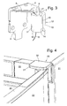
- Fig. 4 is a partial perspective view of a refrigeration device housing, in which the present invention is applied. Shown are the upper right corner of a refrigerator body 21 and a door 22, the upper end of which is formed by the already mentioned end profile 20. With respect to Fig. 1 or Fig. 3 Hinge described is hidden inside a flat housing 23 which protrudes from the front of the body 21.
- the housing 23 is constructed of two half-shells, of which the representation of Fig. 5 the top 32 is removed. It can be seen so the cable 8, coming from the recess 7 of the bearing bush 6, laterally enters a limited by a lower half-shell 25 of the housing 23 flat channel 24 and finally reaches a cavity 26 of the body 21.
- the channel 24 is bounded in the horizontal by an outer wall 27 and to the side edge 11 of the bearing arm 2 through a partition wall 28.
- the upper half-shell 32 may also be provided with engaging in the holes 5 of the bearing arm 2 locking pin so as to securely anchor the upper half-shell 32 over its entire width.
- the lower half-shell 25 may be integrally formed with a cavity 26 concealing the vertical aperture 33 of the body or attached to an edge of this panel 33 or attached thereto in any other way.
Landscapes
- Engineering & Computer Science (AREA)
- Mechanical Engineering (AREA)
- Refrigerator Housings (AREA)
- Hinges (AREA)
- Pivots And Pivotal Connections (AREA)
- Cookers (AREA)
Description
- Die vorliegende Erfindung betrifft ein Haushaltgerät wie im Oberbegriff von Anspruch 1 definiert ist. Ein solches Haushaltsgerät ist bekannt z.B. aus der
JP 2001/272162 - Eine bekannte Konstruktion eines solchen Scharniers umfasst einen Lagerarm, der an einem ersten Teil, etwa dem Korpus eines Haushaltsgerätes, befestigt werden kann, einen Achsabschnitt, der an einem seiner Längsenden fest mit einer ersten Seite des Lagerarmes verschweißt ist, einen Durchgang, der sich durch den Achsabschnitt in axialer Richtung und durch den Lagerarm erstreckt, sowie eine auf dem Achsabschnitt drehbar gehaltene Lagerhülse, die mit dem zweiten Teil, etwa der Tür des Kältegerätes, fest verbunden ist. Der Achsabschnitt ist hier durch eine geschlitzte Hülse aus Blech gebildet.
- Eine genaue Fertigung der Schweißverbindung zwischen Lagerarm und Achsabschnitt erfordert einen hohen Aufwand. Ein weiterer Nachteil ist, dass Inhomogenitäten der Schweißverbindung zu einer Ungleichverteilung von Kraftflüssen führen können, die im Laufe der Zeit zum Brechen der Schweißverbindung führen. Außerdem muss an der von der Lagerbuchse abgewandten Seite des Lagerarmes Platz vorhanden sein, damit entlang dieser Seite die Leitung durch die Bohrung des Lagerarmes hindurch in den Achsabschnitt hineingeführt werden kann.
- Die
WO 2004/048730 A (ein Stand der Technik gemäß Art. 54(3) EPÜ) offenbart ein Stromversorgungssystem für die Tür eine Kältegerätes, mit einem Korpus und einer daran angelenkten Tür. Das Scharnier weist eine Durchführung für eine elektrische Verkabelung, umfassend ein Verbindungsmittel zur Aufnahme und Befestigen eines Scharniers, eine elektrische Verkabelung, die jeweils Verbindungsmittel mit einer internen elektrischen Schaltung des Gerätes und einer externen elektrischen Schaltung aufweist, einen Kabelkanal in der Tür und eine Öffnung an der Türabschlussleiste in die ein rohrförmiger Scharnierstift hineinragt. Durch den rohrförmigen Scharnierstift ist die elektrische Verkabelung geführt. - Die
JP 2001272162 A1 - Da die Höhe von großen Haushaltsgeräten für die stationäre Aufstellung im Allgemeinen durch Rastermaße strikt vorgegeben sind, ist das bekannte hohlachsige Scharnier nicht ohne weiteres geeignet, wenn innerhalb einer existierenden Modellreihe von Geräten zusätzlich Modelle angeboten werden sollen, bei denen eine Versorgungsleitung zwischen Korpus und Tür hin- und hergeführt ist. Wenn die Konstruktion eines Gerätemodells ohne eine solche Durchführung gewissenhaft optimiert ist, kann davon ausgegangen werden, dass die Tür so groß wie möglich gemacht ist, und dass deshalb innerhalb der vorgegebenen Bauhöhe des Gerätes kein Platz mehr zur Verfügung steht, um an der von dem Achsabschnitt abgewandten Seite des Lagerarmes die Versorgungsleitung zu führen. Um mit dem existierenden Scharnier eine solche Versorgungsleitung führen zu können, müsste das Scharnier vertikal verschoben werden, was zur Folge hat, dass die Höhe der Tür angepasst werden muss. Das heißt, es muss ein anderes Türmodell angefertigt werden als bei einem Gerät, das keine Leitungsdurchführung aufweist. Dies macht die Fertigung des Gerätes mit Leitungsdurchführung kostspielig.
- Aufgabe der vorlegenden Erfindung ist daher, ein Haushaltsgerät mit einem hohlachsigen Scharnier zu schaffen, dessen Platzbedarf sich durch eine durchgeführte Versorgungsleitung nicht maßgeblich ändert.
- Die Aufgabe wird gelöst durch ein Haushaltsgerät mit einem hohlachsigen Scharnier mit den Merkmalen des Anspruches 1.
- Beim bekannten Scharnier weist der Durchgang für die Versorgungsleitung eine Öffnung in radialer Richtung in einem Abschnitt zwischen der Lagerhülse und einer von der ersten Seite abgewandten zweiten Seite des Lagerarmes auf. Dadurch kann die Versorgungsleitung aus der Durchführung in Höhe dieser Öffnung herausgeführt werden und kann infolgedessen seitlich neben dem Lagerarm weitergeführt werden. Der zusätzliche Platzbedarf, der sich herkömmlicherweise durch eine Führung der Leitung entlang der zweiten Seite des Lagerarmes ergibt, entfällt.
- Erfindungsgemäß, um ein Schweißen bei der Herstellung des Scharniers zu vermeiden, umfasst der Achsabschnitt einen Lagerzapfen, der zusammen mit dem Lagerarm aus einem Flachmaterialzuschnitt gebildet und von dem Lagerarm in der axialen Richtung abgewinkelt ist.
- Vorzugsweise ist der Lagerarm plattenförmig, wobei besagte erste und zweite Seite jeweils eine Hauptoberfläche der Platte bilden, und die Öffnung befindet sich zwischen zwei Ebenen, in denen jeweils die zwei Hauptoberflächen liegen.
- Dieser Lagerzapfen kann rund gebogen sein, um den Achsabschnitt und den Durchgang zu bilden; vorzugsweise ist allerdings der Achsabschnitt durch den Lagerzapfen und eine auf den Lagerzapfen aufgesteckte Lagerbuchse gebildet.
- Die Lagerhülse kann einfach und preiswert als Formteil aus Kunststoff realisiert sein.
- Um die Lagerhülse am Lagerzapfen zu befestigen, weist erstere vorteilhafterweise einen Längshohlraum auf, in den der Lagerzapfen eingreift. Vorzugsweise füllt der Lagerzapfen nicht den ganzen Querschnitt des Längshohlraumes aus, sondern ein Teil von ihm bildet den durch den Achsabschnitt verlaufenden Durchgang.
- Aus ästhetischen Gründen und um eine eventuell über das Scharnier verlegte Versorgungsleitung vor Beschädigung zu schützen, weist das Scharnier vorzugsweise ein Gehäuse auf, das den Lagerarm verdeckt, und ein Kanal für die Versorgungsleitung verläuft zwischen einer Außenwand des Gehäuses und der zum Durchgang des Achszapfens führenden Öffnung.
- Weitere Merkmale und Vorteile der Erfindung ergeben sich aus der nachfolgenden Beschreibung von Ausführungsbeispielen unter Bezugnahme auf die beigefügten Figuren. Es zeigen:
-
Fig. 1 eine auseinandergezogene Ansicht eines Lagerwinkels für ein erfindungsgemäßes Scharnier; -
Fig. 2 einen Schnitt durch die Lagerhülse des Lagerwinkels ausFig. 2 ; -
Fig. 3 eine Ansicht einer zweiten Ausgestaltung eines Lagerwinkels; -
Fig. 4 eine perspektivische Ansicht eines erfindungsgemäßen Scharniers mit geschlossenem Gehäuse, eingesetzt an einem Kältegerät; und -
Fig. 5 eine perspektivische Ansicht des Scharniers ausFig. 4 mit geöffnetem Gehäuse. - Das in
Fig. 1 gezeigte zum Einsatz in einen weiter unten genauer erläuterten Gerätekorpus dienende obere Scharnier setzt sich zusammen aus einem aus Flachmaterial zugeschnittenen und gebogenen Blechteil 1 mit einem plattenförmigen Lagerarm 2, von dem an einem Ende ein Befestigungsflansch 3 und an einem anderen Ende ein Lagerzapfen 4 abgewinkelt sind. Bohrungen 5 im Befestigungsflansch 3 dienen zur Befestigung des Blechteiles 1 an einen Korpus eines Haushaltsgerätes; Bohrungen 5 im Lagerarm 2 dienen zur Verrastung eines Gehäuses, wie später noch genauer erläutert wird. - Der Lagerzapfen 4 ist in sich gekrümmt, mit einer dem Befestigungsflansch 3 zugewandten konvexen Seite. Eine Lagerhülse 6 aus Kunststoff ist zum Aufstecken auf den Lagerzapfen 4 vorgesehen, wobei im aufgesteckten Zustand ein oberer Rand 10 der Lagerhülse 6 an der Unterseite 18 des Lagerarmes 2 zu liegen kommt. Die Lagerhülse 6 ist vorgesehen, um in eine hohle zylindrische Buchse 19 einzugreifen, die an einem oberen Abschlussprofil 20 aus Kunststoff einer Kältegerätetür einteilig ausgeformt ist.
- Ein nicht gezeigtes, zum Scharnier der
Fig. 1 spiegelsymmetrisches unteres Scharnier verbindet Korpus und Tür in deren unterem Bereich. - Wie der Schnitt der
Fig. 2 zeigt, ist die Lagerhülse 6 an ihrer Außenseite kreisrund und hat im Inneren eine sich über ihre gesamte Länge erstreckende Aussparung 7 mit einem Querschnitt, der in etwa zwei sich mit ihren Spitzen überlagernden Kreissektoren entspricht. Ein von der Tür ausgehendes elektrisches Kabel 8 durchläuft, wie inFig. 1 gezeigt, eine Bohrung an der unteren Spitze der Buchse 19, die Leitungsdurchführung 7 bis zu deren an der Unterseite 18 des Lagerarmes 2 anliegenden oberem Rand 10. Ab diesem oberen Rand 10 ist die Durchführung in seitlicher Richtung offen, so dass das Kabel 8 von dort aus an einer Seitenkante 11 des Lagerarmes 2 entlanggeführt werden kann. Zwei über die Oberkante 10 der Lagerhülse 6 überstehende Laschen 16 liegen an den Seitenkanten des Blechteiles 1 in einem Übergangsbereich zwischen dem Lagerzapfen 4 und dem Lagerarm 2 an, um einen Kontakt des Kabels mit eventuellen scharfen Graten des Blechteiles 1 an dieser Stelle zu verhindern. - Bei der in
Fig. 3 gezeigten Ausgestaltung des Lagerwinkels sind der Lagerarm 2 und der Befestigungsflansch 3 mit den inFig. 1 und 2 gezeigten entsprechenden Elementen identisch. Auch ein Bereich, der in Form und Lage dem Lagerzapfen 4 entspricht, ist am Lagerwinkel derFig. 3 vorhanden. Allerdings gehen von den in der Figur jeweils als gestrichelte Linien angedeuteten seitlichen Rändern 17 des Lagerzapfens 4 in seitlicher Richtung zwei Laschen 13 aus, deren Außenränder 14 gegeneinander gebogen sind, um eine Lagerhülse 12 zu schaffen, durch die sich die Aussparung 7 für die durchzuführende Leitung 8 erstreckt. Ein Spalt 15 zwischen den aufeinander zugebogenen Rändern 14 ist schmaler als der Durchmesser der durch die Aussparung 7 geführten Leitung 8, so dass diese nicht in den Spalt 15 eindringen und bei Drehung der Tür an den Wänden von deren (in der Figur nicht gezeigten) die Lagerhülse 12 aufnehmenden Buchse 19 scheuern kann. -
Fig. 4 ist eine perspektivische Teilansicht eines Kälte gerätegehäuses, in dem die vorliegende Erfindung angewendet ist. Gezeigt sind die obere rechte Ecke eines Kältegeräte-Korpus 21 und einer Tür 22, deren oberer Abschluss durch das bereits erwähnte Abschlussprofil 20 gebildet ist. Das mit Bezug aufFig. 1 oderFig. 3 beschriebene Scharnier ist im Inneren eines flachen Gehäuses 23 verborgen, das von der Vorderseite des Korpus 21 absteht. - Das Gehäuse 23 ist aufgebaut aus zwei Halbschalen, von denen der Darstellung der
Fig. 5 die obere 32 entfernt ist. Man erkennt so das Kabel 8, das, aus der Aussparung 7 der Lagerbuchse 6 kommend, seitlich in einen durch eine untere Halbschale 25 des Gehäuses 23 begrenzten flachen Kanal 24 eintritt und schließlich einen Hohlraum 26 des Korpus 21 erreicht. Der Kanal 24 ist in der Horizontalen durch eine Außenwand 27 und zu der Seitenkante 11 des Lagerarms 2 hin durch eine Trennwand 28 begrenzt. An der Außenwand 27 und an einem ins Innere des Kanals 24 gerichteten Vorsprung 29 der Trennwand 28 sind jeweils Rastausschnitte 30 gebildet, die vorgesehen sind, um Rastnasen aufzunehmen, die an einer die Außenwand 27 umgreifenden Außenwand 31 der oberen Halbschale 32 (sieheFig. 4 ) bzw. an einem nicht gezeigten, von oben zwischen die Kante 11 und den Vorsprung 29 eingreifenden Zapfen der oberen Halbschale 32 gebildet sind. Die obere Halbschale 32 kann auch mit in die Bohrungen 5 des Lagerarmes 2 eingreifenden Rastzapfen versehen sein, um so die obere Halbschale 32 auf ihrer gesamten Breite sicher zu verankern. - Die untere Halbschale 25 kann mit einer den Hohlraum 26 verdeckender vertikalen Blende 33 des Korpus einteilig ausgebildet sein oder auf eine Kante dieser Blende 33 aufgesteckt oder in anderer Weise daran befestigt sein.
Claims (8)
- Haushaltsgerät, wie Kältegerät oder dergleichen, mit einem hohlachsigen Scharnier, das ein Lagerarm (2) mit einem Achsabschnitt (4, 6; 4, 13) aufweist, der an einem seiner Längsenden fest mit einer ersten Seite (18) des Lagerarms (2) verbunden ist und einem Durchgang (7), der sich durch den Achsabschnitt (4, 6; 4, 13) in axialer Richtung erstreckt, der in einer Lagerbuchse (19) drehbar gelagert ist, der Durchgang (7) in einem zwischen der Lagerbuchse (19) und einer von der ersten Seite (18) abgewandten zweiten Seite des Lagerarms (2) liegenden Abschnitt eine Öffnung in radialer Richtung aufweist, dadurch gekennzeichnet, dass der Achsabschnitt (4, 6; 4, 13) einen Lagerzapfen (4) umfasst, der zusammen mit dem Lagerarm (2) aus einem Flachmaterialzuschnitt gebildet und von dem Lagerarm (2) in der axialen Richtung abgewinkelt ist.
- Haushaltsgerät nach Anspruch 1, dadurch gekennzeichnet, dass der Lagerarm (2) plattenförmig ausgebildet ist, wobei die erste (18) und die zweite Seite jeweils eine Hauptoberfläche der Platte bilden, und dass die Öffnung sich zwischen zwei Ebenen befindet, in denen jeweils die zwei Hauptoberflächen liegen.
- Haushaltsgerät nach Anspruch 1 oder 2, dadurch gekennzeichnet, dass das Flachmaterial rundgebogen ist, um den Achsabschnitt (4, 13) und den Durchgang (7) zu bilden.
- Haushaltsgerät nach Anspruch 1 oder 2, dadurch gekennzeichnet, dass der Achsabschnitt (4, 6) durch den Lagerzapfen (4) und eine auf den Lagerzapfen (4) aufgesteckte Lagerhülse (6) gebildet ist.
- Haushaltsgerät nach Anspruch 4, dadurch gekennzeichnet, dass die Lagerhülse (6) ein Formteil aus Kunststoff ist.
- Haushaltsgerät nach Anspruch 4 oder 5, dadurch gekennzeichnet, dass der Lagerzapfen (4) in einen Längshohlraum der Lagerbuchse (6) eingreift und zumindest in Drehrichtung des Lagerzapfens (4) form- und/oder kraftschlüssig gehalten ist.
- Haushaltsgerät nach einem der vorhergehenden Ansprüche, dadurch gekennzeichnet, dass der Lagerarm (2) von einem Gehäuse (23) verdeckt ist, und dass ein Kanal (24) sich zwischen einer Außenwand (27) des Gehäuses (23) und dem Lagerarm (2) von der Öffnung aus erstreckt.
- Haushaltsgerät nach einem der vorhergehenden Ansprüche, dadurch gekennzeichnet, dass eine elektrische Leitung (8) durch den Durchgang (7) geführt ist.
Applications Claiming Priority (2)
| Application Number | Priority Date | Filing Date | Title |
|---|---|---|---|
| DE200420007067 DE202004007067U1 (de) | 2004-05-04 | 2004-05-04 | Hohlachsiges Scharnier |
| PCT/EP2005/051963 WO2005108725A1 (de) | 2004-05-04 | 2005-04-29 | Hohlachsiges scharnier |
Publications (2)
| Publication Number | Publication Date |
|---|---|
| EP1745189A1 EP1745189A1 (de) | 2007-01-24 |
| EP1745189B1 true EP1745189B1 (de) | 2014-06-25 |
Family
ID=32603558
Family Applications (1)
| Application Number | Title | Priority Date | Filing Date |
|---|---|---|---|
| EP05742995.3A Expired - Lifetime EP1745189B1 (de) | 2004-05-04 | 2005-04-29 | Haushaltgerät mit hohlachsigem scharnier |
Country Status (6)
| Country | Link |
|---|---|
| EP (1) | EP1745189B1 (de) |
| CN (1) | CN1950582B (de) |
| DE (1) | DE202004007067U1 (de) |
| ES (1) | ES2478300T3 (de) |
| RU (1) | RU2401400C2 (de) |
| WO (1) | WO2005108725A1 (de) |
Families Citing this family (19)
| Publication number | Priority date | Publication date | Assignee | Title |
|---|---|---|---|---|
| DE102008040610A1 (de) * | 2008-07-22 | 2010-01-28 | BSH Bosch und Siemens Hausgeräte GmbH | Deckel zum Abdecken eines Lagerzapfens eines Lagerwinkels sowie damit ausgerüstetes Haushaltsgerät |
| DE102008040607A1 (de) | 2008-07-22 | 2010-02-04 | BSH Bosch und Siemens Hausgeräte GmbH | Deckel zum Abdecken eines Lagerzapfens sowie damit ausgerüstetes Haushaltsgerät |
| DE102009005140B4 (de) * | 2009-01-15 | 2020-06-25 | Jean Müller GmbH Elektrotechnische Fabrik | Kabelverteilerschrank mit Gehäuse und in diesem gelagerter Tür |
| WO2010085117A2 (ko) * | 2009-01-23 | 2010-07-29 | 엘지전자 주식회사 | 의류처리장치 |
| EP2247160B1 (de) * | 2009-05-02 | 2012-11-28 | Electrolux Home Products Corporation N.V. | Mikrowellen-Versiegelungsvorrichtung für die Öffnung einer rotierenden Welle |
| CN102201652B (zh) * | 2010-03-24 | 2015-11-25 | 海尔集团公司 | 束线盒以及电子设备 |
| DE102012202440A1 (de) * | 2012-02-17 | 2013-08-22 | BSH Bosch und Siemens Hausgeräte GmbH | Haushaltsgerät mit einer Türblatt-Lagervorrichtung |
| CN103375078B (zh) * | 2012-04-25 | 2015-12-02 | 珠海格力电器股份有限公司 | 铰链组件及具有该铰链组件的冰箱 |
| DE102013103054B4 (de) * | 2013-03-26 | 2021-01-14 | Dormakaba Deutschland Gmbh | Lagervorrichtung für eine rotatorische Lagerung einer Tür |
| ITTO20130710A1 (it) * | 2013-09-02 | 2015-03-03 | Indesit Co Spa | Apparecchio di refrigerazione con passaggio per elemento tubolare flessibile tra armadio e porta |
| DE102015206304A1 (de) * | 2015-04-09 | 2016-10-13 | BSH Hausgeräte GmbH | Haushaltsgerät mit einer elektrischen Steckverbindung |
| KR101880083B1 (ko) * | 2015-07-29 | 2018-07-20 | 삼성전자주식회사 | 세탁기 |
| CN107386843B (zh) * | 2017-09-05 | 2018-11-23 | 长虹美菱股份有限公司 | 一种门铰链盒组件 |
| FR3090723B1 (fr) * | 2018-12-21 | 2022-08-12 | Safran Electrical & Power | Charnière de porte pour meuble électrique |
| CN109780191A (zh) * | 2019-03-18 | 2019-05-21 | 北京电影学院 | 一种齿轮副驱动机构及含有其的摄影机械臂 |
| CN111255318A (zh) * | 2020-01-17 | 2020-06-09 | 刘知迪 | 一种内置电线的合页组合 |
| DE102020213908A1 (de) * | 2020-11-05 | 2022-05-05 | BSH Hausgeräte GmbH | Haushaltsgerät mit einem symmetrischen Lagerwinkel eines Scharniers für eine Tür, sowie Verfahren |
| CN114635614B (zh) * | 2022-03-02 | 2023-08-08 | 澳柯玛股份有限公司 | 一种铰链、冰箱和铰链工作方法 |
| JP7796387B2 (ja) * | 2022-06-15 | 2026-01-09 | 株式会社ベスト | 開き扉用ヒンジ |
Citations (1)
| Publication number | Priority date | Publication date | Assignee | Title |
|---|---|---|---|---|
| JP2001272162A (ja) * | 2000-03-28 | 2001-10-05 | Toshiba Corp | 冷蔵庫扉の配線構造 |
Family Cites Families (7)
| Publication number | Priority date | Publication date | Assignee | Title |
|---|---|---|---|---|
| US2522989A (en) * | 1947-03-25 | 1950-09-19 | Gen Electric | Electrical connection for hinged structures |
| SU868899A1 (ru) * | 1980-01-08 | 1981-09-30 | За витель -;- u:.l л. bKS.ihl:) i | Электрическое шарнирное соединение |
| US4543800A (en) * | 1984-02-16 | 1985-10-01 | White Consolidated Industries, Inc. | Refrigerator door hinge |
| CA2273475C (en) * | 1999-05-27 | 2004-07-13 | Nedo Banicevic | Refrigerator door epaulet |
| DE29918401U1 (de) * | 1999-10-19 | 2000-01-13 | Dettlaff, Ulrike, Dipl.-Ing. (TU), 70378 Stuttgart | Türscharnier für Gargeräte mit Kabeldurchführung |
| CN1541298A (zh) * | 2001-06-11 | 2004-10-27 | �����.�Ҹ�ɳ�����������ι�˾ | 装配有一种集成的无级制动和保持机构的门铰链 |
| BR0205050A (pt) | 2002-11-25 | 2004-06-29 | Multibras Eletrodomesticos Sa | Sistema de alimentação elétrica para porta de refrigeradores e freezers |
-
2004
- 2004-05-04 DE DE200420007067 patent/DE202004007067U1/de not_active Expired - Lifetime
-
2005
- 2005-04-29 WO PCT/EP2005/051963 patent/WO2005108725A1/de not_active Ceased
- 2005-04-29 EP EP05742995.3A patent/EP1745189B1/de not_active Expired - Lifetime
- 2005-04-29 RU RU2006137812/21A patent/RU2401400C2/ru active
- 2005-04-29 ES ES05742995.3T patent/ES2478300T3/es not_active Expired - Lifetime
- 2005-04-29 CN CN200580014173.8A patent/CN1950582B/zh not_active Expired - Fee Related
Patent Citations (1)
| Publication number | Priority date | Publication date | Assignee | Title |
|---|---|---|---|---|
| JP2001272162A (ja) * | 2000-03-28 | 2001-10-05 | Toshiba Corp | 冷蔵庫扉の配線構造 |
Also Published As
| Publication number | Publication date |
|---|---|
| DE202004007067U1 (de) | 2004-06-24 |
| RU2006137812A (ru) | 2008-06-10 |
| EP1745189A1 (de) | 2007-01-24 |
| WO2005108725A1 (de) | 2005-11-17 |
| CN1950582A (zh) | 2007-04-18 |
| CN1950582B (zh) | 2015-04-15 |
| RU2401400C2 (ru) | 2010-10-10 |
| ES2478300T3 (es) | 2014-07-21 |
Similar Documents
| Publication | Publication Date | Title |
|---|---|---|
| EP1745189A1 (de) | Hohlachsiges scharnier | |
| EP2559120B1 (de) | Gehäuseteil für einen schaltschrank | |
| EP1745188B1 (de) | Lagerwinkel mit Leitungsdurchführung | |
| WO2009132972A1 (de) | Haushaltsgerät | |
| EP2281095B1 (de) | Haushaltsgerät | |
| EP2307830B1 (de) | Haushaltgerät ausgerüstet mit einem Deckel zum Abdecken eines Lagerzapfens | |
| EP1926953B1 (de) | Tür für ein haushaltsgerät | |
| WO2009132943A1 (de) | Scharnierelement und gehäuse für ein haushaltsgerät | |
| EP2283195B1 (de) | Scharnierelement und gehäuse für ein haushaltsgerät | |
| DE3405343A1 (de) | Viergelenk-moebelscharnier mit vergroesstertem oeffnungswinkel | |
| DE19738931C1 (de) | Scharnier für Behälterabdeckungen | |
| EP3566271B1 (de) | Schaltschranktür für ein schaltschrankgehäuse | |
| DE102005047080B3 (de) | Scharnier für eine Gerätetüre | |
| DE102004062238A1 (de) | Einbauhaushaltsgerät | |
| EP1617025B1 (de) | Scharnier für stumpf einschlagende Türen | |
| DE19746118C2 (de) | Gehäuse | |
| EP2484998A2 (de) | Haushaltsgerät | |
| DE3315999C2 (de) | Auszieheinrichtung für einen mit einem Möbelkorpus versehenen Schrank | |
| DE2630121A1 (de) | Scharnier fuer kraftwagentueren | |
| DE69718728T2 (de) | Türscharnier, insbesondere für Kraftfahrzeug | |
| DE102008042944B4 (de) | Geschirrspülmaschine mit einem Frontelement | |
| CH385950A (de) | Unterputz-Abzweigeinrichtung für elektrische Leitungen | |
| EP4560106A1 (de) | Befestigungsvorrichtung für einen aufsatzrollladenkasten, aufsatzrollladenkasten sowie fenster / tür mit einem aufsatzrollladenkasten | |
| WO2022122492A1 (de) | Montagevorrichtung | |
| DE20313510U1 (de) | Beschlag mit doppeltem Kniegelenk |
Legal Events
| Date | Code | Title | Description |
|---|---|---|---|
| PUAI | Public reference made under article 153(3) epc to a published international application that has entered the european phase |
Free format text: ORIGINAL CODE: 0009012 |
|
| 17P | Request for examination filed |
Effective date: 20061204 |
|
| AK | Designated contracting states |
Kind code of ref document: A1 Designated state(s): AT BE BG CH CY CZ DE DK EE ES FI FR GB GR HU IE IS IT LI LT LU MC NL PL PT RO SE SI SK TR |
|
| DAX | Request for extension of the european patent (deleted) | ||
| 17Q | First examination report despatched |
Effective date: 20080807 |
|
| GRAP | Despatch of communication of intention to grant a patent |
Free format text: ORIGINAL CODE: EPIDOSNIGR1 |
|
| INTG | Intention to grant announced |
Effective date: 20140211 |
|
| GRAS | Grant fee paid |
Free format text: ORIGINAL CODE: EPIDOSNIGR3 |
|
| GRAA | (expected) grant |
Free format text: ORIGINAL CODE: 0009210 |
|
| AK | Designated contracting states |
Kind code of ref document: B1 Designated state(s): AT BE BG CH CY CZ DE DK EE ES FI FR GB GR HU IE IS IT LI LT LU MC NL PL PT RO SE SI SK TR |
|
| REG | Reference to a national code |
Ref country code: GB Ref legal event code: FG4D Free format text: NOT ENGLISH |
|
| REG | Reference to a national code |
Ref country code: CH Ref legal event code: EP |
|
| REG | Reference to a national code |
Ref country code: AT Ref legal event code: REF Ref document number: 674833 Country of ref document: AT Kind code of ref document: T Effective date: 20140715 |
|
| REG | Reference to a national code |
Ref country code: IE Ref legal event code: FG4D Free format text: LANGUAGE OF EP DOCUMENT: GERMAN |
|
| REG | Reference to a national code |
Ref country code: ES Ref legal event code: FG2A Ref document number: 2478300 Country of ref document: ES Kind code of ref document: T3 Effective date: 20140721 |
|
| REG | Reference to a national code |
Ref country code: DE Ref legal event code: R096 Ref document number: 502005014411 Country of ref document: DE Effective date: 20140731 |
|
| PG25 | Lapsed in a contracting state [announced via postgrant information from national office to epo] |
Ref country code: FI Free format text: LAPSE BECAUSE OF FAILURE TO SUBMIT A TRANSLATION OF THE DESCRIPTION OR TO PAY THE FEE WITHIN THE PRESCRIBED TIME-LIMIT Effective date: 20140625 Ref country code: GR Free format text: LAPSE BECAUSE OF FAILURE TO SUBMIT A TRANSLATION OF THE DESCRIPTION OR TO PAY THE FEE WITHIN THE PRESCRIBED TIME-LIMIT Effective date: 20140926 Ref country code: LT Free format text: LAPSE BECAUSE OF FAILURE TO SUBMIT A TRANSLATION OF THE DESCRIPTION OR TO PAY THE FEE WITHIN THE PRESCRIBED TIME-LIMIT Effective date: 20140625 Ref country code: CY Free format text: LAPSE BECAUSE OF FAILURE TO SUBMIT A TRANSLATION OF THE DESCRIPTION OR TO PAY THE FEE WITHIN THE PRESCRIBED TIME-LIMIT Effective date: 20140625 |
|
| REG | Reference to a national code |
Ref country code: NL Ref legal event code: VDEP Effective date: 20140625 |
|
| REG | Reference to a national code |
Ref country code: LT Ref legal event code: MG4D |
|
| PG25 | Lapsed in a contracting state [announced via postgrant information from national office to epo] |
Ref country code: SE Free format text: LAPSE BECAUSE OF FAILURE TO SUBMIT A TRANSLATION OF THE DESCRIPTION OR TO PAY THE FEE WITHIN THE PRESCRIBED TIME-LIMIT Effective date: 20140625 |
|
| PG25 | Lapsed in a contracting state [announced via postgrant information from national office to epo] |
Ref country code: EE Free format text: LAPSE BECAUSE OF FAILURE TO SUBMIT A TRANSLATION OF THE DESCRIPTION OR TO PAY THE FEE WITHIN THE PRESCRIBED TIME-LIMIT Effective date: 20140625 Ref country code: SK Free format text: LAPSE BECAUSE OF FAILURE TO SUBMIT A TRANSLATION OF THE DESCRIPTION OR TO PAY THE FEE WITHIN THE PRESCRIBED TIME-LIMIT Effective date: 20140625 Ref country code: RO Free format text: LAPSE BECAUSE OF FAILURE TO SUBMIT A TRANSLATION OF THE DESCRIPTION OR TO PAY THE FEE WITHIN THE PRESCRIBED TIME-LIMIT Effective date: 20140625 Ref country code: CZ Free format text: LAPSE BECAUSE OF FAILURE TO SUBMIT A TRANSLATION OF THE DESCRIPTION OR TO PAY THE FEE WITHIN THE PRESCRIBED TIME-LIMIT Effective date: 20140625 Ref country code: PT Free format text: LAPSE BECAUSE OF FAILURE TO SUBMIT A TRANSLATION OF THE DESCRIPTION OR TO PAY THE FEE WITHIN THE PRESCRIBED TIME-LIMIT Effective date: 20141027 |
|
| PG25 | Lapsed in a contracting state [announced via postgrant information from national office to epo] |
Ref country code: IS Free format text: LAPSE BECAUSE OF FAILURE TO SUBMIT A TRANSLATION OF THE DESCRIPTION OR TO PAY THE FEE WITHIN THE PRESCRIBED TIME-LIMIT Effective date: 20141025 Ref country code: PL Free format text: LAPSE BECAUSE OF FAILURE TO SUBMIT A TRANSLATION OF THE DESCRIPTION OR TO PAY THE FEE WITHIN THE PRESCRIBED TIME-LIMIT Effective date: 20140625 Ref country code: NL Free format text: LAPSE BECAUSE OF FAILURE TO SUBMIT A TRANSLATION OF THE DESCRIPTION OR TO PAY THE FEE WITHIN THE PRESCRIBED TIME-LIMIT Effective date: 20140625 |
|
| REG | Reference to a national code |
Ref country code: CH Ref legal event code: PFA Owner name: BSH HAUSGERAETE GMBH, DE Free format text: FORMER OWNER: BSH BOSCH UND SIEMENS HAUSGERAETE GMBH, DE |
|
| RAP2 | Party data changed (patent owner data changed or rights of a patent transferred) |
Owner name: BSH HAUSGERAETE GMBH |
|
| REG | Reference to a national code |
Ref country code: DE Ref legal event code: R097 Ref document number: 502005014411 Country of ref document: DE |
|
| REG | Reference to a national code |
Ref country code: FR Ref legal event code: PLFP Year of fee payment: 11 |
|
| PG25 | Lapsed in a contracting state [announced via postgrant information from national office to epo] |
Ref country code: DK Free format text: LAPSE BECAUSE OF FAILURE TO SUBMIT A TRANSLATION OF THE DESCRIPTION OR TO PAY THE FEE WITHIN THE PRESCRIBED TIME-LIMIT Effective date: 20140625 |
|
| PLBE | No opposition filed within time limit |
Free format text: ORIGINAL CODE: 0009261 |
|
| STAA | Information on the status of an ep patent application or granted ep patent |
Free format text: STATUS: NO OPPOSITION FILED WITHIN TIME LIMIT |
|
| REG | Reference to a national code |
Ref country code: DE Ref legal event code: R081 Ref document number: 502005014411 Country of ref document: DE Owner name: BSH HAUSGERAETE GMBH, DE Free format text: FORMER OWNER: BSH BOSCH UND SIEMENS HAUSGERAETE GMBH, 81739 MUENCHEN, DE Effective date: 20150407 Ref country code: DE Ref legal event code: R081 Ref document number: 502005014411 Country of ref document: DE Owner name: BSH HAUSGERAETE GMBH, DE Free format text: FORMER OWNER: BSH BOSCH UND SIEMENS HAUSGERAETE GMBH, 81739 MUENCHEN, DE Effective date: 20140626 |
|
| REG | Reference to a national code |
Ref country code: ES Ref legal event code: PC2A Owner name: BSH HAUSGERATE GMBH Effective date: 20150527 |
|
| 26N | No opposition filed |
Effective date: 20150326 |
|
| REG | Reference to a national code |
Ref country code: FR Ref legal event code: CD Owner name: BSH HAUSGERATE GMBH Effective date: 20151022 |
|
| PG25 | Lapsed in a contracting state [announced via postgrant information from national office to epo] |
Ref country code: MC Free format text: LAPSE BECAUSE OF FAILURE TO SUBMIT A TRANSLATION OF THE DESCRIPTION OR TO PAY THE FEE WITHIN THE PRESCRIBED TIME-LIMIT Effective date: 20140625 Ref country code: SI Free format text: LAPSE BECAUSE OF FAILURE TO SUBMIT A TRANSLATION OF THE DESCRIPTION OR TO PAY THE FEE WITHIN THE PRESCRIBED TIME-LIMIT Effective date: 20140625 Ref country code: LU Free format text: LAPSE BECAUSE OF FAILURE TO SUBMIT A TRANSLATION OF THE DESCRIPTION OR TO PAY THE FEE WITHIN THE PRESCRIBED TIME-LIMIT Effective date: 20150429 |
|
| REG | Reference to a national code |
Ref country code: CH Ref legal event code: PL |
|
| REG | Reference to a national code |
Ref country code: IE Ref legal event code: MM4A |
|
| PG25 | Lapsed in a contracting state [announced via postgrant information from national office to epo] |
Ref country code: CH Free format text: LAPSE BECAUSE OF NON-PAYMENT OF DUE FEES Effective date: 20150430 Ref country code: LI Free format text: LAPSE BECAUSE OF NON-PAYMENT OF DUE FEES Effective date: 20150430 |
|
| REG | Reference to a national code |
Ref country code: FR Ref legal event code: PLFP Year of fee payment: 12 |
|
| PG25 | Lapsed in a contracting state [announced via postgrant information from national office to epo] |
Ref country code: IE Free format text: LAPSE BECAUSE OF NON-PAYMENT OF DUE FEES Effective date: 20150429 |
|
| REG | Reference to a national code |
Ref country code: AT Ref legal event code: MM01 Ref document number: 674833 Country of ref document: AT Kind code of ref document: T Effective date: 20150429 |
|
| PGFP | Annual fee paid to national office [announced via postgrant information from national office to epo] |
Ref country code: ES Payment date: 20160422 Year of fee payment: 12 |
|
| PG25 | Lapsed in a contracting state [announced via postgrant information from national office to epo] |
Ref country code: AT Free format text: LAPSE BECAUSE OF NON-PAYMENT OF DUE FEES Effective date: 20150429 |
|
| PGFP | Annual fee paid to national office [announced via postgrant information from national office to epo] |
Ref country code: FR Payment date: 20160422 Year of fee payment: 12 |
|
| PG25 | Lapsed in a contracting state [announced via postgrant information from national office to epo] |
Ref country code: HU Free format text: LAPSE BECAUSE OF FAILURE TO SUBMIT A TRANSLATION OF THE DESCRIPTION OR TO PAY THE FEE WITHIN THE PRESCRIBED TIME-LIMIT; INVALID AB INITIO Effective date: 20050429 Ref country code: BG Free format text: LAPSE BECAUSE OF FAILURE TO SUBMIT A TRANSLATION OF THE DESCRIPTION OR TO PAY THE FEE WITHIN THE PRESCRIBED TIME-LIMIT Effective date: 20140625 |
|
| PG25 | Lapsed in a contracting state [announced via postgrant information from national office to epo] |
Ref country code: BE Free format text: LAPSE BECAUSE OF NON-PAYMENT OF DUE FEES Effective date: 20150430 |
|
| PGFP | Annual fee paid to national office [announced via postgrant information from national office to epo] |
Ref country code: GB Payment date: 20170425 Year of fee payment: 13 |
|
| REG | Reference to a national code |
Ref country code: FR Ref legal event code: ST Effective date: 20171229 |
|
| PG25 | Lapsed in a contracting state [announced via postgrant information from national office to epo] |
Ref country code: FR Free format text: LAPSE BECAUSE OF NON-PAYMENT OF DUE FEES Effective date: 20170502 |
|
| REG | Reference to a national code |
Ref country code: ES Ref legal event code: FD2A Effective date: 20180629 |
|
| PG25 | Lapsed in a contracting state [announced via postgrant information from national office to epo] |
Ref country code: ES Free format text: LAPSE BECAUSE OF NON-PAYMENT OF DUE FEES Effective date: 20170430 |
|
| GBPC | Gb: european patent ceased through non-payment of renewal fee |
Effective date: 20180429 |
|
| PG25 | Lapsed in a contracting state [announced via postgrant information from national office to epo] |
Ref country code: GB Free format text: LAPSE BECAUSE OF NON-PAYMENT OF DUE FEES Effective date: 20180429 |
|
| PGFP | Annual fee paid to national office [announced via postgrant information from national office to epo] |
Ref country code: IT Payment date: 20220429 Year of fee payment: 18 Ref country code: DE Payment date: 20220430 Year of fee payment: 18 |
|
| PGFP | Annual fee paid to national office [announced via postgrant information from national office to epo] |
Ref country code: TR Payment date: 20220421 Year of fee payment: 18 |
|
| REG | Reference to a national code |
Ref country code: DE Ref legal event code: R084 Ref document number: 502005014411 Country of ref document: DE |
|
| REG | Reference to a national code |
Ref country code: DE Ref legal event code: R119 Ref document number: 502005014411 Country of ref document: DE |
|
| PG25 | Lapsed in a contracting state [announced via postgrant information from national office to epo] |
Ref country code: DE Free format text: LAPSE BECAUSE OF NON-PAYMENT OF DUE FEES Effective date: 20231103 |
|
| PG25 | Lapsed in a contracting state [announced via postgrant information from national office to epo] |
Ref country code: IT Free format text: LAPSE BECAUSE OF NON-PAYMENT OF DUE FEES Effective date: 20230429 |