EP1741491B1 - Rotierendes Messer für eine Zerkleinerungsvorrichtung - Google Patents
Rotierendes Messer für eine Zerkleinerungsvorrichtung Download PDFInfo
- Publication number
- EP1741491B1 EP1741491B1 EP06252531A EP06252531A EP1741491B1 EP 1741491 B1 EP1741491 B1 EP 1741491B1 EP 06252531 A EP06252531 A EP 06252531A EP 06252531 A EP06252531 A EP 06252531A EP 1741491 B1 EP1741491 B1 EP 1741491B1
- Authority
- EP
- European Patent Office
- Prior art keywords
- channels
- rotary knife
- blade
- blades
- knife
- Prior art date
- Legal status (The legal status is an assumption and is not a legal conclusion. Google has not performed a legal analysis and makes no representation as to the accuracy of the status listed.)
- Not-in-force
Links
- 235000013372 meat Nutrition 0.000 claims description 40
- 235000013305 food Nutrition 0.000 claims description 27
- 230000007423 decrease Effects 0.000 claims description 7
- 229910000831 Steel Inorganic materials 0.000 description 3
- 239000010959 steel Substances 0.000 description 3
- 238000000034 method Methods 0.000 description 2
- 230000001154 acute effect Effects 0.000 description 1
- 230000004888 barrier function Effects 0.000 description 1
- 239000006227 byproduct Substances 0.000 description 1
- 235000013351 cheese Nutrition 0.000 description 1
- 238000005056 compaction Methods 0.000 description 1
- 239000003814 drug Substances 0.000 description 1
- 235000015220 hamburgers Nutrition 0.000 description 1
- 238000012986 modification Methods 0.000 description 1
- 230000004048 modification Effects 0.000 description 1
- 235000020991 processed meat Nutrition 0.000 description 1
- 230000000717 retained effect Effects 0.000 description 1
- 235000013580 sausages Nutrition 0.000 description 1
- 238000010008 shearing Methods 0.000 description 1
- 235000013311 vegetables Nutrition 0.000 description 1
- 239000002699 waste material Substances 0.000 description 1
Images

Classifications
-
- B—PERFORMING OPERATIONS; TRANSPORTING
- B02—CRUSHING, PULVERISING, OR DISINTEGRATING; PREPARATORY TREATMENT OF GRAIN FOR MILLING
- B02C—CRUSHING, PULVERISING, OR DISINTEGRATING IN GENERAL; MILLING GRAIN
- B02C18/00—Disintegrating by knives or other cutting or tearing members which chop material into fragments
- B02C18/30—Mincing machines with perforated discs and feeding worms
- B02C18/36—Knives or perforated discs
- B02C18/362—Knives
Definitions
- the present invention relates to a rotary knife for use in a cutting apparatus such as an industrial food processor, and a cutting apparatus comprising such a knife.
- industrial food processors such as meat grinders, are used to process meat into the consistency of sausage meat or burger meat, for example.
- an industrial food processor generally comprises a steel rotary knife 10 mounted coaxially between a first perforated disc 12 and a second perforated disc 14 that are also made of steel.
- the discs 12 and 14 are fixed within a tubular housing (not shown).
- the knife 10 is rotatable about an axis of the food processor. A diameter of the knife 10 is smaller than a diameter of the discs 12 and 14.
- the knife 10 comprises a central aperture 16, a hub 18, and eight arms 20 extending outwards from the hub 18.
- the central aperture 16 is adapted to receive a driveshaft (not shown). In use, the driveshaft rotates about the axis of rotation in order to rotate the knife 10.
- the discs 12 and 14 comprise circular central apertures 22 and 24 respectively, entry surfaces 26 and 30 respectively, and exit surfaces 28 and 32 respectively. In use, the driveshaft may rotate freely relative to the discs 12 and 14 within the circular central apertures 22 and 24.
- the discs 12 and 14 further comprise a plurality of holes 34 and 36 respectively.
- the holes 34 and 36 extend through the discs 12 and 14 in a direction parallel to the axis of rotation of the knife 10.
- the holes 34 in the first disc 12 are larger than the holes 36 in the second disc 14.
- Each arm 20 of the knife 10 has respective first and second ends 40 and 42 respectively, the first end 40 being free and the second end 42 being connected to the hub 18 by means of a substantially annular portion 44 which surrounds the hub 18.
- a dimension of the annular portion 44 in the axial direction is less than that of the hub 18 such that the hub 18 protrudes axially from the annular portion 44.
- Each arm 20 comprises a respective blade 46 that is substantially V-shaped in profile when viewed from the first end 40 of the arm 20.
- An axial dimension of each blade 46 is greater than the axial dimension of the annular portion 44 such that the blades 46 also protrude axially from the annular portion 44.
- Each blade 46 comprises two planar surfaces 48 and 50 forming the V-shaped profile and two disc-engaging surfaces 52 and 54 that are perpendicular to the axis of rotation.
- the disc-engaging surfaces 52 and 54 and the planar surfaces 48 and 50 are arranged to have a substantially W-shaped profile when viewed from the first end 40 of the arm 20.
- Serrations 56 are provided in the blade 46 along an edge 60 joining the planar surface 48 with the disc-engaging surface 52.
- serrations 58 are provided in the blade 46 along an edge 62 joining the planar surface 50 with the disc-engaging surface 54.
- meat for example, is fed through the food processor in the direction shown by arrow X.
- the meat is fed through the food processor using, for example, a feed auger (not shown) which also rotates about the axis of rotation.
- the driveshaft rotates the knife 10 in the direction shown by arrow Y such that the V-shaped blades 46 are on the forward edge of the arms 20 with the V-shaped profile pointing rearwardly with respect to the direction of rotation.
- the disc-engaging surface 54 rotates flush with the exit surface 28 of the first disc 12, and the disc-engaging surface 52 rotates flush with the entry surface 30 of the second disc 14.
- the disc-engaging surface 54 rotates flush with the exit surface 28 of the first disc 12
- the disc-engaging surface 52 rotates flush with the entry surface 30 of the second disc 14.
- the blades 46 of the knife 10 cut the meat as the knife 10 rotates. More specifically, the meat is cut by a scissor action between edges of the serrations 58 and edges of the holes 34.
- the meat continues to be forced through the food processor by the feed auger in direction X.
- some meat escapes around the first ends 40 of the knife arms 20 due to the reduced diameter of the knife 10 compared to that of the discs 12 and 14. This reduces the efficiency of the food processor.
- the meat reaches the second disc 14 within range of an arm 20.
- the blades 46 of the knife 10 cut the meat for a second time as the knife 10 rotates. More specifically, the meat is cut by a scissor action between edges of the serrations 56 and edges of the holes 36.
- the processed meat is collected when it emerges from the holes 36 in the exit surface 32 of the second disc 14.
- the amount of meat which can be processed by an industrial food processor in a given time is of key importance.
- the present invention seeks to provide an improved rotary knife which enables more efficient operation of a cutting apparatus such as an industrial food processor.
- RU 2,184,613 describes a cutting unit having a grid and a knife for use in food-processing and other branches of industry.
- the grid is made in the form of a disk with through openings arranged in concentric circles and blind openings. Cutting edges of the knife blades are formed by intersected openings arranged in concentric circles.
- One pair of blades has openings arranged at an acute angle to knife working surfaces and another pair of blades has opening arranged at right angles to said surface.
- a rotary knife for use in a cutting apparatus, comprising a central hub adapted to be mounted with respect to a rotational driveshaft to define an axis of rotation; and a plurality of blades extending outwards from the hub; each blade having respective channels extending across a surface of the blade in a direction substantially parallel to the axis of rotation. A dimension of the channels varies along the length of the channels.
- a depth of the channels varies along the length of the channels. More advantageously, the depth of the channels decreases towards the centre of the channels.
- a width of the channels varies along the length of the channels. More advantageously, the width of the channels decreases towards the centre of the channels.
- a depth of the channels is approximately half of a circumferential dimension of the blades.
- a cutting apparatus having a rotary knife according to the first aspect.
- the cutting apparatus is an industrial food processor. More advantageously, the cutting apparatus is a meat grinder.
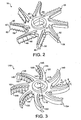
- FIG 3 is a perspective view of a rotary knife 110 according to an embodiment of the present invention.
- the knife 110 is adapted for use in a cutting apparatus such as an industrial food processor.
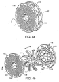
- a cutting apparatus is an industrial food processor comprising the knife 110 mounted coaxially between two perforated discs 112 and 114 as shown in Figures 4a and 4b .
- the discs 112 and 114 are fixed within a tubular housing (not shown).
- the knife 110 is rotatable about an axis of the food processor in a direction shown by arrow Z by means of a driveshaft (not shown). Food is fed through the food processor in the direction shown by arrow W.
- a diameter of the knife 110 is smaller than a diameter of the discs 112 and 114.
- an industrial food processor may contain a further knife 110 and disc such that the configuration of components within the tubular housing comprises two knives 110 interposed between three discs in a disc-knife-disc-knife-disc arrangement.
- the discs 112 and 114 are similar to those already described with reference to the prior art so they will only be described briefly here.
- the discs 112 and 114 comprise circular central apertures 122 and 124 respectively, entry surfaces 126 and 130 respectively, and exit surfaces 128 and 132 respectively.
- the driveshaft may rotate freely relative to the discs 112 and 114 within the circular central apertures 122 and 124.
- the discs 112 and 114 further comprise a plurality of circular holes 134 and 136 respectively.
- the holes 134 and 136 extend through the discs 112 and 114 in a direction parallel to the axis of rotation of the knife 110.
- the holes 134 in the first disc 112 are larger than the holes 136 in the second disc 114.
- the knife 110 comprises a central aperture 116, a hub 118, and eight arms 120 extending outwards from the hub 118.
- the central aperture 116 is adapted to receive the driveshaft in order to rotate the knife 110 in use.
- the knife 110 need not have eight arms; in alternative embodiments, knives are provided with four arms, six arms or ten arms. Further alternative arrangements are also envisaged.
- the knife 110 is integrally formed from a single piece of steel, for example.
- the arms 120 need not be integrally formed with the hub 118.
- Each arm 120 of the knife 110 has respective first and second ends 140 and 142, the first end 140 being free and the second end 142 being connected to the hub 118 by means of a substantially annular portion 144 which surrounds the hub 118.
- An axial dimension of the annular portion 144 is less than that of the hub 118 such that the hub 118 protrudes axially from the annular portion 144.
- Each arm 120 comprises a respective supporting portion 145 and a respective blade 146.
- the supporting portion 145 merges with and is integrally formed with the annular portion 144.
- the blade 146 is positioned forward of the supporting portion 145 with respect to the rotational direction Z.
- the blade is substantially V-shaped in profile when viewed from the first end 140 of the arm 120.
- the V-shaped profile is arranged such that in use the V-shaped profile points rearwardly with respect to the rotational direction Z.
- An axial dimension of the supporting portion 145 is the same as that of the annular portion 144, whereas an axial dimension of each blade 146 is greater than the axial dimension of the annular portion 144.
- the blades 146 protrude axially from the annular portion 144.
- only the blades 146, and not the supporting portions 145 make contact with the discs 112 and 114.
- Each arm 120 is arcuate between the first and second ends 140 and 142 of the arm 120.
- the blades 156 and the supporting portions 145 are also arcuate between the first and second ends 140 and 142 of the respective arms 120.
- the use of a curved blade is advantageous because the cutting length of the blade is increased (i.e. a curved line between two points is longer than a straight line between the same two points).
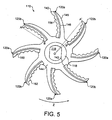
- each blade is concave.
- Line AB is a straight line connecting the first end 140 of the blade 146 to the second end 142 of the same blade 146.
- the concave blade 146 bows rearwardly from line AB relative to the rotational direction Z.
- each blade 146 is arranged such that the first end 140 is forward of the second end 142 with respect to the rotational direction Z. Again, this is clearly seen in Figure 5 .
- Line OA' is a straight line connecting the rotational axis (indicated as a point O in this view) to the first end 140 of the blade 146, and line OB' is a straight line connecting the rotational axis to the second end 142 of the same blade 146.
- the line OA' is forward of the line OB' relative to the rotational direction Z.
- each blade 146 comprises two surfaces 148 and 150 forming the V-shaped profile and two disc-engaging surfaces 152 and 154 that are perpendicular to the axis of rotation.
- the disc-engaging surfaces 152 and 154 and the V-surfaces 148 and 150 are arranged to have a substantially W-shaped profile when viewed from the first end 140 of the arm 120.
- the disc-engaging surfaces 152 and 154 are the only parts of each blade 146 in contact with the discs 112 and 114.
- Each blade 146 further comprises a plurality of channels 156 extending across the V-surfaces 148 and 150 of the blade 146 from the disc-engaging surface 152 to the disc-engaging surface 154.
- the channels 156 run in a substantially axial direction.
- Each channel 156 has an arcuate cross-section.
- Arcuate cross-sections 158 at the disc-engaging surfaces 152 and 154 are approximately semi-circular.
- the disc-engaging surfaces 152 and 154 comprise scalloped edges 153 and 155 respectively.
- a depth D of the channels 156 at the disc-engaging surfaces 152 and 154 is approximately half of a corresponding circumferential dimension E of the blades 146 at the disc-engaging surfaces 152 and 154.
- the depth of the channels 156 varies along the length of the channels 156 such that the depth of the channels 156 decreases towards the centre of the channels 156.
- a width F of the channels 156 varies along the length of the channels 156 such that the width of the channels 156 decreases towards the centre of the channels 156.
- ridges 157 between the channels 156 have a width G that increases towards the centre of the ridges 157.
- each blade 146 The channels 156 on each blade 146 are radially offset from the channels 156 on adjacent blades 146. Again, this is seen more clearly in Figure 4 .
- Four arms 120a comprise five channels 156, and four arms 120b comprise six channels 156.
- Each arm 120a is adjacent to two respective arms 120b.
- Channel centres 160 of arms 120a are located at the same radial positions as ridges 162 between the channels 156 of arms 120b.
- the disc-engaging surface 154 rotates flush with the exit surface 128 of the first disc 112, and the disc-engaging surface 152 rotates flush with the entry surface 130 of the second disc 114.
- the areas of the disc-engaging surfaces 152 and 154 are reduced compared to prior art knives due to the channels 156.
- the depth D of the channels 156 is relatively large so that there are large areas cut out of the disc-engaging surfaces 152 and 154 to form the channels 156.
- This feature in combination with the reduced circumferential dimension of the supporting portions 145 compared with that of the blades 146, ensures that there is a smaller contact area between the knife 110 and the discs compared to the prior art, so that friction is reduced and the efficiency of the industrial food processor is increased.
- the blades 146 of the knife 110 cut the meat as the knife 110 rotates. More specifically, the meat is cut by a scissor action between the scalloped edge 155 of the blade 146 and edges of the holes 134. Due again to the relatively large depth D of the channels 156, the cutting length of the blade 146 (i.e. the total length of scalloped edge 155) is increased compared to prior art knives. The cutting length of the blade 146 is further increased by the arcuate shape of the blade 146 compared to the straight blades 46 of the prior art rotary knife 10. Thus, the efficiency of the food processor is further increased due to more meat being cut by the increased cutting length of the blade 146.
- the channels 156 assist in moving the meat efficiently from the exit surface 128 of the first disc 112 to the entry surface 130 of the second disc 114. Meat that has been cut as it emerged from the first disc 112 is channelled along the channels 156 towards the second disc 114.
- meat takes an efficient (i.e. short) route between the discs 112 and 114.
- meat moves more efficiently through the food processor in direction W so that less power is required to process a given amount of meat in a given time.
- the efficiency of the food processor is further increased by the concave curved blades 146 which help to retain meat, for example, in the area swept by the blades 146 so that less meat escapes around the first ends 140 of the arms 120. This is further helped by the concave arc of each blade 146 being arranged such that the first end 140 is forward of the second end 142 with respect to the rotational direction Z.
- the meat movement since the meat is retained by the curved arms 120, the meat movement has a smaller radial component than in the prior art, so there is less shearing and a cleaner cut is achieved using the present knife 120.
- the ridges 157 between the channels 156 also prevent meat sliding radially with respect to the blades 146 by acting as barriers between the channels 156.
- the blades 146 of the knife 110 cut the meat for a second time as the knife 110 rotates. More specifically, the meat is cut by a scissor action between the scalloped edge 153 of the blade 146 and edges of the holes 136. Again, the scalloped edge 153 has a longer cutting edge which contributes to increased food processor efficiency.
Landscapes
- Engineering & Computer Science (AREA)
- Food Science & Technology (AREA)
- Crushing And Pulverization Processes (AREA)
- Shearing Machines (AREA)
- Finish Polishing, Edge Sharpening, And Grinding By Specific Grinding Devices (AREA)
- Threshing Machine Elements (AREA)
- Processing Of Meat And Fish (AREA)
- Food-Manufacturing Devices (AREA)
- Non-Silver Salt Photosensitive Materials And Non-Silver Salt Photography (AREA)
- Valve-Gear Or Valve Arrangements (AREA)
- Soil Working Implements (AREA)
Claims (23)
- Rotationsmesser (110) zur Verwendung in einer Schneidvorrichtung, wie z. B. einer industriellen Lebensmittelbearbeitungsvorrichtung, umfassend:eine zentrale Nabe (118), die so ausgeführt ist, dass sie bezüglich einer Antriebswelle zu montieren ist, um eine Rotationsachse zu definieren; undmehrere Klingen (146), die sich ausgehend von der Nabe (118) nach außen erstrecken, wobei jede Klinge (146) entsprechende Kanäle (156) aufweist, die sich über eine Oberfläche der Klinge in einer Richtung im Wesentlichen parallel zur Rotationsachse erstrecken;wobei das Rotationsmesser dadurch gekennzeichnet ist, dass die Breite (F) und/oder die Tiefe (D) der Kanäle (156) längs der Länge der Kanäle (156) variieren.
- Rotationsmesser nach Anspruch 1, wobei eine Tiefe (D) der Kanäle (156) längs der Länge der Kanäle (156) variiert.
- Rotationsmesser nach Anspruch 2, wobei die Tiefe (D) der Kanäle (156) in Richtung zur Mitte der Kanäle (156) abnimmt.
- Rotationsmesser nach irgendeinem der vorangehenden Ansprüche, wobei eine Breite (F) der Kanäle (156) längs der Länge der Kanäle (156) variiert.
- Rotationsmesser nach Anspruch 4, wobei die Breite (F) der Kanäle (156) in Richtung zur Mitte der Kanäle, (156) abnimmt.
- Rotationsmesser nach irgendeinem der vorangehenden Ansprüche, wobei jede Klinge ein entsprechendes erstes Ende (140) aufweist, das frei ist, sowie ein entsprechendes zweites Ende (142), das in die Nabe (118) übergeht.
- Rotationsmesser nach Anspruch 6, wobei jede Klinge (146) zwischen dem ersten Ende (140) und dem zweiten Ende (142) gebogen ist.
- Rotationsmesser nach Anspruch 7, wobei der Bogen jeder Klinge (146) konkav ist.
- Rotationsmesser nach Anspruch 8, wobei der Bogen so ausgeführt ist, dass im Gebrauch das erste Ende (140) bezüglich einer Rotationsrichtung (Z) vor dem zweiten Ende (142) angeordnet ist.
- Rotationsmesser nach irgendeinem der Ansprüche 6 bis 9, wobei jede Klinge ein im Wesentlichen V-förmiges Profil aufweist, wenn sie ausgehend vom jeweiligen ersten Ende (140) betrachtet wird.
- Rotationsmesser nach Anspruch 10, wobei das V-förmige Profil so ausgeführt ist, dass im Gebrauch das V-förmige Profil bezüglich einer Rotationsrichtung (Z) nach hinten weist.
- Rotationsmesser nach irgendeinem der vorangehenden Ansprüche, wobei eine Tiefe (D) der Kanäle (156) ungefähr gleich der Hälfte einer Umfangsabmessung (E) der Klingen (146) ist.
- Rotationsmesser nach irgendeinem der vorangehenden Ansprüche, wobei die Kanäle (156) im Querschnitt gebogen sind.
- Rotationsmesser nach Anspruch 13, wobei die Kanäle (156) im Querschnitt näherungsweise halbkreisförmig sind.
- Rotationsmesser nach irgendeinem der vorangehenden Ansprüche, das ferner einen im Wesentlichen ringförmigen Abschnitt (144) umfasst, wobei die Klingen (146) in den im Wesentlichen ringförmigen Abschnitt (144) übergehen und der im Wesentlichen ringförmiger Abschnitt (144) in die Nabe (118) übergeht.
- Rotationsmesser nach Anspruch 15, wobei eine Abmessung des im Wesentlichen ringförmigen Abschnitts (144) in Richtung der Rotationsachse kleiner ist als eine entsprechende Abmessung der Klingen (146).
- Rotationsmesser nach irgendeinem der vorangehenden Ansprüche, das eine gerade Anzahl von Klingen (146) umfasst.
- Rotationsmesser nach Anspruch 17, das vier, sechs, acht oder zehn Klingen (146) umfasst.
- Rotationsmesser nach irgendeinem der vorangehenden Ansprüche, wobei die zentrale Nabe (118) und die Klingen (146) integral ausgebildet sind.
- Rotationsmesser nach irgendeinem der vorangehenden Ansprüche, wobei die Kanäle (156) auf jeder Klinge (146) gegen die Kanäle (156) auf benachbarten Klingen (146) radial versetzt sind.
- Schneidvorrichtung, die ein Rotationsmesser nach irgendeinem der vorangehenden Ansprüche umfasst.
- Schneidvorrichtung nach Anspruch 21, wobei die Schneidvorrichtung eine industrielle Lebensmittelbearbeitungsvorrichtung ist.
- Schneidvorrichtung nach Anspruch 21, wobei die Schneidvorrichtung eine Fleischzerkleinerungsvorrichtung ist.
Priority Applications (1)
| Application Number | Priority Date | Filing Date | Title |
|---|---|---|---|
| PL06252531T PL1741491T3 (pl) | 2005-07-04 | 2006-05-15 | Nóż obrotowy przeznaczony do stosowania w urządzeniu tnącym |
Applications Claiming Priority (1)
| Application Number | Priority Date | Filing Date | Title |
|---|---|---|---|
| GB0513706A GB2427818A (en) | 2005-07-04 | 2005-07-04 | Rotary knife |
Publications (2)
| Publication Number | Publication Date |
|---|---|
| EP1741491A1 EP1741491A1 (de) | 2007-01-10 |
| EP1741491B1 true EP1741491B1 (de) | 2008-11-05 |
Family
ID=34856648
Family Applications (1)
| Application Number | Title | Priority Date | Filing Date |
|---|---|---|---|
| EP06252531A Not-in-force EP1741491B1 (de) | 2005-07-04 | 2006-05-15 | Rotierendes Messer für eine Zerkleinerungsvorrichtung |
Country Status (8)
| Country | Link |
|---|---|
| US (1) | US7461804B2 (de) |
| EP (1) | EP1741491B1 (de) |
| AT (1) | ATE413226T1 (de) |
| DE (1) | DE602006003474D1 (de) |
| DK (1) | DK1741491T3 (de) |
| ES (1) | ES2317456T3 (de) |
| GB (1) | GB2427818A (de) |
| PL (1) | PL1741491T3 (de) |
Families Citing this family (30)
| Publication number | Priority date | Publication date | Assignee | Title |
|---|---|---|---|---|
| US7607600B2 (en) * | 2007-09-13 | 2009-10-27 | Martin Salgado | Meat shredder |
| USD607023S1 (en) * | 2008-03-18 | 2009-12-29 | Voith Patent Gmbh | Pulper blade wear shoe |
| GB2470044A (en) * | 2009-05-06 | 2010-11-10 | Combicut Ltd | Rotary knife |
| USD650131S1 (en) * | 2010-07-27 | 2011-12-06 | Panasonic Electric Works Co., Ltd. | Electric shaver |
| USD649290S1 (en) * | 2010-07-27 | 2011-11-22 | Panasonic Electric Works Co., Ltd. | Electric shaver |
| USD648896S1 (en) * | 2010-07-27 | 2011-11-15 | Panasonic Electric Works Co., Ltd. | Electric shaver |
| USD648486S1 (en) * | 2010-07-27 | 2011-11-08 | Panasonic Electric Works Co.,Ltd. | Electric shaver |
| USD648897S1 (en) * | 2010-07-27 | 2011-11-15 | Panasonic Electric Works Co., Ltd. | Electric shaver |
| CN102179279B (zh) * | 2011-02-14 | 2013-05-15 | 叶德坚 | 双向旋转的粉碎装置 |
| USD648898S1 (en) * | 2011-03-04 | 2011-11-15 | Panasonic Electric Works Co., Ltd. | Electric shaver |
| EP2564744A1 (de) * | 2011-09-01 | 2013-03-06 | Koninklijke Philips Electronics N.V. | Vorrichtung zur Verarbeitung eines Lebensmittels |
| US9162230B2 (en) | 2013-03-11 | 2015-10-20 | Weiler And Company, Inc. | Dual tapered orifice plate for a grinding machine |
| US10413109B2 (en) | 2013-03-13 | 2019-09-17 | Spectrum Brands, Inc. | Food preparation appliance for steam cooking and food processing |
| WO2014145910A1 (en) | 2013-03-15 | 2014-09-18 | Pentair Pump Group, Inc. | Cutting blade assembly |
| ITRM20130302A1 (it) * | 2013-05-24 | 2014-11-25 | Evoluzione Srl | Portacoltelli di un gruppo di taglio per la macinazione della carne in un impianto di lavorazione della carne. |
| ITRM20130408A1 (it) * | 2013-07-12 | 2015-01-13 | Evoluzione Srl | Gruppo di taglio per la macinazione della carne in un impianto di lavorazione della carne e in particolare per la produzione di insaccati. |
| USD750142S1 (en) * | 2013-12-10 | 2016-02-23 | Sintokogio, Ltd. | Side plate for shotblast machine |
| TWD168643S (zh) * | 2014-01-13 | 2015-06-21 | 新東工業股份有限公司 | 珠擊機用葉輪片 |
| US12550905B2 (en) * | 2014-01-13 | 2026-02-17 | Formtec, Llc. | Flexible blade |
| JP6283552B2 (ja) * | 2014-03-28 | 2018-02-21 | 出光興産株式会社 | 水溶性金属加工油および金属加工用クーラント |
| CN116078205A (zh) * | 2015-06-15 | 2023-05-09 | 维他拌管理有限公司 | 搅拌叶片 |
| EP3449130B1 (de) | 2016-04-26 | 2022-11-09 | Pentair Flow Technologies, LLC | Schneidanordnung für eine häckslerpumpe |
| IT201600073494A1 (it) * | 2016-07-14 | 2018-01-14 | Marcello Quadrana | Coltello tritacarne. |
| IT201700017473A1 (it) * | 2017-02-16 | 2018-08-16 | Marcello Quadrana | Dispositivo di taglio a struttura monolitica. |
| US10473103B2 (en) * | 2017-03-13 | 2019-11-12 | Vaughan Company, Inc. | Chopper pump with double-edged cutting bars |
| USD867051S1 (en) | 2017-10-04 | 2019-11-19 | Whirlpool Corporation | Grinder attachment for a stand mixer |
| BR102018004790B1 (pt) * | 2018-03-09 | 2022-11-16 | Cnh Industrial Brasil Ltda | Faca de corte para um disco de corte, disco de corte e colheitadeira agrícola |
| EP3669658A1 (de) * | 2018-12-21 | 2020-06-24 | Marel Salmon A/S | Lebensmittelverarbeitungsvorrichtung, messersatz für eine lebensmittelverarbeitungsvorrichtung sowie verfahren zum schärfen eines messers für eine lebensmittelverarbeitungsvorrichtung |
| DE202020102505U1 (de) * | 2020-05-05 | 2020-05-13 | Lumbeck & Wolter GmbH. & Co. KG. | Schneidsatzsystem für einen Fleischwolf |
| WO2024081283A2 (en) * | 2022-10-13 | 2024-04-18 | Cozzini Llc | Emulsification system with serrated knives |
Family Cites Families (14)
| Publication number | Priority date | Publication date | Assignee | Title |
|---|---|---|---|---|
| BE369018A (de) * | ||||
| FR607099A (fr) | 1925-11-27 | 1926-06-25 | Couteau pour hache-viandes | |
| US1906609A (en) * | 1928-09-04 | 1933-05-02 | Eugen Esslen | Meat chopper |
| GB397806A (en) * | 1933-04-22 | 1933-08-31 | Mirrlees Watson Company Ltd | Improvements relating to revolving cane-cutting knives |
| DE873683C (de) | 1949-03-05 | 1953-04-16 | Trubenised Company | Litze od. dgl. zur Befestigung an der Einlage eines Kragens laengs dessen Faltlinie sowie mit solchen Litzen versehene Kragen |
| GB1577762A (en) * | 1975-11-26 | 1980-10-29 | Barnes J H | Meat extruder and cutter having an overhanging blade cutter bar |
| US4093128A (en) * | 1975-11-26 | 1978-06-06 | Edwin W. Oldham | Meat extruder having double blade cutter bar |
| AT351963B (de) * | 1977-10-06 | 1979-08-27 | Laska Maschf Gmbh | Schneidsatz fuer fleischwoelfe od.dgl. |
| DE3414375A1 (de) * | 1984-04-16 | 1985-10-17 | Veb Kombinat Nagema, Ddr 8045 Dresden | Meser zum zerkleinern von tierischen rohstoffen, vorzugsweise in fleischwoelfen |
| RU2184613C2 (ru) * | 1992-12-09 | 2002-07-10 | Западаев Юрий Викторович | Режущий блок устройства для измельчения материалов |
| DE4301787C1 (de) | 1993-01-23 | 1994-08-25 | Inofex Fleisch Lebensmitteltec | Messer für Fleischwölfe |
| DE19802782C2 (de) * | 1998-01-26 | 2002-10-24 | Eberhard Haack | Lochscheiben-Messer-Kombination für Schneidsätze von Fleischwölfen |
| FR2829710B1 (fr) * | 2001-09-19 | 2004-07-30 | David Guy Ets | Dispositif de couteau pour broyeur utilise dans le domaine de l'alimentaire |
| DE10251629A1 (de) * | 2002-11-06 | 2004-06-03 | Johann Kuhn | Zackenmesser für einen Fleischwolf |
-
2005
- 2005-07-04 GB GB0513706A patent/GB2427818A/en not_active Withdrawn
-
2006
- 2006-05-15 EP EP06252531A patent/EP1741491B1/de not_active Not-in-force
- 2006-05-15 DE DE602006003474T patent/DE602006003474D1/de active Active
- 2006-05-15 DK DK06252531T patent/DK1741491T3/da active
- 2006-05-15 ES ES06252531T patent/ES2317456T3/es active Active
- 2006-05-15 AT AT06252531T patent/ATE413226T1/de not_active IP Right Cessation
- 2006-05-15 PL PL06252531T patent/PL1741491T3/pl unknown
- 2006-06-27 US US11/475,391 patent/US7461804B2/en not_active Expired - Fee Related
Also Published As
| Publication number | Publication date |
|---|---|
| PL1741491T3 (pl) | 2009-04-30 |
| US20070001040A1 (en) | 2007-01-04 |
| ATE413226T1 (de) | 2008-11-15 |
| GB2427818A (en) | 2007-01-10 |
| US7461804B2 (en) | 2008-12-09 |
| DE602006003474D1 (de) | 2008-12-18 |
| EP1741491A1 (de) | 2007-01-10 |
| ES2317456T3 (es) | 2009-04-16 |
| DK1741491T3 (da) | 2009-03-09 |
| GB0513706D0 (en) | 2005-08-10 |
Similar Documents
| Publication | Publication Date | Title |
|---|---|---|
| EP1741491B1 (de) | Rotierendes Messer für eine Zerkleinerungsvorrichtung | |
| US20100282887A1 (en) | Rotary knife | |
| EP1377415B1 (de) | Laufrad für rotierenden scheibenschneidmaschine | |
| US6032707A (en) | Drum assembly for a wood chipper | |
| GB2027381A (en) | Boning knife | |
| US6109551A (en) | Cutter apparatus for waste disposal unit | |
| US6260780B1 (en) | Paper shredder shaft | |
| JP2009534201A (ja) | 食品切断装置 | |
| EP2556892A1 (de) | Rollenschneider für einen shredder und shredder | |
| EP3802028B1 (de) | Messer und messeranordnungen für schneidemaschinen und damit ausgestattete schneidemaschinen | |
| KR101266852B1 (ko) | 절단 장치 | |
| KR20130102594A (ko) | 절단기에 사용되는 절단 디스크용 나이프 | |
| US7401747B2 (en) | Blade pairs for a paper shredder | |
| CN104379037A (zh) | 用于厨房装置的刀片工具布置 | |
| EP3245032B1 (de) | Vorrichtung und verfahren zum schneiden von produkten | |
| US3297068A (en) | Machine for cutting material into strips | |
| CN104768650B (zh) | 用于绞肉机的刀具组 | |
| KR200399808Y1 (ko) | 육류 절단기 | |
| KR200250126Y1 (ko) | 식품 세단기용 절단칼 | |
| ATE240633T1 (de) | Feldhäcksler mit einem reibboden | |
| RU2043158C1 (ru) | Режущий механизм измельчителя продуктов | |
| CN111037657B (zh) | 一种线锯切割刀 | |
| RU2811898C2 (ru) | Узел лезвий для нарезки пищевых продуктов (варианты) и способ нарезки пищевого продукта | |
| JP4958038B2 (ja) | シュレッダー装置 | |
| KR830001737Y1 (ko) | 예취절단용 동력회전 칼날 |
Legal Events
| Date | Code | Title | Description |
|---|---|---|---|
| PUAI | Public reference made under article 153(3) epc to a published international application that has entered the european phase |
Free format text: ORIGINAL CODE: 0009012 |
|
| AK | Designated contracting states |
Kind code of ref document: A1 Designated state(s): AT BE BG CH CY CZ DE DK EE ES FI FR GB GR HU IE IS IT LI LT LU LV MC NL PL PT RO SE SI SK TR |
|
| AX | Request for extension of the european patent |
Extension state: AL BA HR MK YU |
|
| 17P | Request for examination filed |
Effective date: 20070202 |
|
| 17Q | First examination report despatched |
Effective date: 20070309 |
|
| RAP1 | Party data changed (applicant data changed or rights of an application transferred) |
Owner name: COMBICUT LIMITED |
|
| AKX | Designation fees paid |
Designated state(s): AT BE BG CH CY CZ DE DK EE ES FI FR GB GR HU IE IS IT LI LT LU LV MC NL PL PT RO SE SI SK TR |
|
| GRAP | Despatch of communication of intention to grant a patent |
Free format text: ORIGINAL CODE: EPIDOSNIGR1 |
|
| GRAC | Information related to communication of intention to grant a patent modified |
Free format text: ORIGINAL CODE: EPIDOSCIGR1 |
|
| GRAS | Grant fee paid |
Free format text: ORIGINAL CODE: EPIDOSNIGR3 |
|
| GRAA | (expected) grant |
Free format text: ORIGINAL CODE: 0009210 |
|
| AK | Designated contracting states |
Kind code of ref document: B1 Designated state(s): AT BE BG CH CY CZ DE DK EE ES FI FR GB GR HU IE IS IT LI LT LU LV MC NL PL PT RO SE SI SK TR |
|
| REG | Reference to a national code |
Ref country code: GB Ref legal event code: FG4D |
|
| REG | Reference to a national code |
Ref country code: CH Ref legal event code: EP |
|
| RAP2 | Party data changed (patent owner data changed or rights of a patent transferred) |
Owner name: COMBICUT LIMITED |
|
| REG | Reference to a national code |
Ref country code: IE Ref legal event code: FG4D |
|
| REF | Corresponds to: |
Ref document number: 602006003474 Country of ref document: DE Date of ref document: 20081218 Kind code of ref document: P |
|
| REG | Reference to a national code |
Ref country code: DK Ref legal event code: T3 |
|
| REG | Reference to a national code |
Ref country code: ES Ref legal event code: FG2A Ref document number: 2317456 Country of ref document: ES Kind code of ref document: T3 |
|
| LTIE | Lt: invalidation of european patent or patent extension |
Effective date: 20081105 |
|
| PG25 | Lapsed in a contracting state [announced via postgrant information from national office to epo] |
Ref country code: AT Free format text: LAPSE BECAUSE OF FAILURE TO SUBMIT A TRANSLATION OF THE DESCRIPTION OR TO PAY THE FEE WITHIN THE PRESCRIBED TIME-LIMIT Effective date: 20081105 Ref country code: LT Free format text: LAPSE BECAUSE OF FAILURE TO SUBMIT A TRANSLATION OF THE DESCRIPTION OR TO PAY THE FEE WITHIN THE PRESCRIBED TIME-LIMIT Effective date: 20081105 |
|
| REG | Reference to a national code |
Ref country code: PL Ref legal event code: T3 |
|
| PG25 | Lapsed in a contracting state [announced via postgrant information from national office to epo] |
Ref country code: SI Free format text: LAPSE BECAUSE OF FAILURE TO SUBMIT A TRANSLATION OF THE DESCRIPTION OR TO PAY THE FEE WITHIN THE PRESCRIBED TIME-LIMIT Effective date: 20081105 Ref country code: FI Free format text: LAPSE BECAUSE OF FAILURE TO SUBMIT A TRANSLATION OF THE DESCRIPTION OR TO PAY THE FEE WITHIN THE PRESCRIBED TIME-LIMIT Effective date: 20081105 Ref country code: IS Free format text: LAPSE BECAUSE OF FAILURE TO SUBMIT A TRANSLATION OF THE DESCRIPTION OR TO PAY THE FEE WITHIN THE PRESCRIBED TIME-LIMIT Effective date: 20090305 Ref country code: LV Free format text: LAPSE BECAUSE OF FAILURE TO SUBMIT A TRANSLATION OF THE DESCRIPTION OR TO PAY THE FEE WITHIN THE PRESCRIBED TIME-LIMIT Effective date: 20081105 |
|
| PG25 | Lapsed in a contracting state [announced via postgrant information from national office to epo] |
Ref country code: BE Free format text: LAPSE BECAUSE OF FAILURE TO SUBMIT A TRANSLATION OF THE DESCRIPTION OR TO PAY THE FEE WITHIN THE PRESCRIBED TIME-LIMIT Effective date: 20081105 Ref country code: EE Free format text: LAPSE BECAUSE OF FAILURE TO SUBMIT A TRANSLATION OF THE DESCRIPTION OR TO PAY THE FEE WITHIN THE PRESCRIBED TIME-LIMIT Effective date: 20081105 Ref country code: BG Free format text: LAPSE BECAUSE OF FAILURE TO SUBMIT A TRANSLATION OF THE DESCRIPTION OR TO PAY THE FEE WITHIN THE PRESCRIBED TIME-LIMIT Effective date: 20090205 Ref country code: RO Free format text: LAPSE BECAUSE OF FAILURE TO SUBMIT A TRANSLATION OF THE DESCRIPTION OR TO PAY THE FEE WITHIN THE PRESCRIBED TIME-LIMIT Effective date: 20081105 |
|
| PG25 | Lapsed in a contracting state [announced via postgrant information from national office to epo] |
Ref country code: SE Free format text: LAPSE BECAUSE OF FAILURE TO SUBMIT A TRANSLATION OF THE DESCRIPTION OR TO PAY THE FEE WITHIN THE PRESCRIBED TIME-LIMIT Effective date: 20090205 Ref country code: PT Free format text: LAPSE BECAUSE OF FAILURE TO SUBMIT A TRANSLATION OF THE DESCRIPTION OR TO PAY THE FEE WITHIN THE PRESCRIBED TIME-LIMIT Effective date: 20090406 |
|
| PLBE | No opposition filed within time limit |
Free format text: ORIGINAL CODE: 0009261 |
|
| STAA | Information on the status of an ep patent application or granted ep patent |
Free format text: STATUS: NO OPPOSITION FILED WITHIN TIME LIMIT |
|
| PG25 | Lapsed in a contracting state [announced via postgrant information from national office to epo] |
Ref country code: SK Free format text: LAPSE BECAUSE OF FAILURE TO SUBMIT A TRANSLATION OF THE DESCRIPTION OR TO PAY THE FEE WITHIN THE PRESCRIBED TIME-LIMIT Effective date: 20081105 |
|
| 26N | No opposition filed |
Effective date: 20090806 |
|
| PG25 | Lapsed in a contracting state [announced via postgrant information from national office to epo] |
Ref country code: MC Free format text: LAPSE BECAUSE OF NON-PAYMENT OF DUE FEES Effective date: 20090531 |
|
| REG | Reference to a national code |
Ref country code: IE Ref legal event code: MM4A |
|
| PG25 | Lapsed in a contracting state [announced via postgrant information from national office to epo] |
Ref country code: IE Free format text: LAPSE BECAUSE OF NON-PAYMENT OF DUE FEES Effective date: 20090515 |
|
| PG25 | Lapsed in a contracting state [announced via postgrant information from national office to epo] |
Ref country code: GR Free format text: LAPSE BECAUSE OF FAILURE TO SUBMIT A TRANSLATION OF THE DESCRIPTION OR TO PAY THE FEE WITHIN THE PRESCRIBED TIME-LIMIT Effective date: 20090206 |
|
| REG | Reference to a national code |
Ref country code: CH Ref legal event code: PL |
|
| PG25 | Lapsed in a contracting state [announced via postgrant information from national office to epo] |
Ref country code: CH Free format text: LAPSE BECAUSE OF NON-PAYMENT OF DUE FEES Effective date: 20100531 Ref country code: LI Free format text: LAPSE BECAUSE OF NON-PAYMENT OF DUE FEES Effective date: 20100531 |
|
| PG25 | Lapsed in a contracting state [announced via postgrant information from national office to epo] |
Ref country code: IT Free format text: LAPSE BECAUSE OF FAILURE TO SUBMIT A TRANSLATION OF THE DESCRIPTION OR TO PAY THE FEE WITHIN THE PRESCRIBED TIME-LIMIT Effective date: 20081105 |
|
| PG25 | Lapsed in a contracting state [announced via postgrant information from national office to epo] |
Ref country code: LU Free format text: LAPSE BECAUSE OF NON-PAYMENT OF DUE FEES Effective date: 20090515 |
|
| PG25 | Lapsed in a contracting state [announced via postgrant information from national office to epo] |
Ref country code: HU Free format text: LAPSE BECAUSE OF FAILURE TO SUBMIT A TRANSLATION OF THE DESCRIPTION OR TO PAY THE FEE WITHIN THE PRESCRIBED TIME-LIMIT Effective date: 20090506 |
|
| PG25 | Lapsed in a contracting state [announced via postgrant information from national office to epo] |
Ref country code: TR Free format text: LAPSE BECAUSE OF FAILURE TO SUBMIT A TRANSLATION OF THE DESCRIPTION OR TO PAY THE FEE WITHIN THE PRESCRIBED TIME-LIMIT Effective date: 20081105 |
|
| PG25 | Lapsed in a contracting state [announced via postgrant information from national office to epo] |
Ref country code: CY Free format text: LAPSE BECAUSE OF FAILURE TO SUBMIT A TRANSLATION OF THE DESCRIPTION OR TO PAY THE FEE WITHIN THE PRESCRIBED TIME-LIMIT Effective date: 20081105 |
|
| REG | Reference to a national code |
Ref country code: FR Ref legal event code: PLFP Year of fee payment: 10 |
|
| PGFP | Annual fee paid to national office [announced via postgrant information from national office to epo] |
Ref country code: ES Payment date: 20150512 Year of fee payment: 10 Ref country code: GB Payment date: 20150526 Year of fee payment: 10 Ref country code: DE Payment date: 20150525 Year of fee payment: 10 Ref country code: DK Payment date: 20150526 Year of fee payment: 10 Ref country code: CZ Payment date: 20150430 Year of fee payment: 10 |
|
| PGFP | Annual fee paid to national office [announced via postgrant information from national office to epo] |
Ref country code: FR Payment date: 20150601 Year of fee payment: 10 Ref country code: PL Payment date: 20150417 Year of fee payment: 10 Ref country code: NL Payment date: 20150519 Year of fee payment: 10 |
|
| REG | Reference to a national code |
Ref country code: DE Ref legal event code: R119 Ref document number: 602006003474 Country of ref document: DE |
|
| REG | Reference to a national code |
Ref country code: DK Ref legal event code: EBP Effective date: 20160531 |
|
| REG | Reference to a national code |
Ref country code: NL Ref legal event code: MM Effective date: 20160601 |
|
| GBPC | Gb: european patent ceased through non-payment of renewal fee |
Effective date: 20160515 |
|
| PG25 | Lapsed in a contracting state [announced via postgrant information from national office to epo] |
Ref country code: CZ Free format text: LAPSE BECAUSE OF NON-PAYMENT OF DUE FEES Effective date: 20160515 |
|
| PG25 | Lapsed in a contracting state [announced via postgrant information from national office to epo] |
Ref country code: NL Free format text: LAPSE BECAUSE OF NON-PAYMENT OF DUE FEES Effective date: 20160601 |
|
| REG | Reference to a national code |
Ref country code: FR Ref legal event code: ST Effective date: 20170131 |
|
| PG25 | Lapsed in a contracting state [announced via postgrant information from national office to epo] |
Ref country code: DE Free format text: LAPSE BECAUSE OF NON-PAYMENT OF DUE FEES Effective date: 20161201 Ref country code: FR Free format text: LAPSE BECAUSE OF NON-PAYMENT OF DUE FEES Effective date: 20160531 |
|
| PG25 | Lapsed in a contracting state [announced via postgrant information from national office to epo] |
Ref country code: GB Free format text: LAPSE BECAUSE OF NON-PAYMENT OF DUE FEES Effective date: 20160515 Ref country code: DK Free format text: LAPSE BECAUSE OF NON-PAYMENT OF DUE FEES Effective date: 20160531 |
|
| PG25 | Lapsed in a contracting state [announced via postgrant information from national office to epo] |
Ref country code: PL Free format text: LAPSE BECAUSE OF NON-PAYMENT OF DUE FEES Effective date: 20160515 |
|
| PG25 | Lapsed in a contracting state [announced via postgrant information from national office to epo] |
Ref country code: ES Free format text: LAPSE BECAUSE OF NON-PAYMENT OF DUE FEES Effective date: 20160516 |
|
| REG | Reference to a national code |
Ref country code: ES Ref legal event code: FD2A Effective date: 20181205 |