EP1737696B1 - Beschlag für einen fahrzeugsitz - Google Patents
Beschlag für einen fahrzeugsitz Download PDFInfo
- Publication number
- EP1737696B1 EP1737696B1 EP05716567A EP05716567A EP1737696B1 EP 1737696 B1 EP1737696 B1 EP 1737696B1 EP 05716567 A EP05716567 A EP 05716567A EP 05716567 A EP05716567 A EP 05716567A EP 1737696 B1 EP1737696 B1 EP 1737696B1
- Authority
- EP
- European Patent Office
- Prior art keywords
- fitting
- fitting part
- weld seam
- baseline
- adapter
- Prior art date
- Legal status (The legal status is an assumption and is not a legal conclusion. Google has not performed a legal analysis and makes no representation as to the accuracy of the status listed.)
- Expired - Lifetime
Links
Images
Classifications
-
- B—PERFORMING OPERATIONS; TRANSPORTING
- B60—VEHICLES IN GENERAL
- B60N—SEATS SPECIALLY ADAPTED FOR VEHICLES; VEHICLE PASSENGER ACCOMMODATION NOT OTHERWISE PROVIDED FOR
- B60N2/00—Seats specially adapted for vehicles; Arrangement or mounting of seats in vehicles
- B60N2/02—Seats specially adapted for vehicles; Arrangement or mounting of seats in vehicles the seat or part thereof being movable, e.g. adjustable
- B60N2/22—Seats specially adapted for vehicles; Arrangement or mounting of seats in vehicles the seat or part thereof being movable, e.g. adjustable the back-rest being adjustable
- B60N2/225—Seats specially adapted for vehicles; Arrangement or mounting of seats in vehicles the seat or part thereof being movable, e.g. adjustable the back-rest being adjustable by cycloidal or planetary mechanisms
- B60N2/2252—Seats specially adapted for vehicles; Arrangement or mounting of seats in vehicles the seat or part thereof being movable, e.g. adjustable the back-rest being adjustable by cycloidal or planetary mechanisms in which the central axis of the gearing lies inside the periphery of an orbital gear, e.g. one gear without sun gear
-
- B—PERFORMING OPERATIONS; TRANSPORTING
- B60—VEHICLES IN GENERAL
- B60N—SEATS SPECIALLY ADAPTED FOR VEHICLES; VEHICLE PASSENGER ACCOMMODATION NOT OTHERWISE PROVIDED FOR
- B60N2/00—Seats specially adapted for vehicles; Arrangement or mounting of seats in vehicles
- B60N2/02—Seats specially adapted for vehicles; Arrangement or mounting of seats in vehicles the seat or part thereof being movable, e.g. adjustable
- B60N2/22—Seats specially adapted for vehicles; Arrangement or mounting of seats in vehicles the seat or part thereof being movable, e.g. adjustable the back-rest being adjustable
- B60N2/235—Seats specially adapted for vehicles; Arrangement or mounting of seats in vehicles the seat or part thereof being movable, e.g. adjustable the back-rest being adjustable by gear-pawl type mechanisms
- B60N2/2352—Seats specially adapted for vehicles; Arrangement or mounting of seats in vehicles the seat or part thereof being movable, e.g. adjustable the back-rest being adjustable by gear-pawl type mechanisms with external pawls
Definitions
- the invention relates to a fitting for a vehicle seat, in particular for a motor vehicle seat, having the features of the preamble of claim 1.
- a fitting of this type is known, which is provided as a tilt adjuster for the back of a vehicle seat.
- the first fitting part is pressed into the ring, which engages over the second fitting part.
- the weld through the first adapter runs along the baseline and connects first fitting, ring and first adapter simultaneously.
- the fitting is fastened to the structure of the vehicle seat during final assembly.
- the invention is based on the object to improve a fitting of the type mentioned, in particular with regard to the production. This object is achieved by a fitting with the features of claim 1.
- Advantageous embodiments are the subject of the dependent claims.
- the sectionwise course of the weld on the different sides of the baseline is without significant Additional costs achieved.
- the course of the weld is preferably a pendulum about the baseline, ie viewed in the circumferential direction of the baseline, a continuous change of sides, preferably no undercuts occur, which allows easy production with a unidirectional feed in the circumferential direction.
- the change caused by the pendulum is preferably repeated several times over the circumference, for example a dozen times.
- this preferably extends in sections in the material of the first fitting part and partially in the material of the ring, wherein it is preferably continuous in the material of the first adapter.
- the weld may be circumferential and closed in the circumferential direction of the fitting or have individual sections separated from one another, which in each case intersect the base line at least once or are arranged alternately on the two sides of the base line.
- the baseline is annular, i. as a circular line, and the weld periodically oscillates around the baseline, but other symmetries or an unbalanced course are possible.
- the laser welding is preferred because then the weld can be formed specifically and without additions.
- the laser welding is then preferably carried out in the same direction as the attachment of the respective adapter, that is usually through this. It is also possible, instead of using a separately formed adapter, for example, instead of that adapter, which is associated with the second fitting part, to attach the fitting concerned directly to the structure, so that optionally for the teaching of the present structural part in place of the separate adapter occurs.
- the term "adapter" is therefore intended in the sense of the invention in addition to separately trained adapters also formed on structural parts formed material parts or the structural parts themselves.
- the fitting is used as an adjuster in a vehicle seat, for example as a tilt adjuster for the backrest and / or as a tilt adjuster for the seat cushion and / or to drive a height adjuster.
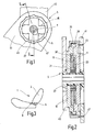
- a vehicle seat 1 for a motor vehicle has for the inclination adjustment of its backrest 3 on its two sides depending on a fitting 5, which is designed as a detent fitting, but could also be designed as a geared fitting.
- the two fittings 5 are connected to each other by means of a transmission rod 7 in gear connection.
- a rotationally fixed on the transmission rod 7 seated hand lever 9 is used for manual actuation of the fittings 5.
- the following directional information refers to the cylindrical coordinate system, which is defined by the horizontally and transversely to the direction of travel arranged transmission rod 7.
- the fitting 5 is similar in construction to that of the DE 101 05 282 A1 whose disclosure content is expressly included.
- Each fitting 5 has an approximately disk-shaped first fitting part 11 and also an approximately disk-shaped second fitting part 12.
- the first fitting part 11 fixed to the seat part by means of four guide and bearing segments 15 carries two tooth segments 17, which are pressed radially outwards by a spring-loaded eccentric 21 and pulled radially inwards again by a drive plate 23.
- the eccentric 21 sits on a transmission element 27 made of plastic, which in turn sits non-rotatably on the transmission rod 7.
- the second fitting part 12 is rotatable relative to the first fitting part 11, and that before installation in the vehicle seat 1 by 360 °.
- the second fitting part 12 In the case of a training of the fitting 5 as a self-locking gear fitting, the second fitting part 12 would be almost identical, but would be formed on the first fitting part 11, a gear - driven by a rotatable relative to him eccentric - perform a rolling movement on the ring gear 30 of the second fitting part 12 would, which presents itself as a rotary motion with superimposed wobbling motion.
- a Umklamm ceremoniessring hereinafter referred to briefly as ring 35 is disposed on the radially outwardly facing peripheral surface of the first fitting part 11 and the second fitting part 12, wherein the first fitting part 11 is firmly pressed into the ring 35.
- the ring 35 engages with a flanged edge, the second fitting part 12 radially.
- an intermediate ring 39 is preferably provided between the second fitting part 12 and ring 35. The fitting 5 would already be transportable in this state.
- a designated adapter 41 and a purpose-adapted second adapter 42 is attached to the fitting 5.
- the intended for attachment to the backrest 3 second adapter 42 is fixed by laser welding on the second fitting part 12 on the side remote from the first fitting part 11 in the axial direction.
- the intended for attachment to the seat part first adapter 41 is applied in the axial direction of the first fitting part 11 on the side facing away from the second fitting part 12, wherein it completely covers the first fitting part 11 to a central opening.
- the first adapter 41 has a larger opening has the diameter of the first fitting part 11 and the latter receives with this opening, wherein it rests on a shoulder formed by the ring 35.
- a circumferential (laser) weld seam 45 for joining is formed from the same direction coming through the material of the first adapter 41, the first fitting part 11 and the ring 35 through, so as Humanstechnaht, so that these three components are firmly connected by means of a welding operation ,
- a (circular) annular base line 47 which is defined by the contact surface of the ring 35 on the first fitting part 11, the weld seam 45 oscillates around this baseline 47 in the radial direction, ie viewed in an axial direction of view, it has a wave shape during it oscillates in the circumferential direction.
- a continuous weld seam 45 thus runs, except in the material of the first adapter 41, still partially in the material of the first fitting part 11 and in sections in the material of the ring 35, wherein the base line 47 is crossed several times.
- the said three components (first fitting part 11, ring 35, first adapter 41) are connected to one another by a single weld seam 45.
- the weld 45 is not formed continuously, but consists only of individual sections separated from each other, for example, the baseline 47 crossing sections, whereby further said three components are connected together.
- the oscillation of the weld 45 takes place periodically, that is to say with a certain symmetry, but in the present case deviates from a sinusoidal shape.
Landscapes
- Engineering & Computer Science (AREA)
- Aviation & Aerospace Engineering (AREA)
- Transportation (AREA)
- Mechanical Engineering (AREA)
- Seats For Vehicles (AREA)
- Chairs For Special Purposes, Such As Reclining Chairs (AREA)
Priority Applications (1)
| Application Number | Priority Date | Filing Date | Title |
|---|---|---|---|
| PL05716567T PL1737696T3 (pl) | 2004-04-17 | 2005-04-09 | Okucie do siedzenia samochodowego |
Applications Claiming Priority (2)
| Application Number | Priority Date | Filing Date | Title |
|---|---|---|---|
| DE102004018744A DE102004018744B3 (de) | 2004-04-17 | 2004-04-17 | Beschlag für einen Fahrzeugsitz |
| PCT/EP2005/003761 WO2005100079A2 (de) | 2004-04-17 | 2005-04-09 | Beschlag für einen fahrzeugsitz |
Publications (2)
| Publication Number | Publication Date |
|---|---|
| EP1737696A2 EP1737696A2 (de) | 2007-01-03 |
| EP1737696B1 true EP1737696B1 (de) | 2008-02-13 |
Family
ID=34813730
Family Applications (1)
| Application Number | Title | Priority Date | Filing Date |
|---|---|---|---|
| EP05716567A Expired - Lifetime EP1737696B1 (de) | 2004-04-17 | 2005-04-09 | Beschlag für einen fahrzeugsitz |
Country Status (6)
| Country | Link |
|---|---|
| US (1) | US7497520B2 (enExample) |
| EP (1) | EP1737696B1 (enExample) |
| JP (1) | JP4450852B2 (enExample) |
| DE (2) | DE102004018744B3 (enExample) |
| PL (1) | PL1737696T3 (enExample) |
| WO (1) | WO2005100079A2 (enExample) |
Families Citing this family (23)
| Publication number | Priority date | Publication date | Assignee | Title |
|---|---|---|---|---|
| DE102004010491B4 (de) * | 2004-03-04 | 2008-04-03 | Keiper Gmbh & Co.Kg | Beschlag für einen Fahrzeugsitz |
| DE102004041735B4 (de) * | 2004-08-28 | 2007-08-30 | Keiper Gmbh & Co.Kg | Beschlag für einen Fahrzeugsitz |
| JP4916155B2 (ja) † | 2004-12-28 | 2012-04-11 | デルタ工業株式会社 | リクライニング装置 |
| DE102006041917B3 (de) * | 2006-09-07 | 2008-01-17 | Keiper Gmbh & Co.Kg | Übertragungsvorrichtung für einen Fahrzeugsitz |
| DE102006062720A1 (de) * | 2006-10-27 | 2008-05-08 | Johnson Controls Gmbh | Neigungsversteller für einen Fahrzeugsitz |
| DE102007009172B4 (de) | 2007-02-21 | 2009-05-07 | Keiper Gmbh & Co. Kg | Beschlag für einen Fahrzeugsitz |
| JP5309665B2 (ja) * | 2008-04-08 | 2013-10-09 | トヨタ紡織株式会社 | 車両用シートの連結装置 |
| JP5315757B2 (ja) | 2008-04-08 | 2013-10-16 | トヨタ紡織株式会社 | 車両用シートの連結装置 |
| KR101260338B1 (ko) * | 2008-06-13 | 2013-05-06 | 브로제 파르쪼이크타일레 게엠베하 운트 코. 카게, 코부르크 | 조정 피팅 |
| JP5318484B2 (ja) | 2008-07-29 | 2013-10-16 | 富士機工株式会社 | 車両のシートリクライニング装置 |
| DE102008038581A1 (de) * | 2008-08-18 | 2010-02-25 | Keiper Gmbh & Co. Kg | Anordnung für einen Fahrzeugsitz |
| CA2727953C (en) | 2008-08-22 | 2017-05-16 | Magna Seating Inc. | Disc recliner with reduced backlash |
| JP5239631B2 (ja) * | 2008-08-26 | 2013-07-17 | トヨタ紡織株式会社 | 車両用シートの連結装置 |
| JP5338212B2 (ja) * | 2008-09-09 | 2013-11-13 | トヨタ紡織株式会社 | 車両用シートの連結装置 |
| BRPI0923930A2 (pt) * | 2009-01-13 | 2016-01-12 | Keiper Gmbh & Co Kg | assento para veiculo, em particular assento para veiculo a motor |
| DE102009013881A1 (de) * | 2009-03-16 | 2010-09-23 | Brose Fahrzeugteile Gmbh & Co. Kommanditgesellschaft, Coburg | Vorrichtung mit einem Beschlag und einer Adapterplatte sowie Verfahren zur Herstellung einer solchen Vorrichtung |
| DE102009041491B4 (de) * | 2009-09-10 | 2013-04-11 | Keiper Gmbh & Co. Kg | Beschlag für einen Fahrzeugsitz und Fahrzeugsitz |
| DE102011013163B4 (de) * | 2011-03-04 | 2014-05-15 | Keiper Gmbh & Co. Kg | Beschlag für einen Fahrzeugsitz |
| CN104185570B (zh) | 2011-10-06 | 2016-12-07 | 李尔公司 | 具有容易进入型释放的座椅斜倾装置及其制造方法 |
| US9919628B2 (en) * | 2013-02-25 | 2018-03-20 | Johnson Controls Components Gmbh & Co. Kg | Fitting for a vehicle seat, method for assembling a fitting for a vehicle seat, and vehicle seat |
| WO2016047562A1 (ja) * | 2014-09-22 | 2016-03-31 | テイ・エス テック株式会社 | 車両用シートフレーム及び車両用シート |
| JP6780454B2 (ja) * | 2016-11-09 | 2020-11-04 | トヨタ紡織株式会社 | 乗物シート用バックフレーム |
| FR3084302B1 (fr) | 2018-07-27 | 2020-07-24 | Faurecia Sieges Dautomobile | Mecanisme d'articulation, siege de vehicule comportant un tel mecanisme et procede de fabrication |
Family Cites Families (19)
| Publication number | Priority date | Publication date | Assignee | Title |
|---|---|---|---|---|
| JPS57140119A (en) * | 1981-02-26 | 1982-08-30 | Aisin Seiki Co Ltd | Nozzle of hot-air welder for bonding different resin members |
| JPS60180688A (ja) * | 1984-02-28 | 1985-09-14 | Toshiba Corp | 圧縮機におけるシリンダと軸受体との接合固定方法 |
| JP3496164B2 (ja) * | 1992-11-25 | 2004-02-09 | カイペル・ゲゼルシヤフト・ミツト・ベシユレンクテル ハフツング・ウント・コンパニ− | 座席の調節装置にある部材結合部の製造方法 |
| DE4330133A1 (de) * | 1993-09-06 | 1995-03-16 | Naue Johnson Controls Eng | Schienenführung für Fahrzeugsitze |
| US5573345A (en) | 1993-11-22 | 1996-11-12 | Keiper Recaro Gmbh & Co. | Connection of structural component parts in adjusting devices for seats, inparticular for motor vehicles seats |
| JPH09206969A (ja) * | 1996-01-31 | 1997-08-12 | Mazda Motor Corp | レーザヘリ溶接部材およびその溶接方法 |
| IT1294759B1 (it) * | 1996-09-06 | 1999-04-12 | Kobe Seiko Sho Anche Conosciut | Membro di giunzione per una struttura saldata |
| FR2761308B1 (fr) * | 1997-03-27 | 1999-06-25 | Faure Bertrand Equipements Sa | Siege pour vehicule automobile |
| US6060682A (en) * | 1997-11-13 | 2000-05-09 | Westbroek; Wido | Overlapping joint for laser welding of tailored blanks |
| US6321930B1 (en) * | 1999-09-20 | 2001-11-27 | Lockheed Martin Corporation | Cryogenic tank joint |
| DE19961696C1 (de) * | 1999-12-21 | 2001-04-19 | Keiper Gmbh & Co | Verfahren zum Verbinden zweier Teile eines Fahrzeugsitzes |
| DE10105282B4 (de) * | 2001-02-06 | 2005-03-24 | Keiper Gmbh & Co. Kg | Beschlag für einen Fahrzeugsitz |
| GB2389552B (en) * | 2001-04-27 | 2005-02-02 | Honda Motor Co Ltd | Laser beam welding method and apparatus |
| US6949154B2 (en) * | 2001-07-28 | 2005-09-27 | Boehringer Ingelheim Pharma Kg | Method and apparatus for sealing medicinal capsules |
| US6688000B2 (en) * | 2001-11-13 | 2004-02-10 | General Motors Corporation | Joining of tubular parts in a T-joint by riveting/brazing |
| US6640414B2 (en) * | 2002-01-23 | 2003-11-04 | General Motors Corporation | Method for attaching metal members |
| JP2003334680A (ja) * | 2002-05-22 | 2003-11-25 | Suzuki Motor Corp | 溶接方法及びこれを用いて接合された構造体 |
| FR2883812B1 (fr) * | 2005-04-01 | 2007-06-22 | Faurecia Sieges Automobile | Mecanisme d'articulation, son procede de fabrication et siege de vehicule comportant un tel mecanisme |
| DE102005026658B3 (de) * | 2005-06-09 | 2006-11-02 | Faurecia Autositze Gmbh & Co. Kg | Neigungsverstellbeschlag für die Rückenlehne eines Kraftfahrzeugsitzes |
-
2004
- 2004-04-17 DE DE102004018744A patent/DE102004018744B3/de not_active Expired - Fee Related
-
2005
- 2005-04-09 EP EP05716567A patent/EP1737696B1/de not_active Expired - Lifetime
- 2005-04-09 WO PCT/EP2005/003761 patent/WO2005100079A2/de not_active Ceased
- 2005-04-09 DE DE502005002836T patent/DE502005002836D1/de not_active Expired - Lifetime
- 2005-04-09 JP JP2007507728A patent/JP4450852B2/ja not_active Expired - Fee Related
- 2005-04-09 PL PL05716567T patent/PL1737696T3/pl unknown
-
2006
- 2006-10-16 US US11/582,054 patent/US7497520B2/en not_active Expired - Fee Related
Also Published As
| Publication number | Publication date |
|---|---|
| US20070035168A1 (en) | 2007-02-15 |
| DE502005002836D1 (de) | 2008-03-27 |
| WO2005100079A2 (de) | 2005-10-27 |
| EP1737696A2 (de) | 2007-01-03 |
| JP2007532217A (ja) | 2007-11-15 |
| PL1737696T3 (pl) | 2008-06-30 |
| US7497520B2 (en) | 2009-03-03 |
| DE102004018744B3 (de) | 2005-09-01 |
| WO2005100079A3 (de) | 2006-03-09 |
| JP4450852B2 (ja) | 2010-04-14 |
Similar Documents
| Publication | Publication Date | Title |
|---|---|---|
| EP1737696B1 (de) | Beschlag für einen fahrzeugsitz | |
| DE10105282B4 (de) | Beschlag für einen Fahrzeugsitz | |
| EP1713659B1 (de) | Beschlag für einen fahrzeugsitz | |
| DE102009041491B4 (de) | Beschlag für einen Fahrzeugsitz und Fahrzeugsitz | |
| EP2001704B1 (de) | Beschlag für einen fahrezugsitz | |
| DE102009039461B4 (de) | Beschlag für einen Fahrzeugsitz | |
| EP2419296B1 (de) | Antriebseinheit für einen fahrzeugsitz | |
| DE102010013092A1 (de) | Beschlag für einen Fahrzeugsitz | |
| DE102012012847B3 (de) | Beschlag für einen Fahrzeugsitz und Fahrzeugsitz | |
| DE112008001431T5 (de) | Beschlag für einen Fahrzeugsitz | |
| DE102009040504A1 (de) | Beschlag für einen Fahrzeugsitz | |
| DE102009041490A1 (de) | Beschlag für einen Fahrzeugsitz | |
| WO2010097160A1 (de) | Beschlag für einen fahrzeugsitz | |
| WO2011134584A1 (de) | Beschlag für einen fahrzeugsitz | |
| DE102009038562B3 (de) | Beschlag für einen Fahrzeugsitz sowie Fahrzeugsitz | |
| DE202010015143U1 (de) | Beschlag für einen Fahrzeugsitz | |
| DE102010035442B4 (de) | Verfahren zum Verbinden eines Beschlags mit einem Strukturteil eines Fahrzeugsitzes | |
| DE102009053250B4 (de) | Beschlag für einen Fahrzeugsitz und Fahrzeugsitz | |
| DE102004061062A1 (de) | Beschlag für einen Fahrzeugsitz | |
| WO2015055478A1 (de) | Fahrzeugsitz, insbesondere kraftfahrzeugsitz | |
| EP1813466B1 (de) | Gelenkbeschlag | |
| WO2013060443A1 (de) | Beschlag für einen fahrzeugsitz und fahrzeugsitz | |
| DE3130314A1 (de) | Gelenkbeschlag fuer sitze mit verstellbarer rueckenlehne, insbesondere kraftfahrzeugsitze | |
| EP3114295B1 (de) | Verriegelungssystem mit kontaktflächen | |
| DE102010022830B4 (de) | Verfahren zum Verschweißen zweier Bauteile |
Legal Events
| Date | Code | Title | Description |
|---|---|---|---|
| PUAI | Public reference made under article 153(3) epc to a published international application that has entered the european phase |
Free format text: ORIGINAL CODE: 0009012 |
|
| 17P | Request for examination filed |
Effective date: 20060112 |
|
| AK | Designated contracting states |
Kind code of ref document: A2 Designated state(s): DE FR GB PL |
|
| DAX | Request for extension of the european patent (deleted) | ||
| RBV | Designated contracting states (corrected) |
Designated state(s): DE FR GB PL |
|
| GRAP | Despatch of communication of intention to grant a patent |
Free format text: ORIGINAL CODE: EPIDOSNIGR1 |
|
| GRAS | Grant fee paid |
Free format text: ORIGINAL CODE: EPIDOSNIGR3 |
|
| GRAA | (expected) grant |
Free format text: ORIGINAL CODE: 0009210 |
|
| AK | Designated contracting states |
Kind code of ref document: B1 Designated state(s): DE FR GB PL |
|
| REG | Reference to a national code |
Ref country code: GB Ref legal event code: FG4D Free format text: NOT ENGLISH |
|
| REF | Corresponds to: |
Ref document number: 502005002836 Country of ref document: DE Date of ref document: 20080327 Kind code of ref document: P |
|
| REG | Reference to a national code |
Ref country code: PL Ref legal event code: T3 |
|
| ET | Fr: translation filed | ||
| PLBE | No opposition filed within time limit |
Free format text: ORIGINAL CODE: 0009261 |
|
| STAA | Information on the status of an ep patent application or granted ep patent |
Free format text: STATUS: NO OPPOSITION FILED WITHIN TIME LIMIT |
|
| 26N | No opposition filed |
Effective date: 20081114 |
|
| REG | Reference to a national code |
Ref country code: DE Ref legal event code: R082 Ref document number: 502005002836 Country of ref document: DE Representative=s name: VERTRETERANGABEN UNKLAR, DE |
|
| REG | Reference to a national code |
Ref country code: DE Ref legal event code: R082 Ref document number: 502005002836 Country of ref document: DE Effective date: 20140710 Representative=s name: VERTRETERANGABEN UNKLAR, DE Ref country code: DE Ref legal event code: R082 Ref document number: 502005002836 Country of ref document: DE Representative=s name: VERTRETERANGABEN UNKLAR, DE Effective date: 20120326 Ref country code: DE Ref legal event code: R081 Ref document number: 502005002836 Country of ref document: DE Owner name: JOHNSON CONTROLS COMPONENTS GMBH & CO. KG, DE Free format text: FORMER OWNER: KEIPER GMBH & CO. KG, 67657 KAISERSLAUTERN, DE Effective date: 20140710 Ref country code: DE Ref legal event code: R081 Ref document number: 502005002836 Country of ref document: DE Owner name: ADIENT LUXEMBOURG HOLDING S.A.R.L., LU Free format text: FORMER OWNER: KEIPER GMBH & CO. KG, 67657 KAISERSLAUTERN, DE Effective date: 20140710 Ref country code: DE Ref legal event code: R082 Ref document number: 502005002836 Country of ref document: DE Representative=s name: LIEDHEGENER, RALF, DIPL.-ING., DE Effective date: 20120326 Ref country code: DE Ref legal event code: R082 Ref document number: 502005002836 Country of ref document: DE Representative=s name: LIEDHEGENER, RALF, DIPL.-ING., DE Effective date: 20140710 Ref country code: DE Ref legal event code: R081 Ref document number: 502005002836 Country of ref document: DE Owner name: ADIENT LUXEMBOURG HOLDING S.A R.L., LU Free format text: FORMER OWNER: KEIPER GMBH & CO. KG, 67657 KAISERSLAUTERN, DE Effective date: 20140710 |
|
| REG | Reference to a national code |
Ref country code: FR Ref legal event code: PLFP Year of fee payment: 12 |
|
| REG | Reference to a national code |
Ref country code: DE Ref legal event code: R082 Ref document number: 502005002836 Country of ref document: DE Representative=s name: VERTRETERANGABEN UNKLAR, DE Ref country code: DE Ref legal event code: R081 Ref document number: 502005002836 Country of ref document: DE Owner name: ADIENT LUXEMBOURG HOLDING S.A.R.L., LU Free format text: FORMER OWNER: JOHNSON CONTROLS COMPONENTS GMBH & CO. KG, 67657 KAISERSLAUTERN, DE Ref country code: DE Ref legal event code: R082 Ref document number: 502005002836 Country of ref document: DE Representative=s name: LIEDHEGENER, RALF, DIPL.-ING., DE Ref country code: DE Ref legal event code: R081 Ref document number: 502005002836 Country of ref document: DE Owner name: ADIENT LUXEMBOURG HOLDING S.A R.L., LU Free format text: FORMER OWNER: JOHNSON CONTROLS COMPONENTS GMBH & CO. KG, 67657 KAISERSLAUTERN, DE |
|
| REG | Reference to a national code |
Ref country code: FR Ref legal event code: PLFP Year of fee payment: 13 |
|
| PGFP | Annual fee paid to national office [announced via postgrant information from national office to epo] |
Ref country code: PL Payment date: 20170330 Year of fee payment: 13 |
|
| PGFP | Annual fee paid to national office [announced via postgrant information from national office to epo] |
Ref country code: GB Payment date: 20170419 Year of fee payment: 13 Ref country code: DE Payment date: 20170430 Year of fee payment: 13 Ref country code: FR Payment date: 20170419 Year of fee payment: 13 |
|
| REG | Reference to a national code |
Ref country code: DE Ref legal event code: R082 Ref document number: 502005002836 Country of ref document: DE Representative=s name: LIEDHEGENER, RALF, DIPL.-ING., DE |
|
| REG | Reference to a national code |
Ref country code: DE Ref legal event code: R082 Ref document number: 502005002836 Country of ref document: DE Representative=s name: LIEDHEGENER, RALF, DIPL.-ING., DE Ref country code: DE Ref legal event code: R081 Ref document number: 502005002836 Country of ref document: DE Owner name: ADIENT LUXEMBOURG HOLDING S.A R.L., LU Free format text: FORMER OWNER: ADIENT LUXEMBOURG HOLDING S.A.R.L., LUXEMBOURG, LU |
|
| REG | Reference to a national code |
Ref country code: DE Ref legal event code: R119 Ref document number: 502005002836 Country of ref document: DE |
|
| GBPC | Gb: european patent ceased through non-payment of renewal fee |
Effective date: 20180409 |
|
| PG25 | Lapsed in a contracting state [announced via postgrant information from national office to epo] |
Ref country code: DE Free format text: LAPSE BECAUSE OF NON-PAYMENT OF DUE FEES Effective date: 20181101 |
|
| PG25 | Lapsed in a contracting state [announced via postgrant information from national office to epo] |
Ref country code: GB Free format text: LAPSE BECAUSE OF NON-PAYMENT OF DUE FEES Effective date: 20180409 |
|
| PG25 | Lapsed in a contracting state [announced via postgrant information from national office to epo] |
Ref country code: FR Free format text: LAPSE BECAUSE OF NON-PAYMENT OF DUE FEES Effective date: 20180430 |
|
| PG25 | Lapsed in a contracting state [announced via postgrant information from national office to epo] |
Ref country code: PL Free format text: LAPSE BECAUSE OF NON-PAYMENT OF DUE FEES Effective date: 20180409 |