EP1737232B1 - Prozessor zum Umwandeln von Bildsignale, entsprechendes Verfahren und Bildanzeigegerät - Google Patents
Prozessor zum Umwandeln von Bildsignale, entsprechendes Verfahren und Bildanzeigegerät Download PDFInfo
- Publication number
- EP1737232B1 EP1737232B1 EP06076713A EP06076713A EP1737232B1 EP 1737232 B1 EP1737232 B1 EP 1737232B1 EP 06076713 A EP06076713 A EP 06076713A EP 06076713 A EP06076713 A EP 06076713A EP 1737232 B1 EP1737232 B1 EP 1737232B1
- Authority
- EP
- European Patent Office
- Prior art keywords
- coefficient
- data sets
- data set
- class
- signal
- Prior art date
- Legal status (The legal status is an assumption and is not a legal conclusion. Google has not performed a legal analysis and makes no representation as to the accuracy of the status listed.)
- Expired - Lifetime
Links
- 238000000034 method Methods 0.000 title claims description 143
- 238000006243 chemical reaction Methods 0.000 title description 96
- 238000004519 manufacturing process Methods 0.000 claims description 267
- 238000012545 processing Methods 0.000 claims description 154
- 238000001514 detection method Methods 0.000 claims description 107
- 238000004364 calculation method Methods 0.000 claims description 68
- 238000003860 storage Methods 0.000 claims description 46
- 238000010606 normalization Methods 0.000 claims description 33
- 238000000605 extraction Methods 0.000 claims description 8
- 238000004590 computer program Methods 0.000 claims description 7
- 230000008569 process Effects 0.000 claims description 5
- 230000015572 biosynthetic process Effects 0.000 description 31
- 238000003786 synthesis reaction Methods 0.000 description 31
- 238000013139 quantization Methods 0.000 description 26
- 239000000284 extract Substances 0.000 description 20
- 238000012546 transfer Methods 0.000 description 11
- 238000004891 communication Methods 0.000 description 9
- 230000004044 response Effects 0.000 description 8
- 238000010586 diagram Methods 0.000 description 6
- 238000009826 distribution Methods 0.000 description 6
- 230000009467 reduction Effects 0.000 description 5
- 230000006870 function Effects 0.000 description 4
- 238000010408 sweeping Methods 0.000 description 3
- 230000003044 adaptive effect Effects 0.000 description 2
- 230000005540 biological transmission Effects 0.000 description 2
- 238000013144 data compression Methods 0.000 description 2
- 239000004973 liquid crystal related substance Substances 0.000 description 2
- 230000003321 amplification Effects 0.000 description 1
- 230000008859 change Effects 0.000 description 1
- 230000006866 deterioration Effects 0.000 description 1
- 238000011161 development Methods 0.000 description 1
- 230000004069 differentiation Effects 0.000 description 1
- 230000008030 elimination Effects 0.000 description 1
- 238000003379 elimination reaction Methods 0.000 description 1
- 238000003384 imaging method Methods 0.000 description 1
- 239000011159 matrix material Substances 0.000 description 1
- 238000003199 nucleic acid amplification method Methods 0.000 description 1
- 238000012163 sequencing technique Methods 0.000 description 1
- 230000005236 sound signal Effects 0.000 description 1
- 239000004575 stone Substances 0.000 description 1
- 230000001629 suppression Effects 0.000 description 1
- 230000001360 synchronised effect Effects 0.000 description 1
- 230000002194 synthesizing effect Effects 0.000 description 1
Images


Classifications
-
- H—ELECTRICITY
- H04—ELECTRIC COMMUNICATION TECHNIQUE
- H04N—PICTORIAL COMMUNICATION, e.g. TELEVISION
- H04N7/00—Television systems
- H04N7/01—Conversion of standards, e.g. involving analogue television standards or digital television standards processed at pixel level
-
- G—PHYSICS
- G06—COMPUTING; CALCULATING OR COUNTING
- G06T—IMAGE DATA PROCESSING OR GENERATION, IN GENERAL
- G06T3/00—Geometric image transformations in the plane of the image
- G06T3/40—Scaling of whole images or parts thereof, e.g. expanding or contracting
-
- G—PHYSICS
- G06—COMPUTING; CALCULATING OR COUNTING
- G06T—IMAGE DATA PROCESSING OR GENERATION, IN GENERAL
- G06T3/00—Geometric image transformations in the plane of the image
- G06T3/40—Scaling of whole images or parts thereof, e.g. expanding or contracting
- G06T3/4007—Scaling of whole images or parts thereof, e.g. expanding or contracting based on interpolation, e.g. bilinear interpolation
-
- H—ELECTRICITY
- H04—ELECTRIC COMMUNICATION TECHNIQUE
- H04N—PICTORIAL COMMUNICATION, e.g. TELEVISION
- H04N7/00—Television systems
- H04N7/01—Conversion of standards, e.g. involving analogue television standards or digital television standards processed at pixel level
- H04N7/0117—Conversion of standards, e.g. involving analogue television standards or digital television standards processed at pixel level involving conversion of the spatial resolution of the incoming video signal
- H04N7/012—Conversion between an interlaced and a progressive signal
-
- H—ELECTRICITY
- H04—ELECTRIC COMMUNICATION TECHNIQUE
- H04N—PICTORIAL COMMUNICATION, e.g. TELEVISION
- H04N7/00—Television systems
- H04N7/01—Conversion of standards, e.g. involving analogue television standards or digital television standards processed at pixel level
- H04N7/0125—Conversion of standards, e.g. involving analogue television standards or digital television standards processed at pixel level one of the standards being a high definition standard
-
- H—ELECTRICITY
- H04—ELECTRIC COMMUNICATION TECHNIQUE
- H04N—PICTORIAL COMMUNICATION, e.g. TELEVISION
- H04N7/00—Television systems
- H04N7/01—Conversion of standards, e.g. involving analogue television standards or digital television standards processed at pixel level
- H04N7/0135—Conversion of standards, e.g. involving analogue television standards or digital television standards processed at pixel level involving interpolation processes
- H04N7/0137—Conversion of standards, e.g. involving analogue television standards or digital television standards processed at pixel level involving interpolation processes dependent on presence/absence of motion, e.g. of motion zones
-
- H—ELECTRICITY
- H04—ELECTRIC COMMUNICATION TECHNIQUE
- H04N—PICTORIAL COMMUNICATION, e.g. TELEVISION
- H04N7/00—Television systems
- H04N7/01—Conversion of standards, e.g. involving analogue television standards or digital television standards processed at pixel level
- H04N7/0135—Conversion of standards, e.g. involving analogue television standards or digital television standards processed at pixel level involving interpolation processes
- H04N7/0145—Conversion of standards, e.g. involving analogue television standards or digital television standards processed at pixel level involving interpolation processes the interpolation being class adaptive, i.e. it uses the information of class which is determined for a pixel based upon certain characteristics of the neighbouring pixels
Definitions
- the invention relates to an information signal processor, a method for processing an information signal, an image signal processor and an image display apparatus using the same, a coefficient seed date production device used in the same and a method for producing coefficient seed data set, and an information-providing medium that are well suitable for use in conversion of, for example, an NTSC-system video signal into a High-Definition (hereinafter called Hi-vision) video signal.
- Hi-vision High-Definition
- the invention relates to an information signal processor and the like wherein coefficient data sets to be used in an estimation equation used in conversion of a first information signal into a second information signal are produced according to a production equation using both coefficient seed data sets, which are coefficient data sets in the production equation containing a predetermined parameter, and an input parameter value, thereby producing the coefficient data sets to be used in the estimation equation each data set corresponding to an arbitrary parameter value, without requiring a memory capable of storing a large number of coefficient data sets, and saving on the storage capacity of the memory.
- Hi-vision TV receiver uses 1125 scanning lines, which are at least twice the number of the scanning lines used in an NTSC-system receiver of 525. Also, the Hi-vision receiver has an aspect ratio of 9:16 as compared to the NTSC-system receiver's aspect ratio of 3:4. As such, the Hi-vision receiver can display an image with a higher resolution and realism than the NTSC-system one.
- the Hi-vision system has these excellent features, the Hi-vision receiver cannot display a Hi-vision image when an NTSC-system video signal is supplied as it is. The reason is that, as mentioned above, the NTSC system and the Hi-vision system have different standards.
- the applicant of this application previously disclosed a converter for converting the NTSC-system video signal into the Hi-vision video signal (see Japanese Patent Application No. Hei 6-205934 ).
- This converter extracts, from an NTSC-system video signal, pixel data sets of a block (region) of the NTSC-system video signal, which correspond to an objective position in a Hi-vision video signal, thereby deciding a class including the pixel data set of the objective position based on level distribution patterns of the pixel data sets in this block and then producing the pixel data set of the objective position corresponding to this class.
- a memory beforehand stores the coefficient data sets to be used in the estimation equation of each class so that as more classes are to be grouped, the number of the required coefficient data sets to be used in the estimation equation also increases, thus requiring a mass-capacity of the memory.
- an image according to the Hi-vision video signal has a fixed resolution and so cannot have a desired resolution corresponding to the image contents, unlike the conventional adjustment of contrast, sharpness, etc.
- a memory may beforehand store the coefficient data sets to be used in the estimation equation of every picture quality. This, however, leads to an increase in the amount of the required coefficient data sets to be used in the estimation equation, thus requiring a mass-capacity memory.
- EP975156 discloses an image signal converting apparatus in which pixels of an output signal are generated with an estimation equation using both the value of neighbouring pixels from the input signal and coefficient data received from a coefficient data memory.
- EP1001353 is concerned with an interpolation processing technique applied to a personal computer to prevent picture quality deterioration arising. It generates weighting coefficients in real time in response to phase information which is a result of phase comparison between a clock signal synchronised with the original pixels and a predetermined clock signal and conversion ratio information that varies with the size of the image that is to be displayed.
- the coefficient seed data set thus obtained beforehand which is coefficient data set in the production equation for producing the coefficient data set used in the estimation equation, is stored in the storage means and the production equation contain a predetermined parameter.
- a parameter decides a quality (resolution, noise suppression degree, etc.) of an output based on the second information signal or corresponds to a class including the informational data set of the objective position in the second information signal.
- the coefficient seed data set stored in the storage means and the value of the input parameter are used to produce the coefficient data set used in the estimation equation according to the production equation wherein the coefficient data set used in the estimation equation corresponds to the value of the input parameter. Then, this coefficient data set and second plural informational data sets are used to generate the informational data set of the objective position according to the estimation equation.
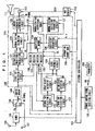
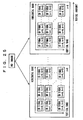
- FIG. 1 shows a configuration of a TV receiver 100 according to an embodiment of the invention.
- the TV receiver 100 receives a 525i signal as a Standard Definition (SD) signal from a broadcast signal and then converts this 525i signal into a 525p or 1050i signal as a High Definition (HD) signal to display an image by means of the 525p or 1050i signal.
- SD Standard Definition
- HD High Definition
- the 525i signal refers to an interlacing-system image signal having 525 lines
- the 525p signal refers to a progressive-system (non-interlacing-system) image signal having 525 lines
- the 1050i signal refers to an interlacing-system image signal having 1050 lines.
- the TV receiver 100 comprises a system controller 101 with a microcomputer for controlling the operations of the overall system, and a remote control signal receiving circuit 102 for receiving a remote control signal.
- the remote control signal receiving circuit 102 is connected, in configuration, to the system controller 101, and it is constituted so as to receive a remote control signal RM which a remote control transmitter 200 transits when the user operates the transmitter 200 and the to supply the system controller 101 with an operation signal corresponding to the signal RM.
- the TV receiver 100 also comprises a reception antenna 105, a tuner 106 for receiving a broadcast signal (RF modulated signal) captured by the reception antenna 105 and performing processing such as channel selection processing, intermediate-frequency amplification processing, wave detection processing to obtain the above-mentioned SD signal Va (525i signal), an external input terminal 107 for inputting an external SD signal Vb (525i signal), a transfer switch 108 for selectively transmitting any one of the SD signals Va and Vb, and a buffer memory 109 for temporarily storing the SD signal received from the transfer switch 108.
- processing such as channel selection processing, intermediate-frequency amplification processing, wave detection processing to obtain the above-mentioned SD signal Va (525i signal)
- an external input terminal 107 for inputting an external SD signal Vb (525i signal
- a transfer switch 108 for selectively transmitting any one of the SD signals Va and Vb
- a buffer memory 109 for temporarily storing the SD signal received from the transfer switch 108.
- the SD signal Va transmitted from the tuner 106 is supplied to the a-side fixed terminal of the transfer switch 108, while the SD signal Vb received through the external input terminal 107 is supplied to the b-side fixed terminal of the transfer switch 108.
- the system controller 101 controls the transfer operations of the transfer switch 108.
- the TV receiver 100 comprises an image signal processing section 110 for converting the SD signal (525i signal) temporarily stored in the buffer memory 109 into the HD signal (525p or 1050i signal), a display section 111 for displaying an image produced by means of the HD signal received from the image signal processing section 110, an On-Screen Display (OSD) circuit 112 for generating a display signal SCH for displaying characters, graphics, etc. on a screen of the display section 111, and a synthesizer 113 for synthesizing the displays signal SCH and the HD signal received from the image signal processing section 110 to then supply it to the display section 111.
- OSD On-Screen Display
- the display section 111 comprises a Cathode Ray Tube (CRT) or a flat panel display such as a Liquid Crystal Display (LCD). Also, the OSD circuit 112 generates the display signal SCH under the control of the system controller 101.
- CTR Cathode Ray Tube
- LCD Liquid Crystal Display
- the transfer switch 108 is connected to the a-side terminal under the control of the system controller 101 so that the SD signal Va can be transmitted from the transfer switch 108. If the user operates the remote control transmitter 200 to select a mode in which an image according to the SD signal Vb received through the external input terminal 107 is displayed, the transfer switch 108 is connected to the b-side terminal under the control of the system controller 101 so that the SD signal Vb can be transmitted from the transfer switch 108.
- the SD signal (525i signal) thus transmitted from the transfer switch 108 is recorded on the buffer memory 109, which temporarily stores it. Then, the SD signal temporarily stored in the buffer memory 109 is supplied to the image signal processing section 110, which converts it into an HD signal (525p or 1050i signal). That is, the image signal processing section 110 obtains pixel data sets constituting the HD signal (hereinafter called "HD pixel data sets") from pixel data sets constituting the SD signal (hereinafter called "SD pixel data sets"). In this case, the user can select either the 525p signal or the 1050i signal when he or she operates the remote control transmitter 200.
- the HD signal transmitted from the image signal processing section 110 is supplied through the synthesizer 113 to the display section 111, which then displays an image based on the HD signal on its screen.
- the user can operate the remote control transmitter 200 to adjust the horizontal and vertical resolutions of the image displayed on the screen of the display section 111 smoothly without steps as mentioned above.
- the image signal processing section 110 calculates HD pixel data sets according to an estimation equation, which will be described later.
- coefficient data sets to be used in this estimation equation the data sets corresponding to parameters h and v for deciding the respective horizontal and vertical resolutions adjusted by the user through operations of the remote control transmitter 200 are produced according to a production equation containing these parameters h, v and are used.
- the horizontal and vertical resolutions of the image based on the HD signal transmitted from the image signal processing section 110 result in a correspondence with the adjusted parameters h and v, respectively.
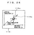
- FIG. 2 shows one example of a user interface for adjusting the parameters h and v.
- the display section 111 displays the adjustment screen 115 as OSD display wherein the adjustment position of the parameter h and v is indicated by a start-marked icon 115a.
- the remote control transmitter 200 comprises a joystick 200a as user operation means.
- FIG. 3 shows an expanded part of the adjustment screen 115.
- the icon 115a moves from side to side, the value of the parameter h for deciding the horizontal resolution can be adjusted, while when it moves up and down, the value of the parameter v for deciding the vertical resolution can be adjusted.
- the user can easily adjust the values of the parameters h and/or v with referencing the contents of the adjustment screen 115 displayed on the display section 111.
- the remote control transmitter 200 may be equipped with, in place of the joystick 200a, any other pointing device such as a mouse or a track ball. Further, the values of the parameters h and v adjusted by the user may be displayed digitally on the adjustment screen 115.
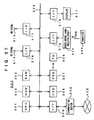
- the image signal processing section 110 includes first through third tap selection circuits 121 to 123 each for selectively extracting, from the SD signal (525i signal) stored in the buffer memory 109, plural SD pixel data sets located on a periphery of an objective position in the HD signal (1050i or 525p signal) and for transmitting them.
- the first tap selection circuit 121 selectively extracts SD pixel data sets for use in prediction (hereinafter called “prediction tap”).
- the second tap selection circuit 122 selectively extracts SD pixel data sets for use in class grouping (hereinafter called “space class tap”) corresponding to the distribution pattern of the levels of SD pixel data sets.
- the third tap selection circuit 123 selectively extracts SD pixel data sets for use in class grouping (hereinafter called "motion class tap”) corresponding to motion. Note here that, if the space class is decided using SD pixel data sets that belong to a plurality of fields, this space class also contains motion information.
- FIG. 4 shows a pixel position relationship of odd-number (o) fields of a certain frame (F) between the 525i signal and the 525p signal.
- a larger dot represents a pixel of the 525i signal and a smaller dot represents a pixel of the 525p signal to be transmitted.
- e even-number
- a line of the 525i signal is shifted by a 0.5 line in space.
- L1 line data sets L1 at the same position as the line of the 525i signal
- line data sets L2 at the intermediate line between the upper and lower lines of the 525i signal.
- Each line of the 525p signal has pixels twice as many as those of each line of the 525i signal.
- FIG. 5 is an illustration explaining a pixel position relationship of a certain frame (F) between the 525i signal and the 1050i signal.
- a solid line indicates the pixel position, of an odd-number (o) field and a broken line indicates that of an even-number (e) field.
- a larger dot represents a pixel of the 525i signal and a smaller dot represents a pixel of the 1050i signal to be transmitted.
- the pixel data sets of the 1050i signal are there present line data sets L1 and L1' near the line of the 525i signal and line data sets L2 and L2' remote from the line of the 525i signal.
- the L1 and L2, herein, represent line data sets of an odd-number field and the L1' and L2' represent line data sets of an even-number field.
- Each line of the 1050i signal also has pixels twice as many as those of each line of the 525i signal.
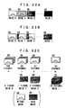
- FIGS. 6 and 7 show specific examples of a prediction tap (SD pixel) selected by the first tap selection circuit 121 when the 525i signal is converted into the 525p signal.
- FIGS. 6 and 7 show vertical pixel position relationship between the odd-number (o) and even-number (e) fields of time-wise consecutive frames F-1, F, and F+1.
- the prediction tap used when line data set L1 or L2 of a field F/o is predicted includes SD pixels T1, T2, and T3 that are contained in the next field F/e and that are present space-wise in the vicinity of a pixel (that is, pixel of an objective position) of a 525p signal to be produced, SD pixels T4, T5, and T6 that are contained in the field F/o and that are present space-wise in the vicinity of the pixel of the 525p signal to be produced, SD pixels T7, T8, and T9.that are contained in the previous field F-1/e and that are present space-wise in the vicinity of the pixel of the 525p signal to be produced, and SD pixel T10 that is contained in the further previous field F-1/o and that is present space-wise in the vicinity of a pixel of the 525p signal to be produced.
- a prediction tap used when line data set L1 or L2 of a field F/e is produced includes SD pixels T1, T2, and T3 that are contained in the next field F+1/o and that are present space-wise in the vicinity of a pixel of the 525p signal to be produced, SD pixels T4, T5, and T6 that are contained in the field F/e and that are present space-wise in the vicinity of a pixel of the 525p signal to be produced, SD pixels T7, T8, and T9 that are contained in the previous field F/o and that are present space-wise in the vicinity of a pixel of the 525p signal to be produced, and SD pixel T10 that is contained in the further previous field F-1/e and that is present space-wise in the vicinity of a pixel of the 525p signal to be produced.
- SD pixel T9 may not be selected as a prediction tap when line data set L1 is predicted, while SD pixel T4 may not be selected as a prediction tap when line data set L2 is predicted.
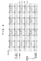
- FIGS. 8 and 9 show specific examples of a prediction tap (SD pixel) selected by the first tap selection circuit 121 when the 525i signal is converted into the 1050i signal.
- FIGS. 8 and 9 also show vertical pixel position relationship between the odd-number (o) and even-number (e) fields of time-wise consecutive frames F-1, F, and F+1.
- as prediction tap used when line data set L1 or L2 of a field F/o is predicted includes SD pixels T1 and T2 that are contained in the next field F/e and that are present space-wise in the vicinity of a pixel (that is, pixel of an objective position) of a 1050i signal to be produced, SD pixels T3, T4, T5, and T6 that are contained in the field F/o and that are present space-wise in the vicinity of a pixel of the 1050i signal to be produced, and SD pixels T7 and T8 that are contained in the previous field. F-1/e and that are present space-wise in the vicinity of a pixe-1 of the 1050i signal to be produced.
- a prediction tap used when line data set L1' or L2' of the field F/e is predicted includes SD pixels T1 and T2 that are contained in the next field F+1/o and that are present space-wise in the vicinity of a pixel of a 1050ip signal to be produced, SD pixels T3, T4, T5, and T6 that are contained in the field F/e and that are present space-wise in the vicinity of a pixel of the 1050i signal to be produced, and SD pixels T7 and T8 that are contained in the previous field F/o and that are present space-wise in the vicinity of a pixel of the 1050i signal to be produced.
- SD pixel T6 may not be selected as a prediction tap when line data set L1' is predicted, while SD pixel T3 may not be selected as a prediction tap when line data set L2' is predicted.
- one or more SD pixels in the horizontal direction may be selected as a prediction tap.
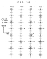
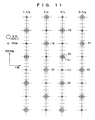
- FIGS. 10 and 11 show specific examples of a space class tap (SD pixel) selected by the second tap selection circuit 122 when the 525i signal is converted into the 525p signal.
- FIGS. 10 and 11 show also the vertical pixel position relationship between odd-number (o) and even-number fields of time-wise consecutive frames F-1, F, and F+1.
- a space class tap used when line data set L1 or L2 of a field F/o is predicted includes SD- pixels T1 and T2 that are contained in the next field F/e and that are present space-wise in the vicinity of a pixel (that is, pixel of an objective position) of a 525p signal to be produced, SD pixels T3, T4, and T5 that are contained in the field F/o and that are present space-wise in the vicinity of a pixel of the 525p signal to be produced, and SD pixels T6 and T7 that are contained in the previous field F-1/e and that are present space-wise in the vicinity of a pixel of the 525p signal to be produced.
- a space class tap used when line data set L1 or L2 of a field F/e is predicted includes SD pixels T1 and T2 that are contained in the next field F+1/o and that are present space-wise in the vicinity of a pixel of the 525p signal to be produced, SD pixels T3, T4 and T5 that are contained in the field F/e and that are present space-wise in the vicinity of a pixel of the 525p signal to be produced, and SD pixels T6 and T7 that are contained in the previous field F/o and that are present space-wise in the vicinity of a pixel of the 525p signal to be produced.
- SD pixel T7 may not be selected as a space class tap when line data set L1 is predicted, while SD pixel T6 may not be selected as a space class tap when line data set L2 is predicted.
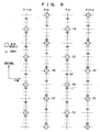
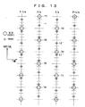
- FIGS. 12 and 13 show specific examples of a space class tap (SD pixel) selected by the second tap selection circuit 122 when the 525i signal is converted into the 1050i signal.
- FIGS. 12 and 13 also show the vertical pixel position relationship between odd-number (o) and even-number fields of time-wise consecutive frames F-1, F, and F+1.
- a space class tap used when line data set L1 or L2 of a field F/o is predicted includes SD pixels T1, T2, and T3 that are contained in the field F/o and that are present space-wise in the vicinity of a pixel (that is, pixel of an objective position) of a 1050i signal to be produced, and SD pixels T4, T5, T6, and T7 that are contained in the previous field F-1/e and that are present space-wise in the vicinity of a pixel of the 1050i signal to be produced.
- a space class tap used when line data set L1' or L2' of a field F/e is predicted includes SD pixels T1, T2, and T3 that are contained in the field F/e and that are present space-wise in the vicinity of a pixel of the 1050i signal to be produced, and SD pixels T4, T5, T6, and T7 that are contained in the previous field F/o and that are present space-wise in the vicinity of a pixel of the 1050i signal to be produced.
- SD pixel T7 may not be selected as a space class tap when line data set L1' is predicted, while SD pixel T4 may not be selected as a space class tap when line data set L2' is predicted.
- one or more SD pixels in the horizontal direction may be selected as a space class tap.
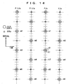
- FIG. 14 shows a specific example of a motion class tap (SD pixel) selected by the third tap selection circuit 123 when the 525i signal is converted into the 525p signal.
- FIG. 14 also shows a vertical pixel position relationship between odd-number (o) and even-number (e) fields of time-wise consecutive frames F-1 and F. As shown in FIG.
- a motion class tap used when line data set L1 or L2 of a field F/o is predicted includes SD pixels n2, n4, and n6 that are contained in the next field F/e and that are present space-wise in the vicinity of a pixel (that is, pixel of an objective position) of a 525p signal to be produced, SD pixels n1, n3, and n5 that are contained in the field F/o and that are present space-wise in the vicinity of a pixel of the 525p signal to be produced, SD pixels m2, m4, and m6 that are contained in the previous field F-1/e and that are present space-wise in the vicinity of a pixel of the 525p signal to be produced, and SD pixels m1, m3, and m5 that are contained in the further previous field F-1/o and that are present space-wise in the vicinity of a pixel of the 525p signal to be produced.
- the vertical position of each of the SD pixels n1 through n6 coincides with that of each of the
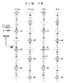
- FIG. 15 shows a specific example of a motion class tap (SD pixel) selected by the third tap selection circuit 123 when the 525i signal is converted into the 1050i signals.
- FIG. 15 also shows the vertical pixel position relationship between odd-number (o) and even-number (e) fields of time-wise consecutive frames F-1 and F. As shown in FIG.
- a motion class tap used when line data set L1 or L2 of a field F/o is predicted includes SD pixels n2, n4, and n6 that are contained in the next field F/e and that are present space-wise in the vicinity of a pixel of a 1050i signal to be produced, SD pixels n1, n3, and n5 that are contained in the field F/o and that are present space-wise in the vicinity of the pixel of the 1050i signal to be produced, SD pixels m2, m4, and m6 that are contained in the previous field F-1/e and that are present space-wise in the vicinity of a pixel of the 1050i signal to be produced, and SD pixels m1, m3, and m5 that are contained in the further previous field F-1/o and that are present space-wise in the vicinity of a pixel of the 1050i signal to be produced.
- the vertical position of each of the SD pixels n1 through n6 coincides with that of each of the SD pixels m1 through m6, respectively.
- the image signal processing section 110 also includes a space class detection circuit 124 for detecting a level distribution pattern of the data sets (SD pixel data sets) of a space class tap selectively extracted by the second tap selection circuit 122, detecting a space class based on this level distribution pattern, and then transmitting their class information.
- a space class detection circuit 124 for detecting a level distribution pattern of the data sets (SD pixel data sets) of a space class tap selectively extracted by the second tap selection circuit 122, detecting a space class based on this level distribution pattern, and then transmitting their class information.
- the space class detection circuit 124 performs a calculation such that, for example, the SD pixel data sets are compressed from eight bit-data into two bit-data.
- the space class detection circuit 124 then transmits the compressed data sets corresponding to each of the SD pixel data sets as class information of the space class.
- the data compression is performed according to Adaptive Dynamic Range Coding (ADRC).
- ADRC Adaptive Dynamic Range Coding
- the information may be compressed according to DPCM (prediction coding), VQ (Vector Quantization), etc.
- ADRC adaptive re-quantization method for high-performance coding employed in a Video Tape Recorder (VTR)
- VTR Video Tape Recorder
- Equation (1) can be calculated on each of the SD pixel data sets ki as space class tap data sets to obtain a re-quantization code qi as compressed data sets.
- qi ki - MIN + 0.5 ⁇ .2 P / DR
- Equation (1) the portion enclosed with [] means truncation processing. If SD pixel data sets of Na are given as the space class tap data sets, term, "i" indicates 1 through Na.
- the image signal processing section 110 also includes a motion class detection circuit 125 for detecting a motion class for mainly representing a degree of motion from data sets (SD pixel data sets) of a motion class tap selectively extracted by the third tap selection circuit 123 and then transmitting their class information.
- a motion class detection circuit 125 for detecting a motion class for mainly representing a degree of motion from data sets (SD pixel data sets) of a motion class tap selectively extracted by the third tap selection circuit 123 and then transmitting their class information.
- the motion class detection circuit 125 calculates inter-frame differences from the data sets (SD pixel data sets) mi and ni of the motion class tap selectively extracted by the third tap selection circuit 123 and then performs threshold processing on an average value of the absolute values of thus calculated differences to detect a motion class, which is an index of the motion. That is, the motion class detection circuit 125 calculates an average value AV of the absolute values of the differences according to following Equation (2).
- Nb in the Equation (2) is six.
- the motion class detection circuit 125 compares thus calculated average value AV to one or a plurality of threshold values, thus obtaining motion information MV of a motion class.
- the image signal processing section 110 includes a class synthesis circuit 126 for obtaining a class code CL indicating a class including pixel data set of an HD signal to be produced (525p or 1050i signal), that is, pixel data set of an objective position, based on a re-quantization code qi as the class information of the space class received from the space class detection circuit 124 and the motion information MV of the motion class received from the motion class detection circuit 125.
- a class code CL indicating a class including pixel data set of an HD signal to be produced (525p or 1050i signal
- a re-quantization code qi as the class information of the space class received from the space class detection circuit 124 and the motion information MV of the motion class received from the motion class detection circuit 125.
- the class synthesis circuit 126 calculates the class code CL according to following Equation (3).
- Na indicates a number of data sets (SD pixel data sets) of the space class tap and P indicates a number of re-quantization bits by means of the ADRC.
- the image signal processing section 110 includes registers 130-133 and a coefficient memory 134. Operations of a later-described linear-sequential conversion circuit 129 need to be switched according to a case of transmitting the 525p signal and a case of transmitting the 1050i signal.
- the register 130 stores operation specification information for specifying the operations of the linear-sequential conversion circuit 129.
- the linear-sequential conversion circuit 129 operates according to the operation specification information received from the register 130.
- the register 131 stores tap position information on the prediction tap selected by the first tap selection circuit 121.
- the first tap selection circuit 121 selects the prediction tap on the basis of the tap position information received from the register 131. For example, a plurality of SD pixels that may possibly be selected is given numbers for specification, and on the basis of the tap position information, a number of the SD pixels to be selected is specified. This holds true also with the following tap position information.
- the register 132 stores tap position information of the space class tap selected by the second tap selection circuit 122.
- the second tap selection circuit 122 selects the space class tap on the basis of the tap position information received from the register 132.
- the register 132 stores tap position information A in a case of relatively small motion and tap position information B in a case of relatively large motion. Which one of these pieces of the tap position information A and B is to be supplied to the second tap selection circuit 122 is selected according to the motion information MV of the motion class received from the motion class detection circuit 125.
- the tap position information A is supplied to the second tap selection circuit 122, which in turn selects such a space class tap as to cover a plurality of fields as shown in FIGS. 10-13 .
- the tap position information B is supplied to the second tap selection circuit 122, which in turn selects such a space class tap as to be only SD pixel, which is not shown, that exists in the same field as that including a pixel to be produced.
- the above-mentioned register 131 may store the tap position information in the case of relatively small motion and the tap position information in the case of relatively large motion, to select the tap position information to be supplied to the first tap selection circuit 121 based on the motion information MV of the motion class received from the motion class detection circuit 125.
- the register 133 stores tap position information of the motion class tap selected by the third tap selection circuit 123.
- the third tap selection circuit 123 selects the motion class tap on the basis of the tap position information received from the register 133.
- the coefficient memory 134 stores coefficient data sets to be used in an estimation equation used in a later-described estimation/prediction calculation circuit 127.
- the coefficient data sets are used as information for converting the 525i signal as an SD signal into the 525p or 1050i signal as an HD signal.
- the coefficient memory 134 receives the class code CL, as read-out address information, from the above-mentioned class synthesis circuit 126, and transmits coefficient data sets corresponding to the class code CL to the estimation/prediction calculation circuit 127.
- the image signal processing section 110 includes an information memory bank 135.
- the information memory bank 135 beforehand accumulates therein operation specification information to be stored in the register 130 and tap position information to be stored in the registers 131-133.
- the information memory bank 135 beforehand accumulates therein first operation specification information to allow the linear-sequential conversion circuit 129 to transmit the 525p signal and second operation specification information to allow the linear-sequential conversion circuit 129 to transmit the 1050i signal.
- the user can operate the remote control transmitter 200 to select a first conversion method of transmitting the 525p signal as the HD signal or a second conversion method of transmitting the 1050i signal as the HD signal.
- information memory bank 135 information of the selected conversion method is supplied through the system controller 101, and according to this selection information, the first or second operation specification information is loaded from the information memory bank 135 to the register 130.
- the information memory bank 135 beforehand accumulates therein first tap position information that corresponds to the first conversion method (525p) and second tap position information that corresponds to the second conversion method (1030i). From this information memory bank 135, the first or second tap position information is loaded to the register 131 according to the above-mentioned conversion method selection information.
- the information memory bank 135 beforehand accumulates therein first tap position information that corresponds to the first conversion method (525p) and second tap position information that corresponds to the second conversion method (1050i).
- the first and second tap position information consists of tap position information in a case of relatively small motion and that in a case of relatively large motion, respectively.
- the first or second tap position information is loaded from this information memory bank 135 to the register 132 according to the above-mentioned conversion method selection information.
- the information memory bank 1-35 beforehand accumulates therein first tap position information that corresponds to the first conversion method (525p) and second tap position information that corresponds to the second conversion method (1050i). From this information memory bank 135, the first or second tap position information is loaded to the register 133 according to the above-mentioned conversion method selection information.
- the information memory bank 135 beforehand accumulates coefficient seed data sets, for each class, each corresponding to the first and second conversion methods, respectively.
- the coefficient seed data sets are coefficient data sets in a production equation for producing the coefficient data sets stored in the above-mentioned coefficient memory 134.
- the later-described estimation/prediction calculation circuit 127 calculates HD pixel data sets y to be produced according to an estimation equation of following Equation (4) based on data sets xi of a prediction tap (SD pixel data sets) and coefficient data sets Wi read out of the coefficient memory 134.
- n in the Equation (4) is 10.
- W 1 w 10 + w 11 ⁇ v + w 12 ⁇ h + w 13 ⁇ v 2 + w 14 ⁇ vh + w 15 ⁇ h 2 + w 16 ⁇ v 3 + w 17 ⁇ v 2 ⁇ h + w 18 ⁇ vh 2 + w 19 ⁇ h 3
- the information memory bank 135 stores therein such the coefficient seed data sets w 10 through w n9 , which are the coefficient data sets in this production equation, for each conversion method and for each class. How to produce the coefficient seed data sets will be described later.
- To this coefficient production circuit 136 are loaded the class-specific coefficient seed data sets corresponding to the first or second conversion method employed according to the above-mentioned conversion method selection information, from the information memory bank 135.
- the system controller 101 supplies this coefficient production circuit 136 with values of the parameters h and v.
- the coefficient production circuit 136 produces the coefficient data sets Wi for each class in, for example, each vertical blanking period.
- the normalization coefficient memory 138 receives the class code CL from the above-mentioned class synthesis circuit 126 as read-out address information, and the normalized coefficient S corresponding to the class code CL is read out of this normalization coefficient memory 138 and supplied to the normalization calculation circuit 128, which will be described later.
- the image signal processing section 110 includes the estimation/prediction calculation circuit 127 for calculating pixel data set of an HD signal to be produced (that is, pixel data set of an objective position), based on the data sets (SD pixel data sets) xi of the prediction tap selectively extracted by the first tap selection circuit 121 and the coefficient data sets Wi read out of the coefficient memory 134.
- the estimation/prediction calculation circuit 127 for calculating pixel data set of an HD signal to be produced (that is, pixel data set of an objective position), based on the data sets (SD pixel data sets) xi of the prediction tap selectively extracted by the first tap selection circuit 121 and the coefficient data sets Wi read out of the coefficient memory 134.
- this estimation/prediction calculation circuit 127 It is necessary for this estimation/prediction calculation circuit 127 to produce line data sets L1 at the same line as that of the 525i signal and line data sets L2 at the intermediate position between the upper and lower lines of the 525i signal in odd-number (o) and even-number (e) fields, and also to double the number of pixels in each line with reference to FIG. 4 when transmitting the 525p signals.
- this estimation/prediction calculation circuit 127 it is necessary for this estimation/prediction calculation circuit 127 to produce line data sets L1 at the same line as that of the 525i signal and line data sets L2 at the intermediate position between the upper and lower lines of the 525i signal in odd-number (o) and even-number (e) fields, and also to double the number of pixels in each line with reference to FIG. 4 when transmitting the 525p signals.
- o odd-number
- e even-number
- this estimation/prediction calculation circuit 127 it is necessary for this estimation/prediction calculation circuit 127 to produce line data sets L1 and L1' near the line of the 525i signal and line data sets L2 and L2' remote from the line of the 525i signal in odd-number (o) and even-number (e) fields and also to double the number of pixels in each line when transmitting the 1050i signal.
- the estimation/prediction calculation circuit 127 simultaneously produces data sets of four pixels that constitute the HD signal. For example, each of the data sets of four pixels is simultaneously produced using the estimation equations having different coefficient data sets, which are supplied from the coefficient memory 134. In this case, the estimation/prediction calculation circuit 127 calculates HD pixel data sets y to be produced according to the above Equation (4) based on the data sets (SD pixel data sets) xi of the prediction tap and coefficient data sets Wi read out of the coefficient memory 134.
- the fluctuations can be removed by normalization at the normalization calculation circuit 128.
- the image signal processing section 110 includes the linear-sequential conversion circuit 129 for performing line speed-doubling processing on a horizontal period so as to be a half period thereof and for linearly sequencing line data sets L1 and L2 (L1' and L2') received from the normalization calculation circuit 128 through the estimation/prediction calculation circuit 127.
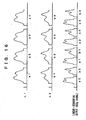
- FIG. 16 shows line speed-doubling processing for transmitting the 525p signal using an analog wave.
- the estimation/prediction calculation circuit 127 produces the line data sets L1 and L2.
- the line data sets L1 include lines a1, a2, a3 ... in this order, while the line data sets L2 include lines b1, b2, b3 ... in this order.
- the linear-sequential conversion circuit 129 compresses each of these line data sets in the time-axis direction by half to then select thus compressed line data sets alternately, thus forming linear-sequential outputs a0, b0, a1, b1...
- the linear-sequential conversion circuit 129 when transmitting the 1050i signal, the linear-sequential conversion circuit 129 generates a linear sequential output in order to satisfy the interfacing relationship between the odd-number and even-number fields.
- the linear-sequential conversion circuit 129 therefore, needs to switch the operation between transmitting of the 525p signal and transmitting of the 1050i signal.
- the concerned operation specification information is supplied from the register 130 as mentioned above.
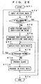
- the second tap selection circuit 122 Based on the SD signal (525i signal) stored in the buffer memory 109, the second tap selection circuit 122 selectively extracts data sets (SD pixel data sets) of a space class tap. In this case, the second tap selection circuit 122 selects a tap based on the tap position information, which is supplied from the register 132, corresponding to a user-selected conversion method and a motion class detected by the motion class detection circuit 125.
- Data sets (SD pixel data sets) of the space class tap thus extracted selectively by the second tap selection circuit 122 are supplied to the space class detection circuit 124.
- This space class detection circuit 124 performs ADRC processing on each of the SD pixel data sets given as the data sets of the space class tap to thereby obtain a re-quantization code qi as the class information of the space class (class grouping for mainly indicating a waveform in the space)(see the Equation (1)).
- the third tap selection circuit 123 selectively extracts data sets (SD pixel data sets) of a motion class tap. In this case, the third tap selection circuit 123 selects a tap based on the tap position information, which is supplied from the register 133, corresponding to the user-selected conversion method-.
- Data sets (SD pixel data sets) of the motion class tap thus extracted selectively by the third tap selection circuit 123 are supplied to the motion class detection circuit 125.
- This motion class detection circuit 125 obtains motion information MV of the motion class (class grouping for mainly indicating a degree of motion) from each of the SD pixel data sets given as data sets of the motion class tap..
- This motion information MV and the above-mentioned re-quantization code qi are supplied to the class synthesis circuit 126.
- This class synthesis circuit 126 in turn obtains the class code CL indicating a class including pixel data set (pixel data set of an objective position) of the HD signal (525p or 1050i signal) to be produced on the basis of this motion information MV and the re-quantization code qi (see the Equation (3)).
- This class code CL is then supplied as read-out address information to the coefficient memory 134 and the normalization coefficient memory 138.
- the coefficient memory 134 then stores them therein.
- the coefficient memory 134 When the coefficient memory 134 receives the class code CL as read-out address information as mentioned above, the coefficient data sets Wi corresponding to the class code CL are read out of this coefficient memory 134 and supplied to the estimation/prediction calculation circuit 127. Also, based on the SD signal (525i signal) stored in the buffer memory 109, the first tap selection circuit 121 selectively extracts the data sets (SD pixel data sets) of a prediction tap. In this case, the first tap selection circuit 121 selects a tap based on the tap position information, which is supplied from the register 131, corresponding to a user-selected conversion method. The data sets (SD pixel data sets) xi of the prediction tap extracted selectively by this first tap selection circuit 121 are supplied to the estimation/prediction calculation circuit 127.
- the estimation/prediction calculation circuit 127 calculates the pixel data set of the HD signal to be produced, that is, each of the pixel data sets (HD pixel data sets) y of the objective position using data sets (SD pixel data sets) xi of the prediction tap and coefficient data sets Wi read out of the coefficient memory 134 (see the Equation (4)). In this case, data sets of four pixels that constitute the HD signal are produced simultaneously.
- the line data sets L1 and L2 (L1' and L2') produced by the estimation/prediction calculation circuit 127 are supplied to the normalization calculation circuit 128.
- each of the HD pixel data sets y that constitutes the line data sets L1 and L2 (L1' and L2') received from the estimation/prediction calculation circuit 127 is divided by the respective normalized coefficient S to be normalized.
- Level fluctuations, which are caused by a rounding error occurred when the coefficient data sets to be used in the estimation equation (see the Equation (4)) are obtained according to the production equation (see the Equation (5)) using the coefficient seed data sets, are thus removed in the informational data set of an objective position.
- the line data sets L1 an L2 (L1' and L2') thus normalized by the normalization calculation circuit 128 are supplied to the linear-sequential conversion circuit 129.
- This linear-sequential conversion circuit 129 in turn linear-sequences these line data sets L1 and L2 (L1' and L2') to produce the HD signal.
- the linear-sequential conversion circuit 129 operates according to the operation instruction information, which is supplied from the register 130, corresponding to the conversion method selected by the user. Therefore, if the user selects the first conversion method (525p), the linear-sequential conversion circuit 129 transmits the 525p signal. On the other hand, if the user selects the second conversion method (1050i), the linear-sequential conversion circuit 129 transmits the 1050i signal.
- the user therefore, can adjust the values of the parameters h and v to thereby adjust in a step-less manner the horizontal and vertical picture qualities of an image obtained on the basis of the HD signal.
- the coefficient production circuit 136 produces the class-specific coefficient data sets corresponding to the adjusted values of the parameters h and v as required and used, thereby eliminating the necessity of a memory for storing a large number of coefficient data sets.
- the information memory bank 135 stores therein the coefficient seed data sets for each conversion method and for each class. These coefficient seed data sets are produced by learning beforehand.
- coefficient seed data sets w 10 through w n9 which are coefficient data sets in the production equation of the Equation (5).
- t 0 1
- t 1 v
- t 2 h
- t 3 v 2
- t 4 vh
- t 5 h 2
- t 6 v 3
- t 7 v 2 ⁇ h
- t 8 v ⁇ h 2
- t 9 h 3
- an undetermined coefficient w xy is obtained by learning. That is, for each conversion method and for each class, by using plural SD pixel data sets and plural HD pixel data sets, a coefficient value that minimizes a square error is determined. That is, the least square method is employed for solution. Supposing the number of times of learning to be m, a residual error in data sets of the k-th (1 ⁇ k ⁇ m) learning to be e k , and a total sum of square errors to be E, the value of E can be given by following Equation (9) based on the Equations (4) and (5).
- terms x ik indicate the k-th pixel data set of an i-th prediction tap position of an SD image and terms y k indicate k-th pixel data set of the corresponding k-th HD image.
- Equation (10) a value of w xy that makes partial differentiation of the Equation (9) into zero is calculated. This is indicated by following Equation (10).
- Equation (10) can be changed into following Equation (13) by use of matrix.
- This equation is generally referred to as a normal equation.
- This normal equation is solved with respect to w xy using a sweeping-out method (Gauss-Jordan's elimination method) and the like, thus calculating the coefficient seed data sets.
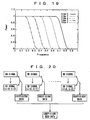
- FIG. 17 shows a concept of the above-mentioned method for producing the coefficient seed data sets.
- a plurality of SD signals is produced from an HD signal.
- SD signals of total 81 kinds are produced with the parameters h and v for varying a horizontal band and a vertical band of a filter used at the time of producing the SD signals from the HD signal being varied respectively at nine steps.
- the coefficient seed data sets are produced.
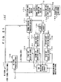
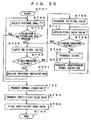
- FIG. 18 shows a configuration of a coefficient seed data production device 150 for producing the coefficient seed data sets based on the above-mentioned concept.
- This coefficient seed data production device 150 includes an input terminal 151 for receiving the HD signal (525p or 1050i signal) as a teacher signal, and an SD signal production circuit 152 for performing a thinning-out processing on this HD signal horizontally and vertically to thereby obtain SD signal as an input signal.
- This SD signal production circuit 152 receives a conversion method selection signal as a control signal. If the first conversion method (for obtaining the 525p signal from the 525i signal at the image signal processing section 110 shown in FIG. 1 ) is selected, the SD signal production circuit 152 performs the thinning-out processing on the 525p signal to thereby produce SD signal (see FIG. 4 ). On the other hand, if the second conversion method (for obtaining the 1050i signal from the 525i signal at the image signal processing section 110 shown in FIG. 1 ) is selected, the SD signal production circuit 152 performs the thinning-out processing on the 1050i signal to thereby produce SD signal (see FIG. 5 ).
- the SD signal production circuit 152 receives the parameters h and v as control signals.
- the horizontal and vertical bands of the filter used when producing the SD signals from the HD signal are varied. The following will describe some examples of details of the filter.
- the filter by a band-pass filter for restricting the horizontal-band frequencies and a band-pass filter for restricting the vertical-band frequencies.
- a band-pass filter for restricting the horizontal-band frequencies
- a band-pass filter for restricting the vertical-band frequencies.
- the filter by a one-dimensional Gaussian filter for restricting the horizontal-band frequencies and a one-dimensional Gaussian filter for restricting the vertical-band frequencies.
- a one-dimensional Gaussian filter for restricting the horizontal-band frequencies
- a one-dimensional Gaussian filter for restricting the vertical-band frequencies.
- the filter by a two-dimensional filter F (h, v) having both horizontal and vertical frequency responses that are decided by the parameters h and v, respectively.
- F (h, v) having both horizontal and vertical frequency responses that are decided by the parameters h and v, respectively.
- this method for producing two-dimensional filter similar to the above-mentioned one-dimensional filter, the two-dimensional frequency response corresponding to the step-wise given values of the parameters h and v is designed, and two-dimensional inverse Fourier transform is performed.
- the two-dimensional filter having the two-dimensional frequency response that corresponds to the step-wise given values of the parameters h and v can be obtained.
- the coefficient seed data production device 150 includes first through third tap selection circuits 153-155 each for selectively extracting, and then transmitting, the plural SD pixel data sets located on a periphery of an objective position in an HD signal (1050i or 525p signal) from the signal (525i signal) received from the SD signal production circuit 152.
- These first through third tap selection circuits 153-155 are constituted like the first through third tap selection circuits 121-123 of the above-mentioned image signal processing section 110.
- a tap to be selected by any of the first through third tap selection circuits 153-155 is specified according to the tap position information received from a tap selection control circuit 156.
- the tap selection control circuit 156 receives a conversion method selection signal as the control signal.
- the first through third tap selection circuits 153-155 are supplied with different tap position information according to a different conversion methods, that is, whether the first conversion method or the second conversion method is selected.
- the tap selection control circuit 156 receives the motion information MV of the motion class from a motion class detection circuit 158, which is described later:
- the tap position information supplied to the second tap selection circuit 154 is adapted to change with the magnitude of the motion.
- the coefficient seed data production device 150 includes a space class detection circuit 157 for detecting a level distribution pattern of the data sets (SD pixel data sets) of the space class tap selectively extracted by the second tap selection circuit 154, for detecting a space class based on this level distribution pattern, and then for transmitting class information of this space class.
- This space class detection circuit 157 is constituted like the space class detection circuit 124 of the above-mentioned image signal processing section 110.
- This space class detection circuit 157 transmits, as class information indicating the space class, a re-quantization code qi for each of the SD pixel data sets as the data sets of the space class tap.
- the coefficient seed data production device 150 includes the motion class detection circuit 158 for detecting a motion class mainly indicating a degree of motion from the data sets (SD pixel data sets) of the motion class tap selectively extracted by the third tap selection circuit 155 and then for transmitting the motion information MV thereof.
- This motion class detection circuit 158 is constituted like the motion class detection circuit 125 of the above-mentioned image signal processing section 110.
- This motion class detection circuit 158 calculates inter-frame differences from the data sets (SD pixel data sets) of the motion class tap selectively extracted by the third tap selection circuit 155 to then perform threshold value processing on an average value of the absolute values of these differences, thus detecting a motion class that provides an index of motion.
- the coefficient seed data production device 150 includes a class synthesis circuit 159 for obtaining a class code CL for indicating a class including pixel data set of an objective position in the HD signal (525p or 1050i signal), based on the re-quantization code qi given as class information of the space class received from the space class detection circuit 157 and the motion information. MV of the motion class received from the motion class detection circuit 158.
- This class synthesis circuit 159 is also constituted like the class synthesis circuit 126 of the above-mentioned image signal processing section 110.
- the coefficient seed data production device 150 includes a normal equation production section 160 for producing a normal equation (see the Equation (13)) to be used for obtaining the coefficient seed data sets w 10 through w n9 for each class, based on each of the HD pixel data sets y given as pixel data set of the objective position obtained from the HD signal received at the input terminal 151, data sets (SD pixel data sets) xi of the prediction tap selectively extracted by the first tap selection circuit 153 respectively in correspondence with thus obtained each of the HD pixel data sets y, and the class code CL received from the class synthesis circuit 159 respectively in correspondence with each of the HD pixel data sets y thus obtained.
- a normal equation production section 160 for producing a normal equation (see the Equation (13)) to be used for obtaining the coefficient seed data sets w 10 through w n9 for each class, based on each of the HD pixel data sets y given as pixel data set of the objective position obtained from the HD signal received at the input terminal 151, data sets (SD pixel data
- learning data sets are produced in combination of one of the HD pixel data sets y and the pixel data sets of the prediction tap in number of n each corresponding thereto.
- the parameters h and v to be supplied to the SD signal production circuit 152 are sequentially changed so that a plurality of SD signals having the horizontal and vertical bands each varying in a step-by-step manner can be sequentially produced.
- a normal equation having many learning data sets registered therein is produced in the normal equation production section 160.
- the coefficient seed data sets calculated by learning between the HD signal and the SD signals produced by passing this HD signal through a narrow-band filter are used to obtain the HD signal with a high resolution.
- the coefficient seed data sets calculated by learning between the HD signal and the SD signals produced by passing this HD signal through a wide-band filter are used to obtain the HD signal with a low resolution.
- a plurality of SD signals can be produced sequentially to thereby register the learning data sets, thus obtaining the coefficient seed data sets for obtaining HD signal having continuous resolution.
- the coefficient seed data production device 150 includes a coefficient seed data decision section 161 for receiving data sets of the normal equation produced for each class by the normal equation production section 160, and for solving this class-specific normal equation in order to obtain coefficient seed data sets w 10 through w n9 for each class, and a coefficient seed memory 162 for storing thus obtained coefficient seed data sets w 10 through w n9 .
- the coefficient seed data decision section 161 solves the normal equation according to a method such as the sweeping-out method, thus obtaining coefficient seed data sets w 10 through w n9 .
- HD signal (525p or 1050i signal) as a teacher signal is supplied to the input terminal 151 and then it undergoes thinning-out processing both horizontally and vertically in the SD signal production circuit 152, thus producing SD signal (525i signal) as an input signal.
- the SD signal production circuit 152 performs the thinning-out processing on the 525p signal to thereby produce the SD signal.
- the SD signal production circuit 152 receives the parameters h and v as the control signals to sequentially produce a plurality of the SD signals having horizontal and vertical bands each varying in a step-by-step manner.
- the second tap selection circuit 154 Based on these SD signals (525i signals), the second tap selection circuit 154 selectively extracts the data sets (SD pixel data sets) of the space class tap located on a periphery of an objective position in the HD signal (525p or 1050i signal). This second tap selection circuit 154 selects a tap based on the tap position information, which is supplied from the tap selection control circuit 156, corresponding to selected conversion method and a motion class detected by the motion class detection circuit 158.
- the data sets (SD pixel data sets) of the space class tap selectively extracted by this second tap selection circuit 154 are supplied to the space class detection circuit 157.
- This space class detection circuit 157 performs ADRC processing on each of the SD pixel data sets given as the data sets of the space class tap to thereby obtain the re-quantization code qi used as the class information of the space class (class grouping mainly for indicating of a waveform in a space) (see the Equation (1)).
- the third tap selection circuit 155 selectively extracts the data sets (SD pixel data sets) of a motion class tap located on a periphery of the objective position in the HD signal. In this case, the third tap selection circuit 155 selects a tap based on the tap position information, which is supplied from the tap selection control circuit 156, corresponding to a selected conversion method.
- the data sets (SD pixel data sets) of a motion class tap selectively extracted by this third tap selection circuit 155 are supplied to the motion class detection circuit 158.
- This motion class detection circuit 158 obtains motion information MV of a motion class (class grouping for mainly indicating a degree of motion) based on each of the SD pixel data sets given as the data sets of the motion class tap.
- This motion information MV and the above-mentioned re-quantization code qi are supplied to the class synthesis circuit 159.
- This class synthesis circuit 159 obtains a class code CL indicating a class that includes the pixel data set of the objective position in the HD signal (525p or 1050i signal), based on this motion information MV and the re-quantization code qi (see the Equation (3)).
- the first tap selection circuit 153 selectively extracts the data sets (SD pixel data sets) of the prediction tap located on a periphery of the objective position in the HD signal. In this case, the first tap selection circuit 153 selects a tap based on the tap position information, which is supplied from the tap selection control circuit 156, corresponding to a selected conversion method.
- the normal equation production circuit 160 produces a normal equation for producing coefficient seed data sets w 10 through w n9 (see the Equation (13)) for each class based on each of the HD pixel data sets y given as pixel data set of the objective position obtained from the HD signal supplied at the input terminal 151, the data sets (SD pixel data sets) xi of the prediction tap selectively extracted by the first tap selection circuit 153 in respective correspondence to each of the HD pixel data sets y thus given, and a class code CL received from the class synthesis circuit 159 in respective correspondence to each of the HD pixel data sets y thus given.
- coefficient seed data decision section 161 which obtains coefficient seed data sets w 10 through w n9 for each class.
- coefficient seed data sets w 10 through w n9 are stored in the coefficient seed memory 162 in which the addresses are sub-divided for each class.
- the coefficient seed data production device 150 shown in FIG. 18 can produce class-specific coefficient seed data sets w 10 through w n9 to be stored in the information memory bank 135 of the image signal processing section 110 shown in FIG. 1 .
- the SD signal production circuit 152 produces the SD signal (525i signal) using the 525p or 1050i signal according to selected conversion method, thus producing the coefficient seed data sets each corresponding to the first conversion method (for obtaining the 525p signal from the 525i signal at the image signal processing section 110) and the second conversion method (for obtaining the 1050i signal from the 525i signal at the image signal processing section 110).
- FIG. 20 shows a concept of this example. Based on this concept, a plurality of SD signals is produced from an HD signal. For example, SD signals of total 81 kinds are produced with varying in nine steps the parameters h and v, respectively, for varying the horizontal and vertical bands of a filter used in production of the SD signals from the HD signal. Then learning is performed between each of the SD signals thus produced and the HD signal so that the coefficient data sets Wi to be used in the estimation equation of the Equation (4) can be produced. Then, the coefficient seed data sets are produced using the coefficient data sets Wi thus produced corresponding to each of the SD signals.
- Equation (15) term m indicates the number of learning data sets and term n indicates the number of prediction taps.
- Equation (16) conditions in the number of n based on the value i in the Equation (18) are considered, and W 1 , W 2 , ..., W n having values satisfying these conditions may be calculated.
- Equation (19) following Equation (19) can be obtained.
- Equation (20) following Equation (20) can be obtained.
- Equation (21) a normal equation of following Equation (21) can be obtained.
- Equation (21) Since the normal equation of the Equation (21) is capable of making equations in the same number as unknown number n, the most probable value of each Wi can be obtained. In this case, the simultaneous equations are solved using the sweeping-out method etc.
- coefficient data sets in a certain class which are obtained as a result of learning performed by use of the SD signals, corresponding to the parameters h and v, to be k vhi .
- the term i indicates a prediction tap number. From this value of k vhi , coefficient seed data sets of this class are obtained.
- Equation (22) the residual is given by following Equation (22).
- Equation (23) is changed to following Equation (26).
- X jk ⁇ v ⁇ h t j ⁇ t k
- Y j ⁇ v ⁇ h t j ⁇ k vhi X 00 X 01 ⁇ X 09
- X 10 X 11 ⁇ X 19 ⁇ ⁇ ⁇ ⁇ X 90
- X 91 ⁇ X 99 ⁇ w i ⁇ 0 w i ⁇ 1 ⁇ w i ⁇ 9 Y 0 Y 1 ⁇ Y 9
- This Equation (26) is also a normal equation and so can be solved by a general solution such as the sweeping-out method, thus calculating the coefficient seed data sets w 10 through w n9 .
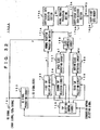
- FIG. 21 shows a configuration of another coefficient seed data production device 150' for producing coefficient seed data sets based on a concept shown in FIG. 20 .
- components that correspond to those in FIG. 20 are indicated by the same reference symbols and their detailed description is omitted.
- a normal equation see the Equation (21)
- learning data sets are produced in combination of one of the HD pixel data sets y and the pixel data sets of the prediction tap in the number of n corresponding thereto.
- the parameters h and v to be supplied to the SD signal production circuit 152 are sequentially changed so that a plurality of SD signals which have horizontal and vertical bands changed step-wise can be sequentially produced, thus producing learning data sets between the HD signal and each of the SD signals.
- This permits the normal equation production section 171 to produce a normal equation for obtaining the coefficient data sets Wi (i 1 to n) for each class in respective correspondence with each of the SD signals.
- the coefficient seed data production device 150' includes a coefficient data decision section 172 for receiving data sets of the normal equation produced by the normal equation production section 171 to then solve this normal equation in order to obtain the coefficient data sets Wi for each class in respective correspondence to each SD signal, and a normal equation production section 173 for producing a normal equation (see the Equation (26)) for obtaining the coefficient seed data sets w 10 through w n9 for each class using the class-specific coefficient data sets Wi that correspond to each of the SD signals.
- the coefficient seed data production device 150' includes a coefficient seed data decision section 174 for receiving data sets of the normal equation produced for each class by the normal equation production section 173 to then solve the normal equation for each class in order to obtain the coefficient seed data sets w 10 through w n9 for each class, and the coefficient seed memory 162 for storing coefficient seed data sets w 10 through w n9 thus obtained.
- the other components of the coefficient seed data production device 150' shown in FIG. 21 are constituted like those of the coefficient seed data production device 150 shown in FIG. 18 .
- an HD signal (525p or 1050i signal) as a teacher signal is supplies. Then, the HD signal is subjected to the thinning-out processing horizontally and vertically in the SD signal production circuit 152, thus producing the SD signal (525i, signal) as the input signal.
- the SD signal production circuit 152 performs a thinning-out processing on the 525p signal to produce the SD signal.
- the second conversion method for obtaining the 1050i signal from the 325i signal by the image signal processing section 110 shown in FIG. 1
- the SD signal production circuit 152 performs a thinning-out processing on the 1050i signal to produce the SD signal.
- the SD signal production circuit 152 receives the parameters h and v as the control signal so that a plurality of SD signals are sequentially produced with their horizontal and vertical bands varying in a step-by step manner.
- the second tap selection circuit 154 Based on the SD signals (525i signals), the second tap selection circuit 154 selectively extracts the data sets (SD pixel data sets) of a space class tap located on a periphery of an objective position in the HD signal (525p or 1050i signal). This second tap selection circuit 154 selects a tap based on the tap position information, which is received from the tap selection control circuit 156, corresponding to a selected conversion method and a motion class detected by the motion class detection circuit 158.
- the data sets (SD pixel data sets) of the space class tap selectively extracted by this second tap selection circuit 154 are supplied to the space class detection circuit 157.
- This space class detection circuit 157 performs ADRC processing on each of the SD pixel data sets given as the data sets of the space class tap to thereby obtain a re-quantization code qui used as class information of a space class (class grouping mainly for indicating of a waveform in a space) (see the Equation (1)).
- the third tap selection circuit 155 selectively extracts the data sets (SD pixel data sets) of a motion class tap located on a periphery of the objective position in the HD signal. In this case, the third tap selection circuit 155 selects a tap based on the tap position information, which is supplied from the tap selection control circuit 156, corresponding to the selected conversion method.
- the data sets (SD pixel data sets) of the motion class tap selectively extracted by this third tap selection circuit 155 are supplied to the motion class detection circuit 158.
- This motion class detection circuit 158 obtains motion information MV of a motion class (class grouping for mainly indicating a degree of motion) based on each of the SD pixel data sets given as data sets of the motion class tap.
- the motion information MV and the above-mentioned re-quantization code qi are supplied to the class synthesis circuit 159.
- This class synthesis circuit 159 obtains a class code CL that indicates a class including pixel data set of an objective position in the HD signal (525p or 1050i signal), based on this motion information MV and the re-quantization code qi (see the Equation (3)).
- the first tap selection circuit 153 selectively extracts the data sets (SD pixel data sets) of a prediction tap located on a periphery of the objective position in the HD signal. In this case, the first tap selection circuit 153 selects a tap based on the tap position information, which is supplied from the tap selection control circuit 156, corresponding to the selected conversion method.
- this normal equation is solved by the coefficient data decision section 172 so that coefficient data sets Wi for each class in respective correspondence to each of the SD signals can be obtained.
- the normal equation production section 173 Based on the class-specific coefficient data sets Wi corresponding to each of the SD signals, the normal equation production section 173 produces a normal equation (see the Equation (26)) for obtaining coefficient seed data sets w 10 through w n9 for each class.
- this normal equation is solves by the coefficient seed data decision section 174 so that the coefficient seed data sets w 10 through w n9 for each class can be obtained.
- the coefficient seed data sets w 10 through w n9 are stored in the coefficient seed memory 162 in which the addresses are sub-divided for each class.
- the coefficient seed data production device 150' shown in FIG. 21 can also produce coefficient seed data sets w 10 through w n9 for each class which are to be stored in the information memory bank 135 of the image signal processing section 110 shown in FIG. 1 .
- the SD signal production circuit 152 can produce the SD signal (525i signal) using the 525p or 1050i signal based on a selected conversion method, and it can also specifically produce coefficient seed data sets that correspond to any one of the first conversion method (for obtaining the 525p signal from the 525i signal at the image signal processing section 110) and the second conversion method (for obtaining the 1050i signal from the 525i signal at the image signal processing section 110).
- W 1 w 10 + w 11 ⁇ v + w 12 ⁇ h + w 13 ⁇ v 2 + w 14 ⁇ h 2 + w 15 ⁇ v 3 + w 16 ⁇ h 3
- W 2 w 20 + w 21 ⁇ v + w 22 ⁇ h + w 23 ⁇ v 2 + w 24 ⁇ h 2 + w 25 ⁇ v 3 + w 26 ⁇ h 3
- W i w i ⁇ 0 + w i ⁇ 1 ⁇ v + w i ⁇ 2 ⁇ h + w i ⁇ 3 ⁇ v 2 + w i ⁇ 4 ⁇ h 2 + w i ⁇ 5 ⁇ v 3 + w i ⁇ 6 ⁇ h 3
- W n w n ⁇ 0 + w n ⁇ 1 ⁇ v + w n ⁇ 2 ⁇ h + w n ⁇ 3 ⁇ W
- the image signal processing section 110 of FIG. 1 can set the parameters h and v which specify horizontal and vertical resolutions respectively to then adjust the values of these parameters for adjustment of the horizontal and vertical resolutions of an image
- the invention is not limited thereto; for example, a Parameter z which specifies a degree of noise cancellation (degree of noise reduction) may be provided so that its value can be adjusted to adjust the noise cancellation degree in the image.
- W 1 w 10 + w 11 ⁇ z + w 12 ⁇ z 2 + w 13 ⁇ z 3
- W 2 w 20 + w 21 ⁇ z + w 22 ⁇ z 2 + w 23 ⁇ z 3
- W i w i ⁇ 0 + w i ⁇ 1 ⁇ z + w i ⁇ 2 ⁇ z 2 + w i ⁇ 3 ⁇ z 3
- W n w n ⁇ 0 + w n ⁇ 1 ⁇ z + w n ⁇ 2 ⁇ z 2 + w n ⁇ 3 ⁇ z 3
- W 1 w 10 + w 11 ⁇ z + w 12 ⁇ z 2
- W 2 w 20 + w 21 ⁇ z + w 22 ⁇ z 2 ⁇
- W i w i ⁇ 0 + w i ⁇ 1 ⁇ z + w i ⁇ 2 ⁇ z 2
- the coefficient seed data sets which are coefficient data sets in the production equation containing the parameter z as mentioned above, can be produced by the coefficient seed data production device 150 shown in FIG. 18 or the coefficient seed data production device 150' shown in FIG. 21 like in a case of producing the coefficient seed data sets, which are coefficient data sets in the production equation containing the above-mentioned parameters h and v.
- the SD signal production circuit 152 receives the parameter z as a control signal, so that a noise adding state into the SD signal is changed step-wise corresponding to a value of this parameter z when the SD signals are produced from the HD signal.
- the coefficient seed data sets can be produced for obtaining continuous noise cancellation degrees.
- the SD signals are produced with their noise level varying step-wise.
- a screen region to be added varies step-wise.
- noise i For example, for "noise 0”, learning is performed 100 times on each of the SD signals containing no noise, while for “noise i”, learning is performed 30 times on each of the SD signals containing no noise and 70 times on each of the SD signals containing noise. Therefore, "noise i" provides a learning system of calculating the coefficient seed data sets with a higher noise cancellation. By thus varying step-wise the number of times of learning performed on the SD signals containing no noise and that containing noise, coefficient seed data sets for obtaining continuous noise cancellation degrees can be obtained.
- this method can be also implemented in a form of addition of normal equations.
- Equation (21) is used as the normal equation employed in this calculation. Defining P ij and Q j to be such as given in following Equations (31) and (32), respectively, the Equation (21) can be changed into following Equation (33).
- x ij indicates the i-th learned value of the SD pixel data sets of the j-th prediction tap position
- y i indicates the i-th learned value of HD pixel data sets
- Wi indicates a coefficient
- the left-band side member and the right-hand side member of the Equation (33) are defined to be [P1 ij ] and [Q1 i ] respectively in a case where the SD signal containing no noise is learned, while likewise the left-hand member and the righthand side member of the Equation (33) are defined to be [P2 ij ] and [Q2 ⁇ ] respectively in a case where the SD signal containing noise is learned.
- [P aij ] and [Q ai ] are defined like in following Equations (34) and (35).
- the term "a" satisfies a relationship of 0 ⁇ a ⁇ 1.
- P aij 1 - a ⁇ P ⁇ 1 ij + a P ⁇ 2 ij
- Q ai 1 - a ⁇ Q ⁇ 1 i + a Q ⁇ 2 i
- P aij ⁇ W i Q ai
- target coefficient seed data sets can be obtained.
- the normal equation for each noise level is used to calculate coefficient data sets Wi, which is in turn used to obtain coefficient seed data sets.
- Equations (24) and (25) are changed to following Equations (38) and (39), respectively.
- Equation (40) By solving following Equation (40) with respect to these equations, the coefficient seed data sets w ij can be obtained.
- a variable indicating a total sum of prediction taps is changed to m.
- the image signal processing section 11-0 of FIG. 1 sets the parameters h and v for specifying the horizontal and vertical resolutions respectively and adjusts their values to thereby adjust the horizontal and vertical resolutions of an image
- the invention is not limited thereto; for example, both the horizontal and vertical resolutions may be adapted to be adjusted by one parameter in configuration.
- one parameter r may be set to specify the horizontal and vertical resolutions.
- the image signal processing section 110 of FIG. 1 sets the parameters h and v for specifying the horizontal and vertical resolutions respectively and adjusts their values to thereby adjust the horizontal and vertical resolutions of an image
- the invention is not limited thereto; for example, the parameter r for adjusting these horizontal and vertical resolutions and the above-mentioned parameter z for specifying the above-mentioned noise cancellation degree (noise reduction degree) may be set to adjust the values of these parameters r and z, thus adjusting the horizontal and vertical resolutions of an image and the noise cancellation degree in a similar configuration.
- Equation (41) w 10 + w 11 ⁇ r + w 12 ⁇ z + w 13 ⁇ r 2 + w 14 ⁇ rz + w 15 ⁇ z 2 + w 16 ⁇ r 3 + w 17 ⁇ r 2 ⁇ z + w 18 ⁇ rz 2 + w 19 ⁇ z 3
- a user interface for adjusting the parameters r and z can be also constituted as shown in FIG. 2 .
- the user can operate the joystick 200a to thereby move the position of the icon 115a on the adjustment screen 115, thus arbitrarily adjusting the values of the parameters r and z which specify the resolution and the noise cancellation degree (noise reduction degree), respectively.
- FIG. 24 shows an expanded part of the adjustment screen 115.
- the user can easily adjust the parameters r and z with referencing the adjustment screen 115 displayed on the display section 111 (see FIG. 2 ). Note here that the values of the parameters r and z adjusted by the user may be digitally indicated on the adjustment screen 115.
- the coefficient seed data sets which are coefficient data sets in the production equation containing the parameters r and z, can be produced by the coefficient seed data production device 150 shown in FIG. 18 or the coefficient seed data production device 150' shown in FIG. 21 like in a case of producing the coefficient seed data sets, which are coefficient data sets in the production equation containing the above-mentioned parameters h and v.
- the SD signal production circuit 152 receives parameters r and z as the control signals, so that when the SD signals are produced from the HD signal, the horizontal and vertical bands of each of the SD signals and the state of adding noise into the SD signals vary step-wise corresponding to the values of these parameters r and z.
- FIG. 23 shows an example of producing the SD signals each corresponding to the values of the parameters r and z.
- the parameters r and z vary in nine steps, respectively, to produce SD signals of total 81 kinds.
- the parameters r and z may vary in 10 steps or more. In this case, the accuracy is improved for calculating the coefficient seed data sets but the amount of calculations to be performed is increased.
- the image signal processing section 110 of FIG. 1 sets the parameters h and v which specify the horizontal and vertical resolutions respectively and adjusts their values to adjust the horizontal and vertical resolutions of an image
- the invention is not limited thereto; for example, the above-mentioned parameters z for specifying the noise cancellation degree (noise reduction degree) may similarly be set, besides these parameters h and v so that the values of these parameters h, v, and z can be adjusted, thereby adjusting the horizontal and vertical resolutions and the noise cancellation degree in configuration.
- Equation (42) w 1 _ 0 + w 1 _ 1 ⁇ v + w 1 _ 2 ⁇ h + w 1 _ 3 ⁇ z + w 1 _ 4 ⁇ v 2 + w 1 _ 5 ⁇ h 2 + w 1 _ 6 ⁇ z 2 + w 1 _ 7 ⁇ vh + w 1 _ 8 ⁇ hz + w 1 _ 9 ⁇ zv + w 1 _ 10 ⁇ v 3 + w 1 _ 11 ⁇ h 3 + w 1 _ 12 ⁇ z 3 + w 1 _ 13 ⁇ v 2 ⁇ h + w 1 _ 14 ⁇ vh 2 + w 1 _ 15 ⁇ vhz +
- a user interface for adjusting the parameters h, v, and z can also be constituted as shown in FIG. 2 .
- the user can operate the joystick 200a to move the position of the icon 115a on the adjustment screen 115, thus arbitrarily adjusting the values of the parameters h and v which specify the resolutions and of the parameter z that specifies the noise cancellation degree (noise reduction degree).
- FIG. 26 shows an expanded part of the adjustment screen 115.
- the value of the parameter h for deciding the horizontal resolution can be adjusted; when it is moved up and down, the value of the parameter v for deciding the vertical resolution can be adjusted; and when the icon 115a is moved in the depth direction, the parameter z for adjusting the noise cancellation degree can be adjusted.
- the joystick 200a can be obliquely operated.
- the depth direction can be expressed by changing the size, the color thickness or hue, etc. of the icon 115a.
- the icon 115a indicated by a broken line is changed in size to indicate that the icon 115a itself indicated by a solid line in the figure has moved-in the depth direction.
- the user can easily adjust the parameters h, v, and z with referencing the adjustment screen 115 displayed on the display section 111 (see FIG. 2 ).
- the values of the parameters h, v, and z adjusted by the user may be digitally indicated on the adjustment screen 115.
- the coefficient seed data sets which are coefficient data sets in the production equation containing the parameters h, v, and z, can be produced by the coefficient seed data production device 150 shown in FIG. 18 or the coefficient seed data production device 150' shown in FIG. 21 like in a case of producing coefficient seed data sets, which are coefficient data sets in the production equation containing the above-mentioned parameters h and v.
- the SD signal production circuit 152 receives the parameters h, v, and z as the control signals, so that when the SD signals are produced from the HD signal, the horizontal and vertical bands of each of the SD signals and the state of adding noise into the SD signals vary step-wise corresponding to the values of these parameters h, v, and z.
- FIG. 25 shows an example of producing the SD signals each corresponding to the values of the parameters h, v, and z.
- the parameters h, v, and z vary in nine steps, respectively, to produce SD signals of total 729 kinds.
- the parameters h, v, and z may vary in 10 steps or more. In this case, the accuracy is improved for calculating the coefficient seed data sets but the amount of calculations to be performed is increased.
- the processing performed at the image signal processing section 110 of FIG. 1 may be carried out software-wise by, for example, an image signal processor 300 shown in FIG. 27 .
- This image signal processor 300 comprises a CPU 301 for controlling the operations of the apparatus as a whole, a ROM (Read Only Memory) 302 for storing operation programs of this CPU 301, coefficient seed data sets, etc., and a RAM (Random Access Memory) 303 constituting a work area for the CPU301.
- ROM Read Only Memory
- RAM Random Access Memory
- the image signal processor 300 comprises a hard disk drive (HDD) 305 and a flexible disk (herein after called floppy disk) drive (FDD) 307 for driving a floppy disk 306, which are used as an external memory.
- HDD hard disk drive
- FDD flexible disk drive
- the image signal processor 300 comprises a communication section 308 for connecting to a communication network 400 such as the Internet through either wired transmission or wireless transmission.
- This communication section 308 is connected to the bus 304 via an interface 309.
- the image signal processor 300 comprise a user interface section.
- This user interface section has a remote control signal receiving circuit 310 for receiving a remote control signal RM from a remote control transmitter 200, and a display 311 consisting of an Liquid Crystal Display (LCD) and the like.
- the remote control signal receiving circuit 310 is connected via an interface 312 to the bus 304 and, similarly, the display 311 is connected via an interface 313 to the bus 304.
- the image signal processor 300 comprises an input terminal 314 for receiving the SD signal, and an output terminal 315 for transmitting the HD signal.
- the input terminal 314 is connected via an interface 316 to the bus 304 and, similarly, the output terminal 315 is connected via an interface 317 to the bus 304.
- the coefficient seed data sets, etc. may be downloaded via the communication section 308 from the communication network 400 such as the Internet, and accumulated on the hard disk or in the RAM 303 for use. Also, these processing programs, the coefficient seed data sets, etc. may be provided on the floppy disk 306.
- the SD signal may be recorded on the hard disk beforehand or downloaded via the communication section. 308 from the communication network 400 such as the Internet.
- the SD signal instead of transmitting processed HD signal through the output terminal 315 or concurrent with this, an image of the processed HD signal may be supplied to the display 311 to be displayed thereon, the processed HD signal may be stored on the hard disk or it may be sent via the communication section 308 to the communication network 400 such as the internet.
- step ST1 the processing starts at step ST1 and, at step ST2, SD pixel data sets are input in units of a frame or a field. If the SD pixel data sets are input through the input terminal 314, then the RAM 303 temporarily stores the SD pixel data sets. Also, if the SD pixel sets are recorded on a hard disk, then the SD pixel data sets are read out of the hard disk drive 305 and the RAM 303 temporarily stores them.
- step ST3 it is judged whether or not the processing of the input SD pixel data sets in all the frames or fields is finished. If it is finished, then the process finishes at step ST4. Contrarily, if it is not finished, then the procedure goes to step ST5.
- a picture quality specification value for example, a value of the parameter h or v
- the coefficient data sets Wi to be used in the estimation equation (see the Equation (4)) for each class are produced according to a production equation (see the Equation (5)) using thus read picture quality specification value and the coefficient seed data sets for each class.
- step ST7 based on the SD pixel data sets input at step ST2, pixel data sets of class taps and prediction taps corresponding to each HD pixel data set to be produced are obtained.
- step ST8 it is judged whether or not the processing of obtaining the HD pixel data sets in all the regions of the input SD pixel data sets is finished. If it is finished, then the procedure returns to step ST2, thus shifting to the processing of inputting SD pixel data set of the next frame or field. On the other hand, if it is not finished, then the procedure goes to step ST9.
- a class code CL is produced from the SD pixel data sets of the class taps obtained at step ST7.
- the HD pixel data sets are produced according to the estimation equation using the coefficient data sets corresponding to that class code CL and the SD pixel data sets of the prediction taps, and then the procedure returns to step ST7 wherein the above-mentioned processing is repeated.
- the processing along the flowchart shown in FIG. 28 is performed to process the SD pixel data sets that constitute the input SD signal, so that HD pixel data sets that constitute the HD signal sets can be obtained.
- the HD signal thus processed and obtained is transmitted through the output terminal 315 or supplied to the display 311 that displays an image thereon or even supplied to the hard disk drive 305 that records them on a hard disk.
- processing at the coefficient seed data production device 150 of FIG. 18 can be carried out software-wise by a processing apparatus, not shown.
- the procedure starts at step ST21 and, at step ST22, a picture quality pattern (which is identified by, for example, the parameters h and v) to be used in learning is selected.
- step ST23 it is judged whether or not the learning on all the picture quality patterns is finished. If learning on all of them is not finished, the procedure goes to step ST24.
- step ST24 already known HD pixel data sets are input in units of a frame or field.
- step ST25 it is judged whether or not the processing on all the HD pixel data sets is finished. If it is finished, then the procedure returns to step ST22 wherein the next picture quality pattern is selected and then the above-mentioned processing is repeated. If it is not finished yet, the procedure goes to step ST26.
- step ST26 SD pixel data sets are produced from the HD pixel data sets input at step ST24 on the basis of the picture, quality pattern selected at ST22.
- step ST27 pixel data sets of class taps and prediction taps are obtained in correspondence to each HD pixel data set input at the step ST24 on the basis of the SD pixel data sets produced at step ST26.
- step ST28 it is judged whether or not the learning processing on all the regions of the produced SD pixel data sets is finished. If it is finished, then the procedure returns to step ST24 wherein the above-mentioned processing is repeated after the next HD pixel data sets are input, while it is not finished yet, then the procedure goes to step ST29.
- a class code CL is produced from the SD pixel data sets of the class taps obtained at step ST27.
- a normal equation (see the Equation (13)) is produced. Then, the procedure returns to step S27.
- step ST31 the normal equation is solved according to the sweeping method etc. to calculate the coefficient seed data sets for each class and, at step ST32, the coefficient seed data sets are stored in a memory and then, at step ST33, the processing ends.
- the processing is performed along the flowchart shown in FIG. 29 so that the coefficient seed data sets for each class can be obtained using the same method as that by the coefficient seed data production device 150 shown in FIG. 18 .
- processing by the coefficient seed data production device 150' of FIG. 21 can also be carried out software-wise by a processing apparatus, not shown.
- the procedure starts at step ST41 and, at step ST42, a picture quality pattern (which is identified by, for example, the parameters h and v) to be used in learning is selected.
- step ST43 it is judged whether the processing for calculating all the picture quality patterns is finished. If it is not finished, the procedure goes to step ST44.
- step ST44 already known HD pixel data sets are input in units of a frame or field.
- step ST45 it is judged whether the processing on all the HD pixel data sets is finished. If it is not finished, the procedure goes to step ST46 wherein the SD pixel data sets are produced from the HD pixel data sets input at step ST44 on the basis of the picture quality pattern selected at step ST42.
- step ST47 pixel data sets of the class taps and the prediction taps corresponding to each HD pixel data set input at step ST44 are obtained from the SD pixel data sets produced at step ST46.
- step ST48 it is judged whether the learning processing on all the regions of the produced SD pixel data sets is finished. If it is finished, the procedure returns to step ST44 wherein the above-mentioned processing is repeated after the next HD pixel data sets are input, while it is not finished yet, the procedure goes to step ST49.
- a class code CL is produced from the SD pixel data sets of the class tap obtained at step ST47.
- a normal equation (see the Equation (21)) for obtaining coefficient data sets is produced. Then, the procedure returns to step ST47.
- step ST45 the procedure goes to step ST51 wherein the normal equation produced at step ST50 is solved using the sweeping method etc. in order to calculate the coefficient data sets for each class. Then, the procedure returns to step S42 wherein the next picture quality pattern is selected, and then the above described processing is repeated to obtain the coefficient data sets for each class that correspond to this next picture quality pattern.
- step ST43 if it decides at step ST43 that the coefficient data sets for all the picture quality patterns are calculated, the procedure goes to step ST52.
- step ST52 a normal equation (see the Equation (26)) for obtaining the coefficient seed data sets is produced from the coefficient data sets on all the picture quality patterns.
- step ST53 the normal equation produced at step ST52 is solved using the sweeping method etc., to calculate the coefficient seed data sets for each class and, at step ST54, the coefficient seed data sets are stored in the memory and then, at step ST55, the processing ends.
- the processing is performed along the flowchart shown in FIG. 30 , so that the coefficient seed data sets for each class can be obtained using the same method as that by the coefficient seed data production device 150' shown in FIG. 21 .
- FIG. 31 shows a configuration of a TV receiver 100A according to another embodiment.
- This TV receiver 100A receives a 525i signal as an SD signal from a broadcast signal to then convert this 525i signal into a 525p or 1050i signal as an HD signal, thus displaying an image based on this 525p or 1050i signal.
- the corresponding components are indicated by the same reference symbols.
- the TV receiver 100A is the same as the TV receiver 100 shown in FIG. 1 except that the image signal processing section 110 is replaced by an image signal processing section 110A.
- the TV receiver 100A performs almost the same operations as the TV receiver 100 does.
- the detailed image signal processing section 110A will be described as follows.
- the components corresponding to the ones of the image signal processing section 110 shown in FIG. 1 are indicated by the same reference symbols and their detailed explanation is omitted.
- the image signal processing section 110A includes an information memory bank 135A.
- the information memory bank 135A accumulates therein beforehand operation specification information to be stored in the register 130 and tap position information to be stored in the registers 131-133 like the information memory bank 135 in the image signal processing section 110 shown in FIG. 1 . Further, this information memory bank 135A accumulates therein beforehand coefficient seed data sets that correspond to the first conversion method (325p) and the second conversion method (1050i), respectively.
- the coefficient seed data sets are coefficient data sets in a production equation for producing coefficient data sets to be stored in the coefficient memory 134.
- the estimation/prediction calculation circuit 127 calculates HD pixel data sets y to be produced, according to the estimation equation of the Equation (4) based on the data sets (SD pixel data sets) xi of the prediction tap and the coefficient data sets Wi read out of the coefficient memory 134.
- W i w i ⁇ 0 + w i ⁇ 1 ⁇ c + w i ⁇ 2 ⁇ c 2 + w i ⁇ 3 ⁇ c 3
- This parameter c corresponds to a class code CL transmitted from the class synthesis circuit 126.
- the information memory bank 135A stores therein for each conversion method the coefficient seed data sets w i0 through w i3 , which are coefficient data sets in this production equation. How to produce the coefficient seed data sets will be described later.
- the system controller 101 supplies a parameter P to the space class detection circuit 124 and the class synthesis circuit 126.
- This parameter P indicates the number of re-quantization bits.
- the class synthesis circuit 126 calculates a re-quantization code qi used as class information of the space class in the calculation of the above-mentioned Equation (1) and the class synthesis circuit 126 obtains the class code CL in the calculation of the Equation (3), wherein a value of the parameter P is used as the number of re-quantization bits in the Equations (1) and (3).
- the value of this parameter P can be changed by the user's operations; for example, the value of P can be 1, 2, or 3.
- the value of the class code CL obtained by calculations is divided by (2 P-1 ) 6 when the Equation (3) is calculated by the class synthesis circuit 126 so that the class code CL can be unchanged in range even if the value of the parameter P is changed.
- the coefficient production circuit 136A receives a value of the parameter P from the system controller 101.
- the coefficient data sets Wi for each class are specifically produced by the coefficient production circuit 136A in, for example, each vertical blanking period.
- the image signal processing section 114A has the same configuration as the image signal processing section 110 of FIG. 1 except for the above.
- the second tap selection circuit 122 Based on the SD signal (525i signal) stored in the buffer memory 109, the second tap selection circuit 122 selectively extracts data sets (SD pixel data sets) of a space class tap. In this case, the second tap selection circuit 122 selects a tap based on tap position information, which is supplied from the register 132, corresponding to a user-selected conversion method and a motion class detected by the motion class detection circuit 125.
- Data sets (SD pixel-data sets) of the space class tap extracted selectively by the second tap selection circuit 122 are supplied to the space class detection circuit 124.
- This space class detection circuit 124 performs ADRC processing on each of the SD pixel data sets given as the data sets of the space class tap to obtain the re-quantization code qi as class information of the space class (class, grouping mainly for indicating of a waveform in the space)(see the Equation (1)).
- the third tap selection circuit 123 selectively extracts data sets (SD pixel data sets) of a motion class tap. In this case, the third tap selection circuit 123 selects a tap based on tap position information, which is supplied from the register 133, corresponding to a user-selected conversion method.
- the data sets (SD pixel data sets) of the motion class tap extracted selectively by the third tap selection circuit 123 are supplied to the motion class detection circuit 125.
- This motion class detection circuit 125 obtains motion information MV of a motion class (class grouping mainly for indicating a degree of motion) from each of the SD pixel data sets given as data sets of the motion class tap.
- This motion information MV and the above-mentioned re-quantization code qi are supplied to the class synthesis circuit 126.
- This class synthesis circuit 126 in turn obtains a class code CL that indicates a class including pixel data set (pixel data set of an objective position) of the HD signal (525p or 1050i signal) to be produced based on this motion information MV and the re-quantization code qi (see the Equation (3)).
- This class code CL is then supplied as read-out address information to the coefficient memory 134 and the normalization coefficient memory 138.
- the coefficient memory 134 receives the class code CL as read-out address information, so that the coefficient data sets Wi corresponding to the class code CL are read out of this coefficient memory 134 and the coefficient data sets Wi are supplied to the estimation/prediction calculation circuit 127. Also, based on the SD signal (525i signal) stored in the buffer memory 109, the first tap selection circuit 121 selectively extracts the data sets (SD pixel data sets) of the prediction tap. In this case, the first tap selection circuit 121 selects a tap based on tap position information, which is supplied from the register 131, corresponding to a user-selected conversion method. The data sets (SD pixel data sets) xi of the prediction tap extracted selectively by this first tap election circuit 121 are supplied to the estimation/prediction calculation circuit 127.
- the estimation/prediction calculation circuit 127 calculates the pixel data sets of the HD- signal t.o be produced, that is, each of the pixel data sets (HD pixel data sets) y of the objective position based on the data sets (SD pixel data sets) xi of the prediction tap and the coefficient data sets Wi read -out of the coefficient memory 134 (see the Equation (4)). In this case, the data sets of four pixels constituting the HD signal are produced simultaneously.
- the line data sets L1 and L2 (L2' and L2') produced by the estimation/prediction calculation circuit 127 are supplied to the normalization calculation circuit 128.
- each of the HD pixel data sets y constituting the line data sets L1 and L2 (L1' and L2') received from the estimation/prediction calculation circuit 127 is divided by the respective normalized coefficient S corresponding thereto so that it is normalized.
- Level fluctuations are thus removed in the informational data set of an objective position, which are caused by a rounding error occurred when the coefficient data sets to be used in the estimation equation (see the Equation (4)) are obtained according to the production equation (see the Equation (43)) using the coefficient seed data sets.
- the line data sets L1 and L2 (L1' and L2') thus normalized by the normalization calculation circuit 128 are supplied to the linear-sequential conversion circuit 129.
- This linear-sequential conversion circuit 129 in turn performs the linear-sequence on these line data sets L1 and L2 (L1' and L2') to produce HD signal.
- the linear-sequential conversion circuit 129 operates according to operation instruction information, which is supplied from the register 130, corresponding to a conversion method selected by the user. Therefore, if the user selects the first conversion method (525p), the linear-sequential conversion circuit 129 transmits the 525p signal. On the other hand, if the user selects the second conversion method (1050i), the linear-sequential conversion circuit 129 transmits the 1050i signal.
- the coefficient production circuit 136A produces the coefficient data sets Wi for each class according to the production equation of the Equation (43) using the coefficient seed data sets w i0 through w i3 stored in the information memory bank 135A. Even if many classes are to be grouped, therefore, it is unnecessary to have a memory to stone large number of coefficient data sets, thus saving on the storage capacity of the memory.
- the finer the class grouping the more the picture quality by the HD signal can be improved.
- a certain SD signal such as a motion picture, a still picture, and an animation picture, in some cases, may deteriorate its output equality, rather than improving the picture quality by the HD signal.
- the above-mentioned image signal processing section 110A has such a configuration as to input a value of the parameter P deciding the fineness degree of class grouping, thereby permitting the user to adjust the value of the parameter P to optimally adjust the picture quality by the HD signal.
- the TV receiver 100A shown in FIG. 31 permits the user to set the value of the parameter P
- the invention is not limited thereto; for example, the value of the parameter P may be adapted to be automatically changed according to a predetermined characteristic amount (for discriminating among a motion picture, a still picture, an animation picture, etc.) detected from the SD signal. Also, for example, the value of the parameter P may be adapted to be automatically changed on the basis of information indicative of that value extracted from the SD signal to which this information is added.
- coefficient data sets Wi for each class produced at the coefficient production circuit 136A are stored in the coefficient memory 134 so that such the coefficient data sets Wi each corresponding to the class code CL transmitted from the class synthesis circuit 126 may be read out of this coefficient memory 134 and used, the invention is not limited thereto; for example, such the coefficient data sets Wi corresponding to the class code CL transmitted from the class synthesis circuit 126 may be produced as required at the coefficient synthesis circuit 136A and they are used in the estimation/prediction calculation circuit 127. In this case, the coefficient memory 134 is unnecessary. Also, there is no need to supply the parameter P to the coefficient production circuit 136A.
- FIG. 32 shows a configuration of the coefficient seed data production device 150A for producing coefficient seed data sets w i0 through w i3 .
- the corresponding components are indicated by the same reference numerals and their detailed explanation is omitted.
- a plurality of SD signals is produced from an HD signal. Then, learning is performed between these SD signals and the HD signal so that the coefficient data sets Wi to be used in the estimation equation of the Equation (4) are produced for each class. Then, the coefficient seed data sets w i0 through w i3 are produced using thus produced class-specific coefficient data sets Wi.
- the coefficient seed data production device 150A includes a coefficient data decision section 172A for receiving data sets of the normal equation produced by the normal equation production section 171A 10 then solve this normal equation, and obtaining the coefficient data sets Wi for each class, and a normal equation production section 173A for producing a normal equation for obtaining coefficient seed data sets w i0 through w i3 using the class-specific coefficient data sets Wi.
- the coefficient seed data production device 150A including a coefficient seed data decision section 174A for receiving data sets of the normal equation produced by the normal equation production section 173A to then solve the normal equation, and obtaining coefficient seed data sets w i0 through w i3 , and a coefficient seed memory 162A for storing thus obtained coefficient seed data sets w i0 through w i3 .
- the other components of the coefficient seed data production device 150A shown in FIG. 32 are constituted like those of the coefficient seed data production device 150' shown in FIG. 21 .
- an HD signal (525p or 1050i signal) is supplied as a teacher signal.
- the HD signal is then subjected to the thinning-out processing horizontally and vertically at the SD signal production circuit 152, thus producing SD signal (525i signal) as an input signal.
- the SD signal production circuit 152 performs thinning-out processing on the 525p signal to produce the SD signal.
- the second conversion method for obtaining the 1050i signal from the 525i signal by the image signal processing section 110 shown in FIG. 31
- the SD signal production circuit 152 performs thinning-out processing on the 1050i signal to produce the (SD signal.
- the second tap selection circuit 154 Based on the SD signal (525i signal), the second tap selection circuit 154 selectively extracts the data sets (SD pixel data sets) of the space class tap located on a periphery of an objective position in the HD signal (525p or 1030i signal). This second tap selection circuit 154 selects a tap based on tap position information, which is supplied from the tap selection control circuit 15b, corresponding to the selected conversion method and the motion class detected by the motion class detection circuit 158.
- the data sets (SD pixel data sets) of the space class tap selectively extracted by this second tap selection circuit 154 are supplied to the space class detection circuit 157.
- This space class detection circuit 157 performs ADRC processing on each of the SD pixel data sets given as the data sets of the space class tap to obtain a re-quantization code qi used as class information of a space class (class grouping mainly for indicating a waveform in a space) (see the Equation (1)).
- the third tap selection circuit 155 selectively extracts the data sets (SD pixel data sets) of the motion class tap located on a periphery of the objective position in the HD signal. In this case, the third tap selection circuit 155 selects a tap based on tap position information, which is supplied from the tap selection control circuit 156, corresponding to the selected conversion method.
- the data sets (SD pixel data sets) of the motion class tap selectively extracted by this third tap selection circuit 155 are supplied to the motion class detection circuit 158.
- This motion class detection circuit 158 obtains motion information MV of a motion class (class grouping for mainly indicating a degree of motion) based on each of the SD pixel data sets given as data sets of a motion class tap.
- This motion information MV and the above-mentioned re-quantization code qi are supplied to the class synthesis circuit 159.
- This class synthesis circuit 159 in turn obtains a class code CL that indicates a class including pixel data set of the objective position in the HD signal (525p or 1050i signal), based on this motion information MV and the re-quantization code qi (see the Equation (3)).
- the first tap selection circuit 153 selectively extracts the data sets (SD pixel data sets) of a prediction tap located on a periphery of the objective position in the HD signal. In this case, the first tap selection circuit 153 selects a tap based on tap position information, which is supplied from the tap selection control circuit 156, corresponding to the selected conversion method.
- this normal equation is solved by the coefficient data decision section 172A so that the coefficient data sets Wi for each class are produced.
- the normal equation production section 173A a normal equation for obtaining the coefficient seed data sets w i0 through w i3 is produced from this coefficient data sets Wi for each class.
- This normal equation is then solved by the coefficient seed data decision section 174A so that the coefficient seed data sets w i0 through w i3 can be obtained and the coefficient seed data sets w i0 through w i3 thus obtained are then stored in the coefficient seed memory 162A.
- the coefficient seed data production device 150A shown in FIG. 32 can produce coefficient seed data sets w i0 through w i3 to be stored in the information memory bank 135A of the image signal processing section 110A shown in FIG. 31 .
- the SD signal production circuit 152 produces SD signal (525i signal) according to a selected conversion method using the 525p or 1050i signal, thus producing coefficient seed data sets, which correspond to any one of the first conversion method (for obtaining the 525p signal, from the 525i signal at the image signal processing section 110A) and the second conversion method (for obtaining the 1050i signal from the 525i signal at the image signal processing section 110A).
- coefficient seed data sets w i0 through w i3 can be produced not only by the above-mentioned coefficient seed data production device of FIG. 21 but also by that shown in FIG. 18 .
- the processing by the image signal processing section 110A of FIG. 31 may be performed software-wise using the image signal processor 300 as shown in FIG. 27 , like the processing at the image signal processing section 110 of FIG. 1 (see the flowchart of FIG. 28 ).
- the invention is not limited thereto; for example, it may be of a higher degree.
- the invention is not limited thereto; for example, the invention is, of course, applicable likewise also to a case where the first image signal may be converted into the second image signal using an estimation equation.
- the information is an image signal
- the invention is not limited thereto.
- the invention is applicable likewise also to a case where the information signal is an audio signal.
- coefficient data sets to be used in an estimation equation for converting the first information signal into the second information signal are produced according to a production equation using an input value of the parameter and the coefficient seed data sets which are coefficient data sets in the production equation containing a predetermined parameter, so that the coefficient data sets to be used in the estimation equation corresponding to an arbitrary parameter value can be produced without requiring a memory capable of storing a large number of coefficient data sets, thus saving on the storage capacity of the memory.
- an information signal processor a method for processing an information signal, an image signal processor and an image, display apparatus using the same, a coefficient seed data production device used in the same, a method for producing coefficient seed data set, and an information providing medium are well suitable for use in conversion of, for example, an NTSC-system video signal into a Hi-vision video signal.
Landscapes
- Engineering & Computer Science (AREA)
- Multimedia (AREA)
- Signal Processing (AREA)
- Computer Graphics (AREA)
- Theoretical Computer Science (AREA)
- General Physics & Mathematics (AREA)
- Physics & Mathematics (AREA)
- Television Systems (AREA)
- Image Analysis (AREA)
- Compression Or Coding Systems Of Tv Signals (AREA)
- Compression, Expansion, Code Conversion, And Decoders (AREA)
- Studio Devices (AREA)
- Image Processing (AREA)
- Picture Signal Circuits (AREA)
Claims (22)
- Bildsignalprozessor (110A) zum Konvertieren eines ersten Bildsignals mit mehreren Pixeldatensets in ein zweites Bildsignal mit mehreren Pixeldatensets, das aufweist:Speichermittel (135A) zum Speichern eines Koeffizienten-Startdatensets, das zuvor durch Lernen erhalten wurde, wobei das Koeffizienten-Startdatenset ein Koeffizienten-Datenset ist, das in einer Erzeugungsgleichung zum Erzeugen des in einer Schätzungsgleichung verwendeten Koeffizienten-Datensets verwendet wird, wobei die Produktionsgleichung enthält, einen bestimmten Parameter;Parametereingabemittel (101) zum Eingeben eines Parameterwerts;Generierungsmittel (134, 136A) für Koeffizientendaten zum Generieren des in der Schätzungsgleichung verwendeten Koeffizienten-Datensets, das dem Wert des Eingabeparameters entspricht, wobei das in der Schätzungsgleichung verwendete Koeffizienten-Datenset gemäß der Erzeugungsgleichung erzeugt wird, die sowohl das im Speichermittel (135A) gespeicherte Koeffizienten-Startdatenset und den Parameterwert verwendet, der über das Parametereingabemittel (101) eingegeben wurde;Datenauswahlmittel (121) zum Auswählen erster mehrerer Pixeldatensets auf dem Randbereich einer Pixelposition, die im zweiten Bildsignal basierend auf dem ersten Bildsignal dargestellt wird, wobei die mehreren Pixeldatensets aus wenigstens zwei Feldern ausgewählt werden, wobei die wenigstens zwei Felder ein Feld enthalten, das einer Pixelposition entspricht, und ein Feld, das vor dem Feld steht, das der Pixelposition entspricht;Berechnungsmittel (127) zum Berechnen und Erhalten des Pixeldatensets der Pixelposition gemäß der Schätzungsgleichung unter Verwendung des vom Generierungsmittel des Koeffizienten-Datensets generierten Koeffizienten-Datensets und den ersten mehreren Pixeldatensets, die vom ersten Datenauswahlmittel 121 ausgewählt wurden; undwobei der Lernprozess zum Generieren der Koeffizienten-Startdaten umfasst
das Empfangen eines Lehrersignals entsprechend dem zweiten Bildsignal und das Erhalten eines Schülersignals, das dem ersten Bildsignal daraus entspricht, wobei die zum Generieren der in der Gleichung zu verwendenden Koeffizienten-Datensets aus den Lehrer- und Schülersignalen und dem Erzeugen der Koeffizienten-Startdatensets daraus und dem Speichern des Koeffizienten-Startdatensets verwendet wird. - Bildsignalprozessor gemäß Anspruch 1, der aufweist;
zweite Datenauswahlmittel (122, 123) zum Auswählen zweiter mehrerer Pixeldatensets auf dem Randbereich einer Pixelposition, die im zweiten Bildsignal basierend auf dem ersten Signal dargestellt sind, wobei die zweiten mehreren Pixeldatensets aus wenigstens drei Feldern ausgewählt werden, wobei die wenigstens drei Felder ein Feld enthalten, das der Pixelposition entspricht, ein Feld, das vor dem Feld steht, das dieser Pixelposition entspricht, und ein Feld, das nach dem Feld steht, das dieser Pixelposition entspricht;
Klassenerfassungsmittel (124, 125) zum Erfassen einer Klasse für ein Pixeldatenset an der Pixelposition basierend auf den zweiten mehreren Pixeldatensets, die mit dem zweiten Datenauswahlmittel (122, 123) ausgewählt wurden;
Parameteranpassungsmittel (200, 102, 101, 112) zum Anpassen eines Parameterwerts, um die Qualität einer Ausgabe zu beurteilen, die vom zweiten Bildsignal erhalten wurde;
wobei das Speichermittel (135A) funktionsbereit ist, um Koeffizienten-Startdaten für jede vom Klassenerfassungsmittel erfasste Klasse zu speichern, wobei die Erzeugungsgleichung den angepassten Parameter enthält;
wobei das Generierungsmittel (134, 136A) der Koeffizientendaten funktionsbereit ist, um ein Koeffizienten-Datenset, das in der Schätzungsgleichung verwendet wird, das der vom Klassenerfassungsmittel (124, 125) erfassten Klasse entspricht, und den Parameterwert, der durch das Mittel (200) zur Parameteranpassung angepasst wird, zu generieren; und wobei
der Lernprozess das Generieren der in der Schätzungsgleichung zu verwendenden Koeffizienten-Datensets für jede Klasse aus Lehrer- und Schülersignalen und das Erzeugen des Kaeffizienten-Startdatensets daraus umfasst. - Bildsignalprozessor gemäß Anspruch 1, der aufweist,
zweite Datenauswahlmittel (122, 123) zum Auswählen zweiter mehrerer Pixeldatensets am Randbereich einer Pixelposition, die im zweiten Bildsignal basierend auf dem ersten Bildsignal dargestellt wird, wobei die zweiten mehreren Pixeldatensets aus wenigstens drei Feldern ausgewählt werden, wobei die wenigstens drei Felder ein Feld enthalten, das der Pixelposition entspricht, ein Feld, das vor dem Feld steht, das dieser Pixelposition entspricht, und ein Feld, das nach dem Feld steht, das dieser Pixelposition entspricht;
Klassenerfassungsmittel (124, 125) zum Erfassen einer Klasse für ein Pixeldatenset an der Pixelposition basierend auf den zweiten mehreren Pixeldatensets, die mit dem zweiten Datenauswahlmittel (122, 123) ausgewählt wurden, wobei die Erzeugungsgleichung den Parameter enthält, der der vom Klassenerfassungsmittel erfassten Klasse entspricht;
wobei das Generierungsmittel (134, 136A) der Koeffizientendaten betreibbar ist, um ein Koeffizienten-Datenset zu generieren, das in der Schätzungsgleichung entsprechend der vom Klassenerfassungsmittel (124, 125) erfassten Klasse verwendet wird. - Bildsignalprozessor gemäß Anspruch 3, wobei der Parameter in ein Klassenerfassungsmittel (124) eingegeben wird, wobei der Parameter den Feinheitsgrad der Klassengruppierung bestimmt.
- Bildsignalprozessor gemäß Anspruch 4,
wobei das Parametereingabemittel (101) ein Erfassungsmittel für den kennzeichnenden Betrag zum Erfassen eines bestimmten kennzeichnenden Betrags vom ersten Bildsignal enthält,
und wobei ein Wert des Parameters, der dem ersten bestimmten kennzeichnenden Betrags entspricht, der vom Erfassungsmittel des kennzeichnenden Betrags erfasst wird, eingegeben wird. - Bildsignalprozessor gemäß Anspruch 4,
wobei das Parametereingabemittel (141) Informationsextraktionsmittel zum Extrahieren von Informationen über den Wert des im ersten Bildsignal enthaltenen Parameters enthält, und wobei ein Parameterwert, der durch die vom Informationsextrahierungsmittel extrahierte Informationen angegeben wird, eingegeben wird. - Bildsignalprozessor gemäß Anspruch 2, wobei das Generierungsmittel für Koeffizientendaten enthält:zweite Speichermittel (134) zum Speichern des in der Schätzungsgleichung verwendeten Koeffizienten-Datensets, das für jede Klasse durch das Erzeugungsmittel für Koeffizientendaten erzeugt wird; undAuslesemittel für Koeffizientendaten zum Auslesen des Koeffizienten-Datensets in der Schätzungsgleichung aus dem zweiten Speichermittel, wobei die Koeffiziente-Datensets entsprechend der Klasse verwendet werden, die vom Klassenerfassungsmittel erfasst wird und dann zum Übertragen dieses Koeffizienten-Datensets.
- Bildsignalsensor gemäß Anspruch 2, der weiterhin aufweist:Hinzufügemittel (137) zum Erhalten einer Gesamtsumme des in der Schätzungsgleichung verwendeten Koeffizienten-Datensets, wobei das Koeffzienten-Datenset vom Mittel zum Generieren des Koeffizienten-Datensets (1336A) generiert wird; undNormalisierungsmittel (128) zum Normalisieren durch Teilen des Pixeldatensets an der Pixelposition, die durch das Berechnungsmittel (127) erhalten wurde, durch die Gesamtsumme.
- Bildsignalprozessor gemäß Anspruch 2, wobei das Parameteranpassungsmittel enthält:Anzeigemittel (111, 112) zum Anzeigen einer angepassten Position des Parameters;
undVerwendungsdurchführungsmittel (200), um einem Benutzer das Anpassen des Parameterwerts mit Referenzinhalten zu erlauben, die auf dem Anzeigemittel angezeigt werden. - Bildanzeigevorrichtung (100A), die aufweist:Bildsignaleingabemittel (105, 106, 107, 108, 109) zum Eingeben eines ersten Bildsignals mit mehreren Pixeldatensets;einen Bildsignalprozessor (110A) gemäß einem der Ansprüche 1 und 9, betreibbar zum Konvertieren der ersten Bildsignaleingabe über das Bildsignaleingabemittel in ein zweite Bildsignal, das mehrere Pixeldatensets enthält, und dann Übertragen des zweiten Bildsignals;Bildanzeigemittel (111) betreibbar zum Anzeigen eines Bildes, das vom zweiten Bildsignal erhalten wurde, das vom Bildsignalverarbeitungsmittel auf einem Bildanzeigeelement empfangen wurde, undParameteranpassungsmittel (200, 102, 101, 112) betreibbar zum Anpassen eines Parameterwertes, um die Bildqualität des auf der Bildanzeigeeinrichtung angezeigten Bilds zu bestimmen.
- Bildanzeigevorrichtung gemäß Anspruch 10,
wobei das Parametereingabemittel (101) Erfassungsmittel für den kennzeichnenden Betrag zum Erfassen eines bestimmten kennzeichnenden Betrags aus dem ersten Bildsignal enthält,
und wobei ein Wert des Parameters, der dem ersten bestimmten kennzeichnenden Betrags entspricht, der vom Erfassungsmittel des kennzeichnenden Betrags erfasst wird, eingegeben wird. - Bildanzeigevorrichtung gemäß Anspruch 10,
wobei das Parametereingabemittel (101) Informationsextraktionsmittel zum Extrahieren von Informationen über den Wert des im ersten Bildsignal enthaltenen Parameters enthält, und wobei ein Parameterwert, der durch die vom Informationsextrahierungsmittel extrahierte Informationen angegeben wird, eingetragen wird. - Verarbeitungsverfahren für ein Bildsignal, in dem ein erstes Bildsignal mit mehreren Pixeldatensets in ein zweites Bildsignal mit mehreren Pixeldatensets konvertiert wird, das aufweist:Eingeben eines Parameterwerts;Erzeugen eines Koeffizienten-Datensets, das dem Parameterwert gemäß einer Erzeugungsgleichung zum Erzeugen des Koeffzienten-Datensets entspricht, das in der Schätzungsgleichung unter Verwendung sowohl von dem zuvor durch Lernen erhaltenen Koeffizienten-Startdatenset und dem Parameterwert verwendet wird, wobei das Koeffizienten-Startdatenset das Koeffizienten-Datenset in der Erzeugungsgleichung ist, wobei die Erzeugungsgleichung den Parameter enthält;Auswählen erster mehrerer Pixeldatensets auf dem Randbereich einer Pixelposition, das im zweiten Bildsignal basierend auf dem ersten Bildsignal dargestellt ist, wobei die mehreren Pixeldatensets aus wenigstens zwei Feldern ausgewählt werden, wobei die wenigstens zwei Felder ein Feld enthalten, das einer Pixelposition entspricht, und ein Feld, das vor dem Feld steht, das der Pixelposition entspricht;Berechnen und Erhalten des Pixeldatensets an der Pixelposition gemäß der Schätzungsgleichung, die sowohl das im Erzeugungsschritt erzeugte Koeffizienten-Datenset und die mehreren Pixeldatensets verwendet, die im ersten Auswahlschritt ausgewählt wurden, wobeider Lernprozess zum Generieren der Koeffizienten-Startdaten das Empfangen eines Lehrersignals, das dem zweiten Bildsignal entspricht und das Erhalten eines Schülersignals, das dem ersten Bildsignal daraus entspricht, umfasst,Generieren der Koeffizienten-Datensets, die in der Schätzungsgleichung aus den Lehr- und Schülersignalen verwendet werden sollen, und Erzeugen des Koeffizienten-Startdatensets daraus und Speichern des Koeffizienten-Startdatensets.
- Verfahren gemäß Anspruch 13, das aufweist:Auswählen zweiter mehrerer Pixeldatensets am Randbereich einer Pixelposition, die im zweiten Bildsignal basierend auf dem ersten Signal dargestellt sind, wobei die zweiten mehreren Pixeldatensets aus wenigstens drei Feldern ausgewählt werden, wobei wenigstens drei Felder ein Feld enthalten, das der Pixelposition entspricht, und ein Feld, das vor dem Feld steht, das der Pixelposition entspricht, und ein Feld, das nach dem Feld steht, das der Pixelposition entspricht;Erfassen einer Klasse für ein Pixeldatenset an der Pixelposition basierend auf den mehreren zweiten Pixeldatensets, die im Auswahlschritt ausgewählt wurden;Anpassen eines Parameterwerts, um die Qualität einer Ausgabe zu bestimmen, die durch das zweite Informationssignal erhalten wurde;wobei das Koeffizienten-Datenset, das in der Erzeugungsgleichung verwendet wurde, erzeugt wird, indem das zuvor für jede erfasste Klasse erhaltene Koeffizienten-Startdatenset und der Wert des angepassten Parameters verwendet werden.
- Verfahren zum Verarbeiten eines Bildsignals gemäß Anspruch 14, wobei das Koeffizienten-Datenset unter Verwendung des Parameterwerts erzeugt wird, der im Anpassungsschritt angepasst wird; und wobei der Erzeugungsschritt weiterhin die Schritte umfasst von:Speichern des in der Schätzungsgleichung verwendeten Koeffizienten-Datensets, das somit für jede Klasse erzeugt wurde im Speichermittel; und Auslesen der Koeffizientendaten aus dem Speichermittel, die in der Schätzungsgleichung entsprechend der Klasse vom Klassenerfassungsmittel erfasst wird, und Senden des Koeffizienten-Datensets.
- Verfahren zum Verarbeiten eines Bildsignals gemäß Anspruch 13, das weiterhin aufweist:Erhalten der Gesamtsumme des in der Schätzungsgleichung verwendeten Koeffizienten-Datensets, wobei das Koeffizienten-Datenset im Erzeugungsschritt für das Koeffizienten-Datenset erzeugt wird; undNormalisieren durch Teilen des Pixeldatensets der Pixelposition, die im Berechnungsschritt erhalten wurde, durch die Gesamtsumme, die im Erhaltungsschritt erhalten wurde.
- Verfahren gemäß Anspruch 13, das aufweist:Auswählen zweiter mehrerer Pixeldatensets auf dem Randbereich der Pixelposition, die im zweiten Bildsignal basierend auf dem ersten Signal dargestellt sind, wobei die zweiten mehreren Pixeldatensets aus wenigstens drei Feldern ausgewählt werden, wobei die wenigstens drei Felder ein Feld enthalten, das der Pixelposition entspricht, und ein Feld, das vor dem Feld steht, das dieser Pixelposition entspricht, und ein Feld, das nach dem Feld steht, das dieser Pixelposition entspricht;Erfassen einer Klasse für ein Pixeldatenset der Pixelposition basierend auf den ausgewählten mehreren zweiten Pixeldatensets;wobei das Koeffizienten-Datenset, das mit der Erzeugungsgleichung erzeugt wurde und dann in der Schätzungsgleichung verwendet wird, mit dem für jede Klasse zuvor erfassten Koeffizienten-Startdatenset und dem Parameterwert erzeugt wird.
- Verfahren zum Verarbeiten eines Bildsignals gemäß Anspruch 13, wobei der Wert der Parametereingabe den Feinheitsgrad der im zweiten Schritt erfassten Klassengruppierung bestimmt.
- Verfahren zum Verarbeiten eines Bildsignals gemäß Anspruch 18, wobei der Schritt zum Erzeugen der Koeffizientendaten aufweist:Erzeugen des Koeffizienten-Datensets, das in der Schätzungsgleichung für jede im Erfassungsschritt erfasste Klasse gemäß der Erzeugungsgleichung verwendet wird, die das Koeffizienten-Startdatenset und einen Wert eines Parameters verwendet, der im Eingabeschritt eingegeben wird;Speichern des in der Schätzungsgleichung zu verwendenden Koeffizienten-Datensets, die so für jede Klasse erzeugt wird im Speichermittel; undAuslesen des Koeffizientendatensets aus dem Speichermittel, das in der Schätzungsgleichung entsprechend der im Erfassungsschritt erfassten Klasse vom Klassenerfassungsmittel erfasst wurde, und Übertragen des Koeffizienten-Datensets.
- Verfahren zum Verarbeiten eines Bildsignals gemäß Anspruch 17, das weiterhin aufweist:Erhalt einer Gesamtsumme des in der erzeugten Schätzungsgleichung verwendeten Koeffizienten-Datensets; undNormalisieren durch Teilen des Pixeldatensets der erhaltenen Pixelposition durch die Gesamtsumme.
- Computerprogramm, das vom Rechner lesbare Anweisungen enthält, die beim Laden auf einen Rechner dem Rechner ermöglichen, ein Verfahren gemäß einem der Ansprüche 13 bis 20 durchzuführen.
- Medium, das konfiguriert ist, um ein Computerprogramm von Anspruch 21 darauf oder darin auszuführen.
Applications Claiming Priority (3)
| Application Number | Priority Date | Filing Date | Title |
|---|---|---|---|
| JP2000348730 | 2000-11-15 | ||
| JP2001110696A JP4670169B2 (ja) | 2000-11-15 | 2001-04-09 | 情報信号処理装置、情報信号処理方法、画像信号処理装置およびそれを使用した画像表示装置、それに使用される係数種データ生成装置、並びに情報記録媒体 |
| EP01982777A EP1335596B1 (de) | 2000-11-15 | 2001-11-14 | Prozessor zum umwandeln von bildsignalen, entsprechendes verfahren und bildanzeigegerät |
Related Parent Applications (2)
| Application Number | Title | Priority Date | Filing Date |
|---|---|---|---|
| EP01982777A Division EP1335596B1 (de) | 2000-11-15 | 2001-11-14 | Prozessor zum umwandeln von bildsignalen, entsprechendes verfahren und bildanzeigegerät |
| EP01982777.3 Division | 2001-11-14 |
Publications (3)
| Publication Number | Publication Date |
|---|---|
| EP1737232A2 EP1737232A2 (de) | 2006-12-27 |
| EP1737232A3 EP1737232A3 (de) | 2007-10-31 |
| EP1737232B1 true EP1737232B1 (de) | 2012-04-25 |
Family
ID=26604036
Family Applications (3)
| Application Number | Title | Priority Date | Filing Date |
|---|---|---|---|
| EP06076714A Expired - Lifetime EP1750443B1 (de) | 2000-11-15 | 2001-11-14 | Koeffizientengenerierungsvorrichtung und -verfahren zur Umwandlung von Informationssignalen |
| EP01982777A Expired - Lifetime EP1335596B1 (de) | 2000-11-15 | 2001-11-14 | Prozessor zum umwandeln von bildsignalen, entsprechendes verfahren und bildanzeigegerät |
| EP06076713A Expired - Lifetime EP1737232B1 (de) | 2000-11-15 | 2001-11-14 | Prozessor zum Umwandeln von Bildsignale, entsprechendes Verfahren und Bildanzeigegerät |
Family Applications Before (2)
| Application Number | Title | Priority Date | Filing Date |
|---|---|---|---|
| EP06076714A Expired - Lifetime EP1750443B1 (de) | 2000-11-15 | 2001-11-14 | Koeffizientengenerierungsvorrichtung und -verfahren zur Umwandlung von Informationssignalen |
| EP01982777A Expired - Lifetime EP1335596B1 (de) | 2000-11-15 | 2001-11-14 | Prozessor zum umwandeln von bildsignalen, entsprechendes verfahren und bildanzeigegerät |
Country Status (6)
| Country | Link |
|---|---|
| US (3) | US7212245B2 (de) |
| EP (3) | EP1750443B1 (de) |
| JP (1) | JP4670169B2 (de) |
| KR (1) | KR100847185B1 (de) |
| CN (2) | CN1254102C (de) |
| WO (1) | WO2002041630A1 (de) |
Families Citing this family (18)
| Publication number | Priority date | Publication date | Assignee | Title |
|---|---|---|---|---|
| JP4670169B2 (ja) * | 2000-11-15 | 2011-04-13 | ソニー株式会社 | 情報信号処理装置、情報信号処理方法、画像信号処理装置およびそれを使用した画像表示装置、それに使用される係数種データ生成装置、並びに情報記録媒体 |
| JP4696388B2 (ja) * | 2000-11-15 | 2011-06-08 | ソニー株式会社 | 情報信号処理装置、情報信号処理方法、画像信号処理装置およびそれを使用した画像表示装置、それに使用される係数種データ生成装置、係数データ生成装置、並びに情報記録媒体 |
| JP4277446B2 (ja) * | 2000-12-26 | 2009-06-10 | ソニー株式会社 | 情報信号処理装置、情報信号処理方法、画像信号処理装置およびそれを使用した画像表示装置、それに使用される係数種データ生成装置および生成方法、並びに記録媒体 |
| EP1725032B1 (de) * | 2001-01-22 | 2009-12-30 | Sony Corporation | Koeffizientengenerierungsvorrichtung und -verfahren zur Umwandlung von Informationssignalen |
| US7810128B2 (en) * | 2003-02-14 | 2010-10-05 | Sony Corporation | Information management system and method, center processing apparatus and method, program and recording medium used therewith, and information processing apparatus and method, and program and recording medium used therewith |
| JP4055655B2 (ja) * | 2003-05-29 | 2008-03-05 | ソニー株式会社 | 係数の生成装置および生成方法、クラス構成の生成装置および生成方法、情報信号処理装置、並びに各方法を実行するためのプログラム |
| JP4311166B2 (ja) | 2003-11-05 | 2009-08-12 | ソニー株式会社 | 情報信号の処理装置および処理方法、それに使用される係数種データの生成装置および生成方法、並びに各方法を実行するためのプログラム、そのプログラムを記録した媒体 |
| JP4311258B2 (ja) * | 2004-04-02 | 2009-08-12 | ソニー株式会社 | 係数データの生成装置および生成方法、係数種データの生成装置および生成方法、情報信号処理装置、並びにプログラムおよびそれを記録した記録媒体 |
| JP2005311629A (ja) * | 2004-04-20 | 2005-11-04 | Sony Corp | 係数データの生成装置および生成方法、情報信号の処理装置および処理方法、並びにプログラムおよびそれを記録した媒体 |
| JP2006067345A (ja) * | 2004-08-27 | 2006-03-09 | Sony Corp | 画像信号処理装置、その制御方法および画像信号処理システム |
| JP4650123B2 (ja) * | 2005-06-27 | 2011-03-16 | ソニー株式会社 | 画像処理装置、画像処理方法、およびプログラム |
| JP5088541B2 (ja) | 2007-06-11 | 2012-12-05 | ソニー株式会社 | 情報処理装置及び方法、並びにプログラム |
| JP5061883B2 (ja) | 2007-12-21 | 2012-10-31 | ソニー株式会社 | 画像処理装置、画像処理方法、プログラム、および学習装置 |
| KR20110065997A (ko) * | 2009-12-10 | 2011-06-16 | 삼성전자주식회사 | 영상처리장치 및 영상처리방법 |
| IT1399695B1 (it) * | 2010-04-14 | 2013-04-26 | Sisvel Technology Srl | Metodo per visualizzare un flusso video secondo un formato personalizzato. |
| WO2017191750A1 (ja) | 2016-05-02 | 2017-11-09 | ソニー株式会社 | 符号化装置及び符号化方法、並びに、復号装置及び復号方法 |
| CN110476427A (zh) | 2017-03-24 | 2019-11-19 | 索尼公司 | 编码装置和编码方法以及解码装置和解码方法 |
| WO2019111720A1 (ja) * | 2017-12-06 | 2019-06-13 | ソニー株式会社 | 符号化装置、符号化方法、復号装置、及び、復号方法 |
Family Cites Families (23)
| Publication number | Priority date | Publication date | Assignee | Title |
|---|---|---|---|---|
| JP3438233B2 (ja) * | 1992-05-22 | 2003-08-18 | ソニー株式会社 | 画像変換装置および方法 |
| KR100360206B1 (ko) * | 1992-12-10 | 2003-02-11 | 소니 가부시끼 가이샤 | 화상신호변환장치 |
| US5663764A (en) * | 1993-09-30 | 1997-09-02 | Sony Corporation | Hierarchical encoding and decoding apparatus for a digital image signal |
| JP2770137B2 (ja) * | 1994-09-22 | 1998-06-25 | 日本プレシジョン・サーキッツ株式会社 | 波形データ圧縮装置 |
| US5852470A (en) * | 1995-05-31 | 1998-12-22 | Sony Corporation | Signal converting apparatus and signal converting method |
| US5946044A (en) * | 1995-06-30 | 1999-08-31 | Sony Corporation | Image signal converting method and image signal converting apparatus |
| JP3669530B2 (ja) * | 1995-06-30 | 2005-07-06 | ソニー株式会社 | 画像信号変換装置及び画像信号変換方法 |
| JP3953561B2 (ja) * | 1996-10-15 | 2007-08-08 | 株式会社日立製作所 | 画像信号のフォーマット変換信号処理方法及び回路 |
| WO1998026607A1 (fr) * | 1996-12-11 | 1998-06-18 | Sony Corporation | Dispositif de conversion de signaux et procede correspondant |
| JP3864494B2 (ja) * | 1997-05-12 | 2006-12-27 | ソニー株式会社 | 画像信号変換装置およびそれを使用したテレビ受信機 |
| JP3952599B2 (ja) * | 1998-07-16 | 2007-08-01 | 松下電器産業株式会社 | 映像表示装置および映像表示方法 |
| JP4158232B2 (ja) | 1998-07-23 | 2008-10-01 | ソニー株式会社 | 画像情報変換装置および画像表示装置 |
| JP2000059735A (ja) * | 1998-08-04 | 2000-02-25 | Sony Corp | 画像処理装置および方法、並びに提供媒体 |
| JP4147632B2 (ja) * | 1998-08-24 | 2008-09-10 | ソニー株式会社 | 画像情報変換装置、画像情報変換方法、およびテレビジョン受像機 |
| JP4131048B2 (ja) * | 1998-10-01 | 2008-08-13 | ソニー株式会社 | 画像情報変換装置、変換方法および画像表示装置 |
| JP2000207391A (ja) * | 1998-11-10 | 2000-07-28 | Sony Corp | 補間装置、補間方法及び画像表示装置 |
| EP1001353A1 (de) * | 1998-11-10 | 2000-05-17 | Sony Corporation | Anordnung und Verfahren zur Interpolation und Bilddarstellungsanordnung |
| JP4362895B2 (ja) * | 1999-06-21 | 2009-11-11 | ソニー株式会社 | データ処理装置およびデータ処理方法、並びに記録媒体 |
| GB0007660D0 (en) * | 2000-03-29 | 2000-05-17 | Unilever Plc | Laundry treatment for fabrics |
| JP4040826B2 (ja) * | 2000-06-23 | 2008-01-30 | 株式会社東芝 | 画像処理方法および画像表示システム |
| JP4696388B2 (ja) * | 2000-11-15 | 2011-06-08 | ソニー株式会社 | 情報信号処理装置、情報信号処理方法、画像信号処理装置およびそれを使用した画像表示装置、それに使用される係数種データ生成装置、係数データ生成装置、並びに情報記録媒体 |
| JP4670169B2 (ja) * | 2000-11-15 | 2011-04-13 | ソニー株式会社 | 情報信号処理装置、情報信号処理方法、画像信号処理装置およびそれを使用した画像表示装置、それに使用される係数種データ生成装置、並びに情報記録媒体 |
| JP4277446B2 (ja) * | 2000-12-26 | 2009-06-10 | ソニー株式会社 | 情報信号処理装置、情報信号処理方法、画像信号処理装置およびそれを使用した画像表示装置、それに使用される係数種データ生成装置および生成方法、並びに記録媒体 |
-
2001
- 2001-04-09 JP JP2001110696A patent/JP4670169B2/ja not_active Expired - Fee Related
- 2001-11-14 EP EP06076714A patent/EP1750443B1/de not_active Expired - Lifetime
- 2001-11-14 CN CNB018037259A patent/CN1254102C/zh not_active Expired - Fee Related
- 2001-11-14 KR KR1020027009130A patent/KR100847185B1/ko not_active IP Right Cessation
- 2001-11-14 US US10/181,122 patent/US7212245B2/en not_active Expired - Fee Related
- 2001-11-14 EP EP01982777A patent/EP1335596B1/de not_active Expired - Lifetime
- 2001-11-14 WO PCT/JP2001/009942 patent/WO2002041630A1/ja active Application Filing
- 2001-11-14 CN CNB2004101021942A patent/CN100340108C/zh not_active Expired - Fee Related
- 2001-11-14 EP EP06076713A patent/EP1737232B1/de not_active Expired - Lifetime
-
2007
- 2007-02-08 US US11/704,045 patent/US7852404B2/en not_active Expired - Fee Related
- 2007-03-06 US US11/714,438 patent/US7688383B2/en not_active Expired - Fee Related
Also Published As
| Publication number | Publication date |
|---|---|
| JP4670169B2 (ja) | 2011-04-13 |
| US20070159553A1 (en) | 2007-07-12 |
| EP1737232A2 (de) | 2006-12-27 |
| US20030133039A1 (en) | 2003-07-17 |
| JP2002218414A (ja) | 2002-08-02 |
| US7852404B2 (en) | 2010-12-14 |
| EP1335596A1 (de) | 2003-08-13 |
| KR100847185B1 (ko) | 2008-07-17 |
| EP1750443A2 (de) | 2007-02-07 |
| WO2002041630A1 (fr) | 2002-05-23 |
| EP1750443A3 (de) | 2007-10-31 |
| KR20020074201A (ko) | 2002-09-28 |
| US7688383B2 (en) | 2010-03-30 |
| CN1395796A (zh) | 2003-02-05 |
| US20070132882A1 (en) | 2007-06-14 |
| US7212245B2 (en) | 2007-05-01 |
| EP1737232A3 (de) | 2007-10-31 |
| EP1335596A4 (de) | 2006-04-12 |
| EP1750443B1 (de) | 2012-04-25 |
| EP1335596B1 (de) | 2012-04-25 |
| CN1625236A (zh) | 2005-06-08 |
| CN1254102C (zh) | 2006-04-26 |
| CN100340108C (zh) | 2007-09-26 |
Similar Documents
| Publication | Publication Date | Title |
|---|---|---|
| US7852404B2 (en) | Information signal processor, method for processing information signal, image signal processor and image display apparatus using the same, coefficient seed data production device used in the same, method for producing coefficient seed data set and information-providing medium | |
| EP1335597B1 (de) | Prozessor zum umwandeln von informationssignalen, entsprechendes verfahren und informationsbereitstellungsmedium | |
| EP1267322B1 (de) | Bildsignalverarbeitungseinrichtung und -verfahren, bildanzeige, und informationsbereitstellungsmedium | |
| EP1725032B1 (de) | Koeffizientengenerierungsvorrichtung und -verfahren zur Umwandlung von Informationssignalen | |
| JP4691835B2 (ja) | 係数データの生成装置および生成方法、それを使用した情報信号の処理装置および処理方法、それに使用する係数データの取得装置および取得方法、並びに情報記録媒体 | |
| EP1942672B1 (de) | Vorrichtung und Verfahren zur Verarbeitung eines Informationssignals | |
| JP4692800B2 (ja) | 係数データの生成装置および生成方法、それを使用した情報信号の処理装置および処理方法、それに使用する係数種データの生成装置および生成方法、並びに記録媒体 | |
| JP4692798B2 (ja) | 情報信号処理装置、情報信号処理方法、画像信号処理装置およびそれを使用した画像表示装置、並びに記録媒体 | |
| JP2004140559A (ja) | コンテンツ処理装置および方法、記録媒体、並びに、プログラム | |
| JP2003023609A (ja) | 係数データの生成装置および生成方法、それを使用した情報信号の処理装置および処理方法、それに使用する係数種データの生成装置および生成方法、並びに情報提供媒体 |
Legal Events
| Date | Code | Title | Description |
|---|---|---|---|
| PUAI | Public reference made under article 153(3) epc to a published international application that has entered the european phase |
Free format text: ORIGINAL CODE: 0009012 |
|
| AC | Divisional application: reference to earlier application |
Ref document number: 1335596 Country of ref document: EP Kind code of ref document: P |
|
| AK | Designated contracting states |
Kind code of ref document: A2 Designated state(s): DE FR GB |
|
| PUAL | Search report despatched |
Free format text: ORIGINAL CODE: 0009013 |
|
| AK | Designated contracting states |
Kind code of ref document: A3 Designated state(s): DE FR GB |
|
| RIC1 | Information provided on ipc code assigned before grant |
Ipc: H04N 7/01 20060101AFI20061122BHEP Ipc: G06T 3/40 20060101ALI20070926BHEP |
|
| 17P | Request for examination filed |
Effective date: 20080421 |
|
| 17Q | First examination report despatched |
Effective date: 20080527 |
|
| AKX | Designation fees paid |
Designated state(s): DE FR GB |
|
| GRAP | Despatch of communication of intention to grant a patent |
Free format text: ORIGINAL CODE: EPIDOSNIGR1 |
|
| RTI1 | Title (correction) |
Free format text: PROCESSOR FOR CONVERSION OF IMAGE SIGNALS, CORRESPONDING METHOD ANDIMAGE DISPLAY APPARATUS |
|
| GRAS | Grant fee paid |
Free format text: ORIGINAL CODE: EPIDOSNIGR3 |
|
| GRAA | (expected) grant |
Free format text: ORIGINAL CODE: 0009210 |
|
| AC | Divisional application: reference to earlier application |
Ref document number: 1335596 Country of ref document: EP Kind code of ref document: P |
|
| AK | Designated contracting states |
Kind code of ref document: B1 Designated state(s): DE FR GB |
|
| REG | Reference to a national code |
Ref country code: GB Ref legal event code: FG4D |
|
| REG | Reference to a national code |
Ref country code: DE Ref legal event code: R096 Ref document number: 60146476 Country of ref document: DE Effective date: 20120614 |
|
| PLBE | No opposition filed within time limit |
Free format text: ORIGINAL CODE: 0009261 |
|
| STAA | Information on the status of an ep patent application or granted ep patent |
Free format text: STATUS: NO OPPOSITION FILED WITHIN TIME LIMIT |
|
| 26N | No opposition filed |
Effective date: 20130128 |
|
| REG | Reference to a national code |
Ref country code: DE Ref legal event code: R097 Ref document number: 60146476 Country of ref document: DE Effective date: 20130128 |
|
| PGFP | Annual fee paid to national office [announced via postgrant information from national office to epo] |
Ref country code: GB Payment date: 20141119 Year of fee payment: 14 Ref country code: FR Payment date: 20141119 Year of fee payment: 14 Ref country code: DE Payment date: 20141119 Year of fee payment: 14 |
|
| REG | Reference to a national code |
Ref country code: DE Ref legal event code: R119 Ref document number: 60146476 Country of ref document: DE |
|
| GBPC | Gb: european patent ceased through non-payment of renewal fee |
Effective date: 20151114 |
|
| REG | Reference to a national code |
Ref country code: FR Ref legal event code: ST Effective date: 20160729 |
|
| PG25 | Lapsed in a contracting state [announced via postgrant information from national office to epo] |
Ref country code: DE Free format text: LAPSE BECAUSE OF NON-PAYMENT OF DUE FEES Effective date: 20160601 Ref country code: GB Free format text: LAPSE BECAUSE OF NON-PAYMENT OF DUE FEES Effective date: 20151114 |
|
| PG25 | Lapsed in a contracting state [announced via postgrant information from national office to epo] |
Ref country code: FR Free format text: LAPSE BECAUSE OF NON-PAYMENT OF DUE FEES Effective date: 20151130 |