EP1736412B2 - Machine de fermeture par clip - Google Patents
Machine de fermeture par clip Download PDFInfo
- Publication number
- EP1736412B2 EP1736412B2 EP06008674.1A EP06008674A EP1736412B2 EP 1736412 B2 EP1736412 B2 EP 1736412B2 EP 06008674 A EP06008674 A EP 06008674A EP 1736412 B2 EP1736412 B2 EP 1736412B2
- Authority
- EP
- European Patent Office
- Prior art keywords
- closure
- clip
- tool
- lever
- closing
- Prior art date
- Legal status (The legal status is an assumption and is not a legal conclusion. Google has not performed a legal analysis and makes no representation as to the accuracy of the status listed.)
- Active
Links
- 238000010008 shearing Methods 0.000 claims description 4
- 210000002414 leg Anatomy 0.000 description 8
- 210000000629 knee joint Anatomy 0.000 description 3
- 238000000034 method Methods 0.000 description 3
- 238000004806 packaging method and process Methods 0.000 description 3
- 238000013459 approach Methods 0.000 description 2
- 239000000463 material Substances 0.000 description 2
- 235000013580 sausages Nutrition 0.000 description 2
- XAGFODPZIPBFFR-UHFFFAOYSA-N aluminium Chemical compound [Al] XAGFODPZIPBFFR-UHFFFAOYSA-N 0.000 description 1
- 229910052782 aluminium Inorganic materials 0.000 description 1
- 230000003111 delayed effect Effects 0.000 description 1
- 230000001419 dependent effect Effects 0.000 description 1
- 238000006073 displacement reaction Methods 0.000 description 1
- 210000000936 intestine Anatomy 0.000 description 1
- 239000007788 liquid Substances 0.000 description 1
- 239000007937 lozenge Substances 0.000 description 1
- 238000007789 sealing Methods 0.000 description 1
- 238000000926 separation method Methods 0.000 description 1
Images


Classifications
-
- A—HUMAN NECESSITIES
- A22—BUTCHERING; MEAT TREATMENT; PROCESSING POULTRY OR FISH
- A22C—PROCESSING MEAT, POULTRY, OR FISH
- A22C11/00—Sausage making ; Apparatus for handling or conveying sausage products during manufacture
- A22C11/12—Apparatus for tying sausage skins ; Clipping sausage skins
- A22C11/125—Apparatus for tying sausage skins ; Clipping sausage skins by clipping; Removal of clips
-
- B—PERFORMING OPERATIONS; TRANSPORTING
- B65—CONVEYING; PACKING; STORING; HANDLING THIN OR FILAMENTARY MATERIAL
- B65B—MACHINES, APPARATUS OR DEVICES FOR, OR METHODS OF, PACKAGING ARTICLES OR MATERIALS; UNPACKING
- B65B51/00—Devices for, or methods of, sealing or securing package folds or closures; Devices for gathering or twisting wrappers, or necks of bags
- B65B51/04—Applying separate sealing or securing members, e.g. clips
Definitions
- the invention relates to a clipping machine with a closing lever, a first closing tool, which is arranged on the closing lever and pivotally mounted therewith, a second closing tool, wherein the first closing tool and the second closing tool for closing clips relative to each other between an open position and a closed position movable with a drive control for the closing tools, which is arranged so that first the first closing tool and then the second closing tool is moved to the closed position, and with adjusting means adapted to adjust the rest position of the second closing tool and thus the distance of the closing tools, in particular in its closed position (shutter distance).
- first closing lever and a second closing lever for the second closing tool are pivoted from their open position to a generally common pivot axis in the closed position.
- the closing tools comprise in pairs in each case a punch and a die between which the clip is deformed until it reaches the closed position (reversal point of the movement). After closing, the closing tools are moved back into their initial or open position by the locking lever are pivoted back from its closed position to the open position.
- Such clip machines usually have a crank drive or a cam drive for the movement of the closing lever, in which a control cam on a cam is tapped by means of a cam roller.
- a simple lever or a toggle lever arrangement is used, which is bent in the open position and stretched in the closed position.
- clips are used, which are made of an embossed aluminum wire strand each still connected at their leg ends integrally connected to each other so that they span a common plane, the clip plane. In this way they are fed to the closing tools. As is known, this takes place along a guideway provided on the (lower) closing lever for the first closing tool, which begins in the region of the pivot axis of the closing lever and opens into the area of the associated closing tool.
- the foremost clip is known to be supplied to the first (lower) closing tool by an intermittently engaging feed means during transport of the clip strand. As long as the foremost clip is still connected to the subsequent strand of the clip, it is stably held by it in the lower closing tool, which is typically formed by a die.
- the pivotal movement of the closing lever are executed by means of the drive control - for example in the form of staggered curves on a cam and / or an electronic time control - with a time delay.
- the lower locking lever is pivoted to its (upper) closing or Hubend ein. In this position, the foremost clip is pressed against the Schlauchzopf and is clamped between this and the first closing tool.
- the second (upper) closing tool moves to the lower closing tool by pivoting about the same pivot axis.
- the foremost clip is thereby separated from the following clip strand by means of a shearing device provided on the closing tools.
- the foremost clip is free and is only pressed by the tension of the hose braid against the lower closing tool.
- the clip is deformed by a further approach of the upper closing tool to the lower closing tool until the closing tools have approached to the clip height and the clip is closed around the Schlauchzopf around.
- the closure distance must be adjusted because this is the measure to which the closure element is compressed when closing (hereinafter called clip height), is authoritative.
- clip height the measure to which the closure element is compressed when closing
- the rest position of at least one of Closing tools and thus the closure distance changed preferably serves an adjustable articulation point on the abutment of the toggle lever for the second closing tool as adjustment.
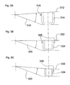
- Fig. 3 is shown in a very simplified way.
- the respective fixed angular position of the lower non-adjustable closing lever is represented by a line 310, 320 and 330.
- the angular position of the adjustable upper closing lever is represented by a line 312, 322 and 332, respectively.
- the position of the closing tools is shown in each case at the moment of the first contact of the second closing tool (punch) with clips of three different sizes (heavily oversubscribed).
- Fig. 3A It can be seen that in the case of a large clip 314, the second closing tool first comes into contact with the inner leg of the clip 314 near the pivot axis. When closing the clip thus initially a torque, represented by the arrow 316, exerted on the clip 314. As a result, an instability of the clip is generated, which was already separated from the subsequent clip strand.
- the medium-sized clip 324 in the example of Fig. 3B both legs come into contact with the second closing tool 323 at the same time.
- the clip 324 is thus evenly loaded when closing, see arrows 326, and stabilized in its position against the first closing tool (die) in its position.
- a small clip 334 is made according to Fig. 3C initially loaded on the side of the pivot axis remote leg and tends due to the resulting torque, represented by the arrow 336, also to tilt.
- the object is achieved in a clip machine of the type mentioned in that the second closing tool along linear guide means is arranged to be movable relative to the first closing tool for closing clips and for adjusting the rest position.
- FIG. 1 shown embodiment of the clip machine 100 has a first drive 110 with a cam 112, from which by means of a cam roller 116, the movement for a lower closing lever 118 is removed. Furthermore, the clip machine 100 has a second drive 130 with a crank 131, from which by means of a lever arm 114, the movement for a second upper closing tool 126 is removed.
- the closing lever 118 is articulated on a pivot axis 122. At its end remote from the pivot axis 122, it carries a first closing tool 124, which in the exemplary embodiment shown is a die.
- a clip strand 132 is fed to the closing lever 118 from above and guided along a guide path 134 beginning in the vicinity of the pivot axis 122 on the clip lever 118 in the direction of the die 124.
- an intermittently acting on the clip strand conveyor 136 is arranged at the front end of the clip lever 118.
- the conveyor 136 raises the clip strand at its end near the die 124, pulls it towards the die and inserts the foremost clip into the die 124.
- the transport of the clip strand takes place substantially in the illustrated position of the lower clip lever 118 when it is in its open position.
- the pivoting movement of the lower clip lever 118 reverses and this feeds the closed position.
- the cam control (due to the curve 112 and optionally a superimposed engine control) directs the closing lever 118 upward until the die 124 approaches the inserted clip of the tube axis 138 marked as a cross 138 up to a predetermined distance. In this position, the foremost clip is pressed against the Schlauchzopf and pressed by its bias in the die.
- the first and second closure dies 124, 126 each have shear means which, when moving into the closed position as a shingling device, cooperate as shearing means for severing the leading clip from the succeeding clip strand 132 before closing this foremost clip around the tubular sheath.
- the separation takes place only when the lower Versch95hebel 118 has already reached its closed position, so that the foremost clip is held by the Schlauchzopf in the die. For this reason, a drive control is provided which allows the second closing tool, the punch 126, to be displaced in the direction of the hose axis 138 with a time offset.
- That upper closure tool 226 becomes as below with reference to Fig. 2 illustrated along linear guide means 220 relative to the first closing tool both for closing clips between the in Fig. 1 shown open position and the closed position and to adjust the rest position.
- the second closing tool 226 is arranged on a linear slide guide 221, which is positively guided by means of two guide rails 222, 224 on a linear path and forms the linear guide means 220 with these.
- the guide means are aligned so that the second closing tool 126 executes a movement directed towards the hose axis 138, cf. Fig. 1 ,
- the movement derived from the drive 230 via the lever 214 is introduced into the carriage guide 220 via a toggle lever arrangement 240.
- the lever 214 engages the knee joint 242 of the toggle lever arrangement 240 and stretches or bends it.
- the toggle lever assembly 240 has a first lever 244, the knee joint 242 distal end of the carriage guide 220 is hinged, and a second lever 245, the distal end of the knee joint 242 hinged to an adjustable in the direction of the linear guide means 220 abutment (not shown) is. Due to the adjustment, characterized by a double arrow 246, the rest position of the second closing tool 226 and thus in particular its distance from the first closing tool 124 in the closed position is set to the respective clip height.
- the second closing tool 226 has two punches 250, 252, between which a knife 254 is arranged.
- This double punch arrangement is associated with a corresponding double die arrangement on the closure lever.
Landscapes
- Life Sciences & Earth Sciences (AREA)
- Engineering & Computer Science (AREA)
- Wood Science & Technology (AREA)
- Zoology (AREA)
- Food Science & Technology (AREA)
- Package Closures (AREA)
- Dovetailed Work, And Nailing Machines And Stapling Machines For Wood (AREA)
- Folding Of Thin Sheet-Like Materials, Special Discharging Devices, And Others (AREA)
- Absorbent Articles And Supports Therefor (AREA)
- Adornments (AREA)
- Portable Nailing Machines And Staplers (AREA)
Claims (5)
- Agrafeuse (100) comprenant un levier de fermeture (118),
un premier outil de fermeture (124), qui est monté sur le levier de fermeture (118) et qui peut basculer avec celui-ci,
un second outil de fermeture (126, 226), le premier outil de fermeture (124) et le second outil de fermeture (126, 226) pouvant être déplacés pour la fermeture d'agrafes l'un par rapport à l'autre entre une position d'ouverture et une position de fermeture,
comprenant une commande d'entraînement pour les outils de fermeture, qui est telle que d'abord le premier outil de fermeture (124) et ensuite le second outil de fermeture (126, 226) viennent dans la position de fermeture et des moyens de réglage, aménagés pour l'ajustage de la position de repos du second outil de fermeture (126, 226) et donc de l'espacement des outils de fermeture dans leur position de fermeture,
le levier de fermeture (118) présentant une glissière de guidage (134) d'une file d'agrafes amenée, qui débouche à proximité du premier outil de fermeture (124) et
les outils de fermeture (124, 126, 226) présentant des moyens de cisaillement, qui sont aménagés pour coopérer pour la séparation d'une agrafe la plus avancée d'une file d'agrafes (132) consécutive juste après la fermeture de l'agrafe séparée comme dispositif de cisaillement,
caractérisée en ce que le second outil de fermeture (126, 226) est disposé dans de façon à pouvoir coulisser le long des moyens de guidage (220) linéaires par rapport au premier outil de fermeture (124). - Agrafeuse (100) selon la revendication 1,
caractérisée par un guidage à coulisseau (221) linéaire, sur lequel est monté le second outil de fermeture (126, 226). - Agrafeuse (100) selon la revendication 2,
caractérisée en ce que le guidage à coulisseau (221) linéaire est orienté perpendiculairement à une ligne de liaison des extrémités de branche d'une agrafe insérée dans le premier outil de fermeture (124). - Agrafeuse (100) selon l'une quelconque des revendications précédentes,
caractérisée en ce que le second outil de fermeture (126, 226) est en liaison avec un entraînement à manivelle (130, 230). - Agrafeuse (100) selon la revendication 4,
caractérisée en ce que l'application de force s'effectue par un entraînement à manivelle (130, 230) au moyen d'un agencement à levier coudé (240), dont le premier levier (244) est articulé par son extrémité éloignée de l'articulation coudée (242) commune au guidage à coulisseau linéaire (221) et dont le second levier (246) est articulé par son extrémité éloignée de l'articulation coudée (242) commune aux moyens de réglage constitués en butée réglable.
Priority Applications (1)
| Application Number | Priority Date | Filing Date | Title |
|---|---|---|---|
| PL06008674T PL1736412T4 (pl) | 2005-06-23 | 2006-04-26 | Maszyna klipsująca |
Applications Claiming Priority (1)
| Application Number | Priority Date | Filing Date | Title |
|---|---|---|---|
| DE102005029227A DE102005029227B4 (de) | 2005-06-23 | 2005-06-23 | Clipmaschine |
Publications (3)
| Publication Number | Publication Date |
|---|---|
| EP1736412A1 EP1736412A1 (fr) | 2006-12-27 |
| EP1736412B1 EP1736412B1 (fr) | 2008-04-30 |
| EP1736412B2 true EP1736412B2 (fr) | 2016-03-16 |
Family
ID=36577470
Family Applications (1)
| Application Number | Title | Priority Date | Filing Date |
|---|---|---|---|
| EP06008674.1A Active EP1736412B2 (fr) | 2005-06-23 | 2006-04-26 | Machine de fermeture par clip |
Country Status (8)
| Country | Link |
|---|---|
| US (1) | US7451582B2 (fr) |
| EP (1) | EP1736412B2 (fr) |
| CN (1) | CN100526163C (fr) |
| BR (1) | BRPI0603050B1 (fr) |
| DE (2) | DE102005029227B4 (fr) |
| ES (1) | ES2304748T5 (fr) |
| PL (1) | PL1736412T4 (fr) |
| RU (1) | RU2386573C2 (fr) |
Families Citing this family (14)
| Publication number | Priority date | Publication date | Assignee | Title |
|---|---|---|---|---|
| DE102007012778B4 (de) | 2007-03-16 | 2010-06-24 | Poly-Clip System Gmbh & Co Kg | Einstellbarer Clipvorschub |
| DE202009007886U1 (de) | 2009-06-04 | 2010-10-21 | Tipper Tie Technopack Gmbh | Vorrichtung zum Setzen U-förmiger Clips |
| DE202009007889U1 (de) | 2009-06-04 | 2010-10-21 | Tipper Tie Technopack Gmbh | Kniehebel in Serie |
| EP2548445B1 (fr) | 2011-07-21 | 2017-11-01 | Poly-clip System GmbH & Co. KG | Machine de fermeture par clip avec entraînement par manivelle réduit |
| DE202012006260U1 (de) * | 2012-06-28 | 2013-09-30 | Tipper Tie Technopack Gmbh | Clipmaschine |
| CN103434682B (zh) * | 2013-09-06 | 2015-02-18 | 陈声佩 | U形卡扣双卡打卡机 |
| US9615589B2 (en) | 2014-10-01 | 2017-04-11 | Poly-Clip System Gmbh & Co. Kg | Decoupled drive units for gathering and over-spreading |
| EA031885B1 (ru) * | 2016-09-02 | 2019-03-29 | Общество с ограниченной ответственностью "Машиностроительное предприятие "КОМПО" | Рабочий блок клипсатора |
| EA032817B1 (ru) | 2016-10-03 | 2019-07-31 | Общество с ограниченной ответственностью "Машиностроительное предприятие "КОМПО" | Клипсатор |
| CN106477110B (zh) * | 2016-11-02 | 2019-01-15 | 黄联福 | 铝钉封口机 |
| EP3685671A1 (fr) | 2019-01-25 | 2020-07-29 | Poly-clip System GmbH & Co. KG | Détection de pince |
| CN111109335A (zh) * | 2020-02-20 | 2020-05-08 | 广东荣业食品有限公司 | 一种腊肠自动化加工装置 |
| RU204064U1 (ru) * | 2021-03-12 | 2021-05-05 | Общество с ограниченной ответственностью «Научно-производственное предприятие «Точная механика» | Устройство для перемещения подвижного ножа клипсатора |
| CN114669791B (zh) * | 2022-04-29 | 2024-01-26 | 西门子工厂自动化工程有限公司 | 剪切控制系统、方法及剪板设备 |
Citations (4)
| Publication number | Priority date | Publication date | Assignee | Title |
|---|---|---|---|---|
| DE1761616A1 (de) † | 1968-06-15 | 1971-07-22 | Niedecker Herbert | U-foermige Verschlussklammer zum Verschliessen von Beuteln und Schlaeuchen |
| US4001926A (en) † | 1975-04-07 | 1977-01-11 | Rheem Manufacturing Company | Double clipper, single piston operated device |
| DE29613336U1 (de) † | 1996-08-01 | 1996-09-19 | Waelchli Hans | Vorrichtung zum Bilden und Verschließen schlauchförmiger Verpackungen |
| DE19953694B4 (de) † | 1999-11-09 | 2004-03-11 | Poly-Clip System Gmbh & Co. Kg | Verschliessvorrichtung für schlauchförmige Verpackungen |
Family Cites Families (16)
| Publication number | Priority date | Publication date | Assignee | Title |
|---|---|---|---|---|
| US2880419A (en) * | 1957-11-22 | 1959-04-07 | Tipper Tie Products Of New Jer | Apparatus for fastening casings with staple-like fasteners |
| US3061838A (en) * | 1958-04-24 | 1962-11-06 | Joseph J Frank | Apparatus for sealing stuffed flexible casings |
| US3383746A (en) * | 1965-09-22 | 1968-05-21 | Grace W R & Co | Device for securing fasteners on flexible containers |
| US3377692A (en) * | 1966-10-13 | 1968-04-16 | Rheem Mfg Co | Clipping apparatus |
| DE1511754B2 (de) * | 1966-10-28 | 1976-07-29 | Rheem International, Inc., New York, N. Y. (V.StA.) | Vorrichtung zum anbringen von verschluss-klammern an verpackungsbeuteln, saecken oder dergleichen |
| US3791191A (en) * | 1971-11-29 | 1974-02-12 | Diamond Die & Mold Co | Press pressure and closed position control |
| FR2258951B1 (fr) * | 1974-01-28 | 1977-03-04 | Jambon Anciens Ateliers | |
| DE2424979A1 (de) * | 1974-05-22 | 1975-12-11 | Karl Schnell | Vorrichtung zum verschliessen elastischer packungen, insbesondere schlauchartiger huellen |
| DE2647598C3 (de) * | 1976-10-21 | 1982-04-15 | Technopack Ewald Hagedorn Kg, 2000 Hamburg | Vorrichtung zum Verschließen einer sackartigen Hülle mit einem Klipp |
| GB2100183B (en) * | 1981-06-17 | 1984-11-07 | Hugan Ltd | Toggle press |
| US4934173A (en) * | 1989-03-17 | 1990-06-19 | Amp Incorporated | Stamping and forming machine having toggles for reciprocating the tooling assemblies |
| DE59001115D1 (de) * | 1989-09-21 | 1993-05-06 | Niedecker Herbert | Verfahren und vorrichtungen zum verschliessen von verpackungshuellen aus biegsamen material. |
| CN2248682Y (zh) * | 1996-01-23 | 1997-03-05 | 石家庄市食品四厂 | 软包装食品双卡结扎机 |
| DE19738298C1 (de) * | 1997-09-02 | 1999-04-08 | Poly Clip System Gmbh & Co Kg | Verfahren zum Einrichten einer Verschließmaschine und Vorrichtung zum Verschließen von Verschlußklammern |
| CN2350985Y (zh) * | 1999-01-22 | 1999-12-01 | 中国肉类食品综合研究中心 | 一种拉伸结扎机 |
| DE10131807C1 (de) * | 2001-06-30 | 2002-11-07 | Poly Clip System Gmbh & Co Kg | Portionierungsvorrichtung |
-
2005
- 2005-06-23 DE DE102005029227A patent/DE102005029227B4/de not_active Expired - Fee Related
-
2006
- 2006-04-26 ES ES06008674.1T patent/ES2304748T5/es active Active
- 2006-04-26 EP EP06008674.1A patent/EP1736412B2/fr active Active
- 2006-04-26 DE DE502006000703T patent/DE502006000703D1/de active Active
- 2006-04-26 PL PL06008674T patent/PL1736412T4/pl unknown
- 2006-05-22 US US11/419,631 patent/US7451582B2/en active Active
- 2006-06-13 CN CNB2006100873978A patent/CN100526163C/zh active Active
- 2006-06-21 BR BRPI0603050-5A patent/BRPI0603050B1/pt active IP Right Grant
- 2006-06-22 RU RU2006122357/12A patent/RU2386573C2/ru active
Patent Citations (4)
| Publication number | Priority date | Publication date | Assignee | Title |
|---|---|---|---|---|
| DE1761616A1 (de) † | 1968-06-15 | 1971-07-22 | Niedecker Herbert | U-foermige Verschlussklammer zum Verschliessen von Beuteln und Schlaeuchen |
| US4001926A (en) † | 1975-04-07 | 1977-01-11 | Rheem Manufacturing Company | Double clipper, single piston operated device |
| DE29613336U1 (de) † | 1996-08-01 | 1996-09-19 | Waelchli Hans | Vorrichtung zum Bilden und Verschließen schlauchförmiger Verpackungen |
| DE19953694B4 (de) † | 1999-11-09 | 2004-03-11 | Poly-Clip System Gmbh & Co. Kg | Verschliessvorrichtung für schlauchförmige Verpackungen |
Also Published As
| Publication number | Publication date |
|---|---|
| ES2304748T3 (es) | 2008-10-16 |
| PL1736412T3 (pl) | 2008-09-30 |
| EP1736412B1 (fr) | 2008-04-30 |
| DE502006000703D1 (de) | 2008-06-12 |
| PL1736412T4 (pl) | 2022-05-16 |
| BRPI0603050A (pt) | 2007-02-21 |
| ES2304748T5 (es) | 2016-04-25 |
| DE102005029227A1 (de) | 2006-12-28 |
| US7451582B2 (en) | 2008-11-18 |
| PL1736412T5 (pl) | 2016-12-30 |
| CN1884005A (zh) | 2006-12-27 |
| EP1736412A1 (fr) | 2006-12-27 |
| US20060292970A1 (en) | 2006-12-28 |
| DE102005029227B4 (de) | 2007-11-08 |
| RU2386573C2 (ru) | 2010-04-20 |
| CN100526163C (zh) | 2009-08-12 |
| BRPI0603050B1 (pt) | 2022-06-07 |
| RU2006122357A (ru) | 2008-01-10 |
Similar Documents
| Publication | Publication Date | Title |
|---|---|---|
| EP1736412B2 (fr) | Machine de fermeture par clip | |
| EP1886573B1 (fr) | Machine de fermeture par clip | |
| DE102007011422B3 (de) | Automatische Spreizverstellung | |
| EP2051909B1 (fr) | Machine de cerclage par bande | |
| EP1844659B1 (fr) | Nouage direct d'un dispositif d'agrafe de saucisson et d'alimentation de saucisson | |
| EP1969945B1 (fr) | Procédé et dispositif de fermeture commandée d'au moins un clip autour d'une section tressée exempte de produit de remplissage entre deux sections tressées fermées par un emballage | |
| EP1847177A1 (fr) | Ecartement supplémentaire doté d'une seconde longueur de boyau | |
| EP3672875B1 (fr) | Dispositif d'emballage et procédé destiné à emballer des objets | |
| EP1969946B1 (fr) | Avancement à clip réglable | |
| WO2013079129A1 (fr) | Vanne à manchon | |
| EP2258622B1 (fr) | Dispositif d'installation de clips en forme de U | |
| EP2186415A1 (fr) | Composant de refoulement pour une machine à clips | |
| DE2730121C3 (de) | Verfahren zum Abteilen von Packungen von einem gefüllten Schlauch | |
| DE102017207585B4 (de) | Drahtumformmaschine und Verfahren zur Herstellung von Umformteilen aus Draht | |
| EP2335486A2 (fr) | Dispositif de fermeture pour la formation d'emballages en forme de saucisses | |
| DE19825106C1 (de) | Vorrichtung zum Markieren von Verschlußklammern | |
| DE102004022716B4 (de) | Vorrichtung zum Herstellen von gefüllten, verschlossenen Schlauchbeutelpackungen | |
| DE19519591C2 (de) | Vorrichtung zum Herstellen von gefüllten verschlossenen Schlauchbeutelpackungen | |
| EP0937403B1 (fr) | Procédé et dispositif à double-clip pour emballages tubulaires | |
| EP1348571B1 (fr) | Dispositif pour relier des éléments plats empilés | |
| EP0963698B1 (fr) | Dispositif pour diviser un tube d'emballage rempli en unités | |
| EP2840049B1 (fr) | Dispositif de transport d'un prospectus | |
| EP2457445B1 (fr) | Dispositif de fermeture pour la formation d'emballages en forme de saucisses | |
| DE2123875A1 (en) | Sausage skin clamping machine - with two pairs of counter operating jaws to eliminate skin tearing | |
| DE2254527A1 (de) | Verfahren zum versetzten uebereinanderbringen von je zwei folien vorgegebener laenge pro arbeitszyklus |
Legal Events
| Date | Code | Title | Description |
|---|---|---|---|
| PUAI | Public reference made under article 153(3) epc to a published international application that has entered the european phase |
Free format text: ORIGINAL CODE: 0009012 |
|
| AK | Designated contracting states |
Kind code of ref document: A1 Designated state(s): AT BE BG CH CY CZ DE DK EE ES FI FR GB GR HU IE IS IT LI LT LU LV MC NL PL PT RO SE SI SK TR |
|
| AX | Request for extension of the european patent |
Extension state: AL BA HR MK YU |
|
| 17P | Request for examination filed |
Effective date: 20070627 |
|
| AKX | Designation fees paid |
Designated state(s): CH DE ES IT LI NL PL |
|
| GRAP | Despatch of communication of intention to grant a patent |
Free format text: ORIGINAL CODE: EPIDOSNIGR1 |
|
| GRAS | Grant fee paid |
Free format text: ORIGINAL CODE: EPIDOSNIGR3 |
|
| GRAA | (expected) grant |
Free format text: ORIGINAL CODE: 0009210 |
|
| AK | Designated contracting states |
Kind code of ref document: B1 Designated state(s): CH DE ES IT LI NL PL |
|
| REG | Reference to a national code |
Ref country code: CH Ref legal event code: EP |
|
| REF | Corresponds to: |
Ref document number: 502006000703 Country of ref document: DE Date of ref document: 20080612 Kind code of ref document: P |
|
| REG | Reference to a national code |
Ref country code: CH Ref legal event code: NV Representative=s name: ZIMMERLI, WAGNER & PARTNER AG |
|
| REG | Reference to a national code |
Ref country code: PL Ref legal event code: T3 |
|
| REG | Reference to a national code |
Ref country code: ES Ref legal event code: FG2A Ref document number: 2304748 Country of ref document: ES Kind code of ref document: T3 |
|
| PLBI | Opposition filed |
Free format text: ORIGINAL CODE: 0009260 |
|
| PLAX | Notice of opposition and request to file observation + time limit sent |
Free format text: ORIGINAL CODE: EPIDOSNOBS2 |
|
| 26 | Opposition filed |
Opponent name: TIPPER TIE ALPINA AG Effective date: 20090129 |
|
| NLR1 | Nl: opposition has been filed with the epo |
Opponent name: TIPPER TIE ALPINA AG |
|
| PLBB | Reply of patent proprietor to notice(s) of opposition received |
Free format text: ORIGINAL CODE: EPIDOSNOBS3 |
|
| REG | Reference to a national code |
Ref country code: CH Ref legal event code: PFA Owner name: POLY-CLIP SYSTEM GMBH & CO. KG Free format text: POLY-CLIP SYSTEM GMBH & CO. KG#WESTERBACHSTRASSE 45#60489 FRANKFURT AM MAIN (DE) -TRANSFER TO- POLY-CLIP SYSTEM GMBH & CO. KG#WESTERBACHSTRASSE 45#60489 FRANKFURT AM MAIN (DE) |
|
| RDAF | Communication despatched that patent is revoked |
Free format text: ORIGINAL CODE: EPIDOSNREV1 |
|
| APAH | Appeal reference modified |
Free format text: ORIGINAL CODE: EPIDOSCREFNO |
|
| APBM | Appeal reference recorded |
Free format text: ORIGINAL CODE: EPIDOSNREFNO |
|
| APBP | Date of receipt of notice of appeal recorded |
Free format text: ORIGINAL CODE: EPIDOSNNOA2O |
|
| APBQ | Date of receipt of statement of grounds of appeal recorded |
Free format text: ORIGINAL CODE: EPIDOSNNOA3O |
|
| REG | Reference to a national code |
Ref country code: CH Ref legal event code: PFA Owner name: POLY-CLIP SYSTEM GMBH & CO. KG Free format text: POLY-CLIP SYSTEM GMBH & CO. KG#WESTERBACHSTRASSE 45#60489 FRANKFURT AM MAIN (DE) -TRANSFER TO- POLY-CLIP SYSTEM GMBH & CO. KG#NIEDECKERSTRASSE 1#65795 HATTERSHEIM (DE) |
|
| RAP2 | Party data changed (patent owner data changed or rights of a patent transferred) |
Owner name: POLY-CLIP SYSTEM GMBH & CO. KG |
|
| PLAB | Opposition data, opponent's data or that of the opponent's representative modified |
Free format text: ORIGINAL CODE: 0009299OPPO |
|
| R26 | Opposition filed (corrected) |
Opponent name: TIPPER TIE ALPINA GMBH Effective date: 20090129 |
|
| REG | Reference to a national code |
Ref country code: DE Ref legal event code: R082 Ref document number: 502006000703 Country of ref document: DE Representative=s name: EISENFUEHR, SPEISER & PARTNER, DE |
|
| REG | Reference to a national code |
Ref country code: DE Ref legal event code: R082 Ref document number: 502006000703 Country of ref document: DE Representative=s name: EISENFUEHR SPEISER PATENTANWAELTE RECHTSANWAEL, DE Effective date: 20130827 Ref country code: DE Ref legal event code: R081 Ref document number: 502006000703 Country of ref document: DE Owner name: POLY-CLIP SYSTEM GMBH & CO. KG, DE Free format text: FORMER OWNER: POLY-CLIP SYSTEM GMBH & CO. KG, 60489 FRANKFURT, DE Effective date: 20130827 |
|
| REG | Reference to a national code |
Ref country code: CH Ref legal event code: NV Representative=s name: WAGNER PATENT AG, CH |
|
| APBY | Invitation to file observations in appeal sent |
Free format text: ORIGINAL CODE: EPIDOSNOBA2O |
|
| APBU | Appeal procedure closed |
Free format text: ORIGINAL CODE: EPIDOSNNOA9O |
|
| PUAH | Patent maintained in amended form |
Free format text: ORIGINAL CODE: 0009272 |
|
| STAA | Information on the status of an ep patent application or granted ep patent |
Free format text: STATUS: PATENT MAINTAINED AS AMENDED |
|
| 27A | Patent maintained in amended form |
Effective date: 20160316 |
|
| AK | Designated contracting states |
Kind code of ref document: B2 Designated state(s): CH DE ES IT LI NL PL |
|
| REG | Reference to a national code |
Ref country code: DE Ref legal event code: R102 Ref document number: 502006000703 Country of ref document: DE |
|
| REG | Reference to a national code |
Ref country code: CH Ref legal event code: AELC |
|
| REG | Reference to a national code |
Ref country code: ES Ref legal event code: DC2A Ref document number: 2304748 Country of ref document: ES Kind code of ref document: T5 Effective date: 20160425 |
|
| REG | Reference to a national code |
Ref country code: NL Ref legal event code: FP |
|
| P01 | Opt-out of the competence of the unified patent court (upc) registered |
Effective date: 20230519 |
|
| PGFP | Annual fee paid to national office [announced via postgrant information from national office to epo] |
Ref country code: IT Payment date: 20230428 Year of fee payment: 18 Ref country code: ES Payment date: 20230517 Year of fee payment: 18 Ref country code: DE Payment date: 20230509 Year of fee payment: 18 Ref country code: CH Payment date: 20230502 Year of fee payment: 18 |
|
| PGFP | Annual fee paid to national office [announced via postgrant information from national office to epo] |
Ref country code: PL Payment date: 20230209 Year of fee payment: 18 |
|
| PGFP | Annual fee paid to national office [announced via postgrant information from national office to epo] |
Ref country code: NL Payment date: 20240422 Year of fee payment: 19 |