EP1736412B2 - Clipping machine - Google Patents
Clipping machine Download PDFInfo
- Publication number
- EP1736412B2 EP1736412B2 EP06008674.1A EP06008674A EP1736412B2 EP 1736412 B2 EP1736412 B2 EP 1736412B2 EP 06008674 A EP06008674 A EP 06008674A EP 1736412 B2 EP1736412 B2 EP 1736412B2
- Authority
- EP
- European Patent Office
- Prior art keywords
- closure
- clip
- tool
- lever
- closing
- Prior art date
- Legal status (The legal status is an assumption and is not a legal conclusion. Google has not performed a legal analysis and makes no representation as to the accuracy of the status listed.)
- Active
Links
- 238000010008 shearing Methods 0.000 claims description 4
- 210000002414 leg Anatomy 0.000 description 8
- 210000000629 knee joint Anatomy 0.000 description 3
- 238000000034 method Methods 0.000 description 3
- 238000004806 packaging method and process Methods 0.000 description 3
- 238000013459 approach Methods 0.000 description 2
- 239000000463 material Substances 0.000 description 2
- 235000013580 sausages Nutrition 0.000 description 2
- XAGFODPZIPBFFR-UHFFFAOYSA-N aluminium Chemical compound [Al] XAGFODPZIPBFFR-UHFFFAOYSA-N 0.000 description 1
- 229910052782 aluminium Inorganic materials 0.000 description 1
- 230000003111 delayed effect Effects 0.000 description 1
- 230000001419 dependent effect Effects 0.000 description 1
- 238000006073 displacement reaction Methods 0.000 description 1
- 210000000936 intestine Anatomy 0.000 description 1
- 239000007788 liquid Substances 0.000 description 1
- 239000007937 lozenge Substances 0.000 description 1
- 238000007789 sealing Methods 0.000 description 1
- 238000000926 separation method Methods 0.000 description 1
Images


Classifications
-
- A—HUMAN NECESSITIES
- A22—BUTCHERING; MEAT TREATMENT; PROCESSING POULTRY OR FISH
- A22C—PROCESSING MEAT, POULTRY, OR FISH
- A22C11/00—Sausage making ; Apparatus for handling or conveying sausage products during manufacture
- A22C11/12—Apparatus for tying sausage skins ; Clipping sausage skins
- A22C11/125—Apparatus for tying sausage skins ; Clipping sausage skins by clipping; Removal of clips
-
- B—PERFORMING OPERATIONS; TRANSPORTING
- B65—CONVEYING; PACKING; STORING; HANDLING THIN OR FILAMENTARY MATERIAL
- B65B—MACHINES, APPARATUS OR DEVICES FOR, OR METHODS OF, PACKAGING ARTICLES OR MATERIALS; UNPACKING
- B65B51/00—Devices for, or methods of, sealing or securing package folds or closures; Devices for gathering or twisting wrappers, or necks of bags
- B65B51/04—Applying separate sealing or securing members, e.g. clips
Definitions
- the invention relates to a clipping machine with a closing lever, a first closing tool, which is arranged on the closing lever and pivotally mounted therewith, a second closing tool, wherein the first closing tool and the second closing tool for closing clips relative to each other between an open position and a closed position movable with a drive control for the closing tools, which is arranged so that first the first closing tool and then the second closing tool is moved to the closed position, and with adjusting means adapted to adjust the rest position of the second closing tool and thus the distance of the closing tools, in particular in its closed position (shutter distance).
- first closing lever and a second closing lever for the second closing tool are pivoted from their open position to a generally common pivot axis in the closed position.
- the closing tools comprise in pairs in each case a punch and a die between which the clip is deformed until it reaches the closed position (reversal point of the movement). After closing, the closing tools are moved back into their initial or open position by the locking lever are pivoted back from its closed position to the open position.
- Such clip machines usually have a crank drive or a cam drive for the movement of the closing lever, in which a control cam on a cam is tapped by means of a cam roller.
- a simple lever or a toggle lever arrangement is used, which is bent in the open position and stretched in the closed position.
- clips are used, which are made of an embossed aluminum wire strand each still connected at their leg ends integrally connected to each other so that they span a common plane, the clip plane. In this way they are fed to the closing tools. As is known, this takes place along a guideway provided on the (lower) closing lever for the first closing tool, which begins in the region of the pivot axis of the closing lever and opens into the area of the associated closing tool.
- the foremost clip is known to be supplied to the first (lower) closing tool by an intermittently engaging feed means during transport of the clip strand. As long as the foremost clip is still connected to the subsequent strand of the clip, it is stably held by it in the lower closing tool, which is typically formed by a die.
- the pivotal movement of the closing lever are executed by means of the drive control - for example in the form of staggered curves on a cam and / or an electronic time control - with a time delay.
- the lower locking lever is pivoted to its (upper) closing or Hubend ein. In this position, the foremost clip is pressed against the Schlauchzopf and is clamped between this and the first closing tool.
- the second (upper) closing tool moves to the lower closing tool by pivoting about the same pivot axis.
- the foremost clip is thereby separated from the following clip strand by means of a shearing device provided on the closing tools.
- the foremost clip is free and is only pressed by the tension of the hose braid against the lower closing tool.
- the clip is deformed by a further approach of the upper closing tool to the lower closing tool until the closing tools have approached to the clip height and the clip is closed around the Schlauchzopf around.
- the closure distance must be adjusted because this is the measure to which the closure element is compressed when closing (hereinafter called clip height), is authoritative.
- clip height the measure to which the closure element is compressed when closing
- the rest position of at least one of Closing tools and thus the closure distance changed preferably serves an adjustable articulation point on the abutment of the toggle lever for the second closing tool as adjustment.
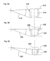
- Fig. 3 is shown in a very simplified way.
- the respective fixed angular position of the lower non-adjustable closing lever is represented by a line 310, 320 and 330.
- the angular position of the adjustable upper closing lever is represented by a line 312, 322 and 332, respectively.
- the position of the closing tools is shown in each case at the moment of the first contact of the second closing tool (punch) with clips of three different sizes (heavily oversubscribed).
- Fig. 3A It can be seen that in the case of a large clip 314, the second closing tool first comes into contact with the inner leg of the clip 314 near the pivot axis. When closing the clip thus initially a torque, represented by the arrow 316, exerted on the clip 314. As a result, an instability of the clip is generated, which was already separated from the subsequent clip strand.
- the medium-sized clip 324 in the example of Fig. 3B both legs come into contact with the second closing tool 323 at the same time.
- the clip 324 is thus evenly loaded when closing, see arrows 326, and stabilized in its position against the first closing tool (die) in its position.
- a small clip 334 is made according to Fig. 3C initially loaded on the side of the pivot axis remote leg and tends due to the resulting torque, represented by the arrow 336, also to tilt.
- the object is achieved in a clip machine of the type mentioned in that the second closing tool along linear guide means is arranged to be movable relative to the first closing tool for closing clips and for adjusting the rest position.
- FIG. 1 shown embodiment of the clip machine 100 has a first drive 110 with a cam 112, from which by means of a cam roller 116, the movement for a lower closing lever 118 is removed. Furthermore, the clip machine 100 has a second drive 130 with a crank 131, from which by means of a lever arm 114, the movement for a second upper closing tool 126 is removed.
- the closing lever 118 is articulated on a pivot axis 122. At its end remote from the pivot axis 122, it carries a first closing tool 124, which in the exemplary embodiment shown is a die.
- a clip strand 132 is fed to the closing lever 118 from above and guided along a guide path 134 beginning in the vicinity of the pivot axis 122 on the clip lever 118 in the direction of the die 124.
- an intermittently acting on the clip strand conveyor 136 is arranged at the front end of the clip lever 118.
- the conveyor 136 raises the clip strand at its end near the die 124, pulls it towards the die and inserts the foremost clip into the die 124.
- the transport of the clip strand takes place substantially in the illustrated position of the lower clip lever 118 when it is in its open position.
- the pivoting movement of the lower clip lever 118 reverses and this feeds the closed position.
- the cam control (due to the curve 112 and optionally a superimposed engine control) directs the closing lever 118 upward until the die 124 approaches the inserted clip of the tube axis 138 marked as a cross 138 up to a predetermined distance. In this position, the foremost clip is pressed against the Schlauchzopf and pressed by its bias in the die.
- the first and second closure dies 124, 126 each have shear means which, when moving into the closed position as a shingling device, cooperate as shearing means for severing the leading clip from the succeeding clip strand 132 before closing this foremost clip around the tubular sheath.
- the separation takes place only when the lower Versch95hebel 118 has already reached its closed position, so that the foremost clip is held by the Schlauchzopf in the die. For this reason, a drive control is provided which allows the second closing tool, the punch 126, to be displaced in the direction of the hose axis 138 with a time offset.
- That upper closure tool 226 becomes as below with reference to Fig. 2 illustrated along linear guide means 220 relative to the first closing tool both for closing clips between the in Fig. 1 shown open position and the closed position and to adjust the rest position.
- the second closing tool 226 is arranged on a linear slide guide 221, which is positively guided by means of two guide rails 222, 224 on a linear path and forms the linear guide means 220 with these.
- the guide means are aligned so that the second closing tool 126 executes a movement directed towards the hose axis 138, cf. Fig. 1 ,
- the movement derived from the drive 230 via the lever 214 is introduced into the carriage guide 220 via a toggle lever arrangement 240.
- the lever 214 engages the knee joint 242 of the toggle lever arrangement 240 and stretches or bends it.
- the toggle lever assembly 240 has a first lever 244, the knee joint 242 distal end of the carriage guide 220 is hinged, and a second lever 245, the distal end of the knee joint 242 hinged to an adjustable in the direction of the linear guide means 220 abutment (not shown) is. Due to the adjustment, characterized by a double arrow 246, the rest position of the second closing tool 226 and thus in particular its distance from the first closing tool 124 in the closed position is set to the respective clip height.
- the second closing tool 226 has two punches 250, 252, between which a knife 254 is arranged.
- This double punch arrangement is associated with a corresponding double die arrangement on the closure lever.
Description
Die Erfindung betrifft eine Clipmaschine mit einem Verschließhebel, einem ersten Verschließwerkzeug, welches an dem Verschließhebel angeordnet und mit diesem schwenkbar gelagert ist, einem zweiten Verschließwerkzeug, wobei das erste Verschließwerkzeug und das zweite Verschließwerkzeug zum Verschließen von Clips relativ zueinander zwischen einer Öffnungsstellung und einer Verschlussstellung bewegbar sind, mit einer Antriebssteuerung für die Verschließwerkzeuge, die so eingerichtet ist, dass zuerst das erste Verschließwerkzeug und dann das zweite Verschließwerkzeug in die Verschlussstellung gefahren wird, und mit Einstellmitteln, eingerichtet zum Einstellen der Ruhelage des zweiten Verschließwerkzeugs und somit des Abstands der Verschließwerkzeuge, insbesondere in ihrer Verschlussstellung (Verschlussabstand).The invention relates to a clipping machine with a closing lever, a first closing tool, which is arranged on the closing lever and pivotally mounted therewith, a second closing tool, wherein the first closing tool and the second closing tool for closing clips relative to each other between an open position and a closed position movable with a drive control for the closing tools, which is arranged so that first the first closing tool and then the second closing tool is moved to the closed position, and with adjusting means adapted to adjust the rest position of the second closing tool and thus the distance of the closing tools, in particular in its closed position (shutter distance).
Mit Clipmaschinen der genannten Art werden typischerweise mit flüssigem bis zähpastösem oder auch (teilweise) granularem Inhalt befüllte Beutet oder schlauchförmige Verpackungen (auch Schlauchhülle oder Darm genannt) verschlossen. Zunächst wird bei diesem Vorgang das Füllgut in die Verpackung eingebracht und im Fall einer schlauchförmigen Verpackung danach mittels Verdrängelementen in Portionen abgeteilt. Die Verdrängelemente schnüren dazu die Schlauchhülle in radialer Richtung ein und verdrängen das in dem Einschnürbereich befindliche Füllgut in axialer Richtung, bezogen auf die Schlauchachse. Im Einschnürbereich wird so ein Schlauchzopf gebildet. Auf den gebildeten Schlauchzopf werden im nächsten Arbeitstakt ein, oder im Fall einer Doppelclipanordnung zwei, Verschlusselemente (Clips) mittels der zwei (bzw. vier) gegeneinander bewegten Verschließwerkzeuge aufgebracht. Hierzu werden der erste Verschließhebel und ein zweiter Verschließhebel für das zweite Verschließwerkzeug aus ihrer Öffnungsstellung um eine in der Regel gemeinsame Schwenkachse in die Verschlussstellung geschwenkt. Die Verschließwerkzeuge umfassen paarweise jeweils einen Stempel und eine Matrize zwischen welchen der Clip bis zum Erreichen der Verschlussstellung (Umkehrpunkt der Bewegung) umgeformt wird. Nach dem Verschließen werden die Verschließwerkzeuge in ihrer Ausgangs- oder Öffnungsstellung zurückbewegt, indem die Verschließhebel aus ihrer Verschlussstellung in die Öffnungsstellung zurück geschwenkt werden.With clipping machines of the type mentioned are typically filled with liquid to viscous or (partially) granular content filled lozenges or tubular packaging (also called tubular casing or intestine). First, in this process, the contents are introduced into the package and then divided in the case of a tubular packaging by means of displacement elements in portions. The Verdrängelemente lace the tubular casing in the radial direction and displace the filling material located in the constriction area in the axial direction, relative to the tube axis. In the constriction so a Schlauchzopf is formed. On the formed hose plait, in the next work cycle, or in the case of a double clip arrangement, two closure elements (clips) are applied by means of the two (or four) closing tools which move relative to one another. For this purpose, the first closing lever and a second closing lever for the second closing tool are pivoted from their open position to a generally common pivot axis in the closed position. The closing tools comprise in pairs in each case a punch and a die between which the clip is deformed until it reaches the closed position (reversal point of the movement). After closing, the closing tools are moved back into their initial or open position by the locking lever are pivoted back from its closed position to the open position.
Solche Clipmaschinen weisen meist einen Kurbelantrieb oder einen Kurvenantrieb für die Bewegung der Verschließhebel auf, bei dem mittels einer Kurvenrolle eine Steuerkurve auf einer Kurvenscheibe abgegriffen wird. Zur Übertragung der Bewegung auf die Verschließhebel kommen beispielsweise ein einfacher Hebel oder eine Kniehebelanordnung zum Einsatz, die in der Öffnungsstellung gebeugt und in der Verschlussstellung gestreckt ist.Such clip machines usually have a crank drive or a cam drive for the movement of the closing lever, in which a control cam on a cam is tapped by means of a cam roller. To transmit the movement to the closing lever, for example, a simple lever or a toggle lever arrangement is used, which is bent in the open position and stretched in the closed position.
Bei den eingangs beschriebenen Clipmaschinen kommen typischerweise Clips zum Einsatz, die aus einem geprägten Aluminiumdrahtstrang gefertigt jeweils noch an ihren Schenkelenden einstückig zusammenhängend so miteinander verbunden sind, dass sie eine gemeinsame Ebene, die Klammerebene, aufspannen. Auf diese Weise werden sie den Verschließwerkzeugen zugeführt. Dies geschieht bekanntermaßen entlang einer an dem (unteren) Verschließhebel für das erste Verschließwerkzeug vorgesehenen Führungsbahn, die im Bereich der Schwenkachse des Verschließhebels beginnt und in den Bereich des zugeordneten Verschließwerkzeugs mündet.In the clip machines described above typically clips are used, which are made of an embossed aluminum wire strand each still connected at their leg ends integrally connected to each other so that they span a common plane, the clip plane. In this way they are fed to the closing tools. As is known, this takes place along a guideway provided on the (lower) closing lever for the first closing tool, which begins in the region of the pivot axis of the closing lever and opens into the area of the associated closing tool.
Der vorderste Clip wird beim Transport des Clipstrangs dem ersten (unteren) Verschließwerkzeug bekanntermaßen von einem intermittierend eingreifenden Vorschubmittel zugeführt. Solange der vorderste Clip noch mit dem nachfolgenden Clipstrang verbunden ist, wird er von diesem stabil in dem unteren Verschließwerkzeug, welches typischerweise von einer Matrize gebildet wird, gehalten.The foremost clip is known to be supplied to the first (lower) closing tool by an intermittently engaging feed means during transport of the clip strand. As long as the foremost clip is still connected to the subsequent strand of the clip, it is stably held by it in the lower closing tool, which is typically formed by a die.
Die Schwenkbewegung der Verschließhebel werden mittels der Antriebssteuerung - beispielsweise in Form versetzter Kurven auf einer Kurvenscheibe und/oder über eine elektronische Zeitsteuerung - zeitversetzt ausgeführt. Zunächst wird der untere Verschließhebel in seine (obere) Verschluss- oder Hubendstellung geschwenkt. In dieser Stellung wird der vorderste Clip gegen den Schlauchzopf gedrückt und ist zwischen diesem und dem ersten Verschließwerkzeug eingespannt. Zeitversetzt, d.h. noch während der untere Verschließhebel in dieser Stellung verharrt, bewegt sich das zweite (obere) Verschließwerkzeug auf das untere Verschließwerkzeug durch eine Schwenkung um dieselbe Schwenkachse zu.The pivotal movement of the closing lever are executed by means of the drive control - for example in the form of staggered curves on a cam and / or an electronic time control - with a time delay. First, the lower locking lever is pivoted to its (upper) closing or Hubendstellung. In this position, the foremost clip is pressed against the Schlauchzopf and is clamped between this and the first closing tool. Time delayed, i. even while the lower locking lever remains in this position, the second (upper) closing tool moves to the lower closing tool by pivoting about the same pivot axis.
Unmittelbar vor dem Verschließen des Clips wird dadurch zunächst mittels einer an den Verschließwerkzeugen vorgesehenen Schervorrichtung der vorderste Clip von dem nachfolgenden Clipstrang abgetrennt. In diesem Moment ist der vorderste Clip frei und wird nur noch durch die Spannung des Schlauchzopfs gegen das untere Verschließwerkzeug angedrückt. Sodann wird der Clip durch eine weitere Annäherung des oberen Verschließwerkzeugs an das untere Verschließwerkzeug verformt, bis sich die Verschließwerkzeuge bis auf die Klammerhöhe angenähert haben und der Clip um den Schlauchzopf herum verschlossen ist.Immediately before closing the clip, the foremost clip is thereby separated from the following clip strand by means of a shearing device provided on the closing tools. At this moment, the foremost clip is free and is only pressed by the tension of the hose braid against the lower closing tool. Then, the clip is deformed by a further approach of the upper closing tool to the lower closing tool until the closing tools have approached to the clip height and the clip is closed around the Schlauchzopf around.
Wenn die Clipmaschine für eine Vielzahl von verschiedenen Wurstprodukten und Verpackungshüllen eingesetzt werden soll, kommen für den jeweiligen Bedarf angepasste, unterschiedliche Clips zum Einsatz, die sich sowohl in ihrer Festigkeit als auch in ihrer Größe, z.B. Schenkellänge und/oder Materialstärke, unterscheiden. Entsprechend muss der Verschlussabstand angepasst werden, da dieser für das Maß, auf dass das Verschlusselement beim Verschließen zusammengedrückt wird (im Folgenden Klammerhöhe genannt), maßgebend ist. Dazu wird bekanntermaßen die Ruhelage wenigstens eines der Verschließwerkzeuge und somit der Verschlussabstand verändert. Dazu dient vorzugsweise ein einstellbarer Anlenkpunkt am Gegenlager des Kniehebels für das zweite Verschließwerkzeug als Einstellmittel.If the clip machine is to be used for a large number of different sausage products and packaging casings, different clips adapted to the respective requirement are used, which differ both in their strength and in their size, eg leg length and / or material thickness. Accordingly, the closure distance must be adjusted because this is the measure to which the closure element is compressed when closing (hereinafter called clip height), is authoritative. For this purpose, it is known that the rest position of at least one of Closing tools and thus the closure distance changed. For this purpose, preferably serves an adjustable articulation point on the abutment of the toggle lever for the second closing tool as adjustment.
Werden Clips unterschiedlicher Größe verwendet und zu diesem Zweck die Verschlussstellung verstellt, so ändert sich der Öffnungswinkel der beiden relativ zueinander beweglichen Verschließhebel. Dies hat zur Folge, dass je nach Schenkellänge des unverformten Clips das obere Verschließwerkzeug nicht gleichzeitig an beiden Schenkeln angreift. Dies ist in
In
Solche unkontrollierbaren Kipp- oder Drehmomente, die auf den abgetrennten Clip wirken und somit eine Fehlerquelle darstellen, gilt es zu vermeiden und den Verschließvorgang dadurch sicherer zu gestalten.Such uncontrollable tilting or torques acting on the severed clip and thus represent a source of error, it is necessary to avoid and make the closing process safer.
Die Aufgabe wird erfindungsgemäß bei einer Clipmaschine der eingangs genannten Art dadurch gelöst, dass das zweite Verschließwerkzeug entlang linearer Führungsmittel relativ zum ersten Verschließwerkzeug zum Verschließen von Clips und zum Einstellen der Ruhelage verfahrbar angeordnet ist.The object is achieved in a clip machine of the type mentioned in that the second closing tool along linear guide means is arranged to be movable relative to the first closing tool for closing clips and for adjusting the rest position.
Da erfindungsgemäß keine Einstellmittel für die Ruheposition des ersten Verschließwerkzeug vorgesehen sind, ist dessen Verschlussstellung durch den Umkehrpunkt der Verschließhebelbewegung festgelegt. Wird die Bewegung des zweiten Verschließwerkzeugs linear ausgeführt, vorzugsweise senkrecht auf eine gedachte Verbindungslinie der Schenkelenden eines in das erste Verschließwerkzeug (die Matrize) eingelegten Clips ausgerichtet, wird die geschilderte Fehlerquelle vermieden, da sich die Winkelstellung der Verschließwerkzeuge zueinander nach Beendigung der Schwenkbewegung des ersten Verschließwerkzeugs nicht mehr verändert. Dies wird dadurch begünstigt, dass die Antriebssteuerung vorsieht, das zweite Verschließwerkzeugs zeitversetzt zu dem ersten Verschlusswerkzeug in die Verschlussstellung zu fahren. Dabei kommt es allerdings nur darauf an, dass das erste Verschließwerkzeug die Verschlussstellung vor dem zweiten Verschlusswerkzeug erreicht, die Bewegung kann ansonsten zeitlich überlappend oder nacheinander ausgeführt werden.Since, according to the invention, no adjusting means are provided for the rest position of the first closing tool, its closing position is determined by the reversing point of the closing lever movement. If the movement of the second closing tool is performed linearly, preferably perpendicular to an imaginary connecting line of the leg ends of a clip inserted into the first closing tool (the die), the described error source is avoided, since the angular position of the closing tools to one another after completion of the pivoting movement of the first closing tool not changed anymore. This is facilitated by the fact that the drive control provides for the second closure tool to be moved into the closure position with a time delay to the first closure tool. However, all that matters is that the first closing tool reaches the closing position in front of the second closing tool, the movement can otherwise be performed overlapping in time or one after the other.
Zwar sind beispielsweise aus der
Weitere Merkmale und Vorteile der erfindungsgemäßen Clipmaschine ergeben sich aus den Unteransprüchen. Diese werden unter Bezugnahme auf die beigefügten Figuren in der nachfolgenden Beschreibung eines Ausführungsbeispiels erläutert. Es zeigen:
- Fig. 1
- eine schematische Darstellung des kinematischen Konzepts der erfindungsgemäßen Clipmaschine;
- Fig. 2
- die Führung des zweiten Verschließwerkzeugs in einem perspektivischen Ausschnitt eines Ausführungsbeispiel der erfindungsgemäßen Clipmaschine; und
- Fig. 3
- eine schematische Darstellung des Einflusses der Clipgröße auf die Prozesssicherheit beim Verschießen mit einer Clipmaschine nach dem Stand der Technik.
- Fig. 1
- a schematic representation of the kinematic concept of the clip machine according to the invention;
- Fig. 2
- the guide of the second closing tool in a perspective section of an embodiment of the clip machine according to the invention; and
- Fig. 3
- a schematic representation of the influence of the clip size on the process security when shooting with a clip machine according to the prior art.
Das in
Der Verschließhebel 118 ist an einer Schwenkachse 122 angelenkt. Er trägt an seinem der Schwenkachse 122 fernen Ende ein erstes Verschließwerkzeug 124, welches in dem gezeigten Ausführungsbeispiel eine Matrize ist.The closing
Ein Clipstrang 132 wird dem Verschließhebel 118 von oben zugeführt und entlang einer in der Nähe der Schwenkachse 122 beginnenden Führungsbahn 134 an dem Cliphebel 118 in Richtung der Matrize 124 geführt. Als Antrieb für den Transport des Clipstrangs 132 ist am vorderen Ende des Cliphebels 118 ein intermittierend an dem Clipstrang angreifendes Fördermittel 136 angeordnet. Das Fördermittel 136 hebt den Clipstrang an seinem der Matrize 124 nahen Ende an, zieht ihn in Richtung der Matrize nach und legt dabei den vordersten Clip in die Matrize 124 ein.A
Der Transport des Clipstrangs findet im Wesentlichen in der gezeigten Stellung des unteren Cliphebels 118 statt, wenn dieser sich in seiner Öffnungsstellung befindet. Nachdem oder noch während der vorderste Clip in die Matrize eingelegt wird, kehrt die Schwenkbewegung des unteren Cliphebels 118 um und dieser nährt sich der Verschlussstellung. Hierzu lenkt die Kurvenscheibensteuerung (bedingt durch die Kurve 112 und ggf. eine überlagerten Motorsteuerung) den Verschließhebel 118 nach oben, bis sich die Matrize 124 mit dem eingelegten Clip der als Kreuz 138 markierten Schlauchachse bis auf einen vorgegebenen Abstand annähert. In dieser Stellung wird der vorderste Clip gegen den Schlauchzopf gedrückt und durch dessen Vorspannung in die Matrize gedrückt.The transport of the clip strand takes place substantially in the illustrated position of the
Das erste und zweite Verschließwerkzeug 124, 126 weisen jeweils Schermittel auf, die während des Aufeinanderzubewegens in die Verschlussstellung als Schervorrichtung zum Abtrennen des vordersten Clips von dem Nachfolgenden Clipstrang 132 zusammenwirken, bevor dieser vorderste Clip um die Schlauchhülle verschlossen wird. Das Abtrennen erfolgt dabei erst, wenn der untere Verschließhebel 118 bereits seiner Verschlussstellung erreicht hat, damit der vorderste Clip durch den Schlauchzopf in der Matrize gehalten wird. Deshalb ist eine Antriebssteuerung vorgesehen, die das zweite Verschließwerkzeug, den Stempel 126, in Richtung der Schlauchachse 138 zeitlich versetzt erfolgen lässt.The first and second closure dies 124, 126 each have shear means which, when moving into the closed position as a shingling device, cooperate as shearing means for severing the leading clip from the succeeding
Dass obere Verschließwerkzeug 226 wird, wie nachfolgend unter Bezugnahme auf
Das zweite Verschließwerkzeug 226 ist an einer linearen Schlittenführung 221 angeordnet, welche mittels zweier Führungsschienen 222, 224 auf einer linearen Bahn zwangsgeführt ist und mit diesen die linearen Führungsmittel 220 bildet. Die Führungsmittel sind so ausgerichtet, dass das zweite Verschließwerkzeug 126 eine auf die Schlauchachse 138 ausgerichtete Bewegung ausführt, vgl.
Die von dem Antrieb 230 über den Hebel 214 abgeleitete Bewegung wird über eine Kniehebelanordnung 240 in die Schlittenführung 220 eingeleitet. Dazu greift der Hebel 214 an dem Kniegelenk 242 der Kniehebelanordnung 240 an und streckt bzw. beugt diese. Die Kniehebelanordnung 240 weist einen ersten Hebel 244, dessen dem Kniegelenk 242 fernes Ende an der Schlittenführung 220 angelenk ist, und einen zweiten Hebel 245 auf, dessen dem Kniegelenk 242 fernes Ende an einem in Richtung der linearen Führungsmittel 220 verstellbaren Gegenlager (nicht gezeigt) angelenkt ist. Durch die Verstellung, gekennzeichnet durch einen Doppelpfeil 246, wird die Ruhelage des zweiten Verschließwerkzeugs 226 und somit insbesondere dessen Abstand von dem ersten Verschließwerkzeug 124 in der Verschlussstellung auf die jeweilige Cliphöhe eingestellt.The movement derived from the
In der perspektivischen Darstellung der
Claims (5)
- A clipping machine (100) comprising a closure lever (118),
a first closure tool (124) which is arranged on and pivotable with the closure lever (118),
a second closure tool (126, 226), wherein the first closure tool (124) and the second closure tool (126, 226) are movable relative to each other between an opening position and a closure position for closing clips,
a drive control for the closure tools, which is so adapted that firstly the first closure tool (124) and then the second closure tool (126, 226) is moved into the closure position, and
adjusting means adapted to adjust the rest position of the second closure tool (126, 226) and thus the spacing of the closure tools in their closure position,
wherein the closure lever (118) has a guide path (134) for a supplied clip line, which guide path opens in the proximity of the first closure tool (124), and
wherein the closure tools (124, 126, 226) have shearing means adapted to co-operate as a shearing arrangement for severing a foremost clip from a subsequent clip line (132) immediately prior to closure of the severed clip,
characterised in that the second closure tool (126, 226) is arranged displaceably along linear guide means (220) relative to the first closure tool (124). - A clipping machine (100) according to claim 1,
characterised by a linear carriage guide (221) on which the second closure tool (126, 226) is arranged. - A clipping machine (100) according to claim 2,
characterised in that the linear carriage guide (221) is oriented perpendicularly to a connecting line connecting the ends of the limbs of a clip inserted into the first closure tool (124). - A clipping machine (100) according to one of the preceding claims,
characterised in that the second closure tool (126, 226) is connected to a crank drive (130, 230). - A clipping machine (100) according to claim 4,
characterised in that the application of force by the crank drive (130, 230) is effected by way of a toggle lever arrangement (240) of which the first lever (244) is pivotably connected with its end remote from the common toggle joint (242) to the linear carriage guide (221) and the second lever (246) is pivotably connected with its end remote from the common toggle joint (242) to the adjusting means which are in the form of a displaceable counterpart support.
Priority Applications (1)
| Application Number | Priority Date | Filing Date | Title |
|---|---|---|---|
| PL06008674T PL1736412T4 (en) | 2005-06-23 | 2006-04-26 | Clipping machine |
Applications Claiming Priority (1)
| Application Number | Priority Date | Filing Date | Title |
|---|---|---|---|
| DE102005029227A DE102005029227B4 (en) | 2005-06-23 | 2005-06-23 | clipping machine |
Publications (3)
| Publication Number | Publication Date |
|---|---|
| EP1736412A1 EP1736412A1 (en) | 2006-12-27 |
| EP1736412B1 EP1736412B1 (en) | 2008-04-30 |
| EP1736412B2 true EP1736412B2 (en) | 2016-03-16 |
Family
ID=36577470
Family Applications (1)
| Application Number | Title | Priority Date | Filing Date |
|---|---|---|---|
| EP06008674.1A Active EP1736412B2 (en) | 2005-06-23 | 2006-04-26 | Clipping machine |
Country Status (8)
| Country | Link |
|---|---|
| US (1) | US7451582B2 (en) |
| EP (1) | EP1736412B2 (en) |
| CN (1) | CN100526163C (en) |
| BR (1) | BRPI0603050B1 (en) |
| DE (2) | DE102005029227B4 (en) |
| ES (1) | ES2304748T5 (en) |
| PL (1) | PL1736412T4 (en) |
| RU (1) | RU2386573C2 (en) |
Families Citing this family (14)
| Publication number | Priority date | Publication date | Assignee | Title |
|---|---|---|---|---|
| DE102007012778B4 (en) | 2007-03-16 | 2010-06-24 | Poly-Clip System Gmbh & Co Kg | Adjustable clip feed |
| DE202009007886U1 (en) | 2009-06-04 | 2010-10-21 | Tipper Tie Technopack Gmbh | Device for setting U-shaped clips |
| DE202009007889U1 (en) | 2009-06-04 | 2010-10-21 | Tipper Tie Technopack Gmbh | Toggle in series |
| EP3281530B1 (en) | 2011-07-21 | 2018-11-07 | Poly-clip System GmbH & Co. KG | Clipping machine with a shortened crank drive |
| DE202012006260U1 (en) * | 2012-06-28 | 2013-09-30 | Tipper Tie Technopack Gmbh | clipping machine |
| CN103434682B (en) * | 2013-09-06 | 2015-02-18 | 陈声佩 | U-shaped fastener double-card punched-card machine |
| US9615589B2 (en) | 2014-10-01 | 2017-04-11 | Poly-Clip System Gmbh & Co. Kg | Decoupled drive units for gathering and over-spreading |
| EA031885B1 (en) * | 2016-09-02 | 2019-03-29 | Общество с ограниченной ответственностью "Машиностроительное предприятие "КОМПО" | Working unit of a clip-applier |
| EA032817B1 (en) | 2016-10-03 | 2019-07-31 | Общество с ограниченной ответственностью "Машиностроительное предприятие "КОМПО" | Clip-applier |
| CN106477110B (en) * | 2016-11-02 | 2019-01-15 | 黄联福 | aluminium nail sealing machine |
| EP3685671A1 (en) | 2019-01-25 | 2020-07-29 | Poly-clip System GmbH & Co. KG | Clip detection |
| CN111109335A (en) * | 2020-02-20 | 2020-05-08 | 广东荣业食品有限公司 | Automatic processing device for sausage |
| RU204064U1 (en) * | 2021-03-12 | 2021-05-05 | Общество с ограниченной ответственностью «Научно-производственное предприятие «Точная механика» | DEVICE FOR MOVING CLIPPING KNIFE |
| CN114669791B (en) * | 2022-04-29 | 2024-01-26 | 西门子工厂自动化工程有限公司 | Shearing control system, method and shearing plate equipment |
Citations (4)
| Publication number | Priority date | Publication date | Assignee | Title |
|---|---|---|---|---|
| DE1761616A1 (en) † | 1968-06-15 | 1971-07-22 | Niedecker Herbert | U-shaped locking clip for closing bags and hoses |
| US4001926A (en) † | 1975-04-07 | 1977-01-11 | Rheem Manufacturing Company | Double clipper, single piston operated device |
| DE29613336U1 (en) † | 1996-08-01 | 1996-09-19 | Waelchli Hans | Device for forming and closing tubular packaging |
| DE19953694B4 (en) † | 1999-11-09 | 2004-03-11 | Poly-Clip System Gmbh & Co. Kg | Closing device for tubular packaging |
Family Cites Families (16)
| Publication number | Priority date | Publication date | Assignee | Title |
|---|---|---|---|---|
| US2880419A (en) * | 1957-11-22 | 1959-04-07 | Tipper Tie Products Of New Jer | Apparatus for fastening casings with staple-like fasteners |
| US3061838A (en) * | 1958-04-24 | 1962-11-06 | Joseph J Frank | Apparatus for sealing stuffed flexible casings |
| US3383746A (en) * | 1965-09-22 | 1968-05-21 | Grace W R & Co | Device for securing fasteners on flexible containers |
| US3377692A (en) * | 1966-10-13 | 1968-04-16 | Rheem Mfg Co | Clipping apparatus |
| DE1511754B2 (en) * | 1966-10-28 | 1976-07-29 | Rheem International, Inc., New York, N. Y. (V.StA.) | DEVICE FOR ATTACHING LOCKING CLIPS TO PACKAGING BAGS, BAGS OR THE LIKE |
| US3791191A (en) * | 1971-11-29 | 1974-02-12 | Diamond Die & Mold Co | Press pressure and closed position control |
| FR2258951B1 (en) * | 1974-01-28 | 1977-03-04 | Jambon Anciens Ateliers | |
| DE2424979A1 (en) * | 1974-05-22 | 1975-12-11 | Karl Schnell | DEVICE FOR SEALING ELASTIC PACKINGS, IN PARTICULAR TUBULAR COVERS |
| DE2647598C3 (en) * | 1976-10-21 | 1982-04-15 | Technopack Ewald Hagedorn Kg, 2000 Hamburg | Device for closing a sack-like cover with a clip |
| GB2100183B (en) * | 1981-06-17 | 1984-11-07 | Hugan Ltd | Toggle press |
| US4934173A (en) * | 1989-03-17 | 1990-06-19 | Amp Incorporated | Stamping and forming machine having toggles for reciprocating the tooling assemblies |
| EP0418944B1 (en) * | 1989-09-21 | 1993-03-31 | Herbert Dipl.-Ing. Niedecker | Method and apparatus for closing packing wraps of flexible material |
| CN2248682Y (en) * | 1996-01-23 | 1997-03-05 | 石家庄市食品四厂 | Dual sealing machine for soft package of food |
| DE19738298C1 (en) * | 1997-09-02 | 1999-04-08 | Poly Clip System Gmbh & Co Kg | Method for setting up a closing machine and device for closing closing clips |
| CN2350985Y (en) * | 1999-01-22 | 1999-12-01 | 中国肉类食品综合研究中心 | Stretch tying machine |
| DE10131807C1 (en) * | 2001-06-30 | 2002-11-07 | Poly Clip System Gmbh & Co Kg | Sausage stuffing machine has plates and male and female locking components for clips pivoted on cranks and guided by guide which can swivel about axis of sausage casing |
-
2005
- 2005-06-23 DE DE102005029227A patent/DE102005029227B4/en not_active Expired - Fee Related
-
2006
- 2006-04-26 ES ES06008674.1T patent/ES2304748T5/en active Active
- 2006-04-26 EP EP06008674.1A patent/EP1736412B2/en active Active
- 2006-04-26 DE DE502006000703T patent/DE502006000703D1/en active Active
- 2006-04-26 PL PL06008674T patent/PL1736412T4/en unknown
- 2006-05-22 US US11/419,631 patent/US7451582B2/en active Active
- 2006-06-13 CN CNB2006100873978A patent/CN100526163C/en active Active
- 2006-06-21 BR BRPI0603050-5A patent/BRPI0603050B1/en active IP Right Grant
- 2006-06-22 RU RU2006122357/12A patent/RU2386573C2/en active
Patent Citations (4)
| Publication number | Priority date | Publication date | Assignee | Title |
|---|---|---|---|---|
| DE1761616A1 (en) † | 1968-06-15 | 1971-07-22 | Niedecker Herbert | U-shaped locking clip for closing bags and hoses |
| US4001926A (en) † | 1975-04-07 | 1977-01-11 | Rheem Manufacturing Company | Double clipper, single piston operated device |
| DE29613336U1 (en) † | 1996-08-01 | 1996-09-19 | Waelchli Hans | Device for forming and closing tubular packaging |
| DE19953694B4 (en) † | 1999-11-09 | 2004-03-11 | Poly-Clip System Gmbh & Co. Kg | Closing device for tubular packaging |
Also Published As
| Publication number | Publication date |
|---|---|
| CN100526163C (en) | 2009-08-12 |
| CN1884005A (en) | 2006-12-27 |
| DE102005029227B4 (en) | 2007-11-08 |
| DE502006000703D1 (en) | 2008-06-12 |
| ES2304748T5 (en) | 2016-04-25 |
| PL1736412T3 (en) | 2008-09-30 |
| ES2304748T3 (en) | 2008-10-16 |
| US20060292970A1 (en) | 2006-12-28 |
| PL1736412T5 (en) | 2016-12-30 |
| DE102005029227A1 (en) | 2006-12-28 |
| EP1736412A1 (en) | 2006-12-27 |
| BRPI0603050B1 (en) | 2022-06-07 |
| US7451582B2 (en) | 2008-11-18 |
| PL1736412T4 (en) | 2022-05-16 |
| RU2386573C2 (en) | 2010-04-20 |
| BRPI0603050A (en) | 2007-02-21 |
| EP1736412B1 (en) | 2008-04-30 |
| RU2006122357A (en) | 2008-01-10 |
Similar Documents
| Publication | Publication Date | Title |
|---|---|---|
| EP1736412B2 (en) | Clipping machine | |
| EP1886573B1 (en) | Clipping machine | |
| DE102007011422B3 (en) | Plait-forming device e.g. for sausage, has drive force transmission unit transmitting drive force generated by drive unit, on displacement shear pair and swivelable reversibly about swivel point, where position of swivel point is adjustable | |
| EP2051909B1 (en) | Tape strapping machine | |
| EP1844659B1 (en) | Direct connection of sausage clip and sausage handling device | |
| EP1969945B1 (en) | Method and device for controlled closing of at least one clip around a braided section devoid of filling material between two filling material sections in a wrapper | |
| EP1847177A1 (en) | Additional overspread with a second casing length | |
| EP3672875B1 (en) | Packaging system and method for packaging objects | |
| EP2186415B1 (en) | Displacement component for a clip machine | |
| EP1969946B1 (en) | Adjustable clip feeder | |
| WO2013079129A1 (en) | Pinch valve | |
| EP2258622B1 (en) | Device for setting U-shaped clips | |
| DE2730121C3 (en) | Method for dividing packages from a filled tube | |
| DE102017207585B4 (en) | Wire forming machine and process for the production of formed parts from wire | |
| EP2335486A2 (en) | Closing device for forming sausage-shaped packages | |
| DE19825106C1 (en) | Device for marking closure clips | |
| DE102004022716B4 (en) | Device for producing filled, sealed tubular bag packages | |
| DE19519591C2 (en) | Device for producing filled, closed tubular pouch packs | |
| EP0937403B1 (en) | Double-clip method and device for tubular casings | |
| EP1348571B1 (en) | Devie for binding flat, stacked elements | |
| EP0963698B1 (en) | Device for dividing a stuffed casing | |
| EP2840049B1 (en) | Device for conveying a prospectus | |
| EP2457445B1 (en) | Closing device for forming sausage-shaped packages | |
| DE2123875A1 (en) | Sausage skin clamping machine - with two pairs of counter operating jaws to eliminate skin tearing | |
| DE2254527A1 (en) | PROCEDURE FOR THE STAGGERED OVERLAY OF TWO FOILS OF A SPECIFIED LENGTH PER WORK CYCLE |
Legal Events
| Date | Code | Title | Description |
|---|---|---|---|
| PUAI | Public reference made under article 153(3) epc to a published international application that has entered the european phase |
Free format text: ORIGINAL CODE: 0009012 |
|
| AK | Designated contracting states |
Kind code of ref document: A1 Designated state(s): AT BE BG CH CY CZ DE DK EE ES FI FR GB GR HU IE IS IT LI LT LU LV MC NL PL PT RO SE SI SK TR |
|
| AX | Request for extension of the european patent |
Extension state: AL BA HR MK YU |
|
| 17P | Request for examination filed |
Effective date: 20070627 |
|
| AKX | Designation fees paid |
Designated state(s): CH DE ES IT LI NL PL |
|
| GRAP | Despatch of communication of intention to grant a patent |
Free format text: ORIGINAL CODE: EPIDOSNIGR1 |
|
| GRAS | Grant fee paid |
Free format text: ORIGINAL CODE: EPIDOSNIGR3 |
|
| GRAA | (expected) grant |
Free format text: ORIGINAL CODE: 0009210 |
|
| AK | Designated contracting states |
Kind code of ref document: B1 Designated state(s): CH DE ES IT LI NL PL |
|
| REG | Reference to a national code |
Ref country code: CH Ref legal event code: EP |
|
| REF | Corresponds to: |
Ref document number: 502006000703 Country of ref document: DE Date of ref document: 20080612 Kind code of ref document: P |
|
| REG | Reference to a national code |
Ref country code: CH Ref legal event code: NV Representative=s name: ZIMMERLI, WAGNER & PARTNER AG |
|
| REG | Reference to a national code |
Ref country code: PL Ref legal event code: T3 |
|
| REG | Reference to a national code |
Ref country code: ES Ref legal event code: FG2A Ref document number: 2304748 Country of ref document: ES Kind code of ref document: T3 |
|
| PLBI | Opposition filed |
Free format text: ORIGINAL CODE: 0009260 |
|
| PLAX | Notice of opposition and request to file observation + time limit sent |
Free format text: ORIGINAL CODE: EPIDOSNOBS2 |
|
| 26 | Opposition filed |
Opponent name: TIPPER TIE ALPINA AG Effective date: 20090129 |
|
| NLR1 | Nl: opposition has been filed with the epo |
Opponent name: TIPPER TIE ALPINA AG |
|
| PLBB | Reply of patent proprietor to notice(s) of opposition received |
Free format text: ORIGINAL CODE: EPIDOSNOBS3 |
|
| REG | Reference to a national code |
Ref country code: CH Ref legal event code: PFA Owner name: POLY-CLIP SYSTEM GMBH & CO. KG Free format text: POLY-CLIP SYSTEM GMBH & CO. KG#WESTERBACHSTRASSE 45#60489 FRANKFURT AM MAIN (DE) -TRANSFER TO- POLY-CLIP SYSTEM GMBH & CO. KG#WESTERBACHSTRASSE 45#60489 FRANKFURT AM MAIN (DE) |
|
| RDAF | Communication despatched that patent is revoked |
Free format text: ORIGINAL CODE: EPIDOSNREV1 |
|
| APAH | Appeal reference modified |
Free format text: ORIGINAL CODE: EPIDOSCREFNO |
|
| APBM | Appeal reference recorded |
Free format text: ORIGINAL CODE: EPIDOSNREFNO |
|
| APBP | Date of receipt of notice of appeal recorded |
Free format text: ORIGINAL CODE: EPIDOSNNOA2O |
|
| APBQ | Date of receipt of statement of grounds of appeal recorded |
Free format text: ORIGINAL CODE: EPIDOSNNOA3O |
|
| REG | Reference to a national code |
Ref country code: CH Ref legal event code: PFA Owner name: POLY-CLIP SYSTEM GMBH & CO. KG Free format text: POLY-CLIP SYSTEM GMBH & CO. KG#WESTERBACHSTRASSE 45#60489 FRANKFURT AM MAIN (DE) -TRANSFER TO- POLY-CLIP SYSTEM GMBH & CO. KG#NIEDECKERSTRASSE 1#65795 HATTERSHEIM (DE) |
|
| RAP2 | Party data changed (patent owner data changed or rights of a patent transferred) |
Owner name: POLY-CLIP SYSTEM GMBH & CO. KG |
|
| PLAB | Opposition data, opponent's data or that of the opponent's representative modified |
Free format text: ORIGINAL CODE: 0009299OPPO |
|
| R26 | Opposition filed (corrected) |
Opponent name: TIPPER TIE ALPINA GMBH Effective date: 20090129 |
|
| REG | Reference to a national code |
Ref country code: DE Ref legal event code: R082 Ref document number: 502006000703 Country of ref document: DE Representative=s name: EISENFUEHR, SPEISER & PARTNER, DE |
|
| REG | Reference to a national code |
Ref country code: DE Ref legal event code: R082 Ref document number: 502006000703 Country of ref document: DE Representative=s name: EISENFUEHR SPEISER PATENTANWAELTE RECHTSANWAEL, DE Effective date: 20130827 Ref country code: DE Ref legal event code: R081 Ref document number: 502006000703 Country of ref document: DE Owner name: POLY-CLIP SYSTEM GMBH & CO. KG, DE Free format text: FORMER OWNER: POLY-CLIP SYSTEM GMBH & CO. KG, 60489 FRANKFURT, DE Effective date: 20130827 |
|
| REG | Reference to a national code |
Ref country code: CH Ref legal event code: NV Representative=s name: WAGNER PATENT AG, CH |
|
| APBY | Invitation to file observations in appeal sent |
Free format text: ORIGINAL CODE: EPIDOSNOBA2O |
|
| APBU | Appeal procedure closed |
Free format text: ORIGINAL CODE: EPIDOSNNOA9O |
|
| PUAH | Patent maintained in amended form |
Free format text: ORIGINAL CODE: 0009272 |
|
| STAA | Information on the status of an ep patent application or granted ep patent |
Free format text: STATUS: PATENT MAINTAINED AS AMENDED |
|
| 27A | Patent maintained in amended form |
Effective date: 20160316 |
|
| AK | Designated contracting states |
Kind code of ref document: B2 Designated state(s): CH DE ES IT LI NL PL |
|
| REG | Reference to a national code |
Ref country code: DE Ref legal event code: R102 Ref document number: 502006000703 Country of ref document: DE |
|
| REG | Reference to a national code |
Ref country code: CH Ref legal event code: AELC |
|
| REG | Reference to a national code |
Ref country code: ES Ref legal event code: DC2A Ref document number: 2304748 Country of ref document: ES Kind code of ref document: T5 Effective date: 20160425 |
|
| REG | Reference to a national code |
Ref country code: NL Ref legal event code: FP |
|
| P01 | Opt-out of the competence of the unified patent court (upc) registered |
Effective date: 20230519 |
|
| PGFP | Annual fee paid to national office [announced via postgrant information from national office to epo] |
Ref country code: NL Payment date: 20230417 Year of fee payment: 18 |
|
| PGFP | Annual fee paid to national office [announced via postgrant information from national office to epo] |
Ref country code: IT Payment date: 20230428 Year of fee payment: 18 Ref country code: ES Payment date: 20230517 Year of fee payment: 18 Ref country code: DE Payment date: 20230509 Year of fee payment: 18 Ref country code: CH Payment date: 20230502 Year of fee payment: 18 |
|
| PGFP | Annual fee paid to national office [announced via postgrant information from national office to epo] |
Ref country code: PL Payment date: 20230209 Year of fee payment: 18 |