EP1969946B1 - Adjustable clip feeder - Google Patents
Adjustable clip feeder Download PDFInfo
- Publication number
- EP1969946B1 EP1969946B1 EP08004493A EP08004493A EP1969946B1 EP 1969946 B1 EP1969946 B1 EP 1969946B1 EP 08004493 A EP08004493 A EP 08004493A EP 08004493 A EP08004493 A EP 08004493A EP 1969946 B1 EP1969946 B1 EP 1969946B1
- Authority
- EP
- European Patent Office
- Prior art keywords
- clip
- drive unit
- strand
- feed
- conveyor apparatus
- Prior art date
- Legal status (The legal status is an assumption and is not a legal conclusion. Google has not performed a legal analysis and makes no representation as to the accuracy of the status listed.)
- Active
Links
Images


Classifications
-
- A—HUMAN NECESSITIES
- A22—BUTCHERING; MEAT TREATMENT; PROCESSING POULTRY OR FISH
- A22C—PROCESSING MEAT, POULTRY, OR FISH
- A22C11/00—Sausage making ; Apparatus for handling or conveying sausage products during manufacture
- A22C11/12—Apparatus for tying sausage skins ; Clipping sausage skins
- A22C11/125—Apparatus for tying sausage skins ; Clipping sausage skins by clipping; Removal of clips
Definitions
- the present invention relates to a clip conveying device for conveying a clip strand consisting of a plurality of clips in a clip machine, in particular a sausage clipper, according to the preamble of claim 1.
- the invention relates to a clip conveying device for conveying a closure clip or clip strand consisting of a plurality of closing clips or clips in a clip machine, in particular a sausage clipper, wherein the clip conveying device comprises a drive unit and a feed or feed mechanism. Has transport element.
- the feed element is coupled with its drive end to the drive unit. It is driven by the drive unit in such a way that its end opposite the drive end describes an elliptical path and engages the gradual conveying of the clip strand in spaces between two clips of the clip strand and this promotes stepwise in the feed direction.
- the sausage meat is fed from a filling machine via a filling tube of a clip machine.
- the clipper the contents in a by a first clip filled on the first sausage end unilaterally closed, tubular packaging casing material and closed by setting a second clip on the second sausage end.
- the packaging casing material of the resulting sausage product is separated from the supply of the remaining packaging casing material and discharged the finished sausage product from the clip machine.
- the clip machine For setting and closing the closing clips or the clip, the clip machine usually has a first closing tool, the die, and a second closing tool, the punch. These are arranged between the mouth opening of the filling tube and the transport device of the clip machine for discharging the finished sausage products.
- the die is below the conveying path of the sausage products and the stamp above this conveying path.
- clips are processed, which are made of an embossed aluminum wire strand.
- the clips are pre-bent in a U-shape and hang together by means of bent at their leg ends webs.
- the thus formed clip strand is fed to the die by a clip conveyor along a guideway, which opens into the region of the associated closing tool.
- the foremost clip is known to be fed by an intermittently engaging advancing element of the die. As long as the foremost clip is still connected to the subsequent strand of the clip, it is stably held by the latter in the die.
- the die When closing, the die is first moved to its closing or stroke end position. In this position, the foremost clip is pressed against the braid of packaging casing material and is clamped between this and the die.
- a clip machine of the type mentioned is known from EP-Offentegungsschrift 1 736 412.
- the clip machine shown there has a closing lever with a first closing tool, the die, which is arranged on the closing lever and pivotable with this.
- a second closing tool, the stamp is arranged to be movable along linear guide means relative to the first closing tool.
- the closure tools are movable for closing clips relative to each other between an open position and a closed position.
- a clip strand is guided in the direction of the die along a guide track beginning near the pivot axis of the closing lever.
- an intermittently acting on the clip strand conveyor in the form of an eccentrically driven lever is arranged at the front end of Verschwinhebels. The conveyor raises the clip strand at its end near the die, pulls it in the direction of the die, thereby inserting the foremost clip of the clip strand into the die.
- the die moves towards the die.
- the first clip is first separated from the following clip strand by means of a shearing device provided on the stamp.
- the front clip is free and is only pressed by the tension of the braid against the die.
- the clip is plastically deformed by a further approach of the punch to the die until the closing tools have approached to the clip height and the clip is closed around the Schlauchzopf around.
- Such known clip conveyor usually have a fixed feed stroke, which is adapted to the clip size. If clips of a different size are to be processed, for example if the calorie of the sausage products changes, it is necessary to adjust the feed length or the feed stroke of the new clip size.
- the known in practice clip conveyor devices have a further disadvantage.
- the clip strand is not locked for a period between the separation of the clip located in the die and the renewed engagement of the feed element in the following gap between two clips of the clip strand in the feed direction. If the clip strand is under tension due to the advancing movement, it can be withdrawn against the advancing direction when the foremost clip is separated from the clip strand in the engagement region of the advancing element, which impedes or prevents a desired engagement.
- Object of the present invention is to provide a clip conveyor for conveying a clip consisting of several clips in a clip machine of the type mentioned above, which is simple and which allows easy adjustment of the feed length and the feed stroke of the clip strand.
- a clip conveyor for conveying a clip consisting of several clips in a clip machine, in particular a sausage clipper, proposed according to the invention which has a drive unit and a feed element, which is coupled with its drive end to the drive unit and the drive unit in the manner is drivable that its end conveyor describes an elliptical path and engages the gradual conveying of the clip strand in spaces between two clips of the clip strand and this promotes stepwise in the feed direction.
- an adjusting device is provided with a pivot axis about which the feed element is pivotable and which is adjustable in its position without tools in such a way that at least one of the two axes, main or minor axis of the feed end of the feed element described elliptical path is changeable.
- the position of the pivot axis of the adjusting device is adjustable by an eccentric.
- the pivot axis is thus adjustable on a circular path, whereby a change in the position position of the pivot axis, a simultaneous adjustment of the feed stroke or the feed length as well as the engagement position of the delivery end of the feed element takes place. This adjustment is advantageous because when changed Clip size next to the feed stroke and the engagement point on the clip strand changes.
- the position of the pivot axis of the adjustment can be adjusted in various ways. If this is done in an advantageous manner from the outside by an actuator, so the adjustment can be done manually.
- the feed element may not be firmly connected to the pivot axis, but must, in order to fulfill the desired function correctly, be slidably guided along the pivot axis.
- the pivot axis of the adjusting device engages in a slot in the feed element. This simple and safe construction ensures the guidance of the feed element.
- the drive unit for the feed element can be formed by various drive elements.
- the drive element is an eccentric.
- the desired elliptical path of the conveying end of the feed element can be particularly easily generated by the use of an eccentric and change in the desired manner.
- the shaft of the drive element rotates about a non-displaceable axis.
- an eccentric of the associated eccentric pin rotates on a fixed in relation to the pivot axis of the adjusting circular path.
- each position of the pivot axis of the adjustment is assigned exactly a certain feed stroke and an associated point of engagement of the delivery end of the feed element.
- the axis of the drive element of the drive unit is additionally adjustable so that at least one of the two axes, main or minor axis, the elliptical path described by the conveying end of the advancing element is variable.
- the circular path of the eccentric pin of the drive element would move accordingly, creating a further adjustment for adjusting the feed stroke and the engagement point of the feed element would be created.
- the feed of the clip strand can occur in this tensile stresses.
- the further provided self-acting retainer which can be brought into engagement with a clip located at the front end of the clip strand, effectively prevents the clip strand from slipping back after the clip located in the die has been separated from the clip strand. In this way, the correct engagement of the feed element in the clip strand is ensured by the thus achieved always the same position of the clip strand.
- the retaining device and the advantageous embodiments explained in more detail below can also be used independently of the setting device described in more detail in a generic clip conveying device, since the possibility of setting the clip conveying device to different clip sizes is independent of the problem. to hold the clip strand in its position after a conveying or advancing step.
- the embodiment of the retaining device can be realized in various ways.
- a particularly advantageous embodiment is achieved in that a recess or second clip pocket is provided on the die next to the first clip of the clip strand when closing fixing the first clip pocket, preferably in the immediately following the foremost clip Clip is held, wherein force applying means for applying a fixing force acting on this clip.
- These force application means can be formed for example by a clip guide which is located on the upper side of the clip line and applies the holding force to the clip located in the second pocket of the die.
- the retaining device is formed by a hook, which, e.g. can be arranged parallel to or below the clip strand. This against the feed direction aligned hooks could be brought out of engagement with the clip strand, for example, by the vertical lifting movement of the clip strand during the feed and engage in the lowering of the clip strand after a successful feed back into this.
- a hook By such a hook, the clip strand is securely fixed and prevented from slipping back against the conveying direction after separation of the clip located in the die.
- the retaining device may also be formed by a hydraulic or pneumatic cylinder.
- the exemplary embodiment of a clip conveying device according to the invention described below is used in, for example, sausage clipper machines of the type mentioned in the introduction.
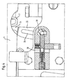
- the clip conveyor 1 as essential components, a drive unit 10, a feed or transport element 20, an adjustment 30 and a retainer 40 on.
- the drive unit 10 which has an eccentric drive element in the illustrated embodiment, is located below the horizontally extending and in a clip guide 4 guided clip strand 2.
- the eccentric is mounted on a rotatably mounted drive shaft 12.
- the eccentric is mounted rotatably and axially fixed so arranged that its eccentric one in the plane of the FIG. 1 describes running circle.
- the eccentric can be set in rotation, for example, by a belt or chain drive, not shown, which is driven by the main machine drive or by the main machine axis. It is also possible that the drive of the eccentric are driven by a likewise not shown hydraulic or pneumatic cylinder or by a turn not shown electric motor. It is usually made of stainless steel.
- the clip guide 4 is formed by a horizontally extending and downwardly open substantially U-shaped profile. In this, the clip strand 2 is held displaceably in the feed direction V and secured against slipping sideways (see. Fig. 1 ).
- the clip guide 4 has a pivot point, not shown, which allows it to be raised together with the clip strand 2 and lowered again when the feed element 20 passes through a feed step explained in more detail below.
- the substantially vertically arranged elongated and lever-like feed element 20 consists of an approximately cuboid flat material whose main plane of extension in the plane of the FIG. 1 lies.
- the feed element 20 is also preferably made of stainless steel. It has at its drive end 22 an eye over which it is axially fixed to the eccentric pin 14 and rotatably connected to the drive unit 10 about its longitudinal axis.
- the conveying end or the conveying tooth 24 of the advancing element 20 is formed by a likewise cuboidal flat material, which, however, is arranged perpendicular to the main extension plane of the advancing element 20.
- a slot 26 is incorporated, which runs centrally on the transport element 20 and in its longitudinal extent.
- the adjustment means 30 consists of a rotatably mounted in the clip lever shaft 32, at its upper end in the illustration, an adjustment member 34 is mounted, by means of which the shaft 32 can be rotated about its longitudinal axis.
- an eccentric 35 is formed on this. It has an axis-parallel to the shaft 32 extending eccentric pin 36 which is aligned in the direction of the feed element 20.
- latching devices in the form of radially arranged bores 38 are further provided, in which an unspecified, spring-loaded locking element 39 engages to fix the selected position of the adjuster 30 and secure against unintentional adjustment (see. Fig. 4 ).
- the adjusting device 30 is arranged in the region of the slot 26 of the advancing element 20 and substantially vertically above the drive unit 10.
- the axis of the shaft 32 of the adjusting device 30 extends horizontally in and perpendicular to the feed direction V.
- the advancing element 20 facing eccentric pin 36 engages the slot 26 and thus forms the pivot axis 36 for the transport element 20.
- the adjustment device 30 is also preferably made of stainless Made of steel.
- actuator 34 Since that in Fig. 2 shown actuator 34 experiences little mechanical stress, it may for example be made of aluminum and about have a correspondingly designed surface to further facilitate manual adjustment of the clip size. As continues in Fig. 2 can be seen, may be provided on the adjusting element 34 a the clip sizes corresponding label.
- the retaining device 40 for the clip strand 2 is formed in the illustrated embodiment, first by a on the die 5 next to the first pocket 5 a, which holds a clip to be closed clip 3 (1st clip of the clip strand), provided second pocket 5 b, which, as this out Fig. 2 can be seen, left of the shearing edge 6 of the die 5 is located. How to continue Fig. 2 can be removed, in this second pocket 5b of the first clip 3 immediately following second clip 3 is arranged. In order for the second clip 3 immediately following the first clip to remain arranged in the second pocket 5b of the die 5, the clip guide 4 continues to extend beyond this second clip 3, as does likewise Fig. 2 is apparent.
- the horizontally extending upper end plate of the clip guide 4 presses on the located in the second pocket 5b of the die 5 clip 3, so that the clip strand is not withdrawn against the feed direction V at Auseingingriffalter the feed element 20.
- the second pocket 5b has the same configuration as the first pocket 5a, ie, their bottom contour curve corresponds to that of a clip 3.
- the leaf spring previously used in the prior art is recognizable, which may optionally be provided in addition.
- the retaining device 40 according to the invention which, as already mentioned above, can be used independently of the adjusting device 30 in a generic clip conveyor, is no longer dependent on this leaf spring. Rather, the second pocket 5b of the die 5 and the clip guide 4 suffices.
- the drive unit 10 rotates in the with A in Fig. 1 marked direction in a clockwise direction about the axis of rotation of the shaft 12.
- the drive end 22 of the feed element 20 describes a in the plane of the Fig. 1 lying circle.
- the conveying end 24 of the advancing element 20 is disengaged from the clip strand 2.
- the feed element 20 is moved due to the guide by the pivot axis 36 in the slot 26 down and pivoted about the pivot axis 36.
- the conveying end 24 of the advancing element 20 upon rotation of the drive unit 10 in a clockwise direction, the conveying end 24 of the advancing element 20 describes an elliptical path in the counterclockwise direction. While the eccentric pin 14 describes the lower half of the circular path about the axis of the rotary shaft 12 of the drive unit 10 starting from the right, the conveying end 24 of the feed element 20 moves on the lower half of the elliptical path from left to right. It gets out of engagement with the clip strand 2 and moves according to the elliptical path down and back up again to intervene, offset by the length of the horizontally extending ellipse axis to the right, in the clip strand 2.
- the die 5 and an unrepresented stamp of the closing tools of the clip machines are moved together to close the inserted in the clip 3, not shown plait packaging wrapper material.
- the clip 3 is sheared off by the interaction of the shearing edge 6 of the die 5 and a corresponding shearing edge of the stamp from the clip strand 2 and pressed around the lying in the clip 3 plait packaging wrapper material, to close this.
- the retaining device 40 prevents the clip strand 2 from slipping backwards counter to the feed direction V by the support of the leg 5 of the clip strand 2 facing the die 5.
- the finished sausage product is transported out of the clip machine.
- the eccentric pin 14 of the drive unit 10 describes in the further course of the production process of a sausage product, the upper half of the circular path.
- the conveying end 24 of the advancing element 20, which is now again in engagement with the clip strand 2 moves on the upper half of the elliptical path of right to left.
- the clip strand 2 is raised together with the clip guide 4 and lowered back into the position shown.
- the clip strand 2 in the guide 4 is displaced to the left by the length of the horizontally extending ellipse axis or by one clip length, and the front clip 3 is moved over the shear edge 6 into the first pocket 5 a of the die 5 and the immediately following second clip 3 in the second pocket 5b of the die 5, which forms the retainer 40 together with the clip guide 4, promoted.
- a clip strand 2 was first inserted into the clip machine for the production process described above, and the adjusting element 34 was turned into the corresponding position corresponding to the size of the inserted clips. If, for example, the caliber of the sausage products to be produced is changed for a further production process, it is usually necessary to use clips of other sizes in addition to other closing tools. Such clips have not only a different leg length, but usually also a different width, so that an adjustment of the clip feed must be made.
- the actuator 34 has a classification corresponding to the selectable clip sizes.
- the desired clip size is adjusted by turning the actuator 34.
- the pivot axis 36 of the feed element 20 is moved on a circular path about the rotational axis of the shaft 32 of the adjusting device 30 (see. Fig. 1 ).
- the pivot axis 36 moves both horizontally and vertically.
- both the feed stroke and the point of engagement of the delivery end 24 of the feed element 20 change
- the horizontal adjustment component causes a shift of the engagement point of the conveying end 24 of the advancing element 20 in the clip strand 2 to the right or left.
- the conveying end 24 of the advancing element 20 describes an ellipse whose main axis also runs through this vertical imaginary line.
- On this line is the point of the highest vertical stroke of the clip strand 2.
- the point of engagement of the conveyor end 24 is in the clip strand 2 and at the same distance to the left of this line is the point at which the conveying end 24 of the advancing member 20 is disengaged from the clip strand 2.
- latching elements may be provided, which are designed in the illustrated embodiment as radially arranged bores 38 in the shaft 32 of the adjusting device 30, in which a spring-loaded locking element 39 engages.
- This securing element 39 is a substantially cylindrical pin which can engage against the tension of a spring 39 a in one of the radial bores 38 in order to prevent unintentional rotation of the shaft 32.
- the spring tension is chosen so that on the one hand prevents rotation of the shaft 32 by the movement of the feed element 20, on the other hand, however, allows an intentional adjustment by manual actuation of the actuating element 34.
- three radial bores are mounted on the shaft 32, for adjusting the clip size setting at three different clip sizes.
- any number of locking positions for the securing element 39 may be provided in order to achieve a corresponding adaptation of the clip size setting to different numbers of clip sizes.
- the invention does not refer to that in the Fig.1 and 2 illustrated embodiment is limited. It is conceivable, for example, for the advancing element 20 to essentially consist of a hollow profile in order, for example, to achieve a reduction in the moved mass, as a result of which vibrations in the clip machine can be reduced.
- the retainer 40 may also be designed as a piston / cylinder assembly, in which case instead of in the Fig. 1 and 2 shown second pocket 5b of the die 5 and the clip guide 4 of the piston is moved hydraulically or pneumatically in the appropriate position. Also can be used instead of hydraulic or pneumatic drives electric drive.
- pivot axis 36 can be adjusted by a linear guide.
- the horizontal and the vertical adjustment component can be weighted differently or one of both completely excluded.
- the locking elements can be designed so that they engage audibly and / or tactually, thereby an accurate adjustment of the desired clip size is facilitated. It can also be provided that the securing element 39 is designed so that it can be actuated from the outside, for example by an actuating element located on the machine. This allows a higher spring tension can be selected for locking and thus a safer locking can be achieved.
Description
Die vorliegende Erfindung betrifft eine Clipfördervorrichtung zum Fördern eines aus mehreren Clips bestehenden Clipstrangs in einer Clipmaschine, insbesondere einer Wurstclipmaschine, gemäß dem Oberbegriff des Anspruchs 1.The present invention relates to a clip conveying device for conveying a clip strand consisting of a plurality of clips in a clip machine, in particular a sausage clipper, according to the preamble of claim 1.
Insbesondere betrifft die Erfindung eine Clipfördervorrichtung zum Fördern eines aus mehreren Verschlussklammern bzw. Clips bestehenden Verschlussklammern- bzw. Clipstrangs in einer Clipmaschine, insbesondere einer Wurstclipmaschine, wobei die Clipfördervorrichtung eine Antriebseinheit und ein Vorschub-bzw. Transportelement aufweist. Das Vorschubelement ist mit seinem Antriebsende mit der Antriebseinheit gekoppelt. Dabei ist es von der Antriebseinheit in der Weise antreibbar, dass sein dem Antriebsende gegenüberliegendes Förderende eine elliptische Bahn beschreibt und zum schrittweisen Fördern des Clipstranges in Zwischenräume zwischen zwei Clips des Clipstrangs eingreift und diesen schrittweise in Vorschubrichtung fördert.In particular, the invention relates to a clip conveying device for conveying a closure clip or clip strand consisting of a plurality of closing clips or clips in a clip machine, in particular a sausage clipper, wherein the clip conveying device comprises a drive unit and a feed or feed mechanism. Has transport element. The feed element is coupled with its drive end to the drive unit. It is driven by the drive unit in such a way that its end opposite the drive end describes an elliptical path and engages the gradual conveying of the clip strand in spaces between two clips of the clip strand and this promotes stepwise in the feed direction.
In der Praxis ist es bekannt, dass beispielsweise bei der Herstellung von Wurstprodukten das Wurstbrät von einer Füllmaschine über ein Füllrohr einer Clipmaschine zugeführt wird. In der Clipmaschine wird das Füllgut in ein durch einen ersten Clip an dem ersten Wurstende einseitig verschlossenes, schlauchförmiges Verpackungshüllenmaterial abgefüllt und durch Setzen eines zweiten Clips an dem zweiten Wurstende verschlossen. Anschließend wird das Verpackungshüllenmaterial des so entstandenen Wurstprodukts von dem Vorrat des übrigen Verpackungshüllenmaterials abgetrennt und das fertiggestellte Wurstprodukt aus der Clipmaschine ausgetragen.In practice, it is known that, for example, in the production of sausage products, the sausage meat is fed from a filling machine via a filling tube of a clip machine. In the clipper, the contents in a by a first clip filled on the first sausage end unilaterally closed, tubular packaging casing material and closed by setting a second clip on the second sausage end. Subsequently, the packaging casing material of the resulting sausage product is separated from the supply of the remaining packaging casing material and discharged the finished sausage product from the clip machine.
Zum Setzen und Verschließen der Verschlussklammern oder des Clips besitzt die Clipmaschine üblicherweise ein erstes Verschließwerkzeug, die Matrize, und ein zweites Verschließwerkzeug, den Stempel. Diese sind zwischen der Mündungsöffnung des Füllrohrs und der Transporteinrichtung der Clipmaschine zum Austragen der fertiggestellten Wurstprodukte angeordnet. Dabei befindet sich üblicherweise die Matrize unterhalb des Förderweges der Wurstprodukte und der Stempel oberhalb dieses Förderweges. Nach dem Einlegen eines Clips in die Matrize und dem Einlegen eines gerafften füllgutfreien Zopfes an Verpackungshüllenmaterial in diesen Clip werden beide Verschließwerkzeuge so aufeinander zu bewegt, dass sie den zwischen sich befindlichen Clip zusammenpressen und dadurch das Verpackungshüllenmaterial verschließen.For setting and closing the closing clips or the clip, the clip machine usually has a first closing tool, the die, and a second closing tool, the punch. These are arranged between the mouth opening of the filling tube and the transport device of the clip machine for discharging the finished sausage products. In this case, usually the die is below the conveying path of the sausage products and the stamp above this conveying path. After inserting a clip into the die and inserting a shirred pigtail plait packaging bag material in this clip both Verschließwerkzeuge be moved towards each other so that they compress the clip between them and thereby seal the packaging casing material.
Mit der eingangs beschriebenen Clipmaschine werden typischerweise Clips verarbeitet, die aus einem geprägten Aluminiumdrahtstrang gefertigt werden. Hierzu sind die Clips U-förmig vorgebogen und hängen mittels an ihren Schenkelenden abgekröpften Stegen zusammen. Der so gebildete Clipstrang wird der Matrize durch eine Clipfördervorrichtung entlang einer Führungsbahn zugeführt, die in den Bereich des zugeordneten Verschließwerkzeugs mündet.With the clip machine described above typically clips are processed, which are made of an embossed aluminum wire strand. For this purpose, the clips are pre-bent in a U-shape and hang together by means of bent at their leg ends webs. The thus formed clip strand is fed to the die by a clip conveyor along a guideway, which opens into the region of the associated closing tool.
Beim Transport bzw. Vorschub eines Clipstrangs durch die in der Praxis bekannten Clipfördervorrichtungen wird der vorderste Clip bekanntermaßen von einem intermittierend eingreifenden Vorschubelement der Matrize zugeführt. Solange der vorderste Clip noch mit dem nachfolgenden Clipstrang verbunden ist, wird er von diesem stabil in der Matrize gehalten. Beim Verschließen wird zunächst die Matrize in ihre Verschließ- oder Hubendstellung gefahren. In dieser Stellung wird der vorderste Clip gegen den Zopf aus Verpackungshüllenmaterial gedrückt und ist zwischen diesem sowie der Matrize eingespannt.During transport or advancement of a clip strand through the clip conveying devices known in practice, the foremost clip is known to be fed by an intermittently engaging advancing element of the die. As long as the foremost clip is still connected to the subsequent strand of the clip, it is stably held by the latter in the die. When closing, the die is first moved to its closing or stroke end position. In this position, the foremost clip is pressed against the braid of packaging casing material and is clamped between this and the die.
Eine Clipmaschine der eingangs genannten Art ist aus der EP-Offentegungsschrift 1 736 412 bekannt. Die dort gezeigte Clipmaschine weist einen Verschließhebel mit einem ersten Verschließwerkzeug, der Matrize, auf, welches an dem Verschließhebel angeordnet und mit diesem schwenkbar ist. Ein zweites Verschließwerkzeug, der Stempel, ist entlang linearer Führungsmittel relativ zum ersten Verschließwerkzeug verfahrbar angeordnet. Die Verschließwerkzeuge sind zum Verschließen von Clips relativ zueinander zwischen einer Öffnungsstellung und einer Verschlussstellung bewegbar. Ein Clipstrang wird dem Verschließhebel entlang einer in der Nähe der Schwenkachse des Verschließhebels beginnenden Führungsbahn in Richtung der Matrize geführt. Als Antrieb für den Transport des Clipstrangs ist am vorderen Ende des Verschließhebels ein intermittierend an dem Clipstrang angreifendes Fördermittel in Form eines exzentrisch angetriebenen Hebels angeordnet. Das Fördermittel hebt den Clipstrang an seinem der Matrize nahen Ende an, zieht ihn in Richtung der Matrize nach und legt dabei den vordersten Clip des Clipstrangs in die Matrize ein.A clip machine of the type mentioned is known from EP-Offentegungsschrift 1 736 412. The clip machine shown there has a closing lever with a first closing tool, the die, which is arranged on the closing lever and pivotable with this. A second closing tool, the stamp, is arranged to be movable along linear guide means relative to the first closing tool. The closure tools are movable for closing clips relative to each other between an open position and a closed position. A clip strand is guided in the direction of the die along a guide track beginning near the pivot axis of the closing lever. As drive for the transport of the clip strand, an intermittently acting on the clip strand conveyor in the form of an eccentrically driven lever is arranged at the front end of Verschließhebels. The conveyor raises the clip strand at its end near the die, pulls it in the direction of the die, thereby inserting the foremost clip of the clip strand into the die.
Zeitversetzt, d.h. noch während die Matrize in dieser Stellung verharrt, bewegt sich der Stempel auf die Matrize zu. Unmittelbar vor dem Verschließen des Clips wird zunächst mittels einer an dem Stempel vorgesehenen Schereinrichtung der vorderste Clip von dem nachfolgenden Clipstrang abgetrennt. In diesem Moment ist der vorderste Clip frei und wird nur noch durch die Spannung des Zopfes gegen die Matrize angedrückt. Anschließend wird der Clip durch eine weitere Annäherung des Stempels an die Matrize plastisch verformt, bis sich die Verschließwerkzeuge bis auf die Klammerhöhe angenähert haben und der Clip um den Schlauchzopf herum verschlossen ist.Time delayed, i. while the die remains in this position, the die moves towards the die. Immediately before the closing of the clip, the first clip is first separated from the following clip strand by means of a shearing device provided on the stamp. At this moment, the front clip is free and is only pressed by the tension of the braid against the die. Subsequently, the clip is plastically deformed by a further approach of the punch to the die until the closing tools have approached to the clip height and the clip is closed around the Schlauchzopf around.
Solche bekannten Clipfördervorrichtungen haben üblicherweise einen fest eingestellten Vorschubhub, der der Clipgröße angepasst ist. Sollen Clips einer anderen Größe verarbeitet werden, beispielsweise bei Änderung des Kalibers der Wurstprodukte, ist es nötig, die Vorschublänge bzw. den Vorschubhub der neuen Clipgröße anzupassen.Such known clip conveyor usually have a fixed feed stroke, which is adapted to the clip size. If clips of a different size are to be processed, for example if the calorie of the sausage products changes, it is necessary to adjust the feed length or the feed stroke of the new clip size.
Dabei ist es in der Praxis bei den bekannten Clipfördervorrichtungen weiterhin bekannt, zum Erzeugen der intermittierenden Vorschubbewegung einen Exzenter zu verwenden. Hierdurch kann durch Verschiebung des Schwenkpunktes des Vorschubelementes eine Veränderung des Vorschubhubs bzw. der Vorschublänge erzielt werden. Da üblicherweise der Schwenkpunkt des Vorschubelements an der Matrizenauflage bzw. Matrizenhalterung befestigt ist, muss diese komplett gewechselt werden, wenn eine andere Clipgröße bearbeitet werden soll. Dies erfordert aber den Einsatz von Werkzeug sowie ein zumindest teilweises Zerlegen der Clipmaschine. Dies ist zeitaufwändig und damit kostenintensiv.It is also known in practice in the known clip conveyor devices to use an eccentric for generating the intermittent feed movement. As a result, a change in the feed stroke or the feed length can be achieved by shifting the pivot point of the feed element. Since usually the pivot point of the feed element is attached to the Matrizenauflage or die holder, it must be completely changed if another clip size is to be edited. However, this requires the use of tools and at least partial disassembly of the clip machine. This is time consuming and therefore costly.
Die in der Praxis bekannten Clipfördervorrichtungen weisen einen weiteren Nachteil auf. Der Clipstrang ist für einen Zeitraum zwischen dem Abtrennen des in der Matrize befindlichen Clips und dem erneuten Eingreifen des Vorschubelements in die folgende Lücke zwischen zwei Clips des Clipstrangs in Vorschubrichtung nicht arretiert. Steht der Clipstrang durch die Vorschubbewegung unter Zugspannung, kann er beim Abtrennen des vordersten Clips vom Clipstrang im Eingriffsbereich des Vorschubelements entgegen der Vorschubrichtung zurückgezogen werden, was einen gewünschten Eingriff erschwert oder verhindert.The known in practice clip conveyor devices have a further disadvantage. The clip strand is not locked for a period between the separation of the clip located in the die and the renewed engagement of the feed element in the following gap between two clips of the clip strand in the feed direction. If the clip strand is under tension due to the advancing movement, it can be withdrawn against the advancing direction when the foremost clip is separated from the clip strand in the engagement region of the advancing element, which impedes or prevents a desired engagement.
Aufgabe der vorliegenden Erfindung ist es eine Clipfördervorrichtung zum Fördern eines aus mehreren Clips bestehenden Clipstrangs in einer Clipmaschine der eingangs genannten Art bereitzustellen, die einfach gebaut ist und die eine einfache Einstellung der Vorschublänge bzw. des Vorschubhubs des Clipstrangs erlaubt.Object of the present invention is to provide a clip conveyor for conveying a clip consisting of several clips in a clip machine of the type mentioned above, which is simple and which allows easy adjustment of the feed length and the feed stroke of the clip strand.
Die vorstehende Aufgabe wird durch die Merkmale des Anspruchs 1 gelöst. In den sich daran anschließenden Ansprüchen 2 bis 10 finden sich vorteilhafte Ausgestaltungen hierzu.The above object is solved by the features of claim 1. In the
Zur Lösung der Aufgabe wird erfindungsgemäß eine Clipfördervorrichtung zum Fördern eines aus mehreren Clips bestehenden Clipstrangs in einer Clipmaschine, insbesondere einer Wurstclipmaschine, vorgeschlagen, die eine Antriebseinheit und ein Vorschubelement aufweist, das mit seinem Antriebsende mit der Antriebseinheit gekoppelt ist und von der Antriebseinheit in der Weise antreibbar ist, dass sein Förderende eine elliptische Bahn beschreibt und zum schrittweisen Fördern des Clipstranges in Zwischenräume zwischen zwei Clips des Clipstrangs eingreift und diesen schrittweise in Vorschubrichtung fördert.To achieve the object, a clip conveyor for conveying a clip consisting of several clips in a clip machine, in particular a sausage clipper, proposed according to the invention, which has a drive unit and a feed element, which is coupled with its drive end to the drive unit and the drive unit in the manner is drivable that its end conveyor describes an elliptical path and engages the gradual conveying of the clip strand in spaces between two clips of the clip strand and this promotes stepwise in the feed direction.
Bei der vorgeschlagenen Vorrichtung ist erfindungsgemäß weiterhin eine Einstelleinrichtung mit einer Schwenkachse vorgesehen, um die das Vorschubelement schwenkbar ist und die in ihrer Lageposition werkzeuglos in der Weise einstellbar ist, dass wenigstens eine der beiden Achsen, Haupt- oder Nebenachse, der von dem Förderende des Vorschubelements beschriebenen elliptischen Bahn veränderbar ist. Eine solche Einstellvorrichtung ermöglicht eine einfaches und schnelles Anpassen des Vorschubhubs des Vorschubelements an die jeweilige Clipgröße, ohne dass dabei Werkzeug eingesetzt werden muss und/oder dass die Clipmaschine zumindest teilweise zerlegt werden muss.In the proposed device according to the invention further comprising an adjusting device is provided with a pivot axis about which the feed element is pivotable and which is adjustable in its position without tools in such a way that at least one of the two axes, main or minor axis of the feed end of the feed element described elliptical path is changeable. Such an adjustment device allows a simple and quick adjustment of the feed stroke of the feed element to the respective clip size, without the need to use tools and / or that the clip machine must be at least partially disassembled.
In einer bevorzugten Ausbildung ist die Lageposition der Schwenkachse der Einstelleinrichtung durch einen Exzenter einstellbar. Die Schwenkachse ist somit auf einer Kreisbahn verstellbar, wodurch bei einer Änderung der Lageposition der Schwenkachse ein gleichzeitiges Verstellen des Vorschubhubs bzw. der Vorschublänge wie auch der Eingriffsposition des Förderendes des Vorschubelements erfolgt. Diese Verstellmöglichkeit ist vorteilhaft, da sich bei geänderter Clipgröße neben dem Vorschubhub auch der Eingriffspunkt am Clipstrang ändert.In a preferred embodiment, the position of the pivot axis of the adjusting device is adjustable by an eccentric. The pivot axis is thus adjustable on a circular path, whereby a change in the position position of the pivot axis, a simultaneous adjustment of the feed stroke or the feed length as well as the engagement position of the delivery end of the feed element takes place. This adjustment is advantageous because when changed Clip size next to the feed stroke and the engagement point on the clip strand changes.
Selbstverständlich ist es auch möglich, die Einstellbarkeit der Lageposition der Schwenkachse der Einstelleinrichtung durch andere Ausgestaltungen wie einer Linearführung zu realisieren. Eine solche Linearführung ist einfach zu herzustellen und durch die Wahl einer entsprechenden Form sehr zuverlässig. Weiterhin bietet sie bei entsprechender Ausrichtung hinsichtlich der Einstellbarkeit die gleichen Vorteile, wie die zuvor bei dem Exzenter genannten.Of course, it is also possible to realize the adjustability of the position position of the pivot axis of the adjustment by other configurations such as a linear guide. Such a linear guide is easy to manufacture and very reliable by choosing a suitable form. Furthermore, it offers the same advantages in terms of adjustability with the appropriate orientation, as those previously mentioned in the eccentric.
Die Lageposition der Schwenkachse der Einstelleinrichtung kann auf verschiedene Weise eingestellt werden. Geschieht dies in vorteilhafter Weise von außen durch ein Stellelement, so kann die Einstellung manuell erfolgen.The position of the pivot axis of the adjustment can be adjusted in various ways. If this is done in an advantageous manner from the outside by an actuator, so the adjustment can be done manually.
Das Vorschubelement darf nicht fest mit der Schwenkachse verbunden sein, sondern muss, um die gewünschte Funktion korrekt zu erfüllen, entlang der Schwenkachse verschiebbar geführt sein. In einer vorteilhaften Ausführung greift die Schwenkachse der Einstelleinrichtung in ein Langloch im Vorschubelement ein. Durch diese einfache und sichere Konstruktion wird die Führung des Vorschubelements sichergestellt.The feed element may not be firmly connected to the pivot axis, but must, in order to fulfill the desired function correctly, be slidably guided along the pivot axis. In an advantageous embodiment, the pivot axis of the adjusting device engages in a slot in the feed element. This simple and safe construction ensures the guidance of the feed element.
Die Antriebseinheit für das Vorschubelement kann durch verschiedene Antriebselemente gebildet sein. In einer besonders vorteilhaften Ausführung ist das Antriebselement ein Exzenter. Die gewünschte Ellipsenbahn des Förderendes des Vorschubelements lässt sich durch die Verwendung eines Exzenters besonders einfach erzeugen und in der gewünschten Weise verändern.The drive unit for the feed element can be formed by various drive elements. In a particularly advantageous embodiment, the drive element is an eccentric. The desired elliptical path of the conveying end of the feed element can be particularly easily generated by the use of an eccentric and change in the desired manner.
Dabei ist es weiterhin vorteilhaft, wenn die Welle des Antriebselements um eine nicht verschiebbare Achse rotiert. Bei der vorbeschriebenen Verwendung eines Exzenters rotiert der zugehörige Exzenterzapfen auf einer räumlich in Relation zur Schwenkachse der Einstelleinrichtung festgelegten Kreisbahn. So wird jeder Position der Schwenkachse der Einstelleinrichtung genau ein bestimmter Vorschubhub und ein zugehöriger Eingriffspunkt des Förderendes des Vorschubelements zugeordnet.It is also advantageous if the shaft of the drive element rotates about a non-displaceable axis. In the above-described use of an eccentric of the associated eccentric pin rotates on a fixed in relation to the pivot axis of the adjusting circular path. Thus, each position of the pivot axis of the adjustment is assigned exactly a certain feed stroke and an associated point of engagement of the delivery end of the feed element.
In einer weiteren vorteilhaften Ausführung der erfindungsgemäßen Vorrichtung ist die Achse des Antriebselements der Antriebseinheit zusätzlich so einstellbar, dass wenigstens eine der beiden Achsen, Haupt- oder Nebenachse, der von dem Förderende des Vorschubelements beschriebenen elliptischen Bahn veränderbar ist. Durch eine horizontale und/oder vertikale Verschiebbarkeit der Achse des Antriebselements der Antriebseinheit würde sich die Kreisbahn des Exzenterzapfens des Antriebselements entsprechend verschieben, wodurch eine weitere Einstellmöglichkeit zur Verstellung des Vorschubhubs und des Eingriffspunkts des Vorschubelements geschaffen würde.In a further advantageous embodiment of the device according to the invention, the axis of the drive element of the drive unit is additionally adjustable so that at least one of the two axes, main or minor axis, the elliptical path described by the conveying end of the advancing element is variable. By a horizontal and / or vertical displaceability of the axis of the drive element of the drive unit, the circular path of the eccentric pin of the drive element would move accordingly, creating a further adjustment for adjusting the feed stroke and the engagement point of the feed element would be created.
Durch den Vorschub des Clipstrangs können in diesem Zugspannungen auftreten. Beim Abtrennen des vordersten Clips kann der Clipstrang, da dieser üblicherweise nur durch den vordersten, in der Matrize befindlichen Clip gehalten ist, durch die vorgenannten Zugspannungen zumindest teilweise aus dem Eingriffbereich des Vorschubelements entgegen der Vorschubrichtung zurückgezogen werden, wodurch ein erneuter genauer Eingriff des Vorschubelements erschwert oder verhindert wird. Die weiterhin vorgesehene selbsttätig wirkende Rückhalteeinrichtung, die mit einem sich am vorderen Ende des Clipstrangs befindlichen Clip in Eingriff bringbar ist, verhindert wirkungsvoll ein Zurückrutschen des Clipstrangs, nachdem der in der Matrize liegende Clip vom Clipstrang abgetrennt wurde. Auf diese Weise wird durch die so erreichte immer gleiche Position des Clipstrangs der korrekte Eingriff des Vorschubelements in den Clipstrang gewährleistet. Es ist noch zu bemerken, dass die Rückhalteeinrichtung sowie die nachstehend noch näher erläuterten vorteilhaften Ausgestaltungen hiervon auch unabhängig von der vorstehend näher beschriebenen Einstelleinrichtung bei einer gattungsgemäßen Clipfördervorrichtung eingesetzt werden kann, da die Möglichkeit zum Einstellen der Clipfördervorrichtung auf verschiedene Clipgrößen unabhängig ist von dem Problem, den Clipstrang nach einem Förder- bzw. Vorschubschritt in seiner Position zu halten.The feed of the clip strand can occur in this tensile stresses. When separating the foremost clip of the clip strand, since this is usually held only by the foremost, located in the die clip, are retracted by the aforementioned tensile stresses at least partially from the engagement region of the feed element against the feed direction, whereby a more accurate engagement of the feed element difficult or prevented. The further provided self-acting retainer, which can be brought into engagement with a clip located at the front end of the clip strand, effectively prevents the clip strand from slipping back after the clip located in the die has been separated from the clip strand. In this way, the correct engagement of the feed element in the clip strand is ensured by the thus achieved always the same position of the clip strand. It should also be noted that the retaining device and the advantageous embodiments explained in more detail below can also be used independently of the setting device described in more detail in a generic clip conveying device, since the possibility of setting the clip conveying device to different clip sizes is independent of the problem. to hold the clip strand in its position after a conveying or advancing step.
Die Ausführung der Rückhalteeinrichtung kann auf verschiedene Weise realisiert werden. Eine besonders vorteilhafte Ausgestaltung wird dadurch erreicht, dass an der Matrize neben der den ersten Clip des Clipstrangs beim Verschließen fixierenden ersten Cliptasche eine Ausnehmung bzw. zweite Cliptasche vorgesehen ist, in der vorzugsweise der dem vordersten Clip unmittelbar nachfolgende Clip gehalten wird, wobei Kraftaufbringungsmittel zum Aufbringen einer Fixierkraft auf diesen Clip einwirken. Diese Kraftaufbringungsmittel können beispielsweise durch eine Clipführung gebildet sein, welche sich auf der Oberseite des Clipstranges befindet und die Haltekraft auf den in der zweiten Tasche der Matrize befindlichen Clip aufbringt.The embodiment of the retaining device can be realized in various ways. A particularly advantageous embodiment is achieved in that a recess or second clip pocket is provided on the die next to the first clip of the clip strand when closing fixing the first clip pocket, preferably in the immediately following the foremost clip Clip is held, wherein force applying means for applying a fixing force acting on this clip. These force application means can be formed for example by a clip guide which is located on the upper side of the clip line and applies the holding force to the clip located in the second pocket of the die.
In einer weiteren vorteilhaften Ausführung der erfindungsgemäßen Vorrichtung ist die Rückhalteeinrichtung durch einen Haken gebildet, der z.B. parallel neben oder unterhalb des Clipstrangs angeordnet sein kann. Dieser entgegen der Vorschubrichtung ausgerichtete Haken könnte beispielsweise durch die vertikale Hubbewegung des Clipstrangs beim Vorschub außer Eingriff mit dem Clipstrang gebracht werden und beim Absenken des Clipstrangs nach erfolgtem Vorschub wieder in diesen eingreifen. Durch einen solchen Haken wird der Clipstrang sicher fixiert und ein Zurückrutschen entgegen der Förderrichtung nach Abtrennen des in der Matrize befindlichen Clips verhindert.In a further advantageous embodiment of the device according to the invention, the retaining device is formed by a hook, which, e.g. can be arranged parallel to or below the clip strand. This against the feed direction aligned hooks could be brought out of engagement with the clip strand, for example, by the vertical lifting movement of the clip strand during the feed and engage in the lowering of the clip strand after a successful feed back into this. By such a hook, the clip strand is securely fixed and prevented from slipping back against the conveying direction after separation of the clip located in the die.
Die Rückhalteeinrichtung kann ebenfalls durch einen hydraulischen oder pneumatischen Zylinder gebildet sein.The retaining device may also be formed by a hydraulic or pneumatic cylinder.
Weitere vorteilhafte Ausgestaltungen sowie ein Ausführungsbeispiel der Erfindung werden nachstehend im Zusammenhang mit den beigefügten Zeichnungsfiguren näher erläutert. Die bei der Beschreibung des Ausführungsbeispiels verwendeten Begriffe "oben", "unten", "links" und "rechts" beziehen sich auf die Zeichnungsfiguren in einer Ausrichtung mit normal lesbaren Bezugszeichen und Figurenbezeichnungen.Further advantageous embodiments and an embodiment of the invention will be explained in more detail below in connection with the accompanying drawing figures. The terms "top", "bottom", "left" and "right" used in the description of the embodiment refer to the drawing figures in an orientation with normally readable reference numerals and figure names.
Es zeigen:
- Fig. 1
- eine Seitenansicht von rechts des prinzipiellen Aufbaus der erfindungsgemäßen Clipfördervorrichtung in einer Clipmaschine;
- Fig. 2
- eine Seitenansicht von links auf die erfindungsgemäße Clipfördervorrichtung;
- Fig. 3
- eine horizontale Schnittdarstellung der erfindungsgemäßen Clipfördervorrichtung; und
- Fig. 4
- eine vertikale Schnittdarstellung der erfindungsgemäßen Clipfördervorrichtung.
- Fig. 1
- a side view from the right of the basic structure of the clip conveying device according to the invention in a clip machine;
- Fig. 2
- a side view from the left on the inventive clip conveyor device;
- Fig. 3
- a horizontal sectional view of the clip conveying device according to the invention; and
- Fig. 4
- a vertical sectional view of the clip conveying device according to the invention.
Das nachstehend beschriebene Ausführungsbeispiel einer erfindungsgemäßen Clipfördervorrichtung kommt bei beispielsweise Wurstclipmaschinen der eingangs genannte Art zum Einsatz. Wie in
Die Antriebseinheit 10, die im gestellten Ausführungsbeispiel als Antriebselement einen Exzenter aufweist, befindet sich unterhalb des waagerecht verlaufenden und in einer Clipführung 4 geführten Clipstrangs 2. Der Exzenter ist auf einer drehbar gelagerten Antriebswelle 12 montiert. Der Exzenter ist dreh- und axialfest montiert so angeordnet, dass sein Exzenterzapfen einen in der Ebene der
Die Clipführung 4 ist durch ein waagerecht verlaufendes und nach unten offenes im Wesentlichen U-förmiges Profil gebildet. In diesem wird der Clipstrang 2 in Vorschubrichtung V verschiebbar gehalten und gegen seitliches Verrutschen gesichert (vgl.
Das im wesentlichen vertikal angeordnete langgestreckte und hebelartige Vorschubelement 20 besteht aus einem annähernd quaderförmigen Flachmaterial, dessen Haupterstreckungsebene in der Ebene der
Wie in
Die Einstelleinrichtung 30 ist im Bereich des Langlochs 26 des Vorschubelements 20 und im Wesentlichen senkrecht über der Antriebseinheit 10 angeordnet. Die Achse der Welle 32 der Einstelleinrichtung 30 verläuft horizontal in sowie senkrecht zur Vorschubrichtung V. Der zum Vorschubelement 20 weisende exzentrischer Zapfen 36 greift in das Langloch 26 ein und bildet so die Schwenkachse 36 für das Transportelement 20. Die Einstelleinrichtung 30 ist ebenfalls vorzugsweise aus rostfreiem Stahl hergestellt.The adjusting
Da das in
Die Rückhalteeinrichtung 40 für den Clipstrang 2 wird im dargestellten Ausführungsbeispiel zunächst durch eine an der Matrize 5 neben deren ersten Tasche 5a, welche einen zu verschließenden Clip 3 (1. Clip des Clipstrangs) hält, vorgesehenen zweiten Tasche 5b gebildet, die sich, wie dies aus
Der Bewegungsablauf der erfindungsgemäßen Vorrichtung wird im folgenden anhand des Vorschubs eines Clips ausgehend vom in
Im weiteren Verlauf des Herstellungsprozesses beispielsweise eines Wurstprodukts rotiert die Antriebseinheit 10 in der mit A in
Zeitgleich mit der zuvor beschriebenen Bewegung des Vorschubelements 20 werden die Matrize 5 und ein nicht dargestellter Stempel der Schließwerkzeuge der Clipmaschinen zusammengefahren, um den im Clip 3 eingelegten, nicht dargestellten Zopf aus Verpackungshüllenmaterial zu verschließen. Beim Zusammenfahren von Matrize 5 und des nicht dargestellten Stempels wird der Clip 3 durch das Zusammenwirken der Scherkante 6 der Matrize 5 und einer entsprechenden Scherkante des Stempels vom Clipstrang 2 abgeschert und um den in dem Clip 3 liegenden Zopf aus Verpackungshüllenmaterial zusammengepresst, um diesen zu verschließen. Dabei verhindert die Rückhalteeinrichtung 40 ein Zurückrutschen des Clipstrangs 2 entgegen der Vorschubrichtung V durch das Abstützen des zur Matrize 5 weisenden Schenkels des vordern Clips 3 des Clipstrangs 2. Das fertig verschlossene Wurstprodukt wird aus der Clipmaschine transportiert.Simultaneously with the previously described movement of the advancing
Der Exzenterzapfen 14 der Antriebseinheit 10 beschreibt im weiteren Verlauf des Herstellungsprozesses eines Wurstprodukts die obere Hälfte der Kreisbahn. Nach dem Überschreiten der durch die Achse der Drehwelle 12 gedachten, waagerecht verlaufenden Linie links dieser Achse der Antriebseinheit 10, bewegt sich das Förderende 24 des Vorschubelements 20, das jetzt wieder in Eingriff mit dem Clipstrang 2 steht, auf der oberen Hälfte der elliptischen Bahn von rechts nach links. Dabei wird der Clipstrang 2 zusammen mit der Clipführung 4 angehoben und wieder in die dargestellte Position abgesenkt. Während des Hebens und Senkens der Clipführung 4 wird der Clipstrang 2 in der Führung 4 um die Länge der waagerecht verlaufenden Ellipsenachse bzw. um eine Cliplänge nach links verschoben und der vordere Clip 3 wird über die Scherkante 6 hinweg in die erste Tasche 5a der Matrize 5 und der sich unmittelbar daran anschließende zweite Clip 3 in die zweite Tasche 5b der Matrize 5, die zusammen mit der Clipführung 4 die Rückhalteeinrichtung 40 bildet, gefördert.The
Die in
Bezüglich der Clipgrößeneinstellung wurde für den zuvor beschriebenen Herstellungsprozess zunächst ein Clipstrang 2 in die Clipmaschine eingelegt und das Stellelement 34 in die entsprechende Position, die der Größe der eingelegten Clips entspricht, gedreht. Wird für einen weiteren Herstellungsprozess beispielsweise das Kaliber der herzustellenden Wurstprodukte geändert, ist es meist notwendig, neben anderen Verschließwerkzeugen auch Clips anderer Größe zu verwenden. Solche Clips haben nicht nur eine andere Schenkellänge, sondern meist auch eine andere Breite, sodass eine Anpassung des Clipvorschubs erfolgen muss.With regard to the clip size setting, a
Diese Anpassung erfolgt wiederum über das manuelle Betätigen des in
Durch das Verstellen der Schwenkachse 36 ändern sich sowohl der Vorschubhub als auch der Eingriffspunkt des Förderendes 24 des Vorschubelements 20By adjusting the
Eine vertikale Verschiebung des Schwenkachse 36 nach unten vergrößert die obere Hebellänge des Vorschubelements 20 und die untere, antriebsseitige Hebellänge verkürzt sich entsprechend. Dadurch vergrößert sich der Vorschubhub des Förderendes 24 des Vorschubelements 20. Eine Verschiebung der Schwenkachse 36 nach oben verkürzt den oberen Teilhebel des Vorschubelements 20 und verlängert den unteren Teilhebel, wodurch sich der Vorschubhub des Vorschubelements 20 verringert.A vertical displacement of the
Die horizontale Verstellkomponente bewirkt eine Verschiebung des Eingriffspunktes des Förderendes 24 des Vorschubelements 20 in den Clipstrang 2 nach rechts bzw. links.The horizontal adjustment component causes a shift of the engagement point of the conveying
Befindet sich die Schwenkachse 36 der Einstelleinrichtung 30 auf einer gedachten senkrechten Linie, die durch die Achse 12 der Antriebseinheit 10 verläuft, beschreibt das Förderende 24 des Vorschubelements 20 eine Ellipse, deren Hauptachse ebenfalls durch diese senkrechte gedachte Linie verläuft. Auf dieser Linie liegt der Punkt des höchsten vertikalen Hubs des Clipstrangs 2. Rechts dieser Linie, entsprechender
Wird die Schwenkachse 36 der Einstelleinrichtung 30 horizontal nach rechts verschoben, verschiebt sich ebenfalls die elliptische Bahn, die das Förderende 24 beschreibt, nach rechts. Damit verschieben sich auch der Eingriffspunkt des Förderendes 24 in den Clipstrang 2 und der Punkt, an den das Förderende 24 des Vorschubelements 20 außer Eingriff mit dem Clipstrang 2 gelangt, entsprechend nach rechts.If the
Bei einer Verschiebung der Schwenkachse 36 der Einstelleinrichtung 30 horizontal nach links, tritt die gleiche Verschiebung der elliptischen Bahn und damit der zuvor beschriebenen Eingriffspunkte des Förderendes 24 in den Clipstrang 2 nach links ein.With a displacement of the
Bei einer Bewegung der Schwenkachse 36 auf einer Kreisbahn, entsprechend dem gezeigten Ausführungsbeispiel, verschiebt sich diese aber immer gleichzeitig horizontal und vertikal. Durch das Zusammenwirken beider Verstellkomponenten wird zusätzlich eine Änderung der Hubhöhe des Clipstrangs 2 und der Clipführung 4 erreicht.In a movement of the
Um ein ungewolltes Verstellen der Einstelleinrichtung 30 zu verhindern, können Rastelemente vorgesehen sein, die im dargestellten Ausführungsbeispiel als radial angeordnete Bohrungen 38 in der Welle 32 der Einstelleinrichtung 30 ausgeführt sind, in die ein federbelastetes Sicherungselement 39 eingreift. Dieses Sicherungselement 39 ist ein im Wesentlichen zylindrischer Stift, der gegen die Spannung einer Feder 39a in eine der radialen Bohrungen 38 eingreifen kann, um ein ungewolltes Verdrehen der Welle 32 zu verhindern. Die Federspannung ist dabei so gewählt, dass sie einerseits ein Verdrehen der Welle 32 durch die Bewegung des Vorschubelements 20 verhindert, andererseits aber ein beabsichtigtes Verstellen durch manuelles Betätigen des Stellelements 34 erlaubt.In order to prevent unintentional adjustment of the adjusting
Im dargestellten Ausführungsbeispiel sind drei radiale Bohrungen an der Welle 32 angebracht, zur Anpassung der Clipgrößeneinstellung an drei unterschiedlichen Clipgrößen. Es können selbstverständlich beliebig viele Rastpositionen für das Sicherungselement 39 vorgesehen sein, um eine entsprechende Anpassung der Clipgrößeneinstellung an unterschiedlich viele Clipgrößen zu erreichen.In the illustrated embodiment, three radial bores are mounted on the
Abschließend ist noch zu bemerken, dass die Erfindung nicht auf das in den
Die Rückhalteeinrichtung 40 kann auch als Kolben-/Zylinderanordnung gestaltet sein, wobei dann anstelle der in den
Ebenso kann die Schwenkachse 36 durch eine Linearführung verstellbar sein. Durch eine entsprechende Anordnung der Linearführung können dann die horizontale und die vertikale Verstellkomponente verschieden gewichtet oder eine von beiden ganz ausgeschlossen werden.Likewise, the
Es ist ebenfalls möglich, das Fixieren des Clipstranges 2 nicht ausschließlich durch die Rückhalteeinrichtung 40 zu realisieren.It is also possible to realize the fixing of the
Die Rastelemente können so gestaltet, dass sie hör- und/oder fühlbar einrasten, dadurch wird eine genaue Einstellung der gewünschten Clipgröße erleichtert. Es kann ebenfalls vorgesehen sein, dass das Sicherungselement 39 so gestaltet ist, dass es von außen betätigbar ist, beispielsweise durch ein an der Maschine befindliches Betätigungselement. Dadurch kann eine höhere Federspannung zur Arretierung gewählt werden und damit eine sicherere Arretierung erreicht werden.The locking elements can be designed so that they engage audibly and / or tactually, thereby an accurate adjustment of the desired clip size is facilitated. It can also be provided that the securing
- 11
- ClipfördervorrichtungClip conveyor
- 22
- Clipstrangline of clips
- 33
- Clipclip
- 44
- Clipführungclip leadership
- 55
- Matrizedie
- 5a5a
- 1.Tasche1.Tasche
- 5b5b
- 2. Tasche2nd bag
- 66
- Scherkanteshearing edge
- 1010
- Antriebseinheitdrive unit
- 1212
- Achse der AntriebseinheitAxis of the drive unit
- 1414
- Exzenterzapfeneccentric
- 2020
- Vorschubelementfeed element
- 2222
- Antriebsendedrive end
- 2424
- Förderendedelivery end
- 2626
- LanglochLong hole
- 3030
- Einstelleinrichtungadjustment
- 3232
- Welle der EinstelleinrichtungShaft of the adjusting device
- 3434
- Stellelementactuator
- 3636
- Schwenkachseswivel axis
- 3838
- Bohrungendrilling
- 3939
- Sicherungselementfuse element
- 39a39a
- Federfeather
- 4040
- RückhalteeinrichtungRestraint
- AA
- Antriebsrichtungdriving direction
- VV
- Vorschubrichtungfeed direction
Claims (10)
- Clip conveyor apparatus for conveying a clip line (2) comprising a plurality of clips in a clipping machine, in particular a sausage clipping machine, comprising a drive unit (10) and an transport element (20) which is coupled with its drive end (22) to the drive unit (10) and is drivable by the drive unit (10) in such a way that its conveyor end (24) describes an elliptical path and engages into intermediate spaces between two clips of the clip line (2) for stepwise conveyance of the clip line (2) and conveys same stepwise in the advance direction (V),
characterized in that there is provided an adjusting device (30) having a pivot axis (36) about which the transport element (20) is pivotable and which is adjustable in its position without a tool in such a way that at least one of the axes of the elliptical path described by the conveyor end (24) is variable. - The clip conveyor apparatus of claim 1,
characterized in that the position of the pivot axis (36) of the adjusting device (30) is adjusted by an eccentric. - The clip conveyor apparatus of claim 1,
characterized in that the position of the pivot axis (36) of the adjusting device (30) is adjusted by a linear guide. - The clip conveyor apparatus according to one of the claims 1 to 3,
characterized in that the position of the pivot axis (36) of the adjusting device (30) is adjusted by an adjusting element (34) from the exterior. - The clip conveyor apparatus according to one of the claims 1 to 4,
characterized in that the pivot axis (36) of the adjusting device (30) engages into a slot (26) in the transport element (20). - The clip conveyor apparatus according to one of the claims 1 to 5,
characterized in that the drive unit (10) includes at least one eccentric. - The clip conveyor apparatus according to one of the claims 1 to 6,
characterized in that the drive unit (10) rotates about a fixed axis (12). - The clip conveyor apparatus according to one of the claims 1 to 7,
characterized in that the axis (12) of the drive unit (10) is movable to vary at least one of the axes of the elliptical path described by the conveyor end (24) of the transport element (20). - The clip conveyor apparatus according to one of the claims 1 to 8,
characterized in that there is provided an automatically acting retaining device (40) capable of being brought into engagement with a clip (3) disposed at the front end of the clip line (2). - The clip conveyor apparatus of claim 9,
characterized in that the retaining device (40) is formed by a recess (5b) provided on a die (5) and by a means for applying a force which applies a pressure force acting substantially perpendicularly to the advance direction (V) on the clip line.
Applications Claiming Priority (1)
| Application Number | Priority Date | Filing Date | Title |
|---|---|---|---|
| DE102007012778A DE102007012778B4 (en) | 2007-03-16 | 2007-03-16 | Adjustable clip feed |
Publications (2)
| Publication Number | Publication Date |
|---|---|
| EP1969946A1 EP1969946A1 (en) | 2008-09-17 |
| EP1969946B1 true EP1969946B1 (en) | 2011-01-26 |
Family
ID=39577900
Family Applications (1)
| Application Number | Title | Priority Date | Filing Date |
|---|---|---|---|
| EP08004493A Active EP1969946B1 (en) | 2007-03-16 | 2008-03-11 | Adjustable clip feeder |
Country Status (6)
| Country | Link |
|---|---|
| US (1) | US7926689B2 (en) |
| EP (1) | EP1969946B1 (en) |
| BR (1) | BRPI0801513B1 (en) |
| DE (2) | DE102007012778B4 (en) |
| ES (1) | ES2356696T3 (en) |
| RU (1) | RU2399273C2 (en) |
Families Citing this family (4)
| Publication number | Priority date | Publication date | Assignee | Title |
|---|---|---|---|---|
| EP2353393B1 (en) * | 2010-02-10 | 2016-04-20 | Poly-clip System GmbH & Co. KG | Manually operable clipping-machine |
| EP2572585B1 (en) * | 2011-09-26 | 2016-08-24 | Poly-clip System GmbH & Co. KG | Transportation device with star wheels |
| DE202012004217U1 (en) * | 2012-04-27 | 2013-07-30 | Tipper Tie Technopack Gmbh | Feed device for clip machine |
| CN112167303A (en) * | 2020-10-19 | 2021-01-05 | 石家庄睿普雷健康科技有限公司 | Food packaging punched-card machine |
Family Cites Families (20)
| Publication number | Priority date | Publication date | Assignee | Title |
|---|---|---|---|---|
| US2233839A (en) * | 1938-06-10 | 1941-03-04 | Heurtier Antoine | Moving picture projecting machine |
| US2404875A (en) * | 1944-02-07 | 1946-07-30 | George H Worrall | Kinetograph movement |
| US2420444A (en) * | 1944-08-29 | 1947-05-13 | Vry Corp De | Intermittent mechanism |
| US2506649A (en) * | 1947-02-08 | 1950-05-09 | Arthur E Reeves | Film feed mechanism |
| FR1190749A (en) * | 1957-01-16 | 1959-10-14 | Werkzeug Und Metallwarenfabrik | Clip for airtight sealing of bags and device for applying said clips |
| FR1414569A (en) * | 1964-11-24 | 1965-10-15 | Method and device for continuously closing sausages | |
| US3612371A (en) * | 1968-01-20 | 1971-10-12 | Nippon Kogaku Kk | Film transmitting device of miniature movie camera |
| CH481393A (en) * | 1968-09-27 | 1969-11-15 | Paillard Sa | Intermittent drive mechanism of a motion picture film |
| FR2123667A5 (en) * | 1971-01-27 | 1972-09-15 | Eclair Int | |
| US4257328A (en) * | 1979-05-18 | 1981-03-24 | Gavit Stephan E | Strip label printer |
| AT366828B (en) * | 1980-01-04 | 1982-05-10 | Moviecam Kinematograph | GRIPPERWERK FOR A FILM RECORDING CAMERA |
| US4357082A (en) * | 1980-12-29 | 1982-11-02 | Amesbury Maurice G | High speed film advancement mechanism and system therefor |
| US4534630A (en) * | 1984-01-31 | 1985-08-13 | Imax Systems Corporation | Wide film transport and register movement |
| US4896960A (en) * | 1988-10-13 | 1990-01-30 | Williamson Geoffry H | High speed transport for large film formats |
| DE10131807C1 (en) | 2001-06-30 | 2002-11-07 | Poly Clip System Gmbh & Co Kg | Sausage stuffing machine has plates and male and female locking components for clips pivoted on cranks and guided by guide which can swivel about axis of sausage casing |
| CH698066B1 (en) * | 2002-12-11 | 2009-05-15 | Tipper Tie Alpina Ag | A closing arrangement for locking clips. |
| DE20314562U1 (en) * | 2003-09-19 | 2003-12-04 | Poly-Clip System Gmbh & Co Kg | Clip machine drive |
| DE102004015892B4 (en) * | 2004-03-31 | 2006-02-09 | Poly-Clip System Gmbh & Co. Kg | Closing machine drive with adjustable articulation point |
| DE102005029227B4 (en) | 2005-06-23 | 2007-11-08 | Poly-Clip System Gmbh & Co. Kg | clipping machine |
| DE202005021188U1 (en) * | 2005-07-18 | 2007-04-19 | Poly-Clip System Gmbh & Co. Kg | Control system for clip machine especially for securing sections of sausage type string has type identification tag on the clip magazine read by monitoring system |
-
2007
- 2007-03-16 DE DE102007012778A patent/DE102007012778B4/en not_active Expired - Fee Related
-
2008
- 2008-03-11 ES ES08004493T patent/ES2356696T3/en active Active
- 2008-03-11 EP EP08004493A patent/EP1969946B1/en active Active
- 2008-03-11 DE DE502008002438T patent/DE502008002438D1/en active Active
- 2008-03-14 US US12/048,643 patent/US7926689B2/en active Active
- 2008-03-14 RU RU2008110021/13A patent/RU2399273C2/en active
- 2008-03-17 BR BRPI0801513-9A patent/BRPI0801513B1/en active IP Right Grant
Also Published As
| Publication number | Publication date |
|---|---|
| BRPI0801513B1 (en) | 2017-06-20 |
| RU2008110021A (en) | 2009-09-20 |
| US7926689B2 (en) | 2011-04-19 |
| ES2356696T3 (en) | 2011-04-12 |
| DE102007012778A1 (en) | 2008-09-18 |
| EP1969946A1 (en) | 2008-09-17 |
| RU2399273C2 (en) | 2010-09-20 |
| DE102007012778B4 (en) | 2010-06-24 |
| DE502008002438D1 (en) | 2011-03-10 |
| BRPI0801513A2 (en) | 2008-12-16 |
| US20080223694A1 (en) | 2008-09-18 |
Similar Documents
| Publication | Publication Date | Title |
|---|---|---|
| EP1736412B2 (en) | Clipping machine | |
| EP1967073B1 (en) | Automatic spreading adjustment | |
| EP1844659B1 (en) | Direct connection of sausage clip and sausage handling device | |
| EP1886573B1 (en) | Clipping machine | |
| DE1461915B2 (en) | Device for the production of square packs | |
| EP1969945B1 (en) | Method and device for controlled closing of at least one clip around a braided section devoid of filling material between two filling material sections in a wrapper | |
| EP0399322A3 (en) | Stitching device | |
| EP1969946B1 (en) | Adjustable clip feeder | |
| DE2628322C2 (en) | ||
| EP0712365B1 (en) | Device for closing a plastic clip in two parts | |
| EP2225948B1 (en) | Feed device for suspension elements | |
| EP2186415B1 (en) | Displacement component for a clip machine | |
| EP1926596A1 (en) | Device and method for feeding at least one material web or web strand into a folding device | |
| EP2103221B1 (en) | Screw conveyor sections | |
| EP2335486A2 (en) | Closing device for forming sausage-shaped packages | |
| DE102011100597B4 (en) | Manually height and tilt adjustable outlet bowl | |
| DE102004022716B4 (en) | Device for producing filled, sealed tubular bag packages | |
| EP1348571B1 (en) | Devie for binding flat, stacked elements | |
| EP1312264B1 (en) | Length measuring unit with clipping machine | |
| WO1987007239A1 (en) | Process for sealing tube-like packages, in particular sausage skins, by u-shaped closure clamps, and storage vessel and device therefor | |
| DE102017100511B4 (en) | Device and method for producing double-screw pastry blanks from P-shaped or U-shaped dough blanks designed as dough strands | |
| CH583641A5 (en) | Wire clip-forming unit for tying off tubular packages - which has punch in sliding guide and anvil for bending wire lengths | |
| EP1617726B1 (en) | Elliptical synchronous belt drive | |
| DE2037881A1 (en) | Packing machine | |
| DE20319755U1 (en) | Machine for stuffing, tying-off and sealing sausage skins has drive for units used in tying off and fitting clips which operates at lower speed during clip fitting than tying off |
Legal Events
| Date | Code | Title | Description |
|---|---|---|---|
| PUAI | Public reference made under article 153(3) epc to a published international application that has entered the european phase |
Free format text: ORIGINAL CODE: 0009012 |
|
| 17P | Request for examination filed |
Effective date: 20080326 |
|
| AK | Designated contracting states |
Kind code of ref document: A1 Designated state(s): AT BE BG CH CY CZ DE DK EE ES FI FR GB GR HR HU IE IS IT LI LT LU LV MC MT NL NO PL PT RO SE SI SK TR |
|
| AX | Request for extension of the european patent |
Extension state: AL BA MK RS |
|
| 17Q | First examination report despatched |
Effective date: 20090415 |
|
| AKX | Designation fees paid |
Designated state(s): CH DE ES IT LI |
|
| GRAP | Despatch of communication of intention to grant a patent |
Free format text: ORIGINAL CODE: EPIDOSNIGR1 |
|
| GRAS | Grant fee paid |
Free format text: ORIGINAL CODE: EPIDOSNIGR3 |
|
| GRAA | (expected) grant |
Free format text: ORIGINAL CODE: 0009210 |
|
| AK | Designated contracting states |
Kind code of ref document: B1 Designated state(s): CH DE ES IT LI |
|
| REG | Reference to a national code |
Ref country code: CH Ref legal event code: EP |
|
| REF | Corresponds to: |
Ref document number: 502008002438 Country of ref document: DE Date of ref document: 20110310 Kind code of ref document: P |
|
| REG | Reference to a national code |
Ref country code: DE Ref legal event code: R096 Ref document number: 502008002438 Country of ref document: DE Effective date: 20110310 |
|
| REG | Reference to a national code |
Ref country code: ES Ref legal event code: FG2A Ref document number: 2356696 Country of ref document: ES Kind code of ref document: T3 Effective date: 20110412 |
|
| REG | Reference to a national code |
Ref country code: CH Ref legal event code: NV Representative=s name: ZIMMERLI, WAGNER & PARTNER AG |
|
| PLBE | No opposition filed within time limit |
Free format text: ORIGINAL CODE: 0009261 |
|
| STAA | Information on the status of an ep patent application or granted ep patent |
Free format text: STATUS: NO OPPOSITION FILED WITHIN TIME LIMIT |
|
| 26N | No opposition filed |
Effective date: 20111027 |
|
| REG | Reference to a national code |
Ref country code: DE Ref legal event code: R097 Ref document number: 502008002438 Country of ref document: DE Effective date: 20111027 |
|
| REG | Reference to a national code |
Ref country code: CH Ref legal event code: PFA Owner name: POLY-CLIP SYSTEM GMBH & CO. KG Free format text: POLY-CLIP SYSTEM GMBH & CO. KG#WESTERBACHSTRASSE 45#60489 FRANKFURT AM MAIN (DE) -TRANSFER TO- POLY-CLIP SYSTEM GMBH & CO. KG#NIEDECKERSTRASSE 1#65795 HATTERSHEIM (DE) |
|
| REG | Reference to a national code |
Ref country code: DE Ref legal event code: R082 Ref document number: 502008002438 Country of ref document: DE Representative=s name: EISENFUEHR, SPEISER & PARTNER, DE |
|
| REG | Reference to a national code |
Ref country code: DE Ref legal event code: R081 Ref document number: 502008002438 Country of ref document: DE Owner name: POLY-CLIP SYSTEM GMBH & CO. KG, DE Free format text: FORMER OWNER: POLY-CLIP SYSTEM GMBH & CO KG, 60489 FRANKFURT, DE Effective date: 20130827 Ref country code: DE Ref legal event code: R082 Ref document number: 502008002438 Country of ref document: DE Representative=s name: EISENFUEHR SPEISER PATENTANWAELTE RECHTSANWAEL, DE Effective date: 20130827 |
|
| REG | Reference to a national code |
Ref country code: CH Ref legal event code: NV Representative=s name: WAGNER PATENT AG, CH |
|
| P01 | Opt-out of the competence of the unified patent court (upc) registered |
Effective date: 20230519 |
|
| PGFP | Annual fee paid to national office [announced via postgrant information from national office to epo] |
Ref country code: IT Payment date: 20230331 Year of fee payment: 16 Ref country code: ES Payment date: 20230414 Year of fee payment: 16 Ref country code: DE Payment date: 20230405 Year of fee payment: 16 Ref country code: CH Payment date: 20230402 Year of fee payment: 16 |