EP1726324B1 - Medicament container with same side airflow inlet and outlet - Google Patents
Medicament container with same side airflow inlet and outlet Download PDFInfo
- Publication number
- EP1726324B1 EP1726324B1 EP06016891A EP06016891A EP1726324B1 EP 1726324 B1 EP1726324 B1 EP 1726324B1 EP 06016891 A EP06016891 A EP 06016891A EP 06016891 A EP06016891 A EP 06016891A EP 1726324 B1 EP1726324 B1 EP 1726324B1
- Authority
- EP
- European Patent Office
- Prior art keywords
- medicament
- medicament container
- receptacle
- opening
- layer
- Prior art date
- Legal status (The legal status is an assumption and is not a legal conclusion. Google has not performed a legal analysis and makes no representation as to the accuracy of the status listed.)
- Expired - Lifetime
Links
Images


Classifications
-
- A—HUMAN NECESSITIES
- A61—MEDICAL OR VETERINARY SCIENCE; HYGIENE
- A61M—DEVICES FOR INTRODUCING MEDIA INTO, OR ONTO, THE BODY; DEVICES FOR TRANSDUCING BODY MEDIA OR FOR TAKING MEDIA FROM THE BODY; DEVICES FOR PRODUCING OR ENDING SLEEP OR STUPOR
- A61M15/00—Inhalators
- A61M15/0028—Inhalators using prepacked dosages, one for each application, e.g. capsules to be perforated or broken-up
- A61M15/0045—Inhalators using prepacked dosages, one for each application, e.g. capsules to be perforated or broken-up using multiple prepacked dosages on a same carrier, e.g. blisters
-
- A—HUMAN NECESSITIES
- A61—MEDICAL OR VETERINARY SCIENCE; HYGIENE
- A61M—DEVICES FOR INTRODUCING MEDIA INTO, OR ONTO, THE BODY; DEVICES FOR TRANSDUCING BODY MEDIA OR FOR TAKING MEDIA FROM THE BODY; DEVICES FOR PRODUCING OR ENDING SLEEP OR STUPOR
- A61M15/00—Inhalators
- A61M15/0028—Inhalators using prepacked dosages, one for each application, e.g. capsules to be perforated or broken-up
- A61M15/003—Inhalators using prepacked dosages, one for each application, e.g. capsules to be perforated or broken-up using capsules, e.g. to be perforated or broken-up
- A61M15/0033—Details of the piercing or cutting means
- A61M15/0035—Piercing means
- A61M15/0036—Piercing means hollow piercing means
-
- A—HUMAN NECESSITIES
- A61—MEDICAL OR VETERINARY SCIENCE; HYGIENE
- A61M—DEVICES FOR INTRODUCING MEDIA INTO, OR ONTO, THE BODY; DEVICES FOR TRANSDUCING BODY MEDIA OR FOR TAKING MEDIA FROM THE BODY; DEVICES FOR PRODUCING OR ENDING SLEEP OR STUPOR
- A61M15/00—Inhalators
- A61M15/0028—Inhalators using prepacked dosages, one for each application, e.g. capsules to be perforated or broken-up
- A61M15/0045—Inhalators using prepacked dosages, one for each application, e.g. capsules to be perforated or broken-up using multiple prepacked dosages on a same carrier, e.g. blisters
- A61M15/0046—Inhalators using prepacked dosages, one for each application, e.g. capsules to be perforated or broken-up using multiple prepacked dosages on a same carrier, e.g. blisters characterized by the type of carrier
- A61M15/0048—Inhalators using prepacked dosages, one for each application, e.g. capsules to be perforated or broken-up using multiple prepacked dosages on a same carrier, e.g. blisters characterized by the type of carrier the dosages being arranged in a plane, e.g. on diskettes
-
- A—HUMAN NECESSITIES
- A61—MEDICAL OR VETERINARY SCIENCE; HYGIENE
- A61M—DEVICES FOR INTRODUCING MEDIA INTO, OR ONTO, THE BODY; DEVICES FOR TRANSDUCING BODY MEDIA OR FOR TAKING MEDIA FROM THE BODY; DEVICES FOR PRODUCING OR ENDING SLEEP OR STUPOR
- A61M15/00—Inhalators
- A61M15/0028—Inhalators using prepacked dosages, one for each application, e.g. capsules to be perforated or broken-up
- A61M15/0045—Inhalators using prepacked dosages, one for each application, e.g. capsules to be perforated or broken-up using multiple prepacked dosages on a same carrier, e.g. blisters
- A61M15/0046—Inhalators using prepacked dosages, one for each application, e.g. capsules to be perforated or broken-up using multiple prepacked dosages on a same carrier, e.g. blisters characterized by the type of carrier
- A61M15/0051—Inhalators using prepacked dosages, one for each application, e.g. capsules to be perforated or broken-up using multiple prepacked dosages on a same carrier, e.g. blisters characterized by the type of carrier the dosages being arranged on a tape, e.g. strips
-
- A—HUMAN NECESSITIES
- A61—MEDICAL OR VETERINARY SCIENCE; HYGIENE
- A61P—SPECIFIC THERAPEUTIC ACTIVITY OF CHEMICAL COMPOUNDS OR MEDICINAL PREPARATIONS
- A61P11/00—Drugs for disorders of the respiratory system
- A61P11/06—Antiasthmatics
-
- A—HUMAN NECESSITIES
- A61—MEDICAL OR VETERINARY SCIENCE; HYGIENE
- A61M—DEVICES FOR INTRODUCING MEDIA INTO, OR ONTO, THE BODY; DEVICES FOR TRANSDUCING BODY MEDIA OR FOR TAKING MEDIA FROM THE BODY; DEVICES FOR PRODUCING OR ENDING SLEEP OR STUPOR
- A61M2202/00—Special media to be introduced, removed or treated
- A61M2202/06—Solids
- A61M2202/064—Powder
Definitions
- the present invention relates to an improved medicament inhalator. More particularly, the present invention relates to an improved dry powder medicament container usable by asthmatics and the like to facilitate proper deposition of the medicament in the lungs.
- the dry powder medicament inhalator uses a novel piercing mechanism and flow configuration to access the medicament and improve supply of the medicament to the lungs of the user.
- asthma and other respiratory disorders have lead to the development of numerous medications which can be used to open restricted breathing passages or otherwise enable the user to breathe more easily. While some asthmatics suffer from only occasional or minor attacks, for many breathing is a constant struggle made possible only by frequent use of appropriate medication.
- These medications may be in either dry or liquid form, depending on the type of medication and the particular problems faced by the user.
- MDI pressurized, metered dose inhaler
- CFCs chlorofluorocarbons
- HFCs hydrofluorocarbons
- propellant-based inhalation devices have the advantage of consistently delivering a predetermined dose of medication from the aerosol canister.
- the drug particles are typically propelled at high velocity from the inhalation device.
- a significant quantity of the medication impacts tissue in the mouth or throat of the patient, becoming unavailable for deposition in the lungs.
- growing concern over the link between depletion of atmospheric ozone and chlorofluorocarbon propellants has focused attention on the development of alternative means of delivering medication to the lungs, including the development of dry powder inhalation systems.
- Dry powder inhalers represent the second major type of inhalation devices. Dry powder inhaler devices known to the applicants and existing in the marketplace utilize the patient's inhaled breath as a vehicle to transport the dry powder drug to the lungs. Because the medicament is carried into the lungs during inhalation, less medicament is lost to the lining of the mouth and throat. Additionally, using the patient's inhalation increases the amount of medicament which reaches deep within the lungs where medicament is often needed most.
- gelatin capsules are affected by relative humidity during storage and may become hydrated in moist environments. Hydration results in poor opening of the capsule and agglomeration of the powder contents. In dry climates, the capsules can become dehydrated, resulting in brittle fracture of the capsule, potentially making fine gelatin fragments available for inhalation or compromising dosing due to electrostatic attraction of medicament to the capsule surfaces.
- a second method for delivery of dry powder medicaments relies on providing a package containing multiple doses of medicament, each contained in a sealed blister.
- the package is used in conjunction with a specially designed inhalation device which provides a means of attachment for the package and perforation of an individual blister by the patient prior to the inhalation of its contents.
- Delivery systems of this type are described in EPO Patent Application Publication No. 0 211 595 A2 (Newell et al. ); EPO Patent Application Publication No. 0 455 463 A1 (Velasquez et al. ); and EPO Patent Application Publication No. 0 467 172 A1 (Cocozza et al. ).
- a third method for delivery of dry powder medicaments involves the use of a device equipped with a drug reservoir containing sufficient medicament for a much larger number of doses.
- the Draco TURBUHALER® is an example of this type of device and is described in detail in U.S. Patent No. 4,688,218 (Virtanen ); U.S. Patent No. 4,667,668 (Wetterlin ); and U.S. Patent No. 4,805,811 (Wetterlin ).
- the device provides a means for withdrawing a dose of medicament from the reservoir and presenting the withdrawn dose for inhalation by the patient.
- the medicament contained in perforations in a dosing plate is entrained in the inspired air and flows through a conduit or conduits.
- the conduits serve as a vortex creating a means for breaking up powder agglomerates before the medicament becomes available to the patient.
- Moisture ingress in the reservoir results in agglomeration of the powder contents, compromising dosing due to retention of powder in the perforations in the dosing plate and potentially inadequate breakup of particulates in the inspired air stream.
- a fourth method for delivery of dry powder medicaments involves the use of a piston to provide air for either entraining powdered medicament, lifting medicament from a carrier screen by passing air through the screen, or mixing air with powder medicament in a mixing chamber with subsequent introduction of the powder to the patient through the mouthpiece of the device.
- Devices of this general type are described in PCT WO 93/12831 (Zirerenberg et al.); German Patent No. DE 4133274 A1 (Kühnel et al.); German Patent No. DE 4020571 A1 (Hochrainer et al.); and U.S. Patent No. 5,388,572 (Mulhauser et al.).
- the incorporation of a piston system adds to the complexity of the inhalation device, both in terms of use by the patient and device manufacturability.
- U.S. 4,778,054 to Newell et al. teaches a blister pack having medicament therein.
- the blister pack has an upper foil layer attached to a lower layer with an adhesive.
- the blister of Newell et al. is pierced trough the top and the bottom of the blister, causing the medicament to fall out of the blister.
- Accidental lancing of multiple blisters could result in multiple doses of medicament falling into the inhalator and being inhaled at the one time by a patient.
- the present invention teaches a blister which is pierced trough the top of the blister only, preventing a medicament from falling out of the blister when pierced, and a projection extending into the receptacle so as to improve the dispensing of the medicament.
- U.S. 5,533,502 to Piper teaches a medicament blister which includes a receptacle and a pierceable upper layer affixed to the top of the receptacle.
- the blister does not include any internal structures to direct the airflow trough the blister.
- the present invention provides a blister with a projection disposed between the pierceable upper layer and the receptacle to direct airflow past the medicament and improve the efficiency of dispensing the medicament.
- U.S. 5,657,749 to Cox discloses an inhalation device which provides a curved airflow channel to direct airflow over the medicament in a blister.
- the blister does not include an internal projection to control the airflow trough the blister.
- the present invention provides a projection extending downwardly into the receptacle to direct airflow trough the receptacle to improve the entrainment of the medicament.
- the present invention advantageously overcomes problems and limitations found in the prior art as discussed herein.
- the airflow channel between the receptacle and the projection helps to concentrate the medicament in the center of the medicament containment area and reduce the risk that the medicament is lost or trapped beneath the foil upper layer when the upper layer is pierced to dispense the medicament.
- the structure of the medicament containment area and the shape of the airflow channel formed between the receptacle and the projection helps to keep the foil upper layer from obstructing the airflow channel when the foil is pierced, and directs the airflow to maximize entrainment of the medicament into the airflow.
- the foil As the blister pack is pierced by the lancet, it is not uncommon for the foil to be pushed out of the lancet's way in such a manner that the foil encapsulates or partially encapsulates a portion of the medicament.
- the deformed portions of the blister pack often prevent a portion of the medicament from being entrained in the airflow and thus reduce the amount of medicament going to the patient.
- the blister pack may be advanced to position the next blister below the lancet while medicament remains in the inspiratory flow channel. Once the lancet has been actuated again and the user inhales, the user receives a double dose of the medicament.
- Such a device preferably should be configured to release medicament into the inspiratory air stream and avoid leaving a therapeutically significant amount of medicament in the blister pack. Such a configuration should also inhibit simultaneous double or multiple dosing. Such a configuration should also be relatively inexpensive and convenient to use.
- the medicament may be pure drug particles, or may be drug particles attached to a carrier particle, e.g. lactose.
- Yet another object of the present invention is to provide such a medicament container which is functionally simple and relatively inexpensive.
- the medicament container is provided with an upper surface and a lower surface.
- the upper surface is generally planar and formed from foil, plastic or similar material which may be easily punctured and deformed by a lancing mechanism.
- the opposing lower surface of the medicament container is concave to form a blister containing medicament.
- the lower surface is formed of a more rigid material, such as Aclar or polycarbonate, which resists punctures, collapsing or other damage.
- holes are formed by a lancet at opposing lateral sides along the upper surface. Inspiratory air is channeled in through one hole in the upper surface, into contact with the medicament, and out through the opposing hole.
- a flow configuration improves entrainment of the medicament and delivery of the medicament to the lungs of the user. Such a configuration also helps prevent loss of medicament if the inhalator is tipped or jarred during use.
- a flow diverter is disposed within the blister formed by the upper layer and the lower layer.
- the flow diverter helps to channel inspiratory air in a desired flow pattern.
- the flow diverter is formed from a relatively rigid material, such as polycarbonate and is disposed adjacent to the upper layer.
- the flow diverter extends downwardly in a concave manner which preferably runs generally parallel to the concave curvature in the lower layer to form a generally elbow-shaped channel for the medicament with the medicament being concentrated at the bend in the elbow.
- the lancet forms holes at both ends of the elbow-shaped channel.
- inspiratory air enters the blister at one end of the channel, follows the elbow-shaped channel and entrains the medicament and exits through the opposing end of the elbow shaped channel.
- it has been found that such a configuration improves medicament entrainment and decreases the amount of therapeutic material retained in the blister.
- the medicament container is formed of at least an upper layer, a lower layer and a carrying tray.
- the lower layer of the medicament container is formed from a semi-rigid material such as polyvinyl chloride (PVC), polyvinyl dichloride (PvdC), or fluoronated and/or chloronated homopolymers/copolymers (Aclar), while the carrying tray is formed by a more rigid material such as polycarbonate.
- the lower layer is formed with a structure that mates with the carrying tray.
- actuation of the lancet causes the lancet to engage the upper surface of the medicament container and to puncture the foil to form inspiratory air inlet and outlet openings.
- the lancet punctures the foil, etc., the foil is pressed against an upper surface of the lower layer, to thereby fold the foil, etc., out of the flow path so that it will not disturb the flow of medicament.
- a sealing member is disposed adjacent to the medicament container.
- the sealing member helps regulate airflow into and out of the container so that inspiratory airflow follows the desired path.
- the sealing member is able to move along the upper surface if needed without encountering pieces of foil extending above the upper surface.
- a portion of the lancet defines a portion of the inspiratory air flow channel.
- the lancet helps to direct inspiratory air along the desired path to provide the desired medicament flow pattern.
- the lancet has two prongs, the lower end of each being beveled. To puncture the upper surface of the medicament container, the lancet is advanced until the beveled portions of each prong has punctured the container. The lancet is then allowed to withdraw so that the beveled ends form part of the inspiratory inflow air channel and/or the inspiratory outflow air channel.
- each of the prongs of the lancet may be partially hollow and configured to allow airflow therethrough while providing the desired resistance to flow. Airflow through the prongs is prevented until the prongs have punctured the upper surface of the medicament container. Once the lower end of each prong is in the medicament container, inspiratory airflow is enabled and medicament is entrained therein.
- the formation of inflow and outflow holes in the upper surface of the medicament container facilitates puncturing of the medicament container with less effort due to the lancet only having to puncture the foil top layer of the blister.
- FIG. 1A there is shown a top, exploded view of a medicament container, generally indicated at 100, made in accordance with the principles of the present invention.
- the medicament container 100 includes an upper layer 104, a middle layer 108 and a bottom layer 112.
- the three layers 104, 108 and 112 are joined together to form a single container which provides improved control over storage and dispensing of medicament.
- the upper layer 104 of the medicament container 100 is formed by a generally planar piece of material which may be readily punctured.
- the upper layer is formed by a piece of foil forming a disk 116.
- foil for blister packs is well known to those skilled in the art and several types of foil are readily available.
- Other easily puncturable materials, such as plastic or paper could also be used.
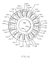
- the disk 116 forming the upper layer 104 has a central opening 120 formed therein. As will be explained in additional detail below, the opening is provided to facilitate support and rotation of the medicament container 100 during its use in a medicament dispensing housing, such as that discussed below with respect to FIG. 5A through 6C .
- Disposed in the disk 116 are two openings 124 disposed opposite one another.
- the two openings receive a mating structure (discussed below) from bottom layer 112 to help hold the medicament container together and to help ensure proper alignment.
- a plurality of openings 128 disposed in upper surface 104 are a plurality of openings 128 disposed in a generally circular pattern.
- the openings align with portions of the middle layer 108 and are used as an indexing and positioning means in conjunction with one embodiment of a medicament dispensing housing.
- the middle layer 108 is also formed by a disk 132 which defines an opening 136.
- the inner wall 132a of the disk 132 which defines the opening 136 is provided with a plurality of notches 140.
- the notches 140 are configured to engage a rotation mechanism of an inhalator housing (not shown) so that the medicament container 100 can be rotated after each use to align medicament with a inspiratory flow channel (not shown).
- the disk 132 forming the middle layer has a pair of openings 144 which are disposed opposite one another and in alignment with the openings 124 in the disk 116 of the upper layer 104. As with the openings 124, the openings 144 receive a mating structure 162 on the lower layer 112 to help align the middle layer 108 and to help retain the middle layer in place.
- a plurality of openings 148 Disposed in the disk 132 is a plurality of openings 148 which are disposed in a generally circular arrangement.
- the openings 148 are configured to be in alignment with the openings 128 in the disk 116 of the upper layer 104.
- the openings are used to align the medicament container 100 with an indexing and positioning means of one embodiment of a medicament dispensing housing (not shown). While the openings 128 and 148 are preferable, those skilled in the art will appreciate that they can be omitted without significantly interfering with the operation of the medicament container 100.
- a plurality of openings 152 which are disposed in concentric circles.
- the openings 152 are generally square or rectangular and extend through the disk 132 at a transverse angle.
- the openings 152 are configured to receive portions of a lancet which punctures the upper layer 104 during use.
- the transverse angle of the openings 152 helps to channel airflow into and out of the medicament container 100 to improve entrainment of the medicament contained therein.
- the portion of the disk 132 between the concentric circles of openings 152 supports the foil or other material of the upper layer 104 so that the opening formed by a lancet puncturing the upper layer is localized.
- a detailed discussion of the lancet mechanism is provided below with respect to FIGs. 3A and 3B .
- the disk 116 defining the upper layer 104 and the disk 132 defining the middle layer 108 are attached to a disk 156 which defines the lower layer 112.
- the disk 156 which forms the lower layer in FIGs. 1A through 1C also forms a carrying tray. This is due to the fact that the disk 156 is preferably made out of a substantially rigid material, such as polycarbonate, to protect the medicament contained within the medicament container 100.
- the disk 156 of the lower layer 112 defines an opening 160.
- the opening 160 is preferably slightly larger than the opening 136 in the middle layer 108 so that it will not interfere with an engagement between a rotation actuation mechanism of an inhalator and the notches 140.
- the mating structures 162 nest in the openings 124 of the upper layer 104 and the openings 144 of the middle layer 108 to help align the upper layer and middle layer with the bottom layer 112.
- the mating structures 162 can also be used to help retain the upper layer 104 and the middle layer 108.
- the disk 156 which defines the lower layer 112 has a plurality of concave receptacles 164 formed therein.
- the receptacles 164 preferably have a generally rectangular opening 168 adjacent the top of the bottom layer 112. From the rectangular opening 168, the receptacles 164 extend downwardly and inwardly so that the receptacles have a generally triangular cross-section.
- the generally triangular cross-section of the receptacles 164 causes the medicament to collect in the bottom of the receptacle where it is less likely to interfere with opening of the receptacle by the lancet mechanism.
- both the top layer and the bottom layer are formed of foil so that a lancet can penetrate both layers. Penetrating through both layers forms an upper air inflow opening and a lower opening for the medicament entrained in the air to exit the blister pack.
- both the air inflow and outflow openings are formed in the upper layer 104 of the medicament container 100.
- the lower layer can be formed of materials which are much more durable than foil, paper, etc.
- the disk 156 of the lower layer 112 (and the disk 132 defining the middle layer 108) be made of plastic which is compatible with the medicament being used.
- the lower layer 112 may be made of polycarbonate, polypropylene, polyurethane or some other easily moldable plastic.
- the lower layer 112 may also be relatively rigid as it will not be punctured by the lancet mechanism.
- a relatively rigid lower layer 112 has several distinct advantages. First, the rigidity helps to protect the medicament container 100 from being damaged during shipping or improper handling. Second, having the receptacles formed with a rigid bottom helps prevent medicament contained therein from being pressed upwardly into contact with the upper layer of the container.
- the substantially rigid triangular receptacles 164 of the lower layer 112 receive and maintain the medicament away from the upper layer 104.
- the medicament will generally be sufficiently far from the upper layer that the foil, etc., will have very little effect on airflow and medicament entrainment.
- FIG. 1B there is shown a bottom, exploded view of the medicament container 100 shown in FIG. 1A , including the upper layer 104, the middle layer 108 and the lower layer 112.
- the view of the upper layer 104 differs little from that shown in FIG. 1A except that it is the underside of the same structure. Thus, the upper layer is numbered in accordance with numbering used in FIG. 1A .
- the bottom view of the middle layer 108 is substantially different than that shown in FIG. 1A . While the bottom view shows the disk 132 defining the hole 136, the openings 144 for receiving the mating structure 162, and the openings 152 for receiving the lancet (not shown), it also includes a plurality of projections 172.
- the projections 172 are positioned between the outer and inner concentric circles defined by the openings 152.
- the projections 172 preferably have a triangular cross-section so that the projections will extend downwardly into the receptacles 164 when the middle layer 108 is attached to the lower layer 112.
- the projections 172 are preferably smaller and less deep than the receptacles 164.
- the projection 172 serves as a flow diverting means to improve medicament entrainment in the inspiratory air.
- FIG. 1B also shows the bottom of the bottom layer 112, including the downwardly extending walls 164a which form the receptacles 164.
- support walls 174 can extend between the walls 164a defining the receptacles.
- the bottom layer 112 can have an outer annular collar 180 disposed about its circumference, and an inner annular collar 184 which circumscribes the opening 160. With such support structures, the bottom layer 112 can be formed from a thin piece of rigid or semi-rigid plastic which is both very light weight and resistant to damage.
- FIG. 1C there is shown a top view of the bottom layer 112 and the receptacles 164 which extend downwardly and inwardly from the openings 168 so as to provide a medicament holding compartment with a generally triangular cross-section. While the mating structures 162 are used to secure and align the middle and upper layers, such structures can also be used to help orient the medicament container 100 within the inhalator. Likewise, a groove 188 can be formed in the annular wall 184 circumscribing the opening 160 to provide orientation of the medicament container.
- the medicament container includes the upper layer 104, the middle layer 108, and the bottom layer 112; the middle layer and the structures formed therein improve medicament entrainment and delivery to the patient.
- FIG. 1D there is shown an exploded view of an alternate embodiment of a medicament container, generally indicated at 100' and made in accordance with the principles of the present invention.
- the medicament container 100' includes an upper layer which is preferentially configured the same as upper layer 104 in FIGs 1A through 1C and is therefor numbered accordingly.
- the medicament carrying tray 186 is preferably formed of a semi-rigid material, such as polyvinyl chloride (PVC), polyvinyl dichloride (PvdC), or fluoronated and/or chloronated homopolymers/copolymers (Aclar).
- PVC polyvinyl chloride
- PvdC polyvinyl dichloride
- Aclar fluoronated and/or chloronated homopolymers/copolymers
- the medicament carrying tray 186 is formed from a disk 188 with a central opening 190.
- the medicament carrying tray layer 186 has a plurality of concave receptacles 192 disposed concentrically around the opening for receiving medicament so that the powdered medicament is held between the upper layer 104 and the medicament carrying tray 186.
- the receptacles 192 preferably have a generally triangular cross-section, with a rounded bottom, and generally rectangular openings 194 adjacent the top of the medicament carrying tray 186, and are otherwise similar to the receptacles 164 discussed in FIGs. 1A through 1C .
- the medicament carrying tray 186 may also include a pair of holes 196 for receiving mating structures of a carrying tray.
- a lower layer Disposed below the medicament carrying tray 186 is a lower layer which, as shown in FIG. 1D , is formed by the disk 156 discussed in FIGs 1A through 1C .
- the receptacles 164 in the disk 156 are preferably sized to nestingly receive the receptacles 192 of the medicament carrying tray 186 so that the upper layer 104 and the medicament carrying tray can be securely held in the lower layer 112.
- the medicament container By providing the medicament container with a semi-rigid carrying tray 186 which then nests in a rigid lower layer 112, one can achieve all of the benefits identified above with having a rigid lower layer, while facilitating manufacture of the medicament container 100'.
- the upper layer 104 is normally attached to the medicament carrying tray 186
- the upper layer and the medicament carrying tray need not be fixedly attached to the lower layer.
- the upper layer and the medicament carrying tray could be removably disposed in a rigid lower layer 112 which could be permanently mounted in the housing of a medicament dispenser. In such a configuration, the user would only need to replace the combination of the upper layer 104 and the medicament carrying tray 186 each time the medicament contained in the medicament carrying tray was exhausted.
- FIG. 1E there is shown yet another embodiment of a medicament container, generally indicated at 100", made in accordance with the principles of the present invention.
- the medicament container 100" includes an upper layer which is preferentially configured in the same manner as upper layer 104 in FIGs 1A through 1C and is therefor numbered accordingly.
- the medicament container 100" Disposed adjacent the upper layer 104, the medicament container 100" also includes a middle layer which is preferably configured in the same manner as the middle layer 108 of FIGs. 1A through 1C and is therefore numbered accordingly.
- the medicament carrying tray is preferably configured in a manner similar to the medicament carrying tray 186 of FIG. 1D and is, therefore, numbered accordingly.
- the medicament carrying tray 186 is preferably formed of a semi-rigid material, such as polyvinyl chloride (PVC), polyvinyl dichloride (PvdC), or fluoronated and/or chloronated homopolymers/copolymers (Aclar), and has a plurality of concave receptacles 192 formed therein.
- PVC polyvinyl chloride
- PvdC polyvinyl dichloride
- Aclar fluoronated and/or chloronated homopolymers/copolymers
- a lower layer 112 Disposed below the medicament carrying tray 186 is a lower layer 112 which, as shown in FIG. 1E , is formed by the disk 156 discussed in FIGs 1A through 1D .
- the receptacles 164 in the disk 156 are preferably sized to receive the receptacles 192 of the medicament carrying tray 186 so that the upper layer 104, the middle layer 108 and the medicament carrying tray can be securely attached to the disk 156 forming the lower layer 112.
- the disk 156 forming the lower layer 112 protects the remaining structures and makes the medicament container 100" much stronger and resistant to damage than the prior art blister packs currently used.
- FIGs. 1A through 1D there are several desirable configurations for the medicament container.
- the remainder of the application except where specifically noted, uses the medicament container 100 shown in FIGs. 1A through 1C .
- the medicament containers 100' ( FIG. 1D ) and 100" ( FIG. 1E ) could also be used with the same highly advantageous results.
- the upper layer 104, the middle layer 108 and the medicament carrying tray 186 can be attached together as an integral unit which is sold or distributed separately from the lower layer 112.
- the lower layer 112 would typically be permanently disposed in an inhalator housing, and the container formed by the upper layer 104, the middle layer 108 and the medicament carrying tray 186 being nestable in the disk 156 forming the lower layer.
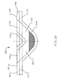
- FIG. 2A shows a side cross-sectional view of one blister of the medicament container 100 made in accordance with a preferred embodiment of the present invention.
- the blister generally indicated at 200, is formed by the upper layer 104, the middle layer 108 and the bottom layer 112.
- the upper layer 104 forms a top covering to the blister 200.
- the openings 152 in the middle layer 108 and the receptacle 164 defined by the generally triangular recess in the bottom layer 112 form a medicament containment area/flow channel 204.
- the upper side of the medicament containment area/flow channel 204 is defined by the triangular projection 172 of the middle layer 108 which extends below the upper surface of the bottom layer (represented by dashed lines 112a).
- the bottom side of the medicament containment area/flow channel 204 is defined by the triangularly recessing wall 164a of the bottom layer 112. As defined between the projection 172 and the wall 164a, the medicament containment area/flow channel 204 is generally elbow shaped, but may be other shapes as well.
- Medicament contained in the medicament containment area/flow channel 204 tends to remain at the bottom of the triangular receptacle 164 and below the lowermost point of the projection 172 so that an airflow path is maintained within the blister 200.
- the medicament is also maintained sufficiently below the upper layer 104 such that when the foil or paper of the upper layer is pierced, it is moved out of the way without engaging the medicament which is in the bottom of the receptacle.
- the risk that the medicament will become trapped by pieces of foil is significantly reduced, as the triangular shape tends to concentrate the medicament in the center of the medicament containment area 204.
- FIGs 2B and 2C there are shown side cross-sectional views of the blister 200 similar to that shown in FIG. 2A .
- a lancet 212 has been moved down so that tapered ends 212a of the lancet have pierced the upper layer 104 of the medicament container 200.
- the tapered ends 212a force the foil, etc., from the upper layer 104 into contact with the upper surface of the wall 164a defining the receptacle 164.
- This pierced material 104a remains against the wall 164a (due to the foil being sheared and bent past its yield point)where it provides almost no interference to entrainment or flow of the medicament 216 in the medicament containment area/flow channel 204.
- the foil is pressed against the walls of the receptacles 192 rather than directly against the lower layer.
- descriptions of pressing the foil against the lower layer should be construed as including pressing the foil against the receptacle of the medicament tray when a medicament tray is included).
- the lancet 212 has been withdrawn from the blister 200 to leave two holes 220 on the same side of the medicament container, but at opposing ends of the medicament containment area/flow channel 204. Extending between the two holes 220 is an elbow-shaped channel which provides a flow path through the upper layer 104, through one 152a of the openings 152 in the middle layer 108, through the receptacle 164 defined by the lower layer 112, back through the other opening 152b and out of the blister 200.
- the airflow channel is further defined by the tapered ends 212a of the lancet 212.
- the tapered ends 212a channel airflow into the blister and help direct airflow coming out of the blister.
- the elbow-shaped configuration formed by the projection 172 of the middle layer 108 and the wall 164a defining the receptacle 164 in the bottom layer 112, provides significantly improved entrainment of the medicament as air flows through the medicament containment area/flow channel 204.
- the airflow of the present configuration impacts the medicament 216 along a curved path which maximizes entrainment.
- FIG. 2C provides more consistent medicament delivery.
- FIG. 2D there is shown a blister 200' made in accordance with another aspect of the present invention.
- the blister 200' preferably includes the upper layer 104, the middle layer 108 and the bottom layer 112. Unlike the configuration discussed in FIGs. 1A through 2C , however, the blister 200' does not have a projection 172 which extends into the medicament receptacle 164.
- a triangular medicament containment area/flow channel 204' is defined by the upper surface of the wall 164a and the lower surface of the upper layer 104. (Of course, the middle layer could be omitted if desired.)
- the triangular flow channel 204' When the upper layer 104 is punctured, the triangular flow channel 204' is opened and air is able to flow through the blister 200' as demonstrated by arrow 228'.
- the triangular airflow channel 204' is generally less efficient at entrainment of medicament than the elbow-shaped medicament containment area/flow channel 204 formed by the projection ( FIGs. 2A through 2C ) because the airflow is not concentrated against the medicament 216 to the same degree.
- the triangular air flow channel 204' is still a marked improvement over conventional blister configurations in which the blister is punctured through the top and bottom of the blister.
- the lancet 212 has a pair of tapered ends 212a which are preferably tapered at an angle similar to the angle of the wall 164a which defines the receptacle 164 ( FIGs 1B through 2D ).
- One or more springs 230 are provided to bias the lancet 212 away from the blister 200.
- a button 234 at the top of the lancet body 212b is depressed. While shown as a separate piece which mates with a flange 238 for attachment, the button 234 could be integrally formed with the other portions of the lancet 212.
- FIG. 3B shows a bottom exploded view of the lancet mechanism 212.
- the button 234 is preferably hollow to receive the flange (238 in FIG. 3A ) disposed at the top end of the lancet body 212b.
- a pair of recesses 240 are preferably formed toward the top of the lancet body 212b to receive the upper end 230a of the springs 230.
- FIG. 4 there is shown a perspective view of a sealing member, generally indicated at 250, formed in accordance with the principles of the present invention.
- the sealing member 250 is configured for placement above the blister 200 which is to be opened to improve airflow through the medicament containment area/flow channel 204 ( FIGs. 2A thorough 2D).
- the sealing member 250 is typically made from a rectangular piece of semi-resilient material, such as silicone rubber.
- the sealing member 250 includes a first opening 254a and a second opening 254b.
- the first and second openings 254a and 254b are spaced apart and configured for alignment with the holes 220 ( FIG. 2C ) disposed at either end of the medicament containment area/flow channel 204 of the blister 200.
- the openings 254a and 254b extend the airflow channel formed by the medicament containment area/flow channel 204 and limit leakage.
- the openings 254a and 254b in the sealing member 250 are preferably provided with a beveled or angled outer sidewall 258a and 258b which is configured for alignment with the wall 164a forming the receptacle 164 ( FIGs. 1A through 2C ).
- the opposing sidewall 262a and 262b may be parallel to the outer sidewall.
- the angled sidewalls 258a and 258b of the sealing member 250 are disposed in alignment with the wall 164a forming the receptacle 164 so as to form a generally continuous wall from the opening 254a, through the medicament containment area/flow channel 204, and to the opening 254b.
- the angled openings 254a and 254b channel airflow smoothly into the medicament containment area/flow channel 204 of the blister 200.
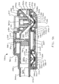
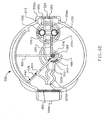
- FIG. 5A there is shown a cross-sectional view of a housing, generally indicated at 300, formed in accordance with the present invention.
- the housing includes an upper, airflow portion 304, and a lower, medicament receiving portion 308, which are preferably attached to one another by a hinge 310 disposed at the distal end 300a of the housing 300.
- the hinge 310 allows a wall 312 of the lower portion 308 to pivot away from the upper portion 304 to expose a cylindrical collar 314 which extends downwardly from the upper portion 304.
- the cylindrical collar 314 is substantially the same size as the opening 160 in the medicament container 100 so that the medicament container can be mounted on and rotated about the collar as shown in FIG. 5A .
- the wall 312 is pivoted back toward the upper portion 304 until a catch 316, which extends downwardly from the upper portion 304, engages a groove 318 along the wall. Once the catch 316 engages the groove 318, the wall 312 is held in a closed position, thereby holding the medicament container 100 in the lower portion 308.
- the upper airflow portion 304 defines a medicament airflow channel 320 which extends from a first, distal end 304a to a second, proximal end 304b of the upper portion.
- a grate 324 is disposed at the first end 320a of the medicament airflow channel 320 to limit entry of foreign bodies into the channel. From the grate 324, the channel 320 is tapered downwardly toward the second, lower portion 308 which houses the medicament container 100.
- the lancet 212 is disposed adjacent the distal end 320a of the channel 320 so that the tapered end 212a is disposed over the blister 200 disposed in the lower portion 308, and so that the tapered end is in alignment with the wall 328 which defines the tapered portion of the channel 320.
- the tapered end 212a helps direct airflow to the blister 200 in the lower portion 308 when the lancet 212 is in a resting position.
- the lower side of the channel 320 is formed by a lower wall 332 of the first, upper portion 304, and the angled sidewall 258a of the opening 254a of the sealing member 250. As shown in FIG. 5A , the lower wall 332 extends straight and then angles downwardly parallel to the wall 328 and the tapered end 212a of the lancet 212. Thus, the initial portion 320a of the airflow channel 320 narrows as it approaches the blister 200, thereby increasing the speed of the airflow.
- the initial portion of the airflow channel 320a ends at the upper layer 104 of the medicament container 100. Until the upper layer 104 is punctured by the lancet 212, airflow through the channel 320 is prevented. Airflow through the channel 320 once the lancet 212 punctures the upper layer 104 is discussed in detail with respect to FIGs. 5B and 5C below.
- the airflow channel 320 continues through the upper portion 304 at the opposing side of the blister 200.
- the channel 320 continues from the opening 254b in the sealing member 250.
- the channel 320 is defined on its upper side by the tapered end 212a of the lancet 212 and by a wall 340 which gradually curves until it is disposed in a horizontal orientation.
- the lower side of the channel 320 is formed by the angled sidewall 258b of the sealing member 250 and a wall 344 which has an angled distal end and then extends horizontally.
- the wall 344 can also form the base for the cylindrical collar 314 and the catch 316.
- the positions of the walls 340 and 344 form a channel whose distal portions 320b have approximately the same cross-sectional area as the initial portion prior to narrowing.
- the channel 320 is defined by a generally cylindrical wall 344b which forms a mouthpiece through which the user can inhale.
- a rotatable airflow control member 350 Disposed along the airflow channel 320 is a rotatable airflow control member 350. As will be discussed in detail in FIGs. 6A through 6C , the airflow control member 350 selectively limits airflow through airflow channel 320 to improve deep lung deposition of the medicament 216 contained in the medicament container 100.
- FIG. 5A also shows several other structures which assist in the functioning of the housing 300.
- the housing 300 includes an upper wall 360.
- the upper wall 360 holds the walls 328 and 340 in place and helps properly position the lancet 212.
- the upper wall 360 also has an opening 364 which receives a post 368 of the rotatable airflow control member 350.
- a similar opening 372 is also formed in the wall 340, and a collar 376 can be disposed around the post 368 between the walls 340 and 360.
- the housing 300 also includes a support structure 380 which fits between the tapered ends 212a of the lancet 212, and a cap 384 which is disposed above the upper wall 360.
- the cap 384 keeps dust from entering around the post 368, seals the primary air cavity and contains the spiral torsion spring which creates bias for the air vane 430 discussed below.
- FIG. 5B there is shown a side cross-sectional view of the housing 300 similar to that of FIG. 5A .
- the primary difference in FIG. 5B is that the button 234 of the lancet 212 has been pressed downwardly so that the tapered ends 212a on the opposite end of the lancet are advanced through the upper layer 104 ( FIG. 5A ) of the blister 200 and into the medicament containment area/flow channel 204.
- the range of travel of the lancet 212 is limited by interaction between the flange 212c of the lancet body 212b and the upper wall 360 and the walls 328 and 340, and by the upper surface of the lower layer 112.
- the tapered ends 212a of the lancet 212 extend down into the medicament containment area/flow channel 204, the tapered ends shear and/or puncture the upper layer and force the sheared portions of the upper layer 104 against the wall 164a which defines the receptacle 164.
- the sheared portions of the upper layer 104 are pushed into a position where they provide virtually no interference to airflow through the medicament containment area/flow channel 204, and do not interfere with medicament entrainment.
- the medicament container 100 is preferably formed with a bottom layer 112 which is rigid or semi-rigid (as opposed to the flexible foil common in the prior art).
- the rigidity helps to support the medicament container 100.
- a pair of support walls 390 preferably extend upwardly from the wall 312 of the lower portion 308 of the housing 300. The support walls 390 provide additional assurance against the medicament containment area/flow channel 204 being compressed during actuation of the lancet 212.
- FIG. 5C shows a side cross-sectional view of the housing 300 similar to that of FIGs. 5A and 5B .
- the lancet 212 has been returned to its original position. This is accomplished by the springs 230 which are shown in FIG. 3B , but which are not visible with the cross-sectional view shown.
- the distal most tapered end 212a again is in alignment with the wall 328 to define an upper boundary for the initial portion 320a of the airflow channel 320, and the proximal most tapered end 212a is in alignment with the wall 340 to form a middle portion of the airflow channel. Because the upper layer 104 has been punctured and pressed against the wall 164a forming the receptacle 164, airflow through the medicament containment area/flow channel 204 of the blister 200 is allowed with virtually no interference from the cut portions of the upper layer.
- the flow of air entrained medicament is delayed momentarily. This allows the user to obtain a predetermined air-flow rate prior to delivery of the medicament, thereby enhancing deep lung deposition of the medicament.
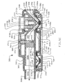
- FIG. 6A there is shown a plan view of the internal components of the housing 300, in accordance with the principles of the present invention.
- the housing 300 has a distal end 300a (i.e. the end which is positioned away from the patient) and a proximal end 300b through which the patient inhales.
- Disposed at the distal end 300a is a filter or grate 324. Air passing through the grate 324 follows one of two paths.
- the air will turn toward one side of the housing 300, following a primary airflow path as demonstrated by arrow 420.
- the primary air vane 430 is preferably attached to the collar 376 which is mounted on the post 368.
- the airflow through the primary airflow path 420 moves the primary air vane 430 between an initial position, shown in FIG. 6A and a final position, shown in FIG. 6C , in which the primary air vane engages a wall 434 having a opening 438 formed therein.
- a sealing member 442 such as an O-ring, is disposed about the opening for purposes discussed below.
- the air flowing through the grate 324 may also follow a secondary flow path 450, which is defined by the airflow channel 320 discussed with respect to FIGs. 5A through 5C .
- Disposed along the airflow channel 320 is the lancet 212 which is biased in a resting position by a pair of springs 230.
- Disposed below the lancet 212 is the sealing member 250 and the blister 200.
- the openings 254a and 254b in the sealing member 250 correspond with the tapered ends (not shown in FIGs. 6A through 6B ).
- the channel 320 extends generally linearly until it is obstructed by the airflow control member 350.
- the middle portion 320b of the airflow channel 320 follows a winding or zig-zag path. This forms a deagglomeration channel.
- the deagglomeration channel 320b is configured to break up any large agglomerations of medicament which might be present. Because of their larger weight, such agglomerations are less able to turn suddenly with the airflow.
- large agglomerations will continue moving forward until they forcibly impact the walls 320d defining the deagglomeration channel 320b. The force of impact will generally break up the agglomerations.
- the medicament passes through a mouthpiece filter 460.
- the mouthpiece filter 460 stops any agglomerations or foreign bodies which may have made it through the grate 324 of the deagglomeration channel 320b.
- the primary air vane 430 has been moved approximately half way (or 45 degrees) from the initial position shown in FIG. 6A to the wall 434.
- a 45 degree movement of the primary air vane 430 causes a like movement in the airflow control member 350 which forms the airflow control valve 470 in the airflow channel 320.
- the airflow control member 350 recedes into a channel 480.
- the primary air vane 430 pivots into its final, closed position shown in FIG. 6C .
- the primary air vane 430 engages the sealing member 442 disposed about the opening 438 in the wall 434 and prevents further airflow through the opening.
- airflow through the primary airflow path 420 is terminated.
- Movement of the primary air vane 430 into the final, closed position also moves the air control member 350 completely into the channel 480, thereby fully opening the air control valve 470. With the primary airflow path 420 fully closed, and the secondary air path 450 fully open, all further inhaled air travels through the airflow channel 320. The airflow entrains the medicament 216 in the blister 200 and carries it to the user. Because of the time required for movement of primary air vane 430 from the initial position ( FIG. 6A ) to the final position ( FIG. 6C ), the user is able to achieve a predetermined inhalation rate and his or her lungs are partially inflated before the airflow through the airflow channel 320 carries medicaments to the user's lungs. This increases deep lung penetration of the medicaments and increases their efficacy for those suffering from asthma, etc.
- the momentary delay in airflow occurring through the secondary airflow path 450 (i.e. the airflow channel 320) also increases the flow rate of the airflow prior to its initial engagement with the medicament.
- the increased velocity of the airflow further helps to entrain the medicament in the medicament containment area/flow channel 204 as the air flows therethrough and to deagglomerate larger particles by particle/particle interaction and impacting against the impact surfaces.
- the primary air vane 430 returns to its initial position. This can be effected by having the primary air vane 430 being spring biased into the initial position, or by simply constructing the housing such that the weight of the primary air vane or the airflow control member 350 causes the two structures to return to the positions shown in FIG. 6A .
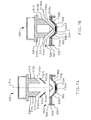
- FIG. 7A there is shown a cross-sectional view of a lancet, generally indicated at 500 and a blister, generally indicated at 504.
- the lancet 500 includes a body 508 which has two prongs 512 which extend generally parallel to one another. At the bottom of the prongs 512 are a pair of tapered ends 512a. Preferably, the tapered ends 512a each taper toward a longitudinal center axis 514 of the lancet 500.
- each prong 512 has a channel 516 disposed therein adjacent the tapered end 512a.
- the proximal prong 512b has a channel 516a which extends downwardly at an angle, typically between about 30 and 45 degrees, as it extends toward the axis 514. (Of course, the channels could be disposed at an angle less than 30 degrees or greater than 45 degrees.)
- the distal prong 512c has a channel 516b which extends upwardly and proximally (i.e., toward the user) away from the axis 514 in a similar orientation.
- the blister 504 has a medicament containment area/flow channel 520 in which medicament 524 is stored.
- the medicament containment area 520 is defined at an upper extreme by an upper layer 528 which is typically formed of foil or some other readily puncturable material.
- the bottom of the medicament containment area 520 is defined by a lower layer 532 which has a wall 534 forming a receptacle 538.
- a middle layer 542 may be disposed between the upper layer 528 and the lower layer 532. As with the middle layer 108, the middle layer 542 preferably includes a projection 546 disposed in the receptacle 538 to form the substantially elbow-shaped medicament containment area/flow channel 520.
- the blister 504 is different from blister 200. While blister 200 is generally triangular in cross-section, blister 504 is trapezoidal. Other configurations could also be used.
- FIG. 7B shows a side cross-sectional view of the lancet 500 and blister 504 with the lancet having been advanced from through the first layer 528 and into a second position.
- the tapered ends 512a of the lancet 500 are disposed against the wall 534.
- the portion of the prongs 512 forming the bottom wall defining the channels 516 is disposed in alignment with the upper surface of portion of wall 534 which holds the medicament 524.
- the channels 516 in the lancet 500 and the medicament container area/flow channel 520 form a portion of an airflow channel represented by arrow 560.
- the lancet 500 will be disposed in a housing (such as housing 300) so that channel 516 forms part of the initial portion 320a of the airflow channel 320.
- the portion of the prong 512 defining the top of the channel 516a is in alignment with the wall (such as wall 328) defining the top of the initial portion of the airflow channel (such as initial portion 320a).
- channel 516b would be in alignment with the channel 320 as it extends from the blister 504 toward the user.
- Inhalation by the user causes air to flow through a distal portion of a housing (such as housing 300), through the channel 516a and into the medicament containment area/flow channel 520.
- the air impacts the medicament 524 and entrains it.
- the entrained medicament 524 is then carried out the second channel 516b in the lancet 500 and through the remainder of the airflow channel (such as channel 320).
- the lancet 500 remains in a second, resting position rather than returning to its original position prior to inhalation by the user.
- This can be readily accomplished by provided a spring catch which is common on numerous electronic and other devices.
- a spring catch which is common on numerous electronic and other devices.
- receptacles 164 and 538 which are either triangular or trapezoidal, in light of the present disclosure, those skilled in the art will appreciate that other cross-sectional shapes could also be used.
- the receptacle 164 or 538 could have a cross-sectional shape which is semi-circular, semi-elliptical, etc.
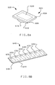
- the blister 600 includes an upper layer 604 which is formed of a readily puncturable or shearable material, such as foil or plastic.
- the upper layer 604 is supported by a middle layer 608 and a lower layer 612.
- the middle layer and the lower layer are preferably made of a semi-rigid or rigid plastic or similar material.
- the blister 600 includes a receptacle which is formed by the wall 616 forming the lower layer 612.
- the receptacle preferably has a generally rectangular opening, indicated at 620 and extends downwardly with a triangular, semi-circular, trapezoidal or semi-elliptical shape. If a projection is used, such as those shown at 172 and 546 ( FIGs. 1A and 7B ), it is preferred that the projection have a similar cross-sectional configuration as that of the receptacle. Thus, when the receptacle is generally triangular, the projection is preferably generally triangular.
- the single blister 600 forms a medicament container, generally indicated 624.
- the housing 300 discussed above could be readily modified to hold a single blister 600.
- the wall 312 (see FIGs. 5A through 5C )could be shortened so that it simply receives a single blister 600 which is positioned beneath the lancet 212.
- the housing 300 ( FIGs. 5A through 5C ) could be modified to receive blisters, such as those indicated at 630 in FIG. 8B , which are disposed in a linear or rectilinear array 640. After each use, the array 640 is simply advanced one position until all of the blisters have been used.
- the blisters 630 are otherwise formed in accordance with the embodiments discussed above, and include at least a readily puncturable or shearable upper layer 644 from a flexible plastic or foil and a semi-rigid or rigid lower layer 648.
- semi-rigid it is meant that the lower layer and the receptacle formed therein will maintain its shape during normal usage. This is in contrast to the prior art foil and flexible plastic medicament containers of the prior art wherein the receptacle can be readily deformed.
- the rigid or semi-rigid lower layer helps maintain the medicament in the desired location and makes the medicament container more durable.
Applications Claiming Priority (2)
| Application Number | Priority Date | Filing Date | Title |
|---|---|---|---|
| US09/568,643 US6948494B1 (en) | 2000-05-10 | 2000-05-10 | Medicament container with same side airflow inlet and outlet and method of use |
| EP01923035A EP1283731B1 (en) | 2000-05-10 | 2001-04-02 | Medicament dispensing system with a medicament container with same side airflow inlet and outlet |
Related Parent Applications (1)
| Application Number | Title | Priority Date | Filing Date |
|---|---|---|---|
| EP01923035A Division EP1283731B1 (en) | 2000-05-10 | 2001-04-02 | Medicament dispensing system with a medicament container with same side airflow inlet and outlet |
Publications (2)
| Publication Number | Publication Date |
|---|---|
| EP1726324A1 EP1726324A1 (en) | 2006-11-29 |
| EP1726324B1 true EP1726324B1 (en) | 2009-07-01 |
Family
ID=24272127
Family Applications (2)
| Application Number | Title | Priority Date | Filing Date |
|---|---|---|---|
| EP01923035A Expired - Lifetime EP1283731B1 (en) | 2000-05-10 | 2001-04-02 | Medicament dispensing system with a medicament container with same side airflow inlet and outlet |
| EP06016891A Expired - Lifetime EP1726324B1 (en) | 2000-05-10 | 2001-04-02 | Medicament container with same side airflow inlet and outlet |
Family Applications Before (1)
| Application Number | Title | Priority Date | Filing Date |
|---|---|---|---|
| EP01923035A Expired - Lifetime EP1283731B1 (en) | 2000-05-10 | 2001-04-02 | Medicament dispensing system with a medicament container with same side airflow inlet and outlet |
Country Status (11)
| Country | Link |
|---|---|
| US (3) | US6948494B1 (es) |
| EP (2) | EP1283731B1 (es) |
| JP (1) | JP4754758B2 (es) |
| AT (2) | ATE435047T1 (es) |
| AU (2) | AU2001249773B2 (es) |
| CA (1) | CA2404225C (es) |
| DE (2) | DE60139166D1 (es) |
| DK (1) | DK1283731T3 (es) |
| ES (1) | ES2275672T3 (es) |
| PT (1) | PT1283731E (es) |
| WO (1) | WO2001085097A2 (es) |
Families Citing this family (100)
| Publication number | Priority date | Publication date | Assignee | Title |
|---|---|---|---|---|
| JP4212244B2 (ja) * | 1999-04-07 | 2009-01-21 | イベント メディカル リミテッド | 人工呼吸装置 |
| US9006175B2 (en) | 1999-06-29 | 2015-04-14 | Mannkind Corporation | Potentiation of glucose elimination |
| US6948494B1 (en) * | 2000-05-10 | 2005-09-27 | Innovative Devices, Llc. | Medicament container with same side airflow inlet and outlet and method of use |
| US6766799B2 (en) * | 2001-04-16 | 2004-07-27 | Advanced Inhalation Research, Inc. | Inhalation device |
| GB0120018D0 (en) * | 2001-08-16 | 2001-10-10 | Meridica Ltd | Pack containing medicament and dispensing device |
| ES2425392T3 (es) | 2002-03-20 | 2013-10-15 | Mannkind Corporation | Cartucho para un aparato de inhalación |
| CA2522231A1 (en) * | 2003-04-14 | 2004-10-21 | Vectura Ltd | Pharmaceutical compositions comprising apomorphine for pulmonary inhalation |
| GB0315509D0 (en) * | 2003-07-02 | 2003-08-06 | Meridica Ltd | Dispensing device |
| EP1663025A4 (en) * | 2003-08-20 | 2010-03-24 | Facet Technologies Llc | BLOOD COLLECTION DEVICE |
| GB0320171D0 (en) | 2003-08-28 | 2003-10-01 | Optinose As | Delivery devices |
| WO2005041848A2 (en) * | 2003-10-27 | 2005-05-12 | Oriel Therapeutics, Inc. | Dry powder drug containment system packages with tabs, inhalers and associated methods |
| ATE486064T1 (de) | 2004-08-20 | 2010-11-15 | Mannkind Corp | Katalyse der diketopiperazinsynthese |
| PL1791542T3 (pl) | 2004-08-23 | 2015-11-30 | Mannkind Corp | Sole diketopiperazyny do dostarczania leków |
| FR2877925B1 (fr) * | 2004-11-16 | 2008-09-19 | Valois Sas | Dispositif de distribution de produit fluide. |
| FR2881119B1 (fr) * | 2005-01-25 | 2010-07-30 | Valois Sas | Dispositif de distribution de produit fluide. |
| GB0507711D0 (en) * | 2005-04-15 | 2005-05-25 | Vectura Group Plc | Improved blister piercing |
| US8763605B2 (en) | 2005-07-20 | 2014-07-01 | Manta Devices, Llc | Inhalation device |
| DE102005038619A1 (de) | 2005-08-16 | 2007-02-22 | Pari GmbH Spezialisten für effektive Inhalation | Inhalationstherapievorrichtung mit einer Ampulle für die Bevorratung eines zu vernebelnden Medikaments |
| AU2006290870B2 (en) | 2005-09-14 | 2013-02-28 | Mannkind Corporation | Method of drug formulation based on increasing the affinity of active agents for crystalline microparticle surfaces |
| DE102005057685A1 (de) * | 2005-12-01 | 2007-06-06 | Boehringer Ingelheim Pharma Gmbh & Co. Kg | Inhalator und Speicher für eine trockene Arzneimittelformulierung sowie diesbezügliche Verfahren und Verwendung |
| EP2497484A3 (en) | 2006-02-22 | 2012-11-07 | MannKind Corporation | A method for improving the pharmaceutic properties of microparticles comprising diketopiperazine and an active agent |
| EP1844805A1 (de) * | 2006-04-13 | 2007-10-17 | Boehringer Ingelheim Pharma GmbH & Co.KG | Inhalator |
| EP1844806A1 (de) * | 2006-04-13 | 2007-10-17 | Boehringer Ingelheim Pharma GmbH | Medikamenten-Ausgabevorrichtung, Medikamentenmagazin dafür, und Verfahren zur Entnahme eines Medikaments aus einer Medikamentenkammer |
| US20090250058A1 (en) * | 2006-07-14 | 2009-10-08 | Astrazeneca Ab | Inhalation System and Delivery Device for the Administration of a Drug in the Form of Dry Powder |
| GB0621957D0 (en) * | 2006-11-03 | 2006-12-13 | Vectura Group Plc | Inhaler devices and bespoke pharmaceutical compositions |
| CA2683724A1 (en) * | 2007-04-30 | 2009-01-15 | Sun Pharma Advanced Research Company Limited | Inhalation device |
| US11224704B2 (en) | 2007-07-06 | 2022-01-18 | Manta Devices, Llc | Dose delivery device for inhalation |
| EP3453418A1 (en) | 2007-07-06 | 2019-03-13 | Manta Devices, LLC | Delivery device and related methods |
| DE102007056462B4 (de) * | 2007-11-23 | 2011-10-27 | Pari Pharma Gmbh | Einwegampulle für eine Vorrichtung zur Erzeugung von Aerosolen |
| EP2224984A4 (en) * | 2007-12-20 | 2013-10-30 | Astrazeneca Ab | DISPENSER AND METHOD FOR DRIVING POWDER IN AIR FLOW 537 |
| EP2077132A1 (en) | 2008-01-02 | 2009-07-08 | Boehringer Ingelheim Pharma GmbH & Co. KG | Dispensing device, storage device and method for dispensing a formulation |
| EP2082763A1 (en) * | 2008-01-24 | 2009-07-29 | Boehringer Ingelheim International Gmbh | Inhaler |
| EP2082762A1 (en) * | 2008-01-24 | 2009-07-29 | Boehringer Ingelheim International Gmbh | Inhaler |
| US8397718B2 (en) * | 2008-02-12 | 2013-03-19 | Astrazeneca Ab | Inhaler comprising a base having at least one sealed cavity containing medicament |
| JP5491418B2 (ja) * | 2008-02-12 | 2014-05-14 | アストラゼネカ・アクチエボラーグ | 複数の薬剤収容封止キャビティを有する基部を備える吸入器 |
| US8485180B2 (en) | 2008-06-13 | 2013-07-16 | Mannkind Corporation | Dry powder drug delivery system |
| DK2570147T3 (da) | 2008-06-13 | 2018-01-29 | Mannkind Corp | Tørpulverinhalator og system til lægemiddelindgivelse |
| KR101628410B1 (ko) | 2008-06-20 | 2016-06-08 | 맨카인드 코포레이션 | 흡입 활동에 관한 실시간 프로파일링을 위한 대화형 장치 및 방법 |
| TW201002379A (en) * | 2008-07-01 | 2010-01-16 | Galemed Corp | Auxiliary tool for babyaerosol and oxygen therapy |
| TWI532497B (zh) | 2008-08-11 | 2016-05-11 | 曼凱公司 | 超快起作用胰島素之用途 |
| MX2011003233A (es) | 2008-09-26 | 2011-04-28 | Oriel Therapeutics Inc | Inhaladores de polvo seco con miembros de perforacion doble y dispositivos y metodos relacionados. |
| MX2011003244A (es) | 2008-09-26 | 2011-04-28 | Oriel Therapeutics Inc | Inhaladores con discos de vias aereas con canales de vias aereas discretas y discos y metodos relacionados. |
| EP2346554B1 (en) * | 2008-09-26 | 2015-09-16 | Oriel Therapeutics, Inc. | Inhaler mechanisms with radially biased piercers and related methods |
| WO2010039201A2 (en) * | 2008-09-30 | 2010-04-08 | Oriel Therapeutics, Inc. | Dry powder inhalers with multi-facet surface deagglomeration chambers and related devices and methods |
| CA2732827C (en) * | 2008-10-01 | 2016-10-11 | Oriel Therapeutics, Inc. | Dry powder inhalers with rotating piercing mechanisms and related devices and methods |
| WO2010063286A2 (en) | 2008-12-04 | 2010-06-10 | Nordicaryan Aps | A hand-held inhaler |
| EP2198907A1 (en) * | 2008-12-19 | 2010-06-23 | Boehringer Ingelheim International GmbH | Inhaler |
| US8314106B2 (en) | 2008-12-29 | 2012-11-20 | Mannkind Corporation | Substituted diketopiperazine analogs for use as drug delivery agents |
| US8550074B2 (en) | 2009-01-15 | 2013-10-08 | Manta Devices, Llc | Delivery device and related methods |
| KR100909342B1 (ko) * | 2009-01-22 | 2009-07-23 | 박효남 | 미세조절이 가능한 약액조절장치 |
| EP2210638B1 (en) * | 2009-01-26 | 2013-03-27 | Boehringer Ingelheim International GmbH | Inhaler |
| CA2754595C (en) | 2009-03-11 | 2017-06-27 | Mannkind Corporation | Apparatus, system and method for measuring resistance of an inhaler |
| US10011906B2 (en) | 2009-03-31 | 2018-07-03 | Beohringer Ingelheim International Gmbh | Method for coating a surface of a component |
| EP3508239B1 (de) | 2009-05-18 | 2020-12-23 | Boehringer Ingelheim International GmbH | Adapter, inhalationseinrichtung und zerstäuber |
| US8734845B2 (en) | 2009-06-12 | 2014-05-27 | Mannkind Corporation | Diketopiperazine microparticles with defined specific surface areas |
| WO2011002406A1 (en) | 2009-07-01 | 2011-01-06 | Astrazeneca Ab | Dispenser and method for entraining powder in an airflow |
| CA2778698A1 (en) | 2009-11-03 | 2011-05-12 | Mannkind Corporation | An apparatus and method for simulating inhalation efforts |
| US10016568B2 (en) | 2009-11-25 | 2018-07-10 | Boehringer Ingelheim International Gmbh | Nebulizer |
| EP2504051B1 (en) | 2009-11-25 | 2019-09-04 | Boehringer Ingelheim International GmbH | Nebulizer |
| JP5715640B2 (ja) | 2009-11-25 | 2015-05-13 | ベーリンガー インゲルハイム インターナショナル ゲゼルシャフト ミット ベシュレンクテル ハフツング | ネブライザ |
| WO2011116293A2 (en) | 2010-03-19 | 2011-09-22 | Manta Devices, Llc | Delivery device and related methods |
| USD635246S1 (en) | 2010-03-26 | 2011-03-29 | Oriel Therapeutics, Inc. | Dose disk for dry powder inhalers |
| USD641076S1 (en) | 2010-03-26 | 2011-07-05 | Oriel Therapeutics, Inc. | Dry powder inhaler |
| TWM388940U (en) * | 2010-04-16 | 2010-09-21 | Atlantean Corp | Press-type medical spray generator and pressing mechanism thereof |
| RU2531455C2 (ru) | 2010-06-21 | 2014-10-20 | Маннкайнд Корпорейшн | Системы и способы доставки сухих порошковых лекарств |
| EP2585151B1 (en) | 2010-06-24 | 2018-04-04 | Boehringer Ingelheim International GmbH | Nebulizer |
| EP2694220B1 (de) | 2011-04-01 | 2020-05-06 | Boehringer Ingelheim International GmbH | Medizinisches gerät mit behälter |
| MY180552A (en) | 2011-04-01 | 2020-12-02 | Mannkind Corp | Blister package for pharmaceutical cartridges |
| US9827384B2 (en) | 2011-05-23 | 2017-11-28 | Boehringer Ingelheim International Gmbh | Nebulizer |
| WO2012174472A1 (en) | 2011-06-17 | 2012-12-20 | Mannkind Corporation | High capacity diketopiperazine microparticles |
| US11103659B2 (en) | 2011-07-06 | 2021-08-31 | Manta Devices, Llc | Delivery device and related methods |
| WO2013063160A1 (en) | 2011-10-24 | 2013-05-02 | Mannkind Corporation | Methods and compositions for treating pain |
| CN102580178B (zh) * | 2012-03-16 | 2013-09-04 | 广西大学 | 一种静脉输液自动续液提醒器 |
| WO2013152894A1 (de) | 2012-04-13 | 2013-10-17 | Boehringer Ingelheim International Gmbh | Zerstäuber mit kodiermitteln |
| US9649454B2 (en) | 2012-05-03 | 2017-05-16 | Manta Devices, Llc | Delivery device and related methods |
| CN104470569B (zh) * | 2012-06-28 | 2018-04-27 | 美国政府(由卫生和人类服务部的部长所代表) | 用于疫苗和其它治疗试剂的鼻干粉递送系统 |
| CA2878457C (en) * | 2012-07-12 | 2021-01-19 | Mannkind Corporation | Dry powder drug delivery systems and methods |
| WO2014066856A1 (en) | 2012-10-26 | 2014-05-01 | Mannkind Corporation | Inhalable influenza vaccine compositions and methods |
| GB201301192D0 (en) | 2013-01-23 | 2013-03-06 | Vectura Delivery Devices Ltd | A blister piercing element for a dry powder inhaler |
| BR112015023168B1 (pt) | 2013-03-15 | 2021-08-10 | Mannkind Corporation | Composição de 3,6-bis(n-fumaril-4-aminobutil)-2,5-dicetopiperazina cristalina, método de produção de partículas de 3,6-bis(n-fumaril-4-aminobutil)-2,5-dicetopiperazina e uso de uma composição de dicetopiperazina cristalina |
| CN114848614A (zh) | 2013-07-18 | 2022-08-05 | 曼金德公司 | 热稳定性干粉药物组合物和方法 |
| CA2920488C (en) | 2013-08-05 | 2022-04-26 | Mannkind Corporation | Insufflation apparatus and methods |
| EP2835146B1 (en) | 2013-08-09 | 2020-09-30 | Boehringer Ingelheim International GmbH | Nebulizer |
| WO2015018904A1 (en) | 2013-08-09 | 2015-02-12 | Boehringer Ingelheim International Gmbh | Nebulizer |
| WO2015034709A1 (en) | 2013-09-04 | 2015-03-12 | 3M Innovative Properties Company | Dry-powder inhaler and method |
| US10307464B2 (en) | 2014-03-28 | 2019-06-04 | Mannkind Corporation | Use of ultrarapid acting insulin |
| WO2015168572A2 (en) | 2014-05-02 | 2015-11-05 | Manta Devices, Llc | Delivery device and related methods |
| HUE055604T2 (hu) | 2014-05-07 | 2021-12-28 | Boehringer Ingelheim Int | Porlasztó |
| JP6580070B2 (ja) | 2014-05-07 | 2019-09-25 | ベーリンガー インゲルハイム インターナショナル ゲゼルシャフト ミット ベシュレンクテル ハフツング | 容器、ネブライザ、及び使用 |
| BR112016023932B1 (pt) | 2014-05-07 | 2022-11-29 | Boehringer Ingelheim International Gmbh | Nebulizador |
| USD732730S1 (en) * | 2014-08-05 | 2015-06-23 | General Luminaire Co., Ltd. | Spliceable lamp panel |
| USD733959S1 (en) * | 2014-08-05 | 2015-07-07 | General Luminaire Co., Ltd. | Spliceable lamp panel |
| US10561806B2 (en) | 2014-10-02 | 2020-02-18 | Mannkind Corporation | Mouthpiece cover for an inhaler |
| WO2016168274A1 (en) * | 2015-04-15 | 2016-10-20 | Sansa Corporation (Barbados) Inc. | Dry powder inhaler and method of use |
| DE102016119789A1 (de) * | 2016-07-04 | 2018-01-04 | Alfred Von Schuckmann | Vorrichtung zur Ausgabe einer durch Luft austragbaren Substanz |
| JP6972147B2 (ja) * | 2017-03-01 | 2021-11-24 | ヴァイアヴィ・ソリューションズ・インコーポレイテッドViavi Solutions Inc. | 機能性コーティングを有するラメラ粒子 |
| CA3096576A1 (en) * | 2017-09-28 | 2019-04-04 | Iconovo Ab | A dry powder inhaler with means for enhancing dispersion |
| WO2020135920A1 (en) * | 2018-12-28 | 2020-07-02 | Université Libre de Bruxelles | Kit for inhaled chemotherapy, and treatment of lung cancer with said kit |
| US11493509B2 (en) * | 2020-04-16 | 2022-11-08 | 2Pi-Sigma Corp. | Lateral flow assay for detecting multiple proteins of a pathogen |
| WO2024044257A1 (en) * | 2022-08-23 | 2024-02-29 | Virginia Commonwealth University | Air-jet dry powder inhaler (dpi) with passive cyclic loading of the formulation |
Family Cites Families (96)
| Publication number | Priority date | Publication date | Assignee | Title |
|---|---|---|---|---|
| US3469748A (en) * | 1967-02-20 | 1969-09-30 | Owens Illinois Inc | Closure seal and cap |
| US3587944A (en) * | 1968-10-07 | 1971-06-28 | Harold T Pehr | Dispensers with integral removable closures |
| US3687691A (en) * | 1970-08-10 | 1972-08-29 | Richardson Merrell Inc | Method of incorporating volatile aromatics into hard candy |
| IT941426B (it) | 1971-07-17 | 1973-03-01 | Isf Spa | Inalatore a camera di turbinio per sostanze medicamentose polveriformi |
| FR2224175B1 (es) | 1973-04-04 | 1978-04-14 | Isf Spa | |
| GB1479283A (en) | 1973-07-23 | 1977-07-13 | Bespak Industries Ltd | Inhaler for powdered medicament |
| IT1016489B (it) | 1974-03-18 | 1977-05-30 | Isf Spa | Inalatore |
| US3971377A (en) * | 1974-06-10 | 1976-07-27 | Alza Corporation | Medicament dispensing process for inhalation therapy |
| IT1017153B (it) | 1974-07-15 | 1977-07-20 | Isf Spa | Apparecchio per inalazioni |
| IT1116047B (it) | 1979-04-27 | 1986-02-10 | Sigma Tau Ind Farmaceuti | Dispositivo per la rapida inalazione di farmaci in polvere da parte di persone sofferenti di asma |
| EP0041783B1 (en) | 1980-06-06 | 1984-12-05 | FISONS plc | Inhalation device for powdered medicaments |
| US4369901A (en) * | 1981-03-05 | 1983-01-25 | Hidding Walter E | Snap-up cover for spice dispenser |
| SE438261B (sv) | 1981-07-08 | 1985-04-15 | Draco Ab | Anvendning i dosinhalator av ett perforerat membran |
| US4388931A (en) * | 1981-09-30 | 1983-06-21 | Leading Lady Foundations, Inc. | Brassiere with improved seam |
| US4437593A (en) * | 1982-07-12 | 1984-03-20 | Three Sisters Ranch Enterprises | Overcap for spice canister |
| US4778054A (en) | 1982-10-08 | 1988-10-18 | Glaxo Group Limited | Pack for administering medicaments to patients |
| CA1224992A (en) | 1982-10-08 | 1987-08-04 | Robert E. Newell | Device for administering medicament to patients |
| GB8328808D0 (en) | 1983-10-28 | 1983-11-30 | Riker Laboratories Inc | Inhalation responsive dispensers |
| FI69963C (fi) | 1984-10-04 | 1986-09-12 | Orion Yhtymae Oy | Doseringsanordning |
| US4805811A (en) | 1985-03-29 | 1989-02-21 | Aktiebolaget Draco | Dosage device |
| SE448277B (sv) | 1985-04-12 | 1987-02-09 | Draco Ab | Indikeringsanordning vid en doseringsanordning for lekemedel |
| FI88112C (fi) | 1985-07-30 | 1993-04-13 | Glaxo Group Ltd | Anordning foer administrering av laekemedel till patienter |
| DE3645056C2 (de) * | 1986-11-25 | 1994-12-08 | Folkmar Jan | Deckel, insbesondere für Streudosen |
| US4875576A (en) * | 1988-02-05 | 1989-10-24 | Torgrimson Lee A | Mixing kit |
| IT1228459B (it) * | 1989-02-23 | 1991-06-19 | Phidea S R L | Inalatore con svuotamento regolare e completo della capsula. |
| GB8909891D0 (en) | 1989-04-28 | 1989-06-14 | Riker Laboratories Inc | Device |
| IT1237118B (it) | 1989-10-27 | 1993-05-18 | Miat Spa | Inalatore multidose per farmaci in polvere. |
| US5201308A (en) | 1990-02-14 | 1993-04-13 | Newhouse Michael T | Powder inhaler |
| DE4004904A1 (de) | 1990-02-16 | 1990-09-13 | Gerhard Brendel | Trommel-applikator |
| SK280967B6 (sk) * | 1990-03-02 | 2000-10-09 | Glaxo Group Limited | Inhalačný prístroj |
| US5192548A (en) | 1990-04-30 | 1993-03-09 | Riker Laboratoires, Inc. | Device |
| DE4020571A1 (de) | 1990-06-28 | 1992-01-02 | Boehringer Ingelheim Kg | Verfahren und vorrichtung zur pulverdosierung |
| IT1243344B (it) | 1990-07-16 | 1994-06-10 | Promo Pack Sa | Inalatore plurimonodose per medicamenti in polvere |
| DE4133274A1 (de) | 1991-08-22 | 1993-02-25 | Boehringer Ingelheim Kg | Vorrichtung zum atemzugsynchronen ausloesen eines mechanischen schaltvorganges |
| DE4027390C2 (de) | 1990-08-30 | 1994-11-03 | Boehringer Ingelheim Kg | Treibgasfreies Inhalationsgerät |
| SE9002895D0 (sv) | 1990-09-12 | 1990-09-12 | Astra Ab | Inhalation devices for dispensing powders i |
| FR2667509B1 (fr) | 1990-10-04 | 1995-08-25 | Valois | Inhalateur a poudre, dispositif de conditionnement de microdoses de poudre sous forme de bandes adaptees a etre utilisees dans un inhalateur a poudre, et procede de fabrication de ces bandes. |
| GB9024760D0 (en) | 1990-11-14 | 1991-01-02 | Riker Laboratories Inc | Inhalation device and medicament carrier |
| US5217004A (en) * | 1990-12-13 | 1993-06-08 | Tenax Corporation | Inhalation actuated dispensing apparatus |
| US5327883A (en) | 1991-05-20 | 1994-07-12 | Dura Pharmaceuticals, Inc. | Apparatus for aerosolizing powdered medicine and process and using |
| US5337740A (en) | 1991-08-01 | 1994-08-16 | New England Pharmaceuticals, Inc. | Inhalation devices |
| US5161524A (en) | 1991-08-02 | 1992-11-10 | Glaxo Inc. | Dosage inhalator with air flow velocity regulating means |
| DE4142238A1 (de) | 1991-12-20 | 1993-06-24 | Boehringer Ingelheim Kg | Pulverinhalator mit pulvertraeger aus regelmaessigen mikrostrukturen |
| GB2264237A (en) | 1992-02-05 | 1993-08-25 | Robert Edward Newell | An inhaler |
| US5476093A (en) * | 1992-02-14 | 1995-12-19 | Huhtamaki Oy | Device for more effective pulverization of a powdered inhalation medicament |
| GB9203761D0 (en) | 1992-02-21 | 1992-04-08 | Innovata Biomed Ltd | Inhaler |
| GB2265237A (en) * | 1992-03-17 | 1993-09-22 | Int Data Matrix Inc | Producing and reading a machine-optically-readable code |
| US5785049A (en) | 1994-09-21 | 1998-07-28 | Inhale Therapeutic Systems | Method and apparatus for dispersion of dry powder medicaments |
| JP3166123B2 (ja) * | 1992-09-09 | 2001-05-14 | フアイソンズ・ピーエルシー | 薬剤パッケージング |
| RU2107517C1 (ru) | 1992-09-11 | 1998-03-27 | Глэксо Груп Лимитед | Устройство для ингаляции |
| BR9307270A (pt) | 1992-10-19 | 1999-06-01 | Dura Pharma Inc | Inalador de pó seco |
| US5896855A (en) | 1992-12-24 | 1999-04-27 | Rhone-Poulenc Rorer Limited | Multi dose inhaler apparatus |
| KR960701672A (ko) | 1993-03-03 | 1996-03-28 | 윌리엄 피. 알트만 | 건조 분말 흡입기의 약제 캐리어(dry powder inhalator medicament carrier) |
| US5437271A (en) | 1993-04-06 | 1995-08-01 | Minnesota Mining And Manufacturing Company | Deagglomerators for dry powder inhalers |
| US5533502A (en) | 1993-05-28 | 1996-07-09 | Vortran Medical Technology, Inc. | Powder inhaler with aerosolization occurring within each individual powder receptacle |
| GB9314614D0 (en) | 1993-07-14 | 1993-08-25 | Minnesota Mining & Mfg | Dry powder inhalers |
| US5482711A (en) * | 1993-08-25 | 1996-01-09 | Medenica; Rajko D. | Use of Nigella sativa to increase immune function |
| US5388572A (en) | 1993-10-26 | 1995-02-14 | Tenax Corporation (A Connecticut Corp.) | Dry powder medicament inhalator having an inhalation-activated piston to aerosolize dose and deliver same |
| US5415162A (en) | 1994-01-18 | 1995-05-16 | Glaxo Inc. | Multi-dose dry powder inhalation device |
| JP3372105B2 (ja) * | 1994-05-26 | 2003-01-27 | 株式会社日立ユニシアオートモティブ | 吸入式投薬器 |
| US5483954A (en) | 1994-06-10 | 1996-01-16 | Mecikalski; Mark B. | Inhaler and medicated package |
| US5513781A (en) * | 1994-07-22 | 1996-05-07 | Phoenix Closures, Inc. | Perforated inner seal and liner assembly for closures and method of making same |
| US5647347A (en) | 1994-10-21 | 1997-07-15 | Glaxo Wellcome Inc. | Medicament carrier for dry powder inhalator |
| US5921237A (en) | 1995-04-24 | 1999-07-13 | Dura Pharmaceuticals, Inc. | Dry powder inhaler |
| US5622166A (en) | 1995-04-24 | 1997-04-22 | Dura Pharmaceuticals, Inc. | Dry powder inhaler delivery system |
| US5845816A (en) * | 1995-04-26 | 1998-12-08 | Krane; Harold F. | Container for storing and dispensing fourteen spices |
| US5810183A (en) * | 1995-05-26 | 1998-09-22 | Marine Travelift, Inc. | Gantry crane with elevating operator cab |
| JP3320261B2 (ja) * | 1995-06-01 | 2002-09-03 | 株式会社ユニシアジェックス | 吸入式投薬器 |
| US5654007A (en) | 1995-06-07 | 1997-08-05 | Inhale Therapeutic Systems | Methods and system for processing dispersible fine powders |
| US5988163A (en) | 1995-08-02 | 1999-11-23 | Innovative Devices | Dry powder medicament inhalator having an inhalation-activated flow diverting means for triggering delivery of delivery of medicament |
| US5692496A (en) | 1995-08-02 | 1997-12-02 | Innovative Devices, Llc | Dry powder medicament inhalator having an inhalation-activated flow diverting means for triggering delivery of medicament |
| US5823183A (en) | 1995-08-02 | 1998-10-20 | Innovative Devices | Dry powder medicament inhalator having an inhalation-activated flow diverting means for triggering delivery of medicament |
| US6209538B1 (en) * | 1995-08-02 | 2001-04-03 | Robert A. Casper | Dry powder medicament inhalator having an inhalation-activated flow diverting means for triggering delivery of medicament |
| US5740494A (en) * | 1995-08-20 | 1998-04-14 | Ricoh Company, Ltd. | Configured to enhance toner collecting efficiency and toner redepositing efficiency |
| WO1997010159A1 (en) * | 1995-09-13 | 1997-03-20 | Dai Nippon Printing Co., Ltd. | Package, method of manufacturing the same, and combination of packaging device and storage box |
| JP3317827B2 (ja) | 1995-10-09 | 2002-08-26 | 株式会社ユニシアジェックス | 投薬器 |
| JP3328132B2 (ja) * | 1996-03-21 | 2002-09-24 | 株式会社ユニシアジェックス | 吸入式投薬器 |
| US5875776A (en) | 1996-04-09 | 1999-03-02 | Vivorx Pharmaceuticals, Inc. | Dry powder inhaler |
| US5794613A (en) | 1997-01-09 | 1998-08-18 | Sepracor, Inc. | Multiple-dose dispenser for dry powder inhalers |
| SE9700424D0 (sv) * | 1997-02-07 | 1997-02-07 | Astra Ab | Powder inhaler |
| US6006747A (en) | 1997-03-20 | 1999-12-28 | Dura Pharmaceuticals, Inc. | Dry powder inhaler |
| US6116238A (en) | 1997-12-02 | 2000-09-12 | Dura Pharmaceuticals, Inc. | Dry powder inhaler |
| US6257233B1 (en) * | 1998-06-04 | 2001-07-10 | Inhale Therapeutic Systems | Dry powder dispersing apparatus and methods for their use |
| US6303143B1 (en) | 1998-06-10 | 2001-10-16 | Sarnoff Corporation | Pharmaceutical product |
| GB2340758A (en) * | 1998-08-21 | 2000-03-01 | Bespak Plc | Drug dispensing system |
| GB9902493D0 (en) * | 1999-02-05 | 1999-03-24 | Glaxo Group Ltd | Inhalation device |
| US6752148B1 (en) * | 1999-02-10 | 2004-06-22 | Delsys Pharmaceutical Company | Medicament dry powder inhaler dispensing device |
| AU1068401A (en) | 1999-10-12 | 2001-04-23 | Shl Medical Ab | Inhaler |
| US6443307B1 (en) * | 2000-01-25 | 2002-09-03 | Michael D. Burridge | Medication dispenser with an internal ejector |
| GB0006525D0 (en) * | 2000-03-18 | 2000-05-10 | Astrazeneca Uk Ltd | Inhaler |
| FI20000810A0 (fi) * | 2000-04-06 | 2000-04-06 | Orion Yhtymae Oyj | Jauheinhalaattori |
| US6948494B1 (en) * | 2000-05-10 | 2005-09-27 | Innovative Devices, Llc. | Medicament container with same side airflow inlet and outlet and method of use |
| GB0015034D0 (en) * | 2000-06-21 | 2000-08-09 | Glaxo Group Ltd | Inhalation device |
| US6889690B2 (en) * | 2002-05-10 | 2005-05-10 | Oriel Therapeutics, Inc. | Dry powder inhalers, related blister devices, and associated methods of dispensing dry powder substances and fabricating blister packages |
| SI1386630T1 (sl) | 2002-07-31 | 2006-10-31 | Chiesi Farma Spa | Inhalator za prasek |
| BR0316428A (pt) | 2002-11-20 | 2005-10-11 | Sun Pharmaceutical Ind Ltd | Inalador de pó seco |
-
2000
- 2000-05-10 US US09/568,643 patent/US6948494B1/en not_active Expired - Lifetime
-
2001
- 2001-04-02 EP EP01923035A patent/EP1283731B1/en not_active Expired - Lifetime
- 2001-04-02 ES ES01923035T patent/ES2275672T3/es not_active Expired - Lifetime
- 2001-04-02 WO PCT/US2001/010615 patent/WO2001085097A2/en active IP Right Grant
- 2001-04-02 DK DK01923035T patent/DK1283731T3/da active
- 2001-04-02 PT PT01923035T patent/PT1283731E/pt unknown
- 2001-04-02 AU AU2001249773A patent/AU2001249773B2/en not_active Expired
- 2001-04-02 AT AT06016891T patent/ATE435047T1/de not_active IP Right Cessation
- 2001-04-02 DE DE60139166T patent/DE60139166D1/de not_active Expired - Lifetime
- 2001-04-02 CA CA002404225A patent/CA2404225C/en not_active Expired - Lifetime
- 2001-04-02 AT AT01923035T patent/ATE345152T1/de not_active IP Right Cessation
- 2001-04-02 DE DE60124531T patent/DE60124531T2/de not_active Expired - Fee Related
- 2001-04-02 EP EP06016891A patent/EP1726324B1/en not_active Expired - Lifetime
- 2001-04-02 AU AU4977301A patent/AU4977301A/xx active Pending
- 2001-04-02 JP JP2001581752A patent/JP4754758B2/ja not_active Expired - Lifetime
-
2002
- 2002-05-09 US US10/099,282 patent/US6923178B2/en not_active Expired - Lifetime
-
2004
- 2004-10-25 US US10/972,633 patent/US7318436B2/en not_active Expired - Lifetime
Also Published As
| Publication number | Publication date |
|---|---|
| JP4754758B2 (ja) | 2011-08-24 |
| DE60124531D1 (de) | 2006-12-28 |
| JP2004508072A (ja) | 2004-03-18 |
| CA2404225A1 (en) | 2001-11-15 |
| DE60139166D1 (de) | 2009-08-13 |
| AU4977301A (en) | 2001-11-20 |
| DK1283731T3 (da) | 2007-03-19 |
| WO2001085097A2 (en) | 2001-11-15 |
| CA2404225C (en) | 2009-06-09 |
| US6923178B2 (en) | 2005-08-02 |
| US20020134382A1 (en) | 2002-09-26 |
| US7318436B2 (en) | 2008-01-15 |
| ATE345152T1 (de) | 2006-12-15 |
| ATE435047T1 (de) | 2009-07-15 |
| WO2001085097A3 (en) | 2002-07-25 |
| EP1283731A2 (en) | 2003-02-19 |
| DE60124531T2 (de) | 2007-09-20 |
| EP1283731B1 (en) | 2006-11-15 |
| US6948494B1 (en) | 2005-09-27 |
| US20050056281A1 (en) | 2005-03-17 |
| AU2001249773B2 (en) | 2005-10-13 |
| PT1283731E (pt) | 2007-02-28 |
| EP1726324A1 (en) | 2006-11-29 |
| EP1283731A4 (en) | 2004-06-23 |
| ES2275672T3 (es) | 2007-06-16 |
Similar Documents
| Publication | Publication Date | Title |
|---|---|---|
| EP1726324B1 (en) | Medicament container with same side airflow inlet and outlet | |
| AU2001249773A1 (en) | Medicament container with same side airflow inlet and outlet and method of use | |
| AU749292B2 (en) | Dry powder medicament inhalator having an inhalation-activated flow diverting means for triggering delivery of medicament | |
| EP1003583B1 (en) | Dry powder medicament inhalator having an inhalation-activated flow diverting means for triggering delivery of medicament | |
| EP2432536B1 (en) | Rotary cassette system for dry powder inhaler | |
| US10245394B2 (en) | Powder dispersion apparatus, method of making and using the apparatus, and components that can be used on the apparatus and other devices | |
| EP3002023B1 (en) | Inhaler | |
| US5988163A (en) | Dry powder medicament inhalator having an inhalation-activated flow diverting means for triggering delivery of delivery of medicament | |
| US8985101B2 (en) | Method and device for clamping a blister within a dry powder inhaler |
Legal Events
| Date | Code | Title | Description |
|---|---|---|---|
| PUAI | Public reference made under article 153(3) epc to a published international application that has entered the european phase |
Free format text: ORIGINAL CODE: 0009012 |
|
| AC | Divisional application: reference to earlier application |
Ref document number: 1283731 Country of ref document: EP Kind code of ref document: P |
|
| AK | Designated contracting states |
Kind code of ref document: A1 Designated state(s): AT BE CH CY DE DK ES FI FR GB GR IE IT LI LU MC NL PT SE TR |
|
| AX | Request for extension of the european patent |
Extension state: AL LT LV MK RO SI |
|
| 17P | Request for examination filed |
Effective date: 20070529 |
|
| AKX | Designation fees paid |
Designated state(s): AT BE CH CY DE DK ES FI FR GB GR IE IT LI LU MC NL PT SE TR |
|
| AXX | Extension fees paid |
Extension state: AL Payment date: 20070529 Extension state: LV Payment date: 20070529 Extension state: RO Payment date: 20070529 Extension state: LT Payment date: 20070529 Extension state: MK Payment date: 20070529 Extension state: SI Payment date: 20070529 |
|
| 17Q | First examination report despatched |
Effective date: 20070712 |
|
| GRAJ | Information related to disapproval of communication of intention to grant by the applicant or resumption of examination proceedings by the epo deleted |
Free format text: ORIGINAL CODE: EPIDOSDIGR1 |
|
| GRAP | Despatch of communication of intention to grant a patent |
Free format text: ORIGINAL CODE: EPIDOSNIGR1 |
|
| GRAS | Grant fee paid |
Free format text: ORIGINAL CODE: EPIDOSNIGR3 |
|
| GRAA | (expected) grant |
Free format text: ORIGINAL CODE: 0009210 |
|
| AC | Divisional application: reference to earlier application |
Ref document number: 1283731 Country of ref document: EP Kind code of ref document: P |
|
| AK | Designated contracting states |
Kind code of ref document: B1 Designated state(s): AT BE CH CY DE DK ES FI FR GB GR IE IT LI LU MC NL PT SE TR |
|
| REG | Reference to a national code |
Ref country code: GB Ref legal event code: FG4D |
|
| REG | Reference to a national code |
Ref country code: CH Ref legal event code: EP |
|
| REG | Reference to a national code |
Ref country code: IE Ref legal event code: FG4D |
|
| REF | Corresponds to: |
Ref document number: 60139166 Country of ref document: DE Date of ref document: 20090813 Kind code of ref document: P |
|
| NLV1 | Nl: lapsed or annulled due to failure to fulfill the requirements of art. 29p and 29m of the patents act | ||
| PG25 | Lapsed in a contracting state [announced via postgrant information from national office to epo] |
Ref country code: FI Free format text: LAPSE BECAUSE OF FAILURE TO SUBMIT A TRANSLATION OF THE DESCRIPTION OR TO PAY THE FEE WITHIN THE PRESCRIBED TIME-LIMIT Effective date: 20090701 Ref country code: ES Free format text: LAPSE BECAUSE OF FAILURE TO SUBMIT A TRANSLATION OF THE DESCRIPTION OR TO PAY THE FEE WITHIN THE PRESCRIBED TIME-LIMIT Effective date: 20091012 Ref country code: AT Free format text: LAPSE BECAUSE OF FAILURE TO SUBMIT A TRANSLATION OF THE DESCRIPTION OR TO PAY THE FEE WITHIN THE PRESCRIBED TIME-LIMIT Effective date: 20090701 Ref country code: SE Free format text: LAPSE BECAUSE OF FAILURE TO SUBMIT A TRANSLATION OF THE DESCRIPTION OR TO PAY THE FEE WITHIN THE PRESCRIBED TIME-LIMIT Effective date: 20090701 |
|
| PG25 | Lapsed in a contracting state [announced via postgrant information from national office to epo] |
Ref country code: NL Free format text: LAPSE BECAUSE OF FAILURE TO SUBMIT A TRANSLATION OF THE DESCRIPTION OR TO PAY THE FEE WITHIN THE PRESCRIBED TIME-LIMIT Effective date: 20090701 |
|
| PG25 | Lapsed in a contracting state [announced via postgrant information from national office to epo] |
Ref country code: PT Free format text: LAPSE BECAUSE OF FAILURE TO SUBMIT A TRANSLATION OF THE DESCRIPTION OR TO PAY THE FEE WITHIN THE PRESCRIBED TIME-LIMIT Effective date: 20091102 |
|
| PG25 | Lapsed in a contracting state [announced via postgrant information from national office to epo] |
Ref country code: DK Free format text: LAPSE BECAUSE OF FAILURE TO SUBMIT A TRANSLATION OF THE DESCRIPTION OR TO PAY THE FEE WITHIN THE PRESCRIBED TIME-LIMIT Effective date: 20090701 |
|
| PLBE | No opposition filed within time limit |
Free format text: ORIGINAL CODE: 0009261 |
|
| STAA | Information on the status of an ep patent application or granted ep patent |
Free format text: STATUS: NO OPPOSITION FILED WITHIN TIME LIMIT |
|
| PG25 | Lapsed in a contracting state [announced via postgrant information from national office to epo] |
Ref country code: BE Free format text: LAPSE BECAUSE OF FAILURE TO SUBMIT A TRANSLATION OF THE DESCRIPTION OR TO PAY THE FEE WITHIN THE PRESCRIBED TIME-LIMIT Effective date: 20090701 |
|
| 26N | No opposition filed |
Effective date: 20100406 |
|
| PG25 | Lapsed in a contracting state [announced via postgrant information from national office to epo] |
Ref country code: GR Free format text: LAPSE BECAUSE OF FAILURE TO SUBMIT A TRANSLATION OF THE DESCRIPTION OR TO PAY THE FEE WITHIN THE PRESCRIBED TIME-LIMIT Effective date: 20091002 |
|
| PG25 | Lapsed in a contracting state [announced via postgrant information from national office to epo] |
Ref country code: MC Free format text: LAPSE BECAUSE OF NON-PAYMENT OF DUE FEES Effective date: 20100430 |
|
| REG | Reference to a national code |
Ref country code: CH Ref legal event code: PL |
|
| PG25 | Lapsed in a contracting state [announced via postgrant information from national office to epo] |
Ref country code: IE Free format text: LAPSE BECAUSE OF NON-PAYMENT OF DUE FEES Effective date: 20100402 |
|
| PG25 | Lapsed in a contracting state [announced via postgrant information from national office to epo] |
Ref country code: CH Free format text: LAPSE BECAUSE OF NON-PAYMENT OF DUE FEES Effective date: 20100430 Ref country code: LI Free format text: LAPSE BECAUSE OF NON-PAYMENT OF DUE FEES Effective date: 20100430 |
|
| PG25 | Lapsed in a contracting state [announced via postgrant information from national office to epo] |
Ref country code: IT Free format text: LAPSE BECAUSE OF FAILURE TO SUBMIT A TRANSLATION OF THE DESCRIPTION OR TO PAY THE FEE WITHIN THE PRESCRIBED TIME-LIMIT Effective date: 20090701 |
|
| REG | Reference to a national code |
Ref country code: DE Ref legal event code: R082 Ref document number: 60139166 Country of ref document: DE Representative=s name: GLEISS GROSSE SCHRELL & PARTNER PATENTANWAELTE, DE |
|
| PG25 | Lapsed in a contracting state [announced via postgrant information from national office to epo] |
Ref country code: CY Free format text: LAPSE BECAUSE OF FAILURE TO SUBMIT A TRANSLATION OF THE DESCRIPTION OR TO PAY THE FEE WITHIN THE PRESCRIBED TIME-LIMIT Effective date: 20090701 |
|
| REG | Reference to a national code |
Ref country code: GB Ref legal event code: 732E Free format text: REGISTERED BETWEEN 20120809 AND 20120815 |
|
| REG | Reference to a national code |
Ref country code: DE Ref legal event code: R081 Ref document number: 60139166 Country of ref document: DE Owner name: ZHEJIANG HISUN PHARMACEUTICAL CO. LTD., CN Free format text: FORMER OWNER: INNOVATIVE DEVICES, LLC, RALEIGH, US Effective date: 20120724 Ref country code: DE Ref legal event code: R082 Ref document number: 60139166 Country of ref document: DE Representative=s name: GLEISS GROSSE SCHRELL UND PARTNER MBB PATENTAN, DE Effective date: 20120724 Ref country code: DE Ref legal event code: R081 Ref document number: 60139166 Country of ref document: DE Owner name: ZHEJIANG HISUN PHARMACEUTICAL CO. LTD., TAIZHO, CN Free format text: FORMER OWNER: INNOVATIVE DEVICES, LLC, RALEIGH, N.C., US Effective date: 20120724 |
|
| PG25 | Lapsed in a contracting state [announced via postgrant information from national office to epo] |
Ref country code: LU Free format text: LAPSE BECAUSE OF NON-PAYMENT OF DUE FEES Effective date: 20100402 |
|
| REG | Reference to a national code |
Ref country code: FR Ref legal event code: TP Owner name: ZHEJIANG HISUN PHARMACEUTICAL CO. LTD., CN Effective date: 20120903 |
|
| PG25 | Lapsed in a contracting state [announced via postgrant information from national office to epo] |
Ref country code: TR Free format text: LAPSE BECAUSE OF FAILURE TO SUBMIT A TRANSLATION OF THE DESCRIPTION OR TO PAY THE FEE WITHIN THE PRESCRIBED TIME-LIMIT Effective date: 20090701 |
|
| REG | Reference to a national code |
Ref country code: FR Ref legal event code: PLFP Year of fee payment: 16 |
|
| REG | Reference to a national code |
Ref country code: FR Ref legal event code: PLFP Year of fee payment: 17 |
|
| REG | Reference to a national code |
Ref country code: FR Ref legal event code: PLFP Year of fee payment: 18 |
|
| PGFP | Annual fee paid to national office [announced via postgrant information from national office to epo] |
Ref country code: GB Payment date: 20200325 Year of fee payment: 20 |
|
| PGFP | Annual fee paid to national office [announced via postgrant information from national office to epo] |
Ref country code: FR Payment date: 20200325 Year of fee payment: 20 |
|
| PGFP | Annual fee paid to national office [announced via postgrant information from national office to epo] |
Ref country code: DE Payment date: 20200423 Year of fee payment: 20 |
|
| REG | Reference to a national code |
Ref country code: DE Ref legal event code: R071 Ref document number: 60139166 Country of ref document: DE |
|
| REG | Reference to a national code |
Ref country code: GB Ref legal event code: PE20 Expiry date: 20210401 |
|
| PG25 | Lapsed in a contracting state [announced via postgrant information from national office to epo] |
Ref country code: GB Free format text: LAPSE BECAUSE OF EXPIRATION OF PROTECTION Effective date: 20210401 |