EP1725040B1 - Vorrichtung und Verfahren zur Bildkodierung, Computerprogramm und computerlesbares Speichermedium - Google Patents
Vorrichtung und Verfahren zur Bildkodierung, Computerprogramm und computerlesbares Speichermedium Download PDFInfo
- Publication number
- EP1725040B1 EP1725040B1 EP06113210.6A EP06113210A EP1725040B1 EP 1725040 B1 EP1725040 B1 EP 1725040B1 EP 06113210 A EP06113210 A EP 06113210A EP 1725040 B1 EP1725040 B1 EP 1725040B1
- Authority
- EP
- European Patent Office
- Prior art keywords
- pixel
- encoding
- run
- value
- unit
- Prior art date
- Legal status (The legal status is an assumption and is not a legal conclusion. Google has not performed a legal analysis and makes no representation as to the accuracy of the status listed.)
- Expired - Fee Related
Links
Images


Classifications
-
- G—PHYSICS
- G06—COMPUTING; CALCULATING OR COUNTING
- G06T—IMAGE DATA PROCESSING OR GENERATION, IN GENERAL
- G06T9/00—Image coding
-
- H—ELECTRICITY
- H04—ELECTRIC COMMUNICATION TECHNIQUE
- H04N—PICTORIAL COMMUNICATION, e.g. TELEVISION
- H04N19/00—Methods or arrangements for coding, decoding, compressing or decompressing digital video signals
- H04N19/90—Methods or arrangements for coding, decoding, compressing or decompressing digital video signals using coding techniques not provided for in groups H04N19/10-H04N19/85, e.g. fractals
- H04N19/93—Run-length coding
-
- G—PHYSICS
- G06—COMPUTING; CALCULATING OR COUNTING
- G06V—IMAGE OR VIDEO RECOGNITION OR UNDERSTANDING
- G06V10/00—Arrangements for image or video recognition or understanding
- G06V10/20—Image preprocessing
-
- H—ELECTRICITY
- H04—ELECTRIC COMMUNICATION TECHNIQUE
- H04N—PICTORIAL COMMUNICATION, e.g. TELEVISION
- H04N19/00—Methods or arrangements for coding, decoding, compressing or decompressing digital video signals
- H04N19/50—Methods or arrangements for coding, decoding, compressing or decompressing digital video signals using predictive coding
- H04N19/593—Methods or arrangements for coding, decoding, compressing or decompressing digital video signals using predictive coding involving spatial prediction techniques
Definitions
- the present invention relates to a technique of encoding image data.
- the predictive coding method comprises a sequence conversion unit which converts image data into a prediction error by predictive transform, and an entropy encoding unit which converts the prediction error output from the sequence conversion unit into encoded data of less redundancy.
- JPEG-LS ISO/IEC 14495-1
- JPEG (ITU-T T.81
- JPEG lossless coding mode seven prediction equations are defined as a method of predicting the value of a pixel of interest (target pixel) from neighboring pixels, and the prediction method can be selected in accordance with an image.
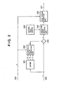
- Fig. 2 is a block diagram showing a conventional image processing apparatus.
- Fig. 2 shows an example of the apparatus which losslessly compresses an image in the above-described JPEG lossless coding mode.
- reference numeral 201 denotes a buffer; 202, a component value prediction unit; 203, a subtracter; 204, a Huffman table memory; 205, a prediction error encoding unit; 209, a code stream formation unit; and 206, 207, and 208, signal lines.
- the Huffman table memory 204 stores a Huffman table for use in the prediction error encoding unit 205. Assume that the Huffman table memory 204 stores a Huffman table shown in Fig. 6 .
- a prediction selection signal m for selecting a prediction method for use in the component value prediction unit 202 is input from the signal line 208.
- the prediction selection signal m takes an integer value of 0 to 7, and the respective values correspond to different prediction equations.
- the prediction selection signal m does not change and is fixed.
- Fig. 4 shows the correspondence between the prediction equation for use and the prediction selection signal m.
- the prediction selection signal m is 0, no prediction equation is defined. This means that each component is directly encoded without performing any predictive transform. Symbols "p", "a”, “b”, and “c” in Fig. 4 will be explained below.
- Image data are sequentially input from the signal line 206.
- the image data input order is the raster scan order, and component data of each pixel are input in the order of R, G, and B.
- the R, G, and B components are defined as component numbers of 0, 1, and 2, respectively.
- the buffer 201 has a capacity for storing image data of two lines that are input from the signal line 206.
- the component value prediction unit 202 generates a predicted value "p" in accordance with the prediction scheme selection signal m.
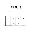
- Fig. 3 shows the positional relationship between "a”, “b", “c”, and the component value x of the pixel of interest. Note that when “a”, “b”, and “c" are outside an image, they are set to 0.
- the subtracter 203 calculates the difference value between the predicted value p and the component value x to be encoded, and outputs it as a prediction error e.
- the prediction error encoding unit 205 classifies prediction errors e input from the subtracter 203 into a plurality of groups, and generates a group number SSSS and overhead bits of a bit length defined for each group.
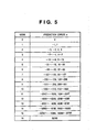
- Fig. 5 shows the relationship between the prediction error e and the group number SSSS.
- the MSB (Most Significant Bit) of overhead bits is 1 for a positive prediction error e and 0 for a negative prediction error e.
- encoded data corresponding to the group number SSSS is output by looking up the Huffman table stored in the Huffman table memory 204.
- SSSS is neither 0 nor 16
- overhead bits of a bit length defied by the group number are output.
- the code stream formation unit 209 forms a code stream of a format complying with the JPEG standard from encoded data output from the prediction error encoding unit 205, and additional information (e.g., the prediction selection signal m input via the signal line 208, the numbers of horizontal and vertical pixels of an image, the number of components which form a pixel, and the precision of each component).
- the code stream formation unit 209 outputs the code stream to the signal line 207.
- run-length encoding In addition to predictive encoding, run-length encoding is also known. According to run-length encoding, when a pixel of interest matches a previously encoded pixel, information representing the number of matched pixels is encoded. This encoding has high encoding efficiency when identical pixels run in an image.
- the purpose of encoding is to reduce the data amount of an original image, and that of lossless coding is to generate a code which can be completely decoded into an original image.
- losslessly coding it is more desirable to locally use the predictive encoding technique and run-length encoding technique than to apply only one of them.
- the present invention has been made in consideration of the above situation, and has as its object to provide a technique of efficiently coding data when encoding is executed selectively using encoding of each pixel and run-length coding.
- an image encoding apparatus according to an aspect of the present invention, as defined in claim 5.
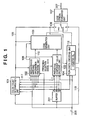
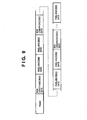
- Fig. 1 is a block diagram showing an image encoding apparatus according to the first embodiment.
- the image processing apparatus according to the first embodiment comprises a color count determination unit 101, neighborhood matching information encoding unit 102, predictive component value encoding unit 103, run-length encoding unit 104, code generation unit 105, switch 106, code stream formation unit 107, and buffer 201.
- reference numerals 108, 109, 110, 206, and 207 denote signal lines.
- the same reference numerals denote blocks which perform the same operations as those of the processing blocks of the conventional image processing apparatus, and a description thereof will be omitted.
- An image encoding process in the apparatus of Fig. 1 will be explained.
- the prediction selection signal m 4.
- Image data to be encoded by the image processing apparatus is image data of R, G, and B colors.
- Each component color component
- Each component is formed from pixel data which expresses a luminance value of 0 to 255 by 8 bits (multi-value).
- the first embodiment targets an RGB color image, but may be directed to an image having a plurality of components in one pixel (e.g., CMYK color image) or a monochrome multi-value image.
- Image data to be encoded has W horizontal pixels and H vertical pixels.
- Input image data has a data amount of W x H x 3 bytes.
- the horizontal right direction is defined as the positive direction of the X-coordinate
- the vertical down direction is defined as the positive direction of the Y-coordinate.
- the input order of input image data is the raster order, and each pixel is formed by laying out data in the order of R, G, and B.
- Image data to be encoded are sequentially input from the signal line 206, and stored in the buffer 201 (having a capacity of two lines).
- the input order of pixel data is the raster scan order, and component data of each pixel are input in the order of R, G, and B.
- the R, G, and B components are defined as component numbers of 0, 1, and 2, respectively.
- the upper left corner of an image is defined as coordinates (0,0), and the value of the component number C of a pixel at the horizontal right pixel position x and vertical lower pixel position y is represented by P(x,y,C).
- the color count determination unit 101 is made up of a color count calculation unit 101a, selector 101b, register 101c, and latch 101d. Details of the register 101c, latch 101d, and selector 101b will be described later. In the following description, the selector 101b selects data "a" and outputs it to the color count calculation unit 101a.
- the color count calculation unit 101a receives the values of the four surrounding pixels "a”, “b”, “c”, and “d” in Fig. 3 from the buffer 201, obtaining pixels Xa, Xb, Xc, and Xd.
- Xa P x ⁇ 1 , y , 0 , P x ⁇ 1 , y ⁇ 1 , P x ⁇ 1 , y , 2
- Xb P x , y ⁇ 1 , 0 , P x , y ⁇ 1 , 1 , P x , y ⁇ 1 , 2
- Xc P x ⁇ 1 , y ⁇ 1 , 0 , P x ⁇ 1 , y ⁇ 1 , 1 , P x ⁇ 1 , y ⁇ 1 , 2
- Xd P x + 1 , y ⁇ 1 , 0 , P x + 1 , y ⁇ 1 , 1 , P x + 1 , y ⁇ 1 , 2
- the color count calculation unit 101a detects the number of color types contained in the four pixels Xa, Xb, Xc, and Xd, and outputs a color count Nc onto the signal line 109. More specifically, the color count calculation unit 101a counts the number of extracted pairs having the same color among six pairs (Xa,Xb), (Xa,Xc), (Xa,Xd), (Xb,Xc), (Xb,Xd), and (Xc,Xd) each prepared by extracting two pixels from four pixels. The color count calculation unit 101a determines that there are four colors if the count is "0", three colors if "1", two colors if "2" or "3", and one color if "6". The color count calculation unit 101a outputs the color count Nc onto the signal line 109.
- the neighborhood matching information encoding unit 102 generates neighboring pixel state information and vector information on the basis of the color count Nc input via the signal line 109, the pixel X of interest, and the neighboring pixels Xa, Xb, Xc, and Xd.
- the neighborhood matching information encoding unit 102 outputs the neighboring pixel state information onto the signal line 108.
- the neighborhood matching information encoding unit 102 internally encodes the vector information, and outputs the code word onto the signal line 110.
- Fig. 11 is a block diagram showing in more detail the internal configuration of the neighborhood matching information encoding unit 102 in the embodiment.
- the neighborhood matching information encoding unit 102 is configured by a neighborhood matching determination unit 1101, matched-pixel position encoding unit 1102, and selector 1104.
- Reference numeral 1103 denotes a signal line. The reason that the selector 1104 is arranged will be described in detail later. In this description, the selector 1104 selects data "a".
- the neighborhood matching determination unit 1101 generates vector information for specifying whether a pixel having the same color as that of the pixel X of interest exists in four surrounding pixels (Xa, Xb, Xc, and Xd), and when the matched pixel exists, specifying the relative position of the pixel.
- the neighborhood matching determination unit 1101 outputs the vector information to the signal line 1103.
- the vector information is determined depending on the color count Nc input via the signal line 109. Processes by the neighborhood matching determination unit 1101 will be described for respective color counts Nc.
- the neighborhood matching determination unit 1101 When the color count Nc is 4, i.e., Xa, Xb, Xc, and Xd all have different pixel values, the neighborhood matching determination unit 1101 unconditionally outputs "4" as the vector information.
- the first pixel value (color) X1 and second pixel value X2 different from X1 are obtained in the order of Xa, Xb, Xc, and Xd.
- the first pixel X1 is Xa.
- the second pixel X2 is one of Xb, Xc, and Xd that has a value different from that of Xa.
- the first pixel value X1, second pixel value X2, and third pixel value X3 are obtained in the order of Xa, Xb, Xc, and Xd.
- the pixel X1 is Xa.
- the second pixel X2 is a pixel which does not match Xa for the first time in the order of Xb, Xc, and Xd.
- the pixel value X3 is a pixel which follows X2 and does not match X2.
- Neighboring pixel state information to be output from the neighborhood matching determination unit 1101 to the signal line 108 will be explained.
- Fig. 12 shows the relationship between the vector information and the neighboring pixel state information.
- the neighboring pixel state information is "0" when the color count Nc in four pixels near the pixel X of interest is three or less, and the four neighboring pixels contain at least one pixel having the same color as that of the pixel X of interest.
- the matched-pixel position encoding unit 1102 encodes the vector information input from the signal line 1103, and outputs a resultant code word to the signal line 110.
- the matched-pixel position encoding unit 1102 switches between the code tables in Figs. 15A to 15C and uses the selected one in accordance with the color count Nc.
- the color count Nc is 4, the matched-pixel position encoding unit 1102 does not output any code. Even if the matched-pixel position encoding unit 1102 outputs any code, the code is not employed as the code word of final image data, which will be described later.
- the code word of the vector information is output onto the signal line 110, and the neighboring pixel state information is output onto the signal line 108.
- the code generation unit 105 generates a code word to be output on the basis of the neighboring pixel state information (signal on the signal line 108) and the code word (signal on the signal line 110) of the vector information from the neighborhood matching information encoding unit 102, and a code word from the predictive component value encoding unit 103.
- the code generation unit 105 outputs the code word to the switch 106.
- the neighborhood matching information encoding unit 102 has already been described above, and the predictive component value encoding unit 103 will be explained.
- Predictive encoding of a component value can utilize a JPEG lossless encoding mode, or a scheme described as a regular mode in JPEG-LS (ITU-T T.87
- JPEG-LS ITU-T T.87
- Fig. 10 is a block diagram showing subblocks in the internal configuration of the predictive component value encoding unit 103.
- the predictive component value encoding unit 103 is made up of a component value prediction unit 202, subtracter 203, prediction error encoding unit 701, and selector 702.
- Reference numeral 108 denotes a signal line for inputting the above-described neighboring pixel state information. The reason that the selector 702 is arranged will be described later. In this description, the selector 702 selects data "a".
- the same reference numerals denote blocks which perform the same functions as those of processing blocks described in BACKGROUND OF THE INVENTION with reference to Fig. 2 , and a description thereof will be omitted.
- the component value prediction unit 202 generates a predicted value p from values "a”, "b", and "c" of pixels for each component around the pixel X of interest.
- a prediction selection signal m input to the component value prediction unit 202 is set to a fixed value "4", and all component values are predicted by an equation "a + b - c".
- the prediction error encoding unit 701 encodes the prediction error e by using Golomb encoding.
- Golomb encoding encodes a nonnegative integral value, and as its feature, can achieve encoding based on different probability models in accordance with a parameter variable k.
- Golomb encoding can derive a code word from a symbol to be encoded and the parameter variable k, and does not require any code table.
- One form of Golomb encoding is employed as a prediction error encoding scheme in JPEG-LS (ISO/IEC 14495-1
- the prediction error e output from the subtracter 203 is converted into a nonnegative integral value (defined as V) in accordance with the following equation, and V is Golomb-encoded by the selected parameter k:
- V is shifted to the right by k bits to obtain an integral value m.
- the code of V is formed from a combination of "1" (variable length part) following m "0"s and the lower k bits (fixed-length part) of V.
- the above-described code formation method is merely an example, and a uniquely decodable code can be formed even by replacing the fixed-length part and variable length part.
- the code can also be formed by replacing 0 and 1.
- As the method of selecting the encoding parameter k various methods are conceivable, including a method of selecting an optimal parameter k in a predetermined unit and integrating the parameter k into a code stream.
- the first embodiment adopts a method of updating the parameter k during encoding by the same method as JPEG-LS. The method of selecting the encoding parameter k will be described.
- the prediction error encoding unit 1001 comprises a counter N which holds the number of encoded pixels, and counters A[C] (C is a component number of 0 to 2) each of which holds the sum of the absolute values of encoded prediction errors for each component.
- the counter N is set to 1
- the counters A[0] to A[2] are set to 2.
- a maximum value k at which N x 2 ⁇ k does not exceed A[C] is obtained for each component value to be encoded.
- the prediction error e is Golomb-encoded by the above-described procedure using k, outputting a code word (note that x ⁇ y means y powers of x).
- k is updated by adding the absolute value
- N is incremented by one and updated after the encoding process of all components.
- a process of updating A[C] and N to 1/2 at the timing when N reaches a predetermined value (e.g., 32) is applied.
- the prediction error encoding unit 1001 operates only when neighboring pixel state information input via the signal line 108 is "1".
- the process contents of the predictive component value encoding unit 103 according to the first embodiment have been described.
- the code generation unit 105 will be explained.
- the code generation unit 105 receives four pieces of information: the predicted code words of R, G, and B components output from the predictive component value encoding unit 103, the code word of vector information and neighboring pixel state information which are output from the neighborhood matching information encoding unit 102, and the color count Nc. On the basis of these four pieces of information, the code generation unit 105 executes one of processes A to C.
- the code generation unit 105 When neighboring pixel state information is "0", i.e., the number of colors contained in four pixels near the pixel X of interest is three or less, as shown in Fig. 12 , and a pixel having the same color as that of the pixel X of interest exists in the four neighboring pixels, the code generation unit 105 outputs only the code word of input vector information.
- the code generation unit 105 outputs the predicted code words of R, G, and B components output from the predictive component value encoding unit 103, following the code word of input vector information.
- the code generation unit 105 outputs only the predicted code words of R, G, and B components output from the predictive component value encoding unit 103, and does not output the code word of vector information.
- Figs. 8A to 8C show code data output from the code generation unit 105.
- Fig. 8A shows the result of process A
- Fig. 8B shows that of process B
- Fig. 8C shows that of process C.
- the run-length encoding unit 104 holds a counter RL which counts the run of the same pixel value.
- the counter RL starts counting when the color count Nc of a pixel immediately before the pixel X of interest is a value other than "1" and the color count Nc of the pixel X of interest becomes "1". Once counting starts, the number of pixels is kept counted regardless of the color count Nc until the pixel X of interest has a color different from the immediately preceding pixel value Xa or the process of the final pixel on one line ends.
- the value held by the counter RL is run-length-encoded and output to the switch 106.
- the run-length encoding unit 104 outputs, to the switch 106 via a signal line 115, status information representing whether the counter RL is counting the run or does not count it.
- the run-length encoding unit 104 outputs information on this effect to a signal line 116 whose meaning will be described later.
- the run length can be encoded by various methods.
- the first embodiment employs the same method as run-length encoding using a run mode in the international standard JPEG-LS, and details thereof will be omitted.
- X i is defined as a pixel of interest; Nc i , as the color count of four pixels near the pixel X i of interest; S i-1 , as a pixel immediately before the pixel X i of interest; and Nc i-1 , as the color count of four pixels near the pixel X i-1 .
- Encoded data (encoded data in Fig. 8A or 8B ) output from the code generation unit 105 is called pixel-encoded data
- encoded data output from the run-length encoding unit 104 is called run length-encoded data, discriminating these encoded data.
- Status information output from the run-length encoding unit 104 onto the signal line 115 is "1" while the run is measured, and "0" when no run is measured. When status information is "0":
- the reason that the switch 106 is switched to the terminal b is that the run-length encoding unit 104 starts measuring the run under the above-described condition and no pixel-encoded data is output while the run is measured. Under a condition other than the above one, the switch 106 keeps selecting the terminal "a".
- the code stream formation unit outputs, as a header, additional information (e.g., the prediction selection signal m, the numbers of horizontal and vertical pixels of an image, the number of components which form a pixel, and the precision of each component).
- additional information e.g., the prediction selection signal m, the numbers of horizontal and vertical pixels of an image, the number of components which form a pixel, and the precision of each component.
- the code stream formation unit sequentially outputs encoded data input via the switch 106.
- the output destination is a storage device, the encoded data are output as a file.
- Fig. 9 shows the structure of encoded data output from the code stream formation unit 107.
- the order of run length-encoded data and pixel-encoded data is arbitrary.
- Fig. 9 shows that run length-encoded data and pixel-encoded data can coexist without any special break such as a marker.
- the prediction selection signal m is set to a fixed value, and may also be excluded from the header.
- the matched-pixel position encoding unit 1102 in the neighborhood matching information encoding unit 102 performs encoding using one of the encoding tables in Figs. 15A to 15C on the basis of the color count Nc.
- the matched-pixel position encoding unit 1102 may generate the code word of vector information using one table shown in Fig. 7 regardless of the color count Nc.
- the color count Nc 1
- the code word suffices to be formed from 1 bit regardless of whether the vector information is 0 or 1.
- a code word of 2 bits or more is generated, and the vector information encoding table is desirably switched in accordance with the color count Nc, as shown in Figs. 15A to 15C .
- the run by the run-length encoding unit 104 ends when the color of the pixel X of interest and that of the immediately preceding pixel Xa are different from each other. At this time, a value stored in the counter RL is run-length-encoded, the code word is output to the switch 106, and then pixel-encoded data of the pixel X of interest is output. As for the pixel X of interest, X ⁇ Xa, and vector information does not take "0", as is easily understood from Fig. 12 .
- the encoding efficiency becomes highest when data is formed from only the code word of vector information, as shown in Fig. 8A .
- the pixel Xf is desirably positioned near the pixel X of interest.
- the first embodiment adopts a pixel which is determined to be the end of the run in previous run-length encoding.
- the pixel X of interest which is determined to be the end of the run in the current run-length encoding is stored and held as the neighboring pixel Xf used when the run is determined to end in the next run-length encoding.
- Fig. 18 shows an example of an input image when the pixel X of interest ends run length-encoded data.
- Run length-encoded data immediately before the pixel X of interest shows a case wherein pixels having the same color as that of a pixel 1801 serving as the origin of the run continue and the color changes at the pixel X of interest.
- the color count determination unit 101 calculates again the color count Nc on the basis of the pixels "b", "c", and "d” near the pixel of interest, and pixel data "f" of the pixel 1802 instead of the pixel data "a".
- the neighborhood matching information encoding unit 102 encodes vector information, and generates neighboring pixel state information again.
- the predictive component value encoding unit 103 obtains the predicted value p on the basis of the pixel data "f", "b", and "c", and performs a prediction error encoding process for the pixel X of interest.
- the run-length encoding unit 104 outputs run end detection information onto the signal line 116 in order to hold data (R, G, and B component data) of the pixel X of interest at that time in the color count determination unit 101.
- a latch 101d in the color count determination unit 101 latches data of a register 101c, and outputs it as the pixel data "f" to a selector 101b, the neighborhood matching information encoding unit 102, and the predictive component value encoding unit 103.
- the register 101c overwrites (updates) previously stored/held data with data of the pixel X of interest at that time. That is, the register 101c holds the data of the pixel X of interest, and the latch 101d latches the pixel data f at which the run of the previous run-length code word ends.
- the selector 101b Upon reception of the run end detection information via the signal line 116, the selector 101b outputs data "f" instead of data "a” to the color count calculation unit 101a.
- the color count calculation unit calculates the color count Nc again on the basis of the pixels "b", “c", and “d” near the pixel X of interest and the pixel "f".
- the neighborhood matching information encoding unit 102 When the neighborhood matching information encoding unit 102 receives the run end detection information via the signal line 116, it causes the selector 1104 to select the pixel data f. The neighborhood matching information encoding unit 102 generates vector information again, encodes it again, outputs the encoded vector information to the signal line 110, and outputs again neighboring pixel state information to the signal line 108.
- the predictive component value encoding unit 103 when the predictive component value encoding unit 103 receives the run end detection information via the signal line 116, it causes the selector 702 to select the pixel data "f". The predictive component value encoding unit 103 calculates the predicted code word of the pixel of interest on the basis of the prediction selection signal and the component values of the data "f", "b", and "c".
- the switch 106 when the status signal output from the run-length encoding unit 104 onto the signal line 115 changes from "1" to "0", the switch 106 outputs run length-encoded data input from the run-length encoding unit 104.
- the switch 106 outputs the run length-encoded data to the code stream formation unit 107, and then outputs pixel-encoded data corresponding to the pixel X of interest that is generated by the color count determination unit 101, neighborhood matching information encoding unit 102, and predictive component value encoding unit 103 on the basis of the data "f" in place of the data "a".
- the image processing apparatus comprises the neighborhood matching information encoding unit 102, predictive component value encoding unit 103, and run-length encoding unit 104.
- the image processing apparatus executes encoding by switching the type of encoding method for these units in accordance with the number of colors present in the encoded pixels Xa, Xb, Xc, and Xd around the pixel X of interest to be encoded. In particular, switching between pixel-encoded data and run length-encoded data is determined in accordance with information on encoded pixel positions. Thus, encoded data does not require any special identification information representing that the type of encoding method is switched.
- the color count determination unit 101, neighborhood matching information encoding unit 102, and predictive component value encoding unit perform recalculation by temporarily referring to the pixel Xf at another position instead of the pixel data Xa which should be referred to in normal predictive encoding.
- a decrease in probability at which the format in Fig. 8A is adopted as the output format of pixel-encoded data can be suppressed, and higher compression efficiency can be expected.
- the process enters the run-length encoding mode because four surrounding pixels "a", "b", “c", and "d" have the same pixel value.
- the run ends at a length of 0, and the process shifts to encoding of vector information.
- the vector information is encoded by referring to the pixel Xf serving as the end of the immediately preceding run, and the possibility at which the pixel Xf matches the pixel X of interest rises, increasing the encoding efficiency.
- the first embodiment has been described on the basis of the configuration in Fig. 1 , but the same process as that of the first embodiment may also be implemented by a computer program.
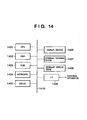
- Fig. 14 is a block diagram showing the basic configuration of an apparatus (PC or the like) when the apparatus is implemented by software.
- reference numeral 1401 denotes a CPU which controls the overall apparatus by using programs and data stored in a RAM 1402 and ROM 1403, and in addition, executes image encoding and decoding processes to be described later.
- the RAM 1402 is used to store programs and data which are downloaded from an external storage device 1407, a storage medium drive 1408, or an external apparatus via an I/F 1409.
- the RAM 1402 is also used as a work area when the CPU 1401 executes various processes.
- the buffer 201, Huffman table memory 204, and the like shown in Fig. 1 are also allocated in the RAM 1402.
- the ROM 1403 stores a boot program, apparatus setting programs, and data.
- Reference numerals 1404 and 1405 denote a keyboard and a pointing device (e.g., mouse), respectively, which allow the user to input various instructions to the CPU 1401.
- Reference numeral 1406 denotes a display device which is made up of a CRT, liquid crystal screen, and the like, and can display information such as an image and text.
- the external storage device 1407 is a large-capacity information storage device such as a hard disk drive.
- the external storage device 1407 saves an OS, programs for image encoding and decoding processes to be described later, image data to be encoded, encoded data of an image to be decoded, and the like. Programs and data are loaded into a predetermined area in the RAM 1402 under the control of the CPU 1401.
- the storage medium drive 1408 reads out programs and data which are recorded on a storage medium such as a CD-ROM or DVD-ROM, and outputs the readout programs and data to the RAM 1402 and external storage device 1407.
- the storage medium may record programs for image encoding and decoding processes to be described later, image data to be encoded, encoded data of an image to be decoded, and the like.
- the storage medium drive 1408 loads these programs and data to a predetermined area in the RAM 1402 under the control of the CPU 1401.
- the I/F 1409 connects an external apparatus to the image processing apparatus, and allows data communication between the image processing apparatus and the external apparatus.
- the I/F 1409 allows inputting image data to be encoded, encoded data of an image to be decoded, and the like to the RAM 1402, external storage device 1407, or storage medium drive 1408 of the apparatus.
- Reference numeral 1410 denotes a bus which connects the above units.
- Fig. 17 is a flowchart showing the flow of an encoding process by the image processing apparatus according to the modification. Note that a program complying with Fig. 17 is loaded into the RAM 1402 and executed by the CPU 1401 to achieve a process complying with the flowchart shown in Fig. 17 . The overall flow of the application program according to the modification will be explained with reference to Fig. 17 .
- the code stream formation unit 107 generates and outputs a header containing additional information of an image to be encoded (step S1901).
- a counter y which holds the vertical position of the pixel of interest is set to 0, the counter RL held in the run-length encoding unit 104 is initialized to 0, and the component values of the reference pixel Xf upon detection of the end of the run are initialized to "0" (step S1902).
- a counter x which holds the horizontal position of the pixel of interest is set to 0 (step S1903).
- the color count determination unit 101 obtains the color count Nc of pixels "a", "b", "c", and "d” around the pixel X of interest at coordinates (x,y) (step S1904).
- step S1906 the neighborhood matching information encoding unit 102 encodes vector information for the pixel of interest, and outputs the code word via the code generation unit 105.
- step S1907 determines whether neighboring pixel state information at the position of the pixel of interest is "1" (step S1907). If the neighboring pixel state information is "1" (YES in step S1907), the process advances to step S1923, and the predictive component value encoding unit 103 predictively encodes R, G, and B components.
- step S1909 the code word output from the code generation unit 105 and predictive component value encoding unit 103 is converted into a predetermined format by the code stream formation unit 107, forming a code stream for the pixel of interest (step S1909). Then, the counter x which holds the horizontal position of the pixel of interest is incremented by one (step S1910). The counter x is compared with the horizontal pixel count W of the image. If x ⁇ W (YES in step S1911), the process returns to step S1904 to perform the encoding process for the next pixel. If x ⁇ W (NO in step S1911), the process shifts to step S1912 (step S1911).
- step S1914 If X ⁇ Xa (NO in step S1914), the process advances to step S1920.
- step S1914 the counter RL held in the run-length encoding unit 104 is incremented by one (step S1915). Subsequently, the counter x which holds the horizontal position of the pixel of interest is incremented by one (step S1916). In step S1917, the counter x is compared with the horizontal pixel count W of the image. If x ⁇ W, the process returns to step S1914 to continue counting the next run. If x ⁇ W, the run reaches the right end of the image. At this time, the run length is finalized, and the run-length encoding unit 104 encodes the run length held by the counter RL, and outputs a code.
- the code output from the run-length encoding unit 104 is sent via the switch 106 to the code stream formation unit 107, which forms a code stream of a predetermined format (step S1918).
- the counter RL is reset to 0 (step S1919).
- the connection of the switch 106 is changed to the terminal "a”. The process shifts to step S1912, and the target of the encoding process shifts to the next line.
- step S1920 If the process advances from step S1914 to step S1920, this means that the run is terminated by the appearance of a pixel value X different from the immediately preceding pixel value Xa. Therefore, the run-length encoding unit 104 encodes the run length held by the counter RL, and outputs a code.
- the code word output from the run-length encoding unit 104 is sent via the switch 106 to the code stream formation unit 107, which forms a code stream of a predetermined format.
- the counter RL is reset to 0 (step S1921). At this time, data of the immediately preceding pixel Xa is replaced with the value of Xf (step S1701).
- step S1702 data of Xf is updated by data of the pixel X of interest.
- step S1703 the number of colors is calculated again on the basis of the pixels "f", “b”, “c”, and “d”, and the process advances to step S1906.
- the pixel data Xa is replaced with the pixel data Xf and the process is based on the pixels "f", "b", “c", and “d” after step S1906.
- pixel-encoded data of the pixel of interest is generated, and the connection of the switch 106 is changed to the terminal "a".
- step S1912 the counter y which holds the vertical position of the pixel of interest is incremented by one.
- the counter y is compared with the vertical pixel count H of the image. If y ⁇ H (YES in step S1913), the process returns to step S1903 to similarly process a pixel on the next line. If y ⁇ H (NO in step S1913), the encoding process for the target image ends (step S1913).
- a decoding process will be explained.
- the decoding process is basically paired with the encoding process.
- process procedures of decoding image data encoded by the above process will be explained with reference to the flowchart of Fig. 25 .
- none of reference pixels "a”, “b”, “c”, and “d” exists, and their components values are set to 0.
- step S2101 encoded data to be decoded is input to a code buffer (allocated in the RAM), and the header of the encoded data is analyzed to extract additional information necessary for decoding.
- the counter y which holds the vertical position of the pixel of interest is set to 0 (step S2102).
- R, G, and B data of the reference pixel Xf are initialized to 0, and a flag FLAG is initialized to "0" (step S2102).
- the flag FLAG is allocated in the RAM, and used to determine whether a run-length code word is decoded.
- step S2103 the counter x which holds the horizontal position of the pixel of interest is set to 0 (step S2103).
- step S2105 it is determined whether the color count Nc is "1". If the color count Nc is 1 (YES in step S2105), the process shifts to step S2114; if NO, to step S2110.
- step S2110 If it is determined in step S2110 that Nc ⁇ 4, the pixel of interest is the code word of vector information, and the code word is decoded into the vector information in step S2106. Decoding of the code word of the vector information uses a table corresponding to the number of colors, as shown in Figs. 15A to 15C .
- step S2107 If the obtained vector information coincides with the color count Nc, neighboring pixel state information "1" is generated; if they do not coincide with each other, "0" is generated. It is determined in step S2107 whether the neighboring pixel state information is "1" (see Fig. 12 ). When the neighboring pixel state information is "1”, encoded data of the pixel of interest has the data structure in Fig. 8B . When the neighboring pixel state information is "0”, encoded data of the pixel of interest has the data structure in Fig. 8A .
- the neighboring pixel state information is "1"
- the predicted code words of the components follow the code word of the vector information, and are decoded in step S2121.
- step S2109 the results of decoding the predictively encoded data of the components are output as data of the pixel of interest. If NO in step S2107, corresponding pixel data among the pixels "a”, “b”, “c”, and “d” is output as data of the pixel of interest in accordance with the decoded vector information.
- step S2105 If it is determined in step S2105 that the color count Nc is 1, the encoded data of interest is run length-encoded data, and the process advances to step S2114 to decode the run length RL. It should be noted that the decoding result may be "0" run.
- step S2115 If it is determined in step S2115 that RL ⁇ 0, Xa is output as a decoded pixel value (step S2116).
- the counter RL is decremented by one (step S2117), and the counter x which holds the horizontal position of the pixel of interest is incremented by one (step S2118).
- step S2119 the counter x is compared with the horizontal pixel count W. If x ⁇ W, the process returns to step S2115; if x ⁇ W, the process shifts to step S2112 (step S2119).
- step S2129 the flag FLAG is set to "1" in order to represent that the run-length code word has been decoded.
- the process advances to step S2130 to count the color count Nc on the basis of Xf, Xb, Xc, and Xd, and then returns to step S2110.
- step S2130 If the process returns from step S2130 to step S2110, the above-described process from step S2110 is performed to decode the pixel X of interest. After that, in step S2132, it is determined that the flag FLAG is "1".
- the pixel data Xf is updated with the decoded component values of the pixel X of interest in step S2133, and the flag FLAG is set to "0" in step S2134.
- step S2112 the counter y which holds the vertical position of the pixel of interest is incremented by one, and compared with the vertical pixel count H of the image. If y ⁇ H (YES in step S2113), the process returns to step S2103 to similarly process each pixel on the next line. If y ⁇ H (NO in step S2113), the decoding process for the target image data ends (step S2113).
- encoded data in the first embodiment can be losslessly decoded to reconstruct original image data.
- the second embodiment will explain an example of implementing this process by a computer program.
- the apparatus configuration is the same as that in Fig. 14 .
- FIG. 19 Process procedures are shown in the flowchart of Fig. 19 .
- a process of allocating and initializing the table is executed in, e.g., step S1902.
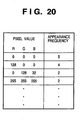
- Fig. 20 shows the state of the table when the encoding process proceeds to a certain stage. This table holds appearance color data in the descending order of the frequency. When a new color appears, color components representing the color are added and registered, and the appearance frequency is set to "1".
- step S1941 when the pixel X of interest ends the run.
- R, G, and B data having the highest frequency among pixels of colors that end previous runs are determined as data of the pixel Xf.
- step S1942 the frequency of the color data which determines the pixel Xf is incremented by "1" to update the table.
- the R, G, and B values of the pixel X of interest are added to the table, and the appearance frequency is set to "1".
- a pixel which most matches pixels of interest when a pixel that ends the run before the pixel of interest is encoded in accordance with neighborhood matching information is adopted as a reference pixel for the pixel of interest.
- the reference pixel and the pixel of interest are highly likely to match each other, and higher encoding efficiency can be expected.
- run length-encoded data in the third embodiment is used to generate the code word of the "run" itself and pixel-encoded data (one of data in Figs. 8A to 8C ) having a color at the origin of the run is always positioned immediately before the run length-encoded data, with one exception in which the pixel of interest is positioned at the start of each line of an image to be encoded.
- Fig. 21 In order to store a pixel immediately before a pixel serving as the origin of the run in performing run-length encoding, the process is executed in accordance with procedures shown in Fig. 21 .
- the flowchart in Fig. 21 is different from that in Fig. 17 in that two pixel data Xf and Xg are stored in a RAM 1402 and initialized to 0 (step S1902), and steps S1701 and S1702 are replaced with step S1952.
- the pixel data Xg is used to store and hold pixel data of the pixel X of interest
- Xf is used to store and hold one immediately preceding pixel data. Only processes different from those in Fig. 17 will be explained.
- step S1952 If the pixel X of interest ends the run, the pixel data Xa is temporarily replaced with the R, G, and B values of Xg, and the R, G, and B values of Xf are substituted into Xa in step S1952.
- the temporarily held values of Xg are substituted into Xf, and the R, G, and B values of the pixel X of interest are substituted into Xg. Consequently, only when the end pixel of the run is encoded, pixel data of the pixel X of interest and one immediately preceding pixel data are updated, and these values are always held.
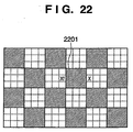
- the pixel X of interest is positioned as shown in Fig. 22 .
- a pixel 2201 in Fig. 22 is positioned at the end of the previous run and referred to, decreasing the encoding efficiency.
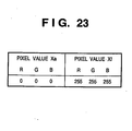
- the pixel Xf in Fig. 22 is referred to. It is understood that, when the R, G, and B values of the pixel X of interest are 255, 255, and 255, those of the reference pixel Xf become 255, 255, and 255, as shown in Fig. 23 , and the encoding efficiency increases.
- An image processing apparatus comprises a predictive encoding unit which obtains the predicted value of a pixel of interest on the basis of pixels (the number of pixels may be one) at encoded pixel positions near the pixel of interest, calculates the difference between the pixel value of interest and the predicted value, and encodes the difference value, and a run-length encoding unit which counts the run of the same pixel value, and when the run ends or the pixel of interest comes to the end of the line, encodes the count value.
- the predictive encoding unit and run-length encoding unit are properly switched.
- Image data to be encoded is image data of R, G, and B colors. Each component (color) is formed from pixel data which expresses a luminance value of 0 to 255 by 8 bits. Image data is formed by laying out pixels dot-sequentially, i.e., in the raster scan order, and each pixel is formed by laying out data in the order of R, G, and B. An image is made up of W horizontal pixels and H vertical pixels. Note that input image data is not limited to an RGB color image, and may be a CMY image (or CMYK image prepared by adding K) or a monochrome image.
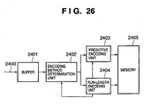
- Fig. 26 is a block diagram showing an image processing apparatus according to the comparative example.
- the image processing apparatus according to the comparative example comprises a buffer memory 2401 which temporarily stores image data to be encoded, an encoding method determination unit 2402, a predictive encoding unit 2403, a run-length encoding unit 2404, and a memory 2405 which stores encoded data.
- the encoding method determination unit 2402, predictive encoding unit 2403, and run-length encoding unit 2404 may be implemented by a program which runs on the computer. This configuration is identical to that shown in Fig. 14 .
- Image data are input from a signal line 2400 in the raster scan order.
- the buffer memory 2401 has an area enough to store image data of a plurality of lines, and temporarily stores image data input from the signal line 2400.
- the encoding method determination unit 2402 compares the pixel values Xa, Xb, Xc, and Xd of four encoded pixels "a", "b", “c", and "d” around a pixel X of interest, and determines whether the four surrounding pixels have the same pixel value. When the four surrounding pixels have the same pixel value, the encoding method determination unit 2402 selects the run-length encoding unit 2404 to start encoding. If the encoding method determination unit 2402 determines that the four surrounding pixels do not have the same pixel value, it selects the predictive encoding unit 2403 to perform encoding.
- the predictive encoding unit 2403 encodes the R, G, and B components of the pixel X of interest one by one.
- the run-length encoding unit 2404 starts measuring the run of pixels X of interest which match immediately preceding pixels. Once measurement of the run starts, the run-length encoding unit 2404 keeps measuring the run regardless of the states of four pixels around the pixel of interest as far as the pixel X of interest matches an immediately preceding pixel. When the pixel X of interest becomes different from an immediately preceding pixel or the pixel of interest comes to the end of the line (the end of the run is determined), the run-length encoding unit 2404 encodes the measured run, outputs the run length-encoded data to the memory 2405, and ends run-length encoding.
- run-length encoding unit 2404 When the run-length encoding unit 2404 outputs the run length-encoded data to the memory 2405, it notifies the encoding method determination unit 2402 of the end of run-length encoding. In response to this, encoding of the pixel of interest switches to that by the predictive encoding unit 2403.
- the difference value e from the pixel X of interest is obtained and predictively encoded.
- the encoding method determination unit 2402 is notified by the run-length encoding unit 2404 that run length-encoded data has been output, it stores and holds the pixel value of the pixel X of interest.
- the encoding method determination unit 2402 Upon reception of this notification, the encoding method determination unit 2402 outputs, to the predictive encoding unit 2403, the pixel value Xf which has been held in response to a previous notification, instead of the pixel values of "a", "b", and "c" for calculating a predicted value.
- the stored/held pixel X is a pixel immediately after the end of run-length encoding in the above description, but the present invention is not limited to this.
- another pixel which is referred to in predictive encoding to expect higher encoding efficiency such as a pixel immediately before the start of a pixel stream steam during run-length encoding, may be referred to.
- the value of another neighboring pixel is stored and held.
- another pixel is temporarily referred to instead of "a" which is one of surrounding pixels, but the number of alternative pixels is not limited to one.
- two other pixels may be temporarily referred to in place of the two pixels "a" and "b".
- the average of two other pixels may be calculated instead of "a" which is one of surrounding pixels.
- the pixel value Xa of a pixel immediately before the pixel X of interest may be stored as Xf.
- the predicted value p is calculated using another pixel value near a portion having undergone run-length encoding or near a portion during run-length encoding.
- the difference value e between the predicted value p and the pixel of interest is obtained and predictively encoded.
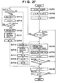
- step S2701 a header is generated and output in generating encoded data.
- step S2702 a variable y representing the vertical position of the pixel of interest is initialized to "0".
- a counter variable RL which counts the run is initialized to "0"
- a variable Xf which holds a predicted value used immediately after switching from run-length encoding to predictive encoding is initialized to "0”.
- step S2703 a variable x representing the horizontal position of the pixel of interest is initialized to "0".
- step S2704 it is determined whether the pixel values Xa, Xb, Xc, and Xd of four pixels around the pixel X of interest represented by coordinates (x,y) are equal. If it is determined that the pixel values Xa, Xb, Xc, and Xd are different, the process advances to step S2705 to predictively encode each component. In step S2706, the encoding result is output. As described above, when a surrounding pixel is outside an image to be encoded, each component value of the pixel is set to 0.
- step S2707 the variable x is incremented by "1".
- step S2708 the value of the variable x is compared with the number W of horizontal pixels of an input image to determine whether the pixel of interest exceeds the end of one line. If x ⁇ W is determined, the process from step S2704 is repeated; if x ⁇ W is determined, the variable y is incremented by "1" in step S2709 in order to encode the next line.
- step S2710 the variable y is compared with the number H of vertical pixels of the input image to determine whether encoding of the final line is completed. If y ⁇ H is determined, the process from step S2703 is repeated; if y ⁇ H is determined, the encoding process ends.
- step S2704 If it is determined in step S2704 during the process that four encoded pixels around the pixel X of interest have the same pixel value, the process advances to step S2711 in order to switch the above-described predictive encoding process to run-length encoding.
- step S2711 it is determined whether the pixel X of interest and the immediately preceding pixel Xa are identical. If it is determined that the pixel X of interest and the immediately preceding pixel Xa are identical, the counter variable RL is incremented by "1" in step S2712. In step S2713, the variable x is also incremented by "1" in order to set the next pixel as the pixel of interest. After that, whether "x ⁇ W" is determined in step S2714. If x ⁇ W is determined, the process from step S2711 is repeated.
- step S2711 If the pixel X of interest is different from the immediately preceding pixel Xa, the run ends, and the process advances from step S2711 to step S2715 to encode the value of the counter variable RL.
- the encoding result is output in step S2716, and the counter RL is initialized to "0" in step S2717.
- Xf is set instead of Xa so as to calculate the predicted value p. Accordingly, the predicted value p is given by Xf + Xb - Xc.
- step S2719 the value of the pixel X of interest is substituted into f in order to hold a predicted value immediately after the next run-length encoding switches to predictive encoding. Then, the process advances to step S2705. It should be noted that when the process advances to step S2705, the predicted value p for the pixel X of interest utilizes Xf + Xb - Xc.
- step S2714 If x ⁇ W is determined in step S2714, this means that the position of the pixel X of interest exceeds the end of one line. Thus, the process advances to step S2720 to encode the value of the counter variable RL. The encoding result is output in step S2721, the counter variable RL is reset to "0" in step S2722, and the process advances to step S2709.
- encoded data can be successfully generated by appropriately switching between the predictive encoding process and the run-length encoding process.
- a pixel value at a position immediately before the pixel of interest but a pixel value serving as the end of the run in previous run-length encoding is used as a predicted value in predictive encoding. This can also suppress a decrease in encoding efficiency.
- image data to be encoded is data of R, G, and B components each by 8 bits.
- data representing the color space is not limited to R, G, and B, but may be Y, M, C, and K (blacK), L*a*b*, or YCbCr.
- Each component value need not always be an 8-bit value.
- some recent digital cameras and the like internally process R, G, and B by 12 bits, and losslessly encode the data in the RAW mode.
- the present invention can also be applied to such an apparatus.
- matches/mismatches with Nc pixel values are encoded in accordance with the color count Nc of surrounding pixels.
- a symbol of Nc + 1 is encoded.
- the symbols of four values are encoded using the code table in Fig. 15C such that when the color count Nc is 3, the symbol is 0 if the pixel of interest matches the first pixel value X1; 1 if the pixel of interest matches the second pixel value X2; 2 if the pixel of interest matches the third pixel value X3; and 3 if the pixel of interest does not match any of X1 to X3.
- not all Nc pixel values need be subjected to match/mismatch determination.
- the method of obtaining the first, second, and third pixel values X1, X2, and X3 is not limited to the above-described embodiments.
- the first, second, and third pixel values may be acquired in the order of Xb, Xa, Xc, and Xd, which is different from the above-described one.
- the order may be changed in accordance with matching between Xa, Xb, Xc, and Xd.
- the first, second, and third pixel values are acquired in the order of Xa, Xb, Xc, and Xd.
- Xa Xb
- Xd may be set as the second pixel value X2.
- Encoding of vector information may use a code word which is set in advance on the assumption of the probability distribution. However, a code word different from those in the above examples may be used, or a different encoding scheme such as a scheme using an arithmetic code may be applied.
- nonlinear prediction may be used to feed back the average value of prediction errors generated in encoded component values to prediction of the component of interest.
- the above embodiments employ Huffman encoding and Golomb encoding as entropy encoding of the prediction error of a component value.
- Another entropy encoding may also be adopted.
- Xa, Xb, Xc, and Xd are referred to.
- a larger number of pixels may be referred to, or the number of reference pixels may be decreased to, e.g., only Xa and Xb.
- the present invention can also be implemented by a computer program which is executed by a computer.
- the computer program is stored in a computer-readable storage medium such as a CD-ROM, and can be executed by copying or installing the program in the system using a reading device such as a drive which accesses the storage medium.
- the computer program apparently falls within the scope of the present invention.
- data can be efficiently encoded while both encoding of each pixel and run-length encoding of encoding the run of pixels are utilized.
- the present disclosure teaches that image data is efficiently encoded using a predict coding unit and a run-length coding unit.
- the predict coding unit encodes a target pixel X on the basis of difference between the value of the target pixel and a predict value calculated from pixels neighboring the target pixel.
- the run-length coding unit starts the measuring the run when the number of colors contained in four pixels "a", "b", "c", and "d" near the target pixel X is 1. and outputs encoded data of the run when the target pixel is different from an immediately preceding pixel "a”. Then, the predict coding unit starts the encoding.
- the preceding pixel is excluded from references for generating the predict value. Instead of the preceding pixel, an pixel, which has been encoded, satisfying a specific condition is referred to.
Landscapes
- Engineering & Computer Science (AREA)
- Multimedia (AREA)
- Signal Processing (AREA)
- Physics & Mathematics (AREA)
- General Physics & Mathematics (AREA)
- Theoretical Computer Science (AREA)
- Compression Or Coding Systems Of Tv Signals (AREA)
- Compression Of Band Width Or Redundancy In Fax (AREA)
Claims (8)
- Bildkodierungsvorrichtung zum Kodieren von Bilddaten, mit:einer ersten Kodierungseinheit (103), die angepasst ist zum Kodieren eines Pixelwerts eines Zielpixels durch Verwendung eines Pixelwerts eines Pixels, das dem Zielpixel vorausgehend kodiert wurde;einer zweiten Kodierungseinheit (104), die angepasst ist zum Zählen einer Anzahl von Pixel mit dem gleichen Wert als Lauf, Beenden der Zählung und Ausgeben von kodierten Daten basierend auf dem gezählten Lauf, wenn das Zielpixel ein Lauf-beendendes Pixel mit einem unterschiedlichen Wert gegenüber dem unmittelbar vorhergehenden Pixel ist; undeiner Schalteinheit (106), die angepasst ist zum Umschalten zwischen einer Kodierung durch die erste Kodierungseinheit und einer Kodierung durch die zweite Kodierungseinheit,dadurch gekennzeichnet, dassdie Schalteinheit angepasst ist zum Bewirken, dass, nachdem die zweite Kodierungseinheit kodierte Daten ausgibt, die erste Kodierungseinheit eine Kodierung des Zielpixels beginnt, das als das Lauf-beendende Pixel bestimmt ist, undwenn die Schalteinheit von der zweiten Kodierungseinheit auf die erste Kodierungseinheit umschaltet, das Zielpixel als das Lauf-beendende Pixel bestimmt wird, und die erste Kodierungseinheit angepasst ist zum Kodieren des Zielpixels unter Verwendung eines Werts eines Pixels, das kodiert wurde, wobei dieses von dem dem Zielpixel untermittelbar vorhergehenden Pixel verschieden ist, und wobei dieses als das Lauf-beendende Pixel eines vorangehenden Laufs der zweiten Kodierungseinheit bestimmt ist.
- Vorrichtung gemäß Anspruch 1, wobei das Pixel, das durch die erste Kodierungseinheit zu verwenden ist, wenn die Schalteinheit von der zweiten Kodierungseinheit auf die erste Kodierungseinheit umschaltet, was dadurch bewirkt wird, dass das Zielpixel als das Lauf-beendende Pixel bestimmt ist, ein Pixel ist, das als das Lauf-beendende Pixel des Laufs bestimmt ist, der dem unmittelbar vorausgehenden Lauf der zweiten Kodierungseinheit vorangeht, wobei der unmittelbar vorausgehende Lauf der zweiten Kodierungseinheit der Lauf unmittelbar vor dem Zielpixel ist.
- Vorrichtung gemäß Anspruch 1, wobei das Pixel, das durch die erste Kodierungseinheit zu verwenden ist, wenn die Schalteinheit von der zweiten Kodierungseinheit auf die erste Kodierungseinheit umschaltet, was dadurch bewirkt wird, dass das Zielpixel als das Lauf-beendende Pixel bestimmt ist, ein häufigstes Pixel unter Pixel ist, die als Lauf-beendende Pixel von vorangehenden Läufen der zweiten Kodierungseinheit bestimmt sind.
- Bildkodierungsverfahren zum Kodieren von Bilddaten, mit:einem ersten Kodierungsschritt des Kodierens eines Pixelwerts eines Zielpixels durch Verwendung eines Pixelwerts eines Pixels, das dem Zielpixel vorausgehend kodiert wurde;einem zweiten Kodierungsschritt des Zählens einer Anzahl von Pixel mit dem gleichen Wert als Lauf, Beenden der Zählung und Ausgeben von kodierten Daten basierend auf dem gezählten Lauf, wenn das Zielpixel ein Lauf-beendendes Pixel mit einem unterschiedlichen Wert gegenüber dem unmittelbar vorhergehenden Pixel ist; undeinem Schaltschritt des Umschaltens zwischen einer Kodierung in dem ersten Kodierungsschritt und einer Kodierung in dem zweiten Kodierungsschritt,dadurch gekennzeichnet, dassder Schaltschritt bewirkt, dass, nachdem der zweite Kodierungsschritt kodierte Daten ausgibt, der erste Kodierungsschritt eine Kodierung des Zielpixels beginnt, das als das Lauf-beendende Pixel bestimmt ist, undwenn der Schaltschritt von dem zweiten Kodierungsschritt auf den ersten Kodierungsschritt umschaltet, das Zielpixel als das Lauf-beendende Pixel bestimmt wird, und der erste Kodierungsschritt das Zielpixel unter Verwendung eines Werts eines Pixels kodiert, das kodiert wurde, wobei dieses von dem dem Zielpixel unmittelbar vorhergehenden Pixel verschieden ist, und wobei dieses als das Lauf-beendende Pixel eines vorangehenden Laufs des zweiten Kodierungsschritts bestimmt ist.
- Bildkodierungsvorrichtung zum Kodieren von Bilddaten, mit:einer ersten Kodierungseinheit (103), die angepasst ist zum Kodieren eines Pixelwerts eines Zielpixels durch Verwendung eines Pixelwerts eines Pixels, das dem Zielpixel vorausgehend kodiert wurde;einer zweiten Kodierungseinheit (104), die angepasst ist zum Zählen einer Anzahl von Pixel mit dem gleichen Wert als Lauf, Beenden der Zählung und Ausgeben von kodierten Daten basierend auf dem gezählten Lauf, wenn das Zielpixel ein Lauf-beendendes Pixel mit einem unterschiedlichen Wert gegenüber dem unmittelbar vorhergehenden Pixel ist; undeiner Schalteinheit (106), die angepasst ist zum Umschalten zwischen einer Kodierung durch die erste Kodierungseinheit und einer Kodierung durch die zweite Kodierungseinheit,dadurch gekennzeichnet, dassdie Schalteinheit angepasst ist zum Bewirken, dass, nachdem die zweite Kodierungseinheit kodierte Daten ausgibt, die erste Kodierungseinheit eine Kodierung des Zielpixels beginnt, das als das Lauf-beendende Pixel bestimmt ist, undwenn die Schalteinheit von der zweiten Kodierungseinheit auf die erste Kodierungseinheit umschaltet, das Zielpixel als das Lauf-beendende Pixel bestimmt wird, und die erste Kodierungseinheit angepasst ist zum Kodieren des Zielpixels unter Verwendung eines Werts eines Pixels, das kodiert wurde, wobei dieses von dem dem Zielpixel untermittelbar vorhergehenden Pixel verschieden ist, und wobei dieses ein Pixel unmittelbar vor dem Startpixel des unmittelbar vorhergehenden Laufs der zweiten Kodierungseinheit ist, wobei der unmittelbar vorhergehende Lauf der zweiten Kodierungseinheit der Lauf unmittelbar vor dem Zielpixel ist.
- Bildkodierungsverfahren zum Kodieren von Bilddaten, mit:einem ersten Kodierungsschritt des Kodierens eines Pixelwerts eines Zielpixels durch Verwendung eines Pixelwerts eines Pixels, das dem Zielpixel vorausgehend kodiert wurde;einem zweiten Kodierungsschritt des Zählens einer Anzahl von Pixel mit dem gleichen Wert als Lauf, Beenden der Zählung und Ausgeben von kodierten Daten basierend auf dem gezählten Lauf, wenn das Zielpixel ein Lauf-beendendes Pixel mit einem unterschiedlichen Wert gegenüber dem unmittelbar vorhergehenden Pixel ist; undeinem Schaltschritt des Umschaltens zwischen einer Kodierung in dem ersten Kodierungsschritt und einer Kodierung in dem zweiten Kodierungsschritt,dadurch gekennzeichnet, dassder Schaltschritt bewirkt, dass, nachdem der zweite Kodierungsschritt kodierte Daten ausgibt, der erste Kodierungsschritt eine Kodierung des Zielpixels beginnt, das als das Lauf-beendende Pixel bestimmt ist, undwenn der Schaltschritt von dem zweiten Kodierungsschritt auf den ersten Kodierungsschritt umschaltet, das Zielpixel als das Lauf-beendende Pixel bestimmt wird, und der erste Kodierungsschritt das Zielpixel unter Verwendung eines Werts eines Pixels kodiert, das kodiert wurde, wobei dieses von dem dem Zielpixel unmittelbar vorhergehenden Pixel verschieden ist, und wobei dieses ein Pixel unmittelbar vor dem Startpixel des unmittelbar vorhergehenden Laufs des zweiten Kodierungsschritt ist, wobei der unmittelbar vorhergehende Lauf des zweiten Kodierungsschritts der Lauf unmittelbar vor dem Zielpixel ist.
- Computerlesbares Speichermedium, das ein Computerprogramm speichert, das zum Bewirken dient, dass ein Computer die Schritte des Verfahrens gemäß Anspruch 4 oder 6 ausführt.
- Computerprogramm zum Bewirken, dass ein Computer die Schritte des Verfahrens gemäß Anspruch 4 oder 6 ausführt.
Applications Claiming Priority (1)
| Application Number | Priority Date | Filing Date | Title |
|---|---|---|---|
| JP2005146984A JP4587175B2 (ja) | 2005-05-19 | 2005-05-19 | 画像符号化装置及び方法、並びに、コンピュータプログラム及びコンピュータ可読記憶媒体 |
Publications (3)
| Publication Number | Publication Date |
|---|---|
| EP1725040A2 EP1725040A2 (de) | 2006-11-22 |
| EP1725040A3 EP1725040A3 (de) | 2010-12-08 |
| EP1725040B1 true EP1725040B1 (de) | 2016-08-03 |
Family
ID=36952431
Family Applications (1)
| Application Number | Title | Priority Date | Filing Date |
|---|---|---|---|
| EP06113210.6A Expired - Fee Related EP1725040B1 (de) | 2005-05-19 | 2006-04-27 | Vorrichtung und Verfahren zur Bildkodierung, Computerprogramm und computerlesbares Speichermedium |
Country Status (5)
| Country | Link |
|---|---|
| US (1) | US7689048B2 (de) |
| EP (1) | EP1725040B1 (de) |
| JP (1) | JP4587175B2 (de) |
| KR (1) | KR100819992B1 (de) |
| CN (1) | CN100484250C (de) |
Families Citing this family (18)
| Publication number | Priority date | Publication date | Assignee | Title |
|---|---|---|---|---|
| US7650039B2 (en) | 2005-03-03 | 2010-01-19 | Canon Kabushiki Kaisha | Image encoding apparatus, image decoding apparatus, control method therefor, computer program, and computer-readable storage medium |
| JP4732203B2 (ja) * | 2006-03-17 | 2011-07-27 | キヤノン株式会社 | 画像符号化装置及び復号装置及びそれらの制御方法、並びに、コンピュータプログラム及びコンピュータ可読記憶媒体 |
| CN101438597B (zh) * | 2006-05-17 | 2011-05-11 | 富士通株式会社 | 图像数据压缩装置、压缩方法、图像数据恢复装置、恢复方法 |
| JP4795161B2 (ja) * | 2006-08-08 | 2011-10-19 | キヤノン株式会社 | 画像処理装置及びその制御方法、並びに、コンピュータプログラム及びコンピュータ可読記憶媒体 |
| EP1978749B1 (de) * | 2007-04-06 | 2017-08-30 | Canon Kabushiki Kaisha | Kompression mehrdimensionaler Nachschlagetabellen zur Farbenraumumwandlung |
| JP4847398B2 (ja) * | 2007-06-06 | 2011-12-28 | キヤノン株式会社 | 画像処理装置およびその方法 |
| JP4979655B2 (ja) * | 2008-08-07 | 2012-07-18 | キヤノン株式会社 | 画像符号化装置及びその制御方法 |
| JP2010136181A (ja) * | 2008-12-05 | 2010-06-17 | Sony Corp | 画像処理装置、画像処理方法およびプログラム |
| JP4748234B2 (ja) * | 2009-03-05 | 2011-08-17 | 富士ゼロックス株式会社 | 画像処理装置および画像形成装置 |
| JP5369982B2 (ja) * | 2009-08-06 | 2013-12-18 | 株式会社リコー | 画像処理装置および画像処理方法 |
| US20110292247A1 (en) * | 2010-05-27 | 2011-12-01 | Sony Corporation | Image compression method with random access capability |
| US8968080B1 (en) | 2010-11-05 | 2015-03-03 | Wms Gaming, Inc. | Display of third party content on a wagering game machine |
| SG2013016456A (en) * | 2013-01-11 | 2014-08-28 | Brainwave Innovations Private Ltd | Image compression and lossless reconstruction of digital image |
| JP2015023506A (ja) * | 2013-07-22 | 2015-02-02 | 株式会社東芝 | 画像符号化装置及び画像復号化装置 |
| US9160363B2 (en) * | 2014-02-27 | 2015-10-13 | Samsung Display Co., Ltd. | Run length encoding with non-sequential input |
| CN109788290A (zh) * | 2017-11-13 | 2019-05-21 | 慧荣科技股份有限公司 | 影像处理装置及利用帧内预测的无损影像压缩方法 |
| CN108419080B (zh) * | 2018-02-08 | 2020-10-13 | 武汉精测电子集团股份有限公司 | 一种jpegls上下文计算的流水线化优化方法及装置 |
| CN110636308B (zh) * | 2019-09-21 | 2022-05-10 | 苏州维赛智芯体育科技有限公司 | 一种基于改进型游程编码的线阵图像数据压缩方法 |
Family Cites Families (37)
| Publication number | Priority date | Publication date | Assignee | Title |
|---|---|---|---|---|
| NL8601182A (nl) * | 1986-05-12 | 1987-12-01 | Philips Nv | Werkwijze en inrichting voor het opnemen en/of weergeven van een beeldsignaal en een bijbehorend audiosignaal in respektievelijk van een registratiedrager, en een registratiedrager verkregen volgens de werkwijze. |
| JPH0651721A (ja) | 1992-07-29 | 1994-02-25 | Canon Inc | 表示制御装置 |
| US5650829A (en) * | 1994-04-21 | 1997-07-22 | Sanyo Electric Co., Ltd. | Motion video coding systems with motion vector detection |
| JPH08130649A (ja) | 1994-11-01 | 1996-05-21 | Canon Inc | データ処理装置 |
| US6031938A (en) | 1995-04-26 | 2000-02-29 | Canon Kabushiki Kaisha | Image encoding apparatus with selective Markov and predictive coding |
| US6101282A (en) | 1995-06-22 | 2000-08-08 | Canon Kabushiki Kaisha | Apparatus and method for image data encoding |
| US6028963A (en) | 1996-06-17 | 2000-02-22 | Canon Kabushiki Kaisha | Image encoding based on judgement on prediction error |
| DE69736661D1 (de) * | 1997-01-31 | 2006-10-26 | Victor Company Of Japan | Vorrichtung zur Videocodierung und -decodierung mit Bewegungskompensation |
| JPH10336682A (ja) | 1997-04-02 | 1998-12-18 | Canon Inc | 符号化装置及び方法及び方法を記憶した記憶媒体 |
| JPH11234683A (ja) * | 1998-02-12 | 1999-08-27 | Fuji Xerox Co Ltd | 画像符号化方法および装置 |
| JPH11243491A (ja) * | 1998-02-26 | 1999-09-07 | Agency Of Ind Science & Technol | 適応進化型画像圧縮符号化装置 |
| JP2000069292A (ja) | 1998-08-24 | 2000-03-03 | Canon Inc | 画像処理装置及び方法及び記憶媒体 |
| JP3839974B2 (ja) | 1998-10-06 | 2006-11-01 | キヤノン株式会社 | 符号化装置 |
| JP2000115782A (ja) | 1998-10-06 | 2000-04-21 | Canon Inc | 符号化装置及び方法及び記憶媒体 |
| JP2000115783A (ja) | 1998-10-06 | 2000-04-21 | Canon Inc | 復号化装置及び方法 |
| US6665444B1 (en) | 1999-04-28 | 2003-12-16 | Canon Kabushiki Kaisha | Image processing apparatus and method, and storage medium |
| KR100379383B1 (ko) * | 1999-11-03 | 2003-04-10 | 엘지전자 주식회사 | 인트라 프레임 부호화 방법 |
| JP4365957B2 (ja) | 1999-11-05 | 2009-11-18 | キヤノン株式会社 | 画像処理方法及びその装置及び記憶媒体 |
| JP4367880B2 (ja) | 1999-12-09 | 2009-11-18 | キヤノン株式会社 | 画像処理装置及びその方法並びに記憶媒体 |
| JP2002281444A (ja) | 2000-03-03 | 2002-09-27 | Canon Inc | 画像処理方法及び装置及び記憶媒体 |
| JP4208378B2 (ja) | 2000-03-10 | 2009-01-14 | キヤノン株式会社 | 画像処理装置及び方法及び記録媒体 |
| JP4480119B2 (ja) | 2000-03-30 | 2010-06-16 | キヤノン株式会社 | 画像処理装置及び画像処理方法 |
| US6847735B2 (en) | 2000-06-07 | 2005-01-25 | Canon Kabushiki Kaisha | Image processing system, image processing apparatus, image input apparatus, image output apparatus and method, and storage medium |
| JP4612782B2 (ja) | 2000-09-27 | 2011-01-12 | キヤノン株式会社 | 画像処理装置、及びその方法、並びにプログラム、記憶媒体 |
| US7013050B2 (en) | 2001-06-26 | 2006-03-14 | Canon Kabushiki Kaisha | Image encoding apparatus and method, program code, and storage medium |
| JP3984886B2 (ja) | 2001-09-28 | 2007-10-03 | キヤノン株式会社 | データ変換装置、データ変換方法、コンピュータプログラム、記憶媒体 |
| US7302105B2 (en) | 2002-07-22 | 2007-11-27 | Canon Kabushiki Kaisha | Moving image coding apparatus, moving image decoding apparatus, and methods therefor |
| US7903734B2 (en) | 2003-04-24 | 2011-03-08 | Canon Kabushiki Kaisha | Moving image decoding apparatus, moving image decoding method, image decoding method, and image decoding apparatus |
| US7177479B2 (en) * | 2003-04-25 | 2007-02-13 | Stmicroelectronics S.R.L. | Loss-less compression of still images at enhanced speed |
| US7574063B2 (en) | 2003-07-23 | 2009-08-11 | Canon Kabushiki Kaisha | Image coding method and apparatus |
| JP4702928B2 (ja) | 2004-03-12 | 2011-06-15 | キヤノン株式会社 | 動画像符号化装置及び復号装置及びその制御方法、並びにコンピュータプログラム及びコンピュータ可読記憶媒体 |
| JP4418762B2 (ja) | 2004-05-07 | 2010-02-24 | キヤノン株式会社 | 画像符号化装置及び画像復号装置及びそれらの制御方法、並びに、コンピュータプログラム及びコンピュータ可読記憶媒体 |
| US20080089413A1 (en) | 2004-06-28 | 2008-04-17 | Canon Kabushiki Kaisha | Moving Image Encoding Apparatus And Moving Image Encoding Method |
| US7529417B2 (en) | 2004-07-09 | 2009-05-05 | Canon Kabushiki Kaisha | Apparatus, method and storage medium for image encoding/decoding using shape-based coefficient interpolation |
| JP4533043B2 (ja) | 2004-08-25 | 2010-08-25 | キヤノン株式会社 | 画像符号化装置及び方法、並びに、コンピュータプログラム及びコンピュータ可読記憶媒体 |
| US7650039B2 (en) | 2005-03-03 | 2010-01-19 | Canon Kabushiki Kaisha | Image encoding apparatus, image decoding apparatus, control method therefor, computer program, and computer-readable storage medium |
| JP4732203B2 (ja) | 2006-03-17 | 2011-07-27 | キヤノン株式会社 | 画像符号化装置及び復号装置及びそれらの制御方法、並びに、コンピュータプログラム及びコンピュータ可読記憶媒体 |
-
2005
- 2005-05-19 JP JP2005146984A patent/JP4587175B2/ja not_active Expired - Fee Related
-
2006
- 2006-04-27 EP EP06113210.6A patent/EP1725040B1/de not_active Expired - Fee Related
- 2006-05-02 US US11/415,079 patent/US7689048B2/en not_active Expired - Fee Related
- 2006-05-19 CN CNB2006100824505A patent/CN100484250C/zh not_active Expired - Fee Related
- 2006-05-19 KR KR20060045009A patent/KR100819992B1/ko active IP Right Grant
Non-Patent Citations (1)
| Title |
|---|
| LIH-JEN KAU ET AL: "Lossless image coding using a switching predictor with run-length encodings", 2004 IEEE INTERNATIONAL CONFERENCE ON MULTIMEDIA AND EXPO : JUNE 27 - 30, 2004, TAIPEI, TAIWAN, IEEE OPERATIONS CENTER, PISCATAWAY, NJ, vol. 2, 27 June 2004 (2004-06-27), pages 1155 - 1158, XP010771029, ISBN: 978-0-7803-8603-7, DOI: 10.1109/ICME.2004.1394422 * |
Also Published As
| Publication number | Publication date |
|---|---|
| CN1867077A (zh) | 2006-11-22 |
| US20060262982A1 (en) | 2006-11-23 |
| JP4587175B2 (ja) | 2010-11-24 |
| KR100819992B1 (ko) | 2008-04-07 |
| US7689048B2 (en) | 2010-03-30 |
| CN100484250C (zh) | 2009-04-29 |
| KR20060120478A (ko) | 2006-11-27 |
| JP2006325006A (ja) | 2006-11-30 |
| EP1725040A2 (de) | 2006-11-22 |
| EP1725040A3 (de) | 2010-12-08 |
Similar Documents
| Publication | Publication Date | Title |
|---|---|---|
| EP1725040B1 (de) | Vorrichtung und Verfahren zur Bildkodierung, Computerprogramm und computerlesbares Speichermedium | |
| US7650039B2 (en) | Image encoding apparatus, image decoding apparatus, control method therefor, computer program, and computer-readable storage medium | |
| US20210092445A1 (en) | Method for Producing Video Coding and Programme-Product | |
| US7783119B2 (en) | Image encoding apparatus, image decoding apparatus and control method therefor | |
| JP3839974B2 (ja) | 符号化装置 | |
| US11425386B2 (en) | Method and apparatus for range derivation in context adaptive binary arithmetic coding | |
| JP4956304B2 (ja) | 画像符号化装置及びその制御方法、並びに、コンピュータプログラム及びコンピュータ可読記憶媒体 | |
| US10609393B2 (en) | Image encoding apparatus and method of controlling the same | |
| WO2018127167A1 (en) | Method and apparatus for range derivation in context adaptive binary arithmetic coding | |
| JP2019110530A (ja) | ビデオデータを符号化するための方法及び装置 | |
| CN107277529B (zh) | 图像解码装置、图像解码方法、接收装置 | |
| JP2019110529A (ja) | ビデオデータを符号化するための方法及び装置 | |
| JP3085932B2 (ja) | マスクを用いた予測映像発生装置及びその装置を用いた2進映像の圧縮、伝送及び復元装置 | |
| JP4343863B2 (ja) | 画像符号化装置及び画像復号装置、並びに、それらの制御方法 | |
| JP2010074444A (ja) | 画像圧縮装置、画像圧縮方法、画像復号装置、画像復号方法、及び、コンピュータプログラム | |
| JP2019161411A (ja) | 画像符号化装置、画像復号装置、及び、それらの制御方法並びにプログラム | |
| JP3847891B2 (ja) | 符号化装置及び方法及び方法を記憶した記憶媒体 | |
| JP4743884B2 (ja) | 画像符号化装置及びその制御方法 | |
| JP4944833B2 (ja) | 画像符号化装置及びその制御方法 | |
| EP3010230A1 (de) | Videocodierungsvorrichtung, videocodierungsverfahren und videocodierungsprogramm | |
| JP2006246061A (ja) | 画像符号化装置及び画像復号装置及びそれらの制御方法、並びに、コンピュータプログラム及びコンピュータ可読記憶媒体 | |
| JP2008228229A (ja) | 画像符号化装置及びその制御方法 | |
| JP2011188081A (ja) | 画像符号化装置、画像形成装置およびプログラム | |
| JP2009260746A (ja) | 画像符号化装置及びその制御方法 |
Legal Events
| Date | Code | Title | Description |
|---|---|---|---|
| PUAI | Public reference made under article 153(3) epc to a published international application that has entered the european phase |
Free format text: ORIGINAL CODE: 0009012 |
|
| AK | Designated contracting states |
Kind code of ref document: A2 Designated state(s): AT BE BG CH CY CZ DE DK EE ES FI FR GB GR HU IE IS IT LI LT LU LV MC NL PL PT RO SE SI SK TR |
|
| AX | Request for extension of the european patent |
Extension state: AL BA HR MK YU |
|
| PUAL | Search report despatched |
Free format text: ORIGINAL CODE: 0009013 |
|
| AK | Designated contracting states |
Kind code of ref document: A3 Designated state(s): AT BE BG CH CY CZ DE DK EE ES FI FR GB GR HU IE IS IT LI LT LU LV MC NL PL PT RO SE SI SK TR |
|
| AX | Request for extension of the european patent |
Extension state: AL BA HR MK YU |
|
| 17P | Request for examination filed |
Effective date: 20110608 |
|
| AKX | Designation fees paid |
Designated state(s): DE FR GB |
|
| 17Q | First examination report despatched |
Effective date: 20120315 |
|
| REG | Reference to a national code |
Ref country code: DE Ref legal event code: R079 Ref document number: 602006049782 Country of ref document: DE Free format text: PREVIOUS MAIN CLASS: H04N0007260000 Ipc: H04N0019593000 |
|
| GRAP | Despatch of communication of intention to grant a patent |
Free format text: ORIGINAL CODE: EPIDOSNIGR1 |
|
| RIC1 | Information provided on ipc code assigned before grant |
Ipc: H04N 19/93 20140101ALI20160215BHEP Ipc: H04N 19/593 20140101AFI20160215BHEP |
|
| INTG | Intention to grant announced |
Effective date: 20160304 |
|
| GRAS | Grant fee paid |
Free format text: ORIGINAL CODE: EPIDOSNIGR3 |
|
| GRAA | (expected) grant |
Free format text: ORIGINAL CODE: 0009210 |
|
| AK | Designated contracting states |
Kind code of ref document: B1 Designated state(s): DE FR GB |
|
| REG | Reference to a national code |
Ref country code: GB Ref legal event code: FG4D |
|
| REG | Reference to a national code |
Ref country code: DE Ref legal event code: R096 Ref document number: 602006049782 Country of ref document: DE |
|
| REG | Reference to a national code |
Ref country code: DE Ref legal event code: R097 Ref document number: 602006049782 Country of ref document: DE |
|
| PLBE | No opposition filed within time limit |
Free format text: ORIGINAL CODE: 0009261 |
|
| STAA | Information on the status of an ep patent application or granted ep patent |
Free format text: STATUS: NO OPPOSITION FILED WITHIN TIME LIMIT |
|
| 26N | No opposition filed |
Effective date: 20170504 |
|
| GBPC | Gb: european patent ceased through non-payment of renewal fee |
Effective date: 20170427 |
|
| REG | Reference to a national code |
Ref country code: FR Ref legal event code: ST Effective date: 20171229 |
|
| PG25 | Lapsed in a contracting state [announced via postgrant information from national office to epo] |
Ref country code: FR Free format text: LAPSE BECAUSE OF NON-PAYMENT OF DUE FEES Effective date: 20170502 |
|
| PG25 | Lapsed in a contracting state [announced via postgrant information from national office to epo] |
Ref country code: GB Free format text: LAPSE BECAUSE OF NON-PAYMENT OF DUE FEES Effective date: 20170427 |
|
| PGFP | Annual fee paid to national office [announced via postgrant information from national office to epo] |
Ref country code: DE Payment date: 20210323 Year of fee payment: 16 |
|
| REG | Reference to a national code |
Ref country code: DE Ref legal event code: R119 Ref document number: 602006049782 Country of ref document: DE |
|
| PG25 | Lapsed in a contracting state [announced via postgrant information from national office to epo] |
Ref country code: DE Free format text: LAPSE BECAUSE OF NON-PAYMENT OF DUE FEES Effective date: 20221103 |