EP1710197B1 - Sicherheitsvorrichtung für Laufkatze eines Krans - Google Patents
Sicherheitsvorrichtung für Laufkatze eines Krans Download PDFInfo
- Publication number
- EP1710197B1 EP1710197B1 EP20060003352 EP06003352A EP1710197B1 EP 1710197 B1 EP1710197 B1 EP 1710197B1 EP 20060003352 EP20060003352 EP 20060003352 EP 06003352 A EP06003352 A EP 06003352A EP 1710197 B1 EP1710197 B1 EP 1710197B1
- Authority
- EP
- European Patent Office
- Prior art keywords
- cable
- jib
- arresting element
- lattice
- breakage
- Prior art date
- Legal status (The legal status is an assumption and is not a legal conclusion. Google has not performed a legal analysis and makes no representation as to the accuracy of the status listed.)
- Expired - Lifetime
Links
Images


Classifications
-
- B—PERFORMING OPERATIONS; TRANSPORTING
- B66—HOISTING; LIFTING; HAULING
- B66C—CRANES; LOAD-ENGAGING ELEMENTS OR DEVICES FOR CRANES, CAPSTANS, WINCHES, OR TACKLES
- B66C9/00—Travelling gear incorporated in or fitted to trolleys or cranes
- B66C9/18—Travelling gear incorporated in or fitted to trolleys or cranes with means for locking trolleys or cranes to runways or tracks to prevent inadvertent movements
Definitions
- the present invention relates generally to the field of tower cranes with a distributing boom, along which is movable a carriage driven by a cable. More particularly, this invention relates to a safety device for the carriage of such a crane, that is to say a device whose function is to automatically immobilize the carriage on the boom of the crane, in case accidental breaking of the cable of displacement of this truck.
- the boom In a tower crane, in use, the boom is never perfectly horizontal. On the one hand, even for use in a theoretically horizontal position, the bending of the mast and the boom itself place this boom in a slightly inclined position. In particular, if the raised load is located below the front half of a theoretically horizontal boom, the front portion of the boom tilts down. On the other hand, for some tower cranes, there are possibilities of operation with more or less raised boom, so inclined to the horizontal.
- the patent FR 1446400 discloses a crane cart safety device which is based on a somewhat different principle.
- a lever is pivotally mounted about a horizontal axis on the carriage and it carries brake shoes provided to cooperate with the longitudinal elements of the boom, in case of breakage of the carriage moving cable. Braking of the carriage is thus effected by a frictional contact between parts usually painted steel, so with a low coefficient of friction, hence a braking efficiency itself low.
- the brake lever when the brake lever is released to stop the truck, the lever will bounce off the boom members and oscillate around its pivot axis, further reducing the speed and efficiency of braking.
- such a system at best achieves only a more or less strong braking of the carriage by friction against elements of the crane boom, and not a certain stop by abutment contact with an obstacle element in pursuit of moving the carriage.
- the patent GB 1015255 discloses a movable finger device, engageable in the teeth of a rack in case of breakage of the cable, the movable finger having a terminal ring through which the cable.
- Such a device ensures only a braking and a "mono-directional" stop, that is to say that it intervenes only in the direction of the down the platform or nacelle, while for a crane boom, the truck must be braked and stopped in a "bi-directional" manner, according to the direction of inclination of the boom portion on which the carriage is located.
- the addition of a rack is acceptable in the case of a compact hoist, but would be a complex and very expensive solution in the case of a crane boom, whose length can reach 40 to 80 meters .
- the present invention aims to eliminate these disadvantages, and it is therefore intended to provide a safety device for a crane truck, which has a very high reliability, and which is particularly effective, this device providing a braking and a stop "bi- directional "and also working very satisfactorily if the boom of the crane is strongly raised, knowing that the more the boom is inclined, the greater the risk in case of rupture of the cable is important.
- the invention provides a safety device for a crane truck in which the functions of detecting the breaking of the cable and of stopping the carriage as a result of the breakage of the cable are clearly separated.
- the safety device works very well even if the boom is raised strongly, the action of the spring means is not influenced by the inclination of the boom, and the design of this device also avoids any unexpected operation if the cable is only relaxed, without being broken.
- the solution of the invention remains simple and economical, because it uses the existing mesh of the boom of the crane, regardless of the length of the boom, no additional element such as a rack being necessary.
- the movable stop member is slidably mounted on the carriage in a direction contained in a longitudinal vertical plane of the boom, and is thus intended to engage in case of breakage. cable, in the horizontal lattice of the arrow.
- the movable stop element is slidably mounted on the carriage in a direction transverse to a longitudinal vertical plane of the boom, and is thus designed to engage, in the event of breakage of the cable, in a trellis side of the arrow.
- the cable rupture detection and triggering means are mechanically feasible, in the form of a rocker lever pivotally mounted on the carriage about an axis orthogonal to the direction of sliding of the movable stop element, the tilting lever having a first arm which cooperates with the cable, and a second arm which, except in the event of breakage of the cable, cooperates with a retaining shoulder formed on the movable stop element, maintaining the spring means in a state under stress.
- the spring means are advantageously constituted by a helical spring, mounted around the movable stop member formed as a cylindrical rod, and normally kept compressed between the aforementioned shoulder of the mobile stop member and a guide member of the movable stop member.
- the means for detecting cable rupture and tripping can be made electrically or hydraulically, that is to say in the form of a detection lever similar to that previously mentioned, but acting by means of intermediate of an electrical switch, or its hydraulic equivalent, to release the mobile stop member, and allow its engagement in the structure of the arrow.
- the spring means replaceable by actuating means of the movable stopping element, constituted by a pneumatic cylinder or hydraulic or electric.
- the figure 1 represents a liftable luffing tower crane to which the present invention is applied.
- this crane comprises mainly: a fixed base frame 2, bearing on the ground 3; a rotating frame 4 rotatably mounted on the fixed base frame 2; a folding mast 5, articulated by its lower part on the rotating frame 4; a dispensing arrow 6, which in the example shown is an arrow 6 hinged about a horizontal axis on the top of the mast 5 and thus made liftable; a device 7 for retaining the arrow 6, in the horizontal position or in the desired inclination (the figure 1 representing the arrow 6 in the raised position).
- the arrow 6 which is here triangular section comprises two lower ribs 8, and a single upper chord 9.
- the two lower chords 8 are connected to each other by transverse bars 10 or "cross”, regularly spaced so as to form a "horizontal" lattice (with reference to the arrow itself in horizontal position).
- Each of the two lower ribs 8 is connected to the upper chord 9 by diagonal slits 11, so as to also form two lateral lattices.
- the two lower ribs 8 form a raceway, for an arrow carriage 12 thus made movable along the entire length of the arrow 6.
- the carriage 12 is moved along the arrow 6 by means of a cable 13 called “cable distribution "motorized by means of a winch here not detailed, the distribution cable 13 decomposing into a front distribution cable 13a and a rear distribution cable 13b.
- the crane further comprises a hoisting rope 14, which forms at least two vertical strands under the carriage 12, and on which is suspended a lifting block 15, provided with a hook 16 to which a load (not shown) to be raised can be suspended. .
- the boom carriage 12 is equipped with a safety device, generally designated by the reference 17, which serves to automatically immobilize the carriage 12 in case of accidental breakage of the distribution cable 13.
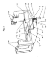
- the safety device 17, and its operation, are illustrated in particular by the Figures 2 to 5 , which is now referred to.
- the safety device 17 is here carried by the rear portion of the frame 18 of the carriage 12, that is to say its nearest part of the top of the mast 5 of the crane.
- This safety device 17 mainly consists of a movable stop element 19 and a rocker lever 20.
- the movable stop member 19 is in the form of a cylindrical rod, slidably mounted along an axis A whose direction is contained in a longitudinal vertical plane of the arrow 6, and oriented perpendicularly to the direction of movement of the carriage 12, in other words to the longitudinal direction of the arrow 6.
- the movable stop member 19 is slidably mounted in a guide block 21 integral with the frame 18 of the carriage 12, and it also slidably traverses a guide tab 22 fixed under the frame 18 of the carriage 12.
- an annular shoulder 23 which takes place between the guide block 21 and the guide lug 22.
- a coil spring 24 is mounted around the movable stop member 19, the spring 24 being placed and compressed between the annular shoulder 23 and the guide lug 22.
- the rear portion of the frame 18 of the carriage 12 carries, close to the movable stop member 19, a short axis 25 orthogonal to the sliding direction A of this movable stop element 19, the axis 25 being more particularly oriented in the direction of travel of the carriage 12.
- the rocking lever 20 is pivotally mounted by an intermediate sleeve 26 on the axis 25.
- This rocker lever 20 has a first arm 27 which, starting from the hinge sleeve 26, forms several successive bends and passes on the distribution cable 13, more particularly on the rear distribution cable 13b.
- the rocking lever 20 also has a second arm 28, opposite to the previous one and of shorter length, which is provided to cooperate with the annular shoulder 23 of the movable stop element 19.
- the figures 2 and 3 represent the components previously described in their normal position, that is to say the position they occupy as long as the distribution cable 13, in particular here the rear distribution cable 13b, is intact and normally stretched, thus allowing the motorized control of the displacement of the carriage 12 on its raceway.
- the rocker lever 20 is then held in its position by the support of its first arm 27 on the cable 13, more particularly the rear distribution cable 13b, which is tensioned.
- the corresponding position of the second arm 28 of the rocking lever 20, which bears against the annular shoulder 23 of the movable stop element 19, is such that this movable stop element 19 is kept lowered, while the spring 24 is compressed.
Landscapes
- Engineering & Computer Science (AREA)
- Mechanical Engineering (AREA)
- Jib Cranes (AREA)
- Control And Safety Of Cranes (AREA)
Claims (8)
- Turmkran mit Katzausleger oder Gitterausleger, mit einer Sicherheitsvorrichtung (17), die einer Laufkatze (12) zugeordnet ist und die Aufgabe hat, die Laufkatze (12) bei einem fehlerbedingten Reißen des Laufseils (13) dieser Laufkatze (12) automatisch auf dem Ausleger (6) des Krans zu immobilisieren, wobei die Vorrichtung (17) auf die Laufkatze (12) montiert ein bewegliches Arretierelement (19) aufweist, das im Fall des Reißens des Seils (13) freigegeben wird und sich dann in ein Gitter des Auslegers (6) einfügt, um von einem Querelement (10; 11) dieses Gitters arretiert zu werden, dadurch gekennzeichnet, dass die Sicherheitsvorrichtung (17) in Kombination enthält:- ein bewegliches stangenförmiges Arretierelement (19), das auf der Laufkatze (12) in einer Richtung (A) im Wesentlichen orthogonal zur Längsrichtung des Auslegers (6) translationsgeführt und durch Federeinrichtungen (24) oder durch Betätigungseinrichtungen in Richtung seines Einfügens in das Gitter des Auslegers (6) beaufschlagt wird; und- Erfassungs- und Auslöseeinrichtungen (20), die von der Laufkatze (12) getragen werden und das Reißen des Seils (13) erfassen können, wobei diese Einrichtungen (20) konzipiert sind, um normalerweise das bewegliche Arretierelement (19) in der bezüglich des Gitters des Auslegers (6) zurückgeschobenen Stellung zurückzuhalten, und um dieses bewegliche Arretierelement (19) freizugeben und im Fall des Reißens des Seils (13) seine Einfügung in das Gitter (10; 11) des Auslegers (6) unter der Wirkung der Federeinrichtungen (24) oder der Betätigungseinrichtungen zu erlauben.
- Turmkran nach Anspruch 1, dadurch gekennzeichnet, dass das bewegliche Arretierelement (19) auf der Laufkatze (12) in einer Richtung (A) gleitend montiert ist, die in einer senkrechten Längsebene des Auslegers (6) enthalten ist, wobei das bewegliche Arretierelement (19) somit vorgesehen ist, um sich im Fall des Reißens des Seils (13) in das waagrechte Gitter (10) des Auslegers (6) einzufügen.
- Turmkran nach Anspruch 1, dadurch gekennzeichnet, dass das bewegliche Arretierelement (19) auf der Laufkatze (12) in einer Richtung quer zu einer senkrechten Längsebene des Auslegers (6) gleitend montiert ist, wobei das bewegliche Arretierelement (19) somit vorgesehen ist, um sich im Fall des Reißens des Seils (13) in ein seitliches Gitter (11) des Auslegers (6) einzufügen.
- Turmkran nach einem der Ansprüche 1 bis 3, dadurch gekennzeichnet, dass die Einrichtungen zum Erfassen des Reißens des Seils und zum Auslösen mechanisch in Form eines Kipphebels (20) hergestellt werden, der auf die Laufkatze (12) um eine Achse (25) schwenkbar montiert ist, die zur Richtung des Gleitens (A) des beweglichen Arretierelements (19) orthogonal ist, wobei der Kipphebel (20) einen ersten Arm (27), der mit dem Seil (13) zusammenwirkt, und einen zweiten Arm (28) besitzt, der außer im Fall des Reißens des Seils (13) mit einer Rückhalteschulter (23) zusammenwirkt, die auf dem beweglichen Arretierelement (19) ausgebildet ist, indem er die Federeinrichtungen (24) im gespannten Zustand hält.
- Turmkran nach Anspruch 4, dadurch gekennzeichnet, dass die Sicherheitsvorrichtung (17) Federeinrichtungen enthält, die aus einer Spiralfeder (24) bestehen, die um das wie eine zylindrische Stange hergestellte bewegliche Arretierelement (19) herum montiert ist und normalerweise zwischen der erwähnten Schulter (23) des beweglichen Arretierelements (19) und einem Führungsorgan (22) dieses beweglichen Arretierelements (19) komprimiert gehalten wird.
- Turmkran nach einem der Ansprüche 1 bis 3, dadurch gekennzeichnet, dass die Einrichtungen zum Erfassen des Reißens des Seils und zum Auslösen elektrisch oder hydraulisch realisiert werden, mit einem Erfassungshebel, der mittels eines elektrischen Schalters oder seines hydraulischen Äquivalents wirkt.
- Turmkran nach Anspruch 6, dadurch gekennzeichnet, dass er Betätigungseinrichtungen des beweglichen Arretierelements (19) enthält, die aus einem pneumatischen oder hydraulischen oder elektrischen Druckzylinder bestehen.
- Turmkran nach einem der Ansprüche 1 bis 7, dadurch gekennzeichnet, dass dieser Kran ein Turmkran mit Wipp-Katzausleger (6) ist.
Applications Claiming Priority (1)
| Application Number | Priority Date | Filing Date | Title |
|---|---|---|---|
| FR0503482A FR2884240B1 (fr) | 2005-04-07 | 2005-04-07 | Dispositif de securite pour chariot de grue |
Publications (2)
| Publication Number | Publication Date |
|---|---|
| EP1710197A1 EP1710197A1 (de) | 2006-10-11 |
| EP1710197B1 true EP1710197B1 (de) | 2010-06-02 |
Family
ID=35229874
Family Applications (1)
| Application Number | Title | Priority Date | Filing Date |
|---|---|---|---|
| EP20060003352 Expired - Lifetime EP1710197B1 (de) | 2005-04-07 | 2006-02-20 | Sicherheitsvorrichtung für Laufkatze eines Krans |
Country Status (6)
| Country | Link |
|---|---|
| EP (1) | EP1710197B1 (de) |
| DE (1) | DE602006014613D1 (de) |
| ES (1) | ES2346991T3 (de) |
| FR (1) | FR2884240B1 (de) |
| PT (1) | PT1710197E (de) |
| RU (1) | RU2394748C2 (de) |
Cited By (3)
| Publication number | Priority date | Publication date | Assignee | Title |
|---|---|---|---|---|
| CN101794146A (zh) * | 2010-02-11 | 2010-08-04 | 浙江建机科技研发有限公司 | 用于塔式起重机的管理系统 |
| CN102022018B (zh) * | 2009-09-11 | 2012-06-27 | 深圳市海生机房技术有限公司 | 升降塔以及移动式基站 |
| US8967117B2 (en) | 2012-09-05 | 2015-03-03 | Honeywell International Inc. | Throttle control assembly with integrated safety switch |
Families Citing this family (7)
| Publication number | Priority date | Publication date | Assignee | Title |
|---|---|---|---|---|
| CN101823495B (zh) * | 2010-03-15 | 2013-03-20 | 中国原子能科学研究院 | 一种燃料倾斜运输轨道车的防坠落的非能动装置 |
| DE202010005201U1 (de) * | 2010-04-14 | 2010-06-17 | Wilbert Turmkrane Gmbh | Sicherheitssystem für eine Laufkatze eines Kranes |
| DE202010008078U1 (de) * | 2010-07-14 | 2010-10-07 | Wilbert Turmkrane Gmbh | Sicherheitssystem für eine Laufkatze eines Krans |
| WO2014075276A1 (zh) * | 2012-11-15 | 2014-05-22 | 中联重科股份有限公司 | 托绳装置、塔机起重臂及其吊绳防坠方法、塔机 |
| CN103482509B (zh) * | 2013-08-13 | 2016-08-10 | 河南卫华重型机械股份有限公司 | 钢丝绳固定装置 |
| CN107140541A (zh) * | 2017-03-20 | 2017-09-08 | 无锡职业技术学院 | 一种检测式起吊机 |
| CN117963722B (zh) * | 2024-04-01 | 2024-05-31 | 河南新创业起重机械有限公司 | 一种汽车维修吊装装置 |
Family Cites Families (8)
| Publication number | Priority date | Publication date | Assignee | Title |
|---|---|---|---|---|
| DE1171132B (de) * | 1961-05-02 | 1964-05-27 | Reich Fa Wilhelm | Turmdrehkran mit einziehbarem Ausleger und an diesem gefuehrter Laufkatze |
| GB972436A (en) * | 1962-07-31 | 1964-10-14 | Stothert & Pitt Ltd | A safety device for cranes |
| GB1008220A (en) * | 1963-01-31 | 1965-10-27 | Scharf Gmbh Heinrich | Braking device |
| GB1015255A (en) * | 1963-04-19 | 1965-12-31 | Leonard Evans | Improvements in or relating to mobile lifts or elevators |
| FR1446400A (fr) * | 1965-06-09 | 1966-07-22 | Expl Des Etablissements Boilot | Dispositif de sécurité pour chariot de grue circulant sur volée relevée |
| US3987915A (en) * | 1975-03-21 | 1976-10-26 | Conner John R | Tire storage and retrieval system and method |
| SU1312055A1 (ru) * | 1986-03-11 | 1987-05-23 | Филиал Государственного Проектного И Конструкторского Института "Союзпроммеханизация" | Устройство дл закрывани отверсти в месте прохода грузового каната через корпус подъемно-транспортной машины |
| DE19833772A1 (de) * | 1998-07-17 | 2000-01-20 | Giesen Leana | Absturzsicherung für schienengeführte Aufzüge |
-
2005
- 2005-04-07 FR FR0503482A patent/FR2884240B1/fr not_active Expired - Lifetime
-
2006
- 2006-02-20 DE DE200660014613 patent/DE602006014613D1/de active Active
- 2006-02-20 EP EP20060003352 patent/EP1710197B1/de not_active Expired - Lifetime
- 2006-02-20 ES ES06003352T patent/ES2346991T3/es not_active Expired - Lifetime
- 2006-02-20 PT PT06003352T patent/PT1710197E/pt unknown
- 2006-04-06 RU RU2006111319/11A patent/RU2394748C2/ru not_active IP Right Cessation
Cited By (3)
| Publication number | Priority date | Publication date | Assignee | Title |
|---|---|---|---|---|
| CN102022018B (zh) * | 2009-09-11 | 2012-06-27 | 深圳市海生机房技术有限公司 | 升降塔以及移动式基站 |
| CN101794146A (zh) * | 2010-02-11 | 2010-08-04 | 浙江建机科技研发有限公司 | 用于塔式起重机的管理系统 |
| US8967117B2 (en) | 2012-09-05 | 2015-03-03 | Honeywell International Inc. | Throttle control assembly with integrated safety switch |
Also Published As
| Publication number | Publication date |
|---|---|
| EP1710197A1 (de) | 2006-10-11 |
| ES2346991T3 (es) | 2010-10-22 |
| FR2884240A1 (fr) | 2006-10-13 |
| PT1710197E (pt) | 2010-09-07 |
| RU2006111319A (ru) | 2007-11-10 |
| RU2394748C2 (ru) | 2010-07-20 |
| DE602006014613D1 (de) | 2010-07-15 |
| FR2884240B1 (fr) | 2007-05-18 |
Similar Documents
| Publication | Publication Date | Title |
|---|---|---|
| EP1710197B1 (de) | Sicherheitsvorrichtung für Laufkatze eines Krans | |
| FR2922875A1 (fr) | Procede de relevage d'une fleche de grue | |
| FR2820641A1 (fr) | Antichute mobile pour support d'assurage | |
| EP3466862B1 (de) | Kran mit hochklappbarem ausleger mit verriegelungsvorrichtung des auslegers in hochgeklappter konfiguration | |
| EP1351878B1 (de) | Notbremsvorrichtung für ein kabelgezogenes oder aufgehängtes fahrzeug und fahrzeug mit einer notbremsvorrichtung | |
| EP2089302B1 (de) | Schuh zum stillstand eines rades und motorisierte stillstandanordnung | |
| FR2715965A1 (fr) | Dispositif de sécurité contre la chute, en particulier pour portes basculantes. | |
| CH620644A5 (de) | ||
| EP3924070B1 (de) | Verbinder, lösbare gabelattrappe mit einem solchen verbinder und betriebsverfahren | |
| CN212893591U (zh) | 防松绳装置、车载云梯及云梯车 | |
| FR2753387A1 (fr) | Dispositif de support mobile pour devidoir de tuyau | |
| EP2532616B1 (de) | Sicherheitssystem für eine vertikal beweglichen Plattform für einen Arbeiter | |
| FR2759684A1 (fr) | Dispositif separateur a bascule pour couloir de stockage dynamique | |
| FR2670526A1 (fr) | Dispositif d'arrachage de poteaux, en particulier de poteaux ancres dans un massif en beton. | |
| FR2808517A1 (fr) | Dispositif pour declencher le mecanisme de liberation du parachute d'une cabine d'ascenseur | |
| EP2949616B1 (de) | Teleskopmast mit integrierter sicherheitsvorrichtung für hubgerät, und hubgerät, das mit einem solchen teleskopmast ausgestattet ist | |
| FR2516022A1 (fr) | Chariot a trois roues | |
| FR2957891A1 (fr) | Bequille centrale pour moto manoeuvree electriquement s'adaptant automatiquement a l'inclinaison du sol | |
| EP1964979A1 (de) | Pfahlrammvorrichtung mit Teleskopmast und hydraulischem Hammer | |
| FR2723706A1 (fr) | Dispositif pour fendre des billes en buches | |
| EP0285751B1 (de) | Aufzugwinde | |
| FR2566379A1 (fr) | Engin de levage mobile, notamment portuaire | |
| EP1433678A1 (de) | Stützbeinvorrichtung für Anhänger und damit ausgestatteter Anhänger | |
| BE528908A (de) | ||
| FR2838098A1 (fr) | Dispositif stabilisateur escamotable pour vehicule a deux roues, notamment un motocycle |
Legal Events
| Date | Code | Title | Description |
|---|---|---|---|
| PUAI | Public reference made under article 153(3) epc to a published international application that has entered the european phase |
Free format text: ORIGINAL CODE: 0009012 |
|
| AK | Designated contracting states |
Kind code of ref document: A1 Designated state(s): AT BE BG CH CY CZ DE DK EE ES FI FR GB GR HU IE IS IT LI LT LU LV MC NL PL PT RO SE SI SK TR |
|
| AX | Request for extension of the european patent |
Extension state: AL BA HR MK YU |
|
| 17P | Request for examination filed |
Effective date: 20070117 |
|
| 17Q | First examination report despatched |
Effective date: 20070426 |
|
| AKX | Designation fees paid |
Designated state(s): DE ES IT PT |
|
| RAP1 | Party data changed (applicant data changed or rights of an application transferred) |
Owner name: MANITOWOC CRANE GROUP FRANCE |
|
| GRAP | Despatch of communication of intention to grant a patent |
Free format text: ORIGINAL CODE: EPIDOSNIGR1 |
|
| GRAS | Grant fee paid |
Free format text: ORIGINAL CODE: EPIDOSNIGR3 |
|
| GRAA | (expected) grant |
Free format text: ORIGINAL CODE: 0009210 |
|
| AK | Designated contracting states |
Kind code of ref document: B1 Designated state(s): DE ES IT PT |
|
| REF | Corresponds to: |
Ref document number: 602006014613 Country of ref document: DE Date of ref document: 20100715 Kind code of ref document: P |
|
| REG | Reference to a national code |
Ref country code: PT Ref legal event code: SC4A Free format text: AVAILABILITY OF NATIONAL TRANSLATION Effective date: 20100831 |
|
| REG | Reference to a national code |
Ref country code: ES Ref legal event code: FG2A Ref document number: 2346991 Country of ref document: ES Kind code of ref document: T3 |
|
| PLBE | No opposition filed within time limit |
Free format text: ORIGINAL CODE: 0009261 |
|
| STAA | Information on the status of an ep patent application or granted ep patent |
Free format text: STATUS: NO OPPOSITION FILED WITHIN TIME LIMIT |
|
| 26N | No opposition filed |
Effective date: 20110303 |
|
| REG | Reference to a national code |
Ref country code: DE Ref legal event code: R097 Ref document number: 602006014613 Country of ref document: DE Effective date: 20110302 |
|
| PGFP | Annual fee paid to national office [announced via postgrant information from national office to epo] |
Ref country code: PT Payment date: 20150123 Year of fee payment: 10 |
|
| PG25 | Lapsed in a contracting state [announced via postgrant information from national office to epo] |
Ref country code: PT Free format text: LAPSE BECAUSE OF NON-PAYMENT OF DUE FEES Effective date: 20160822 |
|
| PGFP | Annual fee paid to national office [announced via postgrant information from national office to epo] |
Ref country code: DE Payment date: 20240219 Year of fee payment: 19 |
|
| PGFP | Annual fee paid to national office [announced via postgrant information from national office to epo] |
Ref country code: ES Payment date: 20250328 Year of fee payment: 20 |
|
| PGFP | Annual fee paid to national office [announced via postgrant information from national office to epo] |
Ref country code: IT Payment date: 20250224 Year of fee payment: 20 |
|
| REG | Reference to a national code |
Ref country code: DE Ref legal event code: R119 Ref document number: 602006014613 Country of ref document: DE |
|
| PG25 | Lapsed in a contracting state [announced via postgrant information from national office to epo] |
Ref country code: DE Free format text: LAPSE BECAUSE OF NON-PAYMENT OF DUE FEES Effective date: 20250902 |