EP0285751B1 - Aufzugwinde - Google Patents
Aufzugwinde Download PDFInfo
- Publication number
- EP0285751B1 EP0285751B1 EP88100910A EP88100910A EP0285751B1 EP 0285751 B1 EP0285751 B1 EP 0285751B1 EP 88100910 A EP88100910 A EP 88100910A EP 88100910 A EP88100910 A EP 88100910A EP 0285751 B1 EP0285751 B1 EP 0285751B1
- Authority
- EP
- European Patent Office
- Prior art keywords
- winch
- support
- stop
- elastic
- bar
- Prior art date
- Legal status (The legal status is an assumption and is not a legal conclusion. Google has not performed a legal analysis and makes no representation as to the accuracy of the status listed.)
- Expired - Lifetime
Links
Images

Classifications
-
- B—PERFORMING OPERATIONS; TRANSPORTING
- B66—HOISTING; LIFTING; HAULING
- B66D—CAPSTANS; WINCHES; TACKLES, e.g. PULLEY BLOCKS; HOISTS
- B66D1/00—Rope, cable, or chain winding mechanisms; Capstans
- B66D1/54—Safety gear
- B66D1/56—Adaptations of limit switches
-
- B—PERFORMING OPERATIONS; TRANSPORTING
- B66—HOISTING; LIFTING; HAULING
- B66B—ELEVATORS; ESCALATORS OR MOVING WALKWAYS
- B66B5/00—Applications of checking, fault-correcting, or safety devices in elevators
- B66B5/02—Applications of checking, fault-correcting, or safety devices in elevators responsive to abnormal operating conditions
- B66B5/08—Applications of checking, fault-correcting, or safety devices in elevators responsive to abnormal operating conditions for preventing overwinding
- B66B5/10—Applications of checking, fault-correcting, or safety devices in elevators responsive to abnormal operating conditions for preventing overwinding electrical
-
- B—PERFORMING OPERATIONS; TRANSPORTING
- B66—HOISTING; LIFTING; HAULING
- B66B—ELEVATORS; ESCALATORS OR MOVING WALKWAYS
- B66B9/00—Kinds or types of lifts in, or associated with, buildings or other structures
- B66B9/16—Mobile or transportable lifts specially adapted to be shifted from one part of a building or other structure to another part or to another building or structure
Definitions
- the subject of the present invention is a mobile hoist winch on a support and comprising an elastic stop placed between the support and the winch and a switch actuated by raising the winch on its support after the traction force has overcome the resistance. of the elastic stop when the load abuts against a limit stop or exceeds a certain value or when the load is accidentally blocked.
- the winch In known mobile site hoists using rails on which the load is moved, the winch is rigidly fixed to the rails and the limit switch, generally compulsory, is located at the end of the rail reached by load.
- This construction has the major drawback of requiring a cable running along the rails between the winch and the limit switch. This cable, as well as the limit switch, is exposed to knocks and bad weather, so that one or the other can deteriorate, causing the limit switch not to function. , which can be the cause of a serious accident.
- the electrical cable In addition, each time the installation is mounted, shortened or extended, the electrical cable must be installed again.
- a winch which is fixed on its support on the one hand by an articulation axis parallel to the axis of the winch and on the other hand by an elastic support element partially compensating for the weight of the winch, the resulting force maintaining, at rest, a closed contact.
- the winch is raised and stopped by opening the contact. Due to the design of its support, this winch is intended to be fixed against a wall.
- the present invention aims to achieve, on the same principle as the known winch, a winch capable of being removably and instantaneously mounted on rungs of rails such as they are encountered in construction sites for the elevation of construction materials .
- the invention also aims to overcome the drawbacks of known mobile installations.
- the winch as defined by claim 1 achieves these goals.
- the limit switch is integrated into the winch itself.
- the same is true of the elastic stops which determine the force with which the winch must be raised in order for the limit switch and the safety switch to be actuated.
- the inventive idea lies in particular in the fact of using the bars of the rails to fix the winch with sufficient clearance to allow the actuation of the limit switch by moving the winch.
- the winch is advantageously provided with rapid and automatic hooking means making it possible to fix the winch to the bars of the rails by placing it by its lower part on a bar and making it simply tilt on this bar to hang it on the upper bar.
- the invention is not limited to an electric winch, but also extends to a winch driven by an internal combustion engine.
- the winch comprises a winch drum 1 on which a cable is wound 2.
- the drum 1 is driven by an electric motor 3 by means of a speed reducing gear contained in a box 4 also containing the motor switching means 3.
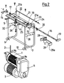
- the assembly formed by these elements is fixed by means of screws with two horizontal bars 5 and 6 secured to a tubular frame 7, the whole being covered by a cover 8 shown only in FIG. 1.
- This frame 7 is provided , at its lower part, with two supports 9 and 10 in the form of an inverted gutter whose internal diameter corresponds to the diameter of the bars such as 11, 37 and 38 connecting two rails 12 and 13.
- the frame 7 is provided two hooks 14 and 15 integral in rotation with a bar 16 rotatably mounted in two pairs of supports 17 and 18 and provided with a lever 19 whose role will be described later.
- the hooks 14 and 15 are held in the position shown in FIG. 2 by a hunting horn spring 20 mounted around the bar 16 and one end of which rests on the hook 15.
- the hooks 14 and 15 are locked in the position represented by a locking bar 21 slidably mounted in two ends of the tube 22 and 23.
- the locking is provided by the end 21 of the locking bar 21 which engages under the lever 19.
- the bar 21 is held in this position by a spring 24. To unlock the lever 19, it suffices to pull the bar 21 by its bent end 21 b.
- a transverse angle 25 the frame 7 is further fixed a limit switch 26.
- the angle 25 further carries the bars 5 and 6 supporting the winch.
- two elastic stops are fixed, one of which, 27 is visible in FIG. 1, while the other, 28 has been shown in FIG. 2.
- Each of these stops is fixed on a lateral arm 29, respectively 31, itself fixed by means of screws on a side plate 30, respectively 32, of the frame.
- the arm 29 has a bent end 31a. The two bent ends 29a and 31a serve to guide and position the winch on its support, that is to say on the rails 12 and 13.
- One of the elastic stops is shown in section in FIG. 3. It comprises a rod 33 passing through a tubular cage 34 containing a pack of springs 35 on which a flange 36 of the rod 33 rests.
- the pack of springs is chosen and calibrated according to the weight of the winch and the maximum load that can be lifted.
- the lever 19 is unlocked by pulling on the bar. 21 and by hooking the bent end 21 b of this bar against the side wall of the cover 8.
- the winch is then placed on a bar 37 by engaging its supports 9 and 10 on this bar.
- the winch is then pivoted around the bar 37 in the direction of the arrow F so that the hooks 14 and 15 are lifted by the bar 38 and come to hang on this bar 38.
- the elastic stops 27 and 28 are placed just below the bar 38 at a very short distance from this bar or even in contact with this bar.
- the switch 26 is also placed under the bar 38.
- the locking rod 21 is then released and locks the lever 19, that is to say the hooks 14 and 15, as shown in FIG. 1, to prevent the winch to accidentally detach from its support.
- the winch As soon as the traction on the winch cable exceeds the weight of this winch, the winch is pulled upwards and its elastic stops 27 and 28 come to bear against the bar 38. As soon as the traction on the winch cable reaches a value limit determined by the spring packets 35, for example when the load driven by the winch reaches the end of travel, the compression of the spring packets is such that the limit switch 26 is actuated by the bar 38 and the winch motor is stopped. As soon as the winch motor is switched in the opposite direction, the winch is returned to its initial position by the elastic stops 27 and 28.
- a small movement of the winch is sufficient to actuate the limit switch 26, this small movement in no way creating a risk of accidental detachment of the winch.
- the elastic stops could be adjustable and even graduated.
- mounting the winch on its support it could be achieved in any other way, for example by means of flanges.
- the switch and the elastic stops could cooperate with different bars or with auxiliary stops fixed on the rails.
Landscapes
- Engineering & Computer Science (AREA)
- Structural Engineering (AREA)
- Mechanical Engineering (AREA)
- Civil Engineering (AREA)
- Transportation (AREA)
- Automation & Control Theory (AREA)
- Types And Forms Of Lifts (AREA)
- Jib Cranes (AREA)
- Lift-Guide Devices, And Elevator Ropes And Cables (AREA)
Claims (3)
Priority Applications (1)
| Application Number | Priority Date | Filing Date | Title |
|---|---|---|---|
| AT88100910T ATE51387T1 (de) | 1987-02-09 | 1988-01-22 | Aufzugwinde. |
Applications Claiming Priority (2)
| Application Number | Priority Date | Filing Date | Title |
|---|---|---|---|
| CH467/87 | 1987-02-09 | ||
| CH46787 | 1987-02-09 |
Publications (2)
| Publication Number | Publication Date |
|---|---|
| EP0285751A1 EP0285751A1 (de) | 1988-10-12 |
| EP0285751B1 true EP0285751B1 (de) | 1990-03-28 |
Family
ID=4187679
Family Applications (1)
| Application Number | Title | Priority Date | Filing Date |
|---|---|---|---|
| EP88100910A Expired - Lifetime EP0285751B1 (de) | 1987-02-09 | 1988-01-22 | Aufzugwinde |
Country Status (3)
| Country | Link |
|---|---|
| EP (1) | EP0285751B1 (de) |
| AT (1) | ATE51387T1 (de) |
| DE (1) | DE3860060D1 (de) |
Families Citing this family (1)
| Publication number | Priority date | Publication date | Assignee | Title |
|---|---|---|---|---|
| DE102012004144B4 (de) * | 2012-02-29 | 2016-02-04 | Gerüstbau Witte GmbH | Vorrichtung zum Einbau von mindestens einem Seil, insbesondere im Bereich des Gerüstbaus, und Verfahren für den Einbau von Seilen |
Family Cites Families (4)
| Publication number | Priority date | Publication date | Assignee | Title |
|---|---|---|---|---|
| FR1411700A (fr) * | 1964-03-24 | 1965-09-24 | Comp Generale Electricite | Dispositif d'utilisation d'un palan ou d'un treuil |
| FR2398689A1 (fr) * | 1977-07-27 | 1979-02-23 | Roodt Guy | Dispositif mecanique de securite pour treuils |
| FR2422585A1 (fr) * | 1978-04-14 | 1979-11-09 | Roodt Guy | Dispositif mecanique de securite de fin de course pour treuil |
| GB2116943B (en) * | 1982-03-25 | 1987-01-28 | Devitec Ltd | Hoists and hoisting systems |
-
1988
- 1988-01-22 EP EP88100910A patent/EP0285751B1/de not_active Expired - Lifetime
- 1988-01-22 DE DE8888100910T patent/DE3860060D1/de not_active Expired - Fee Related
- 1988-01-22 AT AT88100910T patent/ATE51387T1/de active
Also Published As
| Publication number | Publication date |
|---|---|
| DE3860060D1 (de) | 1990-05-03 |
| ATE51387T1 (de) | 1990-04-15 |
| EP0285751A1 (de) | 1988-10-12 |
Similar Documents
| Publication | Publication Date | Title |
|---|---|---|
| EP0864019B1 (de) | Vorrichtung einer beweglichen abdeckung insbesondere für schwimmbecken | |
| FR2479783A1 (fr) | Dispositif pour le basculement de bacs a dechets dans une benne de collecte | |
| EP0635450A1 (de) | Verfahren und Vorrichtung zum Montieren der Ausleger von Turmkränen | |
| FR2581004A1 (fr) | Dispositif de manoeuvre de conteneur | |
| CH634798A5 (fr) | Dispositif automatique d'intervention destine a arreter le mouvement d'inclinaison d'une nacelle suspendue a deux ou plusieurs treuils. | |
| FR2758150A1 (fr) | Dispositif de securite applique aux appareils de levage de materiaux au niveau des plafonds | |
| EP0285751B1 (de) | Aufzugwinde | |
| WO2012123672A2 (fr) | Ensemble à cadre de support et grille de sécurité antichute réversible pouvant être montée articulée à l'un ou l'autre des deux côtés opposés du cadre | |
| FR2638007A2 (fr) | Dispositif pour l'adaptation d'un support d'affiches a un mat tel qu'un corps de reverbere | |
| EP0233090B1 (de) | Altglasbehälter | |
| EP0005099B1 (de) | Mechanische Vorrichtung zum Endabschalten von Winden | |
| EP0480540A2 (de) | Flexible aufrollbare Tür | |
| FR2684341A1 (fr) | Dispositif pour hisser ou retirer une echelle ou analogue sur ou a partir d'une galerie de toit d'un vehicule. | |
| CH682914A5 (fr) | Dispositif de levage et de déplacement de charges. | |
| CH367957A (fr) | Grue à mât relevable | |
| WO2021079219A1 (fr) | Grue à flèche télescopique et procédé de manutention d'une charge à l'aide d'une telle grue | |
| EP0330642B1 (de) | Leiterfahrkorb | |
| FR2726029A1 (fr) | Echelle, notamment pour cuvette d'acenseur, kit ou ensemble pret a monter de securite et procede pour securiser une telle echelle | |
| EP0258919B1 (de) | Vorrichtung, die es ermöglicht, in einem Gebäude Zugang zu einem mit einer Luke verschlossenen Ausgang zu verleihen | |
| EP3121135A1 (de) | Hebe- und transportplatte für halbunterirdischer behälter | |
| FR2584300A1 (fr) | But de basket-ball relevable avec panneau reglable en hauteur | |
| FR2534000A1 (fr) | Barriere mobile de securite, en particulier pour le dechargement en fosse de vehicules | |
| FR2526777A1 (fr) | Dispositif d'escamotage pour appareil de levage du type a parallelogramme deformable | |
| FR2726028A1 (fr) | Echelle de securite mobile, notamment pour cuvette d'ascenseur | |
| BE495769A (de) |
Legal Events
| Date | Code | Title | Description |
|---|---|---|---|
| PUAI | Public reference made under article 153(3) epc to a published international application that has entered the european phase |
Free format text: ORIGINAL CODE: 0009012 |
|
| AK | Designated contracting states |
Kind code of ref document: A1 Designated state(s): AT BE CH DE FR IT LI LU NL |
|
| 17P | Request for examination filed |
Effective date: 19881024 |
|
| 17Q | First examination report despatched |
Effective date: 19890615 |
|
| GRAA | (expected) grant |
Free format text: ORIGINAL CODE: 0009210 |
|
| AK | Designated contracting states |
Kind code of ref document: B1 Designated state(s): AT BE CH DE FR IT LI LU NL |
|
| REF | Corresponds to: |
Ref document number: 51387 Country of ref document: AT Date of ref document: 19900415 Kind code of ref document: T |
|
| ITF | It: translation for a ep patent filed | ||
| REF | Corresponds to: |
Ref document number: 3860060 Country of ref document: DE Date of ref document: 19900503 |
|
| PLBE | No opposition filed within time limit |
Free format text: ORIGINAL CODE: 0009261 |
|
| STAA | Information on the status of an ep patent application or granted ep patent |
Free format text: STATUS: NO OPPOSITION FILED WITHIN TIME LIMIT |
|
| 26N | No opposition filed | ||
| ITTA | It: last paid annual fee | ||
| PGFP | Annual fee paid to national office [announced via postgrant information from national office to epo] |
Ref country code: CH Payment date: 19930125 Year of fee payment: 6 |
|
| PGFP | Annual fee paid to national office [announced via postgrant information from national office to epo] |
Ref country code: FR Payment date: 19930127 Year of fee payment: 6 |
|
| PGFP | Annual fee paid to national office [announced via postgrant information from national office to epo] |
Ref country code: DE Payment date: 19930128 Year of fee payment: 6 Ref country code: AT Payment date: 19930128 Year of fee payment: 6 |
|
| PGFP | Annual fee paid to national office [announced via postgrant information from national office to epo] |
Ref country code: NL Payment date: 19930131 Year of fee payment: 6 |
|
| PGFP | Annual fee paid to national office [announced via postgrant information from national office to epo] |
Ref country code: BE Payment date: 19930226 Year of fee payment: 6 |
|
| PGFP | Annual fee paid to national office [announced via postgrant information from national office to epo] |
Ref country code: LU Payment date: 19930316 Year of fee payment: 6 |
|
| EPTA | Lu: last paid annual fee | ||
| PG25 | Lapsed in a contracting state [announced via postgrant information from national office to epo] |
Ref country code: LU Free format text: LAPSE BECAUSE OF NON-PAYMENT OF DUE FEES Effective date: 19940122 Ref country code: AT Effective date: 19940122 |
|
| PG25 | Lapsed in a contracting state [announced via postgrant information from national office to epo] |
Ref country code: LI Effective date: 19940131 Ref country code: CH Effective date: 19940131 Ref country code: BE Effective date: 19940131 |
|
| BERE | Be: lapsed |
Owner name: S.A. RIEDER Effective date: 19940131 |
|
| PG25 | Lapsed in a contracting state [announced via postgrant information from national office to epo] |
Ref country code: NL Effective date: 19940801 |
|
| NLV4 | Nl: lapsed or anulled due to non-payment of the annual fee | ||
| PG25 | Lapsed in a contracting state [announced via postgrant information from national office to epo] |
Ref country code: FR Effective date: 19940930 |
|
| REG | Reference to a national code |
Ref country code: CH Ref legal event code: PL |
|
| PG25 | Lapsed in a contracting state [announced via postgrant information from national office to epo] |
Ref country code: DE Effective date: 19941001 |
|
| REG | Reference to a national code |
Ref country code: FR Ref legal event code: ST |
|
| PG25 | Lapsed in a contracting state [announced via postgrant information from national office to epo] |
Ref country code: IT Free format text: LAPSE BECAUSE OF NON-PAYMENT OF DUE FEES;WARNING: LAPSES OF ITALIAN PATENTS WITH EFFECTIVE DATE BEFORE 2007 MAY HAVE OCCURRED AT ANY TIME BEFORE 2007. THE CORRECT EFFECTIVE DATE MAY BE DIFFERENT FROM THE ONE RECORDED. Effective date: 20050122 |