EP1710197B1 - Safety device for crane trolley - Google Patents
Safety device for crane trolley Download PDFInfo
- Publication number
- EP1710197B1 EP1710197B1 EP20060003352 EP06003352A EP1710197B1 EP 1710197 B1 EP1710197 B1 EP 1710197B1 EP 20060003352 EP20060003352 EP 20060003352 EP 06003352 A EP06003352 A EP 06003352A EP 1710197 B1 EP1710197 B1 EP 1710197B1
- Authority
- EP
- European Patent Office
- Prior art keywords
- cable
- jib
- arresting element
- lattice
- breakage
- Prior art date
- Legal status (The legal status is an assumption and is not a legal conclusion. Google has not performed a legal analysis and makes no representation as to the accuracy of the status listed.)
- Active
Links
- 238000001514 detection method Methods 0.000 claims description 7
- 230000003100 immobilizing effect Effects 0.000 claims description 2
- 230000000694 effects Effects 0.000 description 6
- 238000005096 rolling process Methods 0.000 description 4
- 238000006073 displacement reaction Methods 0.000 description 3
- 101100536354 Drosophila melanogaster tant gene Proteins 0.000 description 1
- 229910000831 Steel Inorganic materials 0.000 description 1
- 240000008042 Zea mays Species 0.000 description 1
- 238000005452 bending Methods 0.000 description 1
- 230000003111 delayed effect Effects 0.000 description 1
- 230000001687 destabilization Effects 0.000 description 1
- 230000005484 gravity Effects 0.000 description 1
- 239000000463 material Substances 0.000 description 1
- 230000035939 shock Effects 0.000 description 1
- 239000010959 steel Substances 0.000 description 1
Images


Classifications
-
- B—PERFORMING OPERATIONS; TRANSPORTING
- B66—HOISTING; LIFTING; HAULING
- B66C—CRANES; LOAD-ENGAGING ELEMENTS OR DEVICES FOR CRANES, CAPSTANS, WINCHES, OR TACKLES
- B66C9/00—Travelling gear incorporated in or fitted to trolleys or cranes
- B66C9/18—Travelling gear incorporated in or fitted to trolleys or cranes with means for locking trolleys or cranes to runways or tracks to prevent inadvertent movements
Definitions
- the present invention relates generally to the field of tower cranes with a distributing boom, along which is movable a carriage driven by a cable. More particularly, this invention relates to a safety device for the carriage of such a crane, that is to say a device whose function is to automatically immobilize the carriage on the boom of the crane, in case accidental breaking of the cable of displacement of this truck.
- the boom In a tower crane, in use, the boom is never perfectly horizontal. On the one hand, even for use in a theoretically horizontal position, the bending of the mast and the boom itself place this boom in a slightly inclined position. In particular, if the raised load is located below the front half of a theoretically horizontal boom, the front portion of the boom tilts down. On the other hand, for some tower cranes, there are possibilities of operation with more or less raised boom, so inclined to the horizontal.
- the patent FR 1446400 discloses a crane cart safety device which is based on a somewhat different principle.
- a lever is pivotally mounted about a horizontal axis on the carriage and it carries brake shoes provided to cooperate with the longitudinal elements of the boom, in case of breakage of the carriage moving cable. Braking of the carriage is thus effected by a frictional contact between parts usually painted steel, so with a low coefficient of friction, hence a braking efficiency itself low.
- the brake lever when the brake lever is released to stop the truck, the lever will bounce off the boom members and oscillate around its pivot axis, further reducing the speed and efficiency of braking.
- such a system at best achieves only a more or less strong braking of the carriage by friction against elements of the crane boom, and not a certain stop by abutment contact with an obstacle element in pursuit of moving the carriage.
- the patent GB 1015255 discloses a movable finger device, engageable in the teeth of a rack in case of breakage of the cable, the movable finger having a terminal ring through which the cable.
- Such a device ensures only a braking and a "mono-directional" stop, that is to say that it intervenes only in the direction of the down the platform or nacelle, while for a crane boom, the truck must be braked and stopped in a "bi-directional" manner, according to the direction of inclination of the boom portion on which the carriage is located.
- the addition of a rack is acceptable in the case of a compact hoist, but would be a complex and very expensive solution in the case of a crane boom, whose length can reach 40 to 80 meters .
- the present invention aims to eliminate these disadvantages, and it is therefore intended to provide a safety device for a crane truck, which has a very high reliability, and which is particularly effective, this device providing a braking and a stop "bi- directional "and also working very satisfactorily if the boom of the crane is strongly raised, knowing that the more the boom is inclined, the greater the risk in case of rupture of the cable is important.
- the invention provides a safety device for a crane truck in which the functions of detecting the breaking of the cable and of stopping the carriage as a result of the breakage of the cable are clearly separated.
- the safety device works very well even if the boom is raised strongly, the action of the spring means is not influenced by the inclination of the boom, and the design of this device also avoids any unexpected operation if the cable is only relaxed, without being broken.
- the solution of the invention remains simple and economical, because it uses the existing mesh of the boom of the crane, regardless of the length of the boom, no additional element such as a rack being necessary.
- the movable stop member is slidably mounted on the carriage in a direction contained in a longitudinal vertical plane of the boom, and is thus intended to engage in case of breakage. cable, in the horizontal lattice of the arrow.
- the movable stop element is slidably mounted on the carriage in a direction transverse to a longitudinal vertical plane of the boom, and is thus designed to engage, in the event of breakage of the cable, in a trellis side of the arrow.
- the cable rupture detection and triggering means are mechanically feasible, in the form of a rocker lever pivotally mounted on the carriage about an axis orthogonal to the direction of sliding of the movable stop element, the tilting lever having a first arm which cooperates with the cable, and a second arm which, except in the event of breakage of the cable, cooperates with a retaining shoulder formed on the movable stop element, maintaining the spring means in a state under stress.
- the spring means are advantageously constituted by a helical spring, mounted around the movable stop member formed as a cylindrical rod, and normally kept compressed between the aforementioned shoulder of the mobile stop member and a guide member of the movable stop member.
- the means for detecting cable rupture and tripping can be made electrically or hydraulically, that is to say in the form of a detection lever similar to that previously mentioned, but acting by means of intermediate of an electrical switch, or its hydraulic equivalent, to release the mobile stop member, and allow its engagement in the structure of the arrow.
- the spring means replaceable by actuating means of the movable stopping element, constituted by a pneumatic cylinder or hydraulic or electric.
- the figure 1 represents a liftable luffing tower crane to which the present invention is applied.
- this crane comprises mainly: a fixed base frame 2, bearing on the ground 3; a rotating frame 4 rotatably mounted on the fixed base frame 2; a folding mast 5, articulated by its lower part on the rotating frame 4; a dispensing arrow 6, which in the example shown is an arrow 6 hinged about a horizontal axis on the top of the mast 5 and thus made liftable; a device 7 for retaining the arrow 6, in the horizontal position or in the desired inclination (the figure 1 representing the arrow 6 in the raised position).
- the arrow 6 which is here triangular section comprises two lower ribs 8, and a single upper chord 9.
- the two lower chords 8 are connected to each other by transverse bars 10 or "cross”, regularly spaced so as to form a "horizontal" lattice (with reference to the arrow itself in horizontal position).
- Each of the two lower ribs 8 is connected to the upper chord 9 by diagonal slits 11, so as to also form two lateral lattices.
- the two lower ribs 8 form a raceway, for an arrow carriage 12 thus made movable along the entire length of the arrow 6.
- the carriage 12 is moved along the arrow 6 by means of a cable 13 called “cable distribution "motorized by means of a winch here not detailed, the distribution cable 13 decomposing into a front distribution cable 13a and a rear distribution cable 13b.
- the crane further comprises a hoisting rope 14, which forms at least two vertical strands under the carriage 12, and on which is suspended a lifting block 15, provided with a hook 16 to which a load (not shown) to be raised can be suspended. .
- the boom carriage 12 is equipped with a safety device, generally designated by the reference 17, which serves to automatically immobilize the carriage 12 in case of accidental breakage of the distribution cable 13.
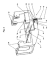
- the safety device 17, and its operation, are illustrated in particular by the Figures 2 to 5 , which is now referred to.
- the safety device 17 is here carried by the rear portion of the frame 18 of the carriage 12, that is to say its nearest part of the top of the mast 5 of the crane.
- This safety device 17 mainly consists of a movable stop element 19 and a rocker lever 20.
- the movable stop member 19 is in the form of a cylindrical rod, slidably mounted along an axis A whose direction is contained in a longitudinal vertical plane of the arrow 6, and oriented perpendicularly to the direction of movement of the carriage 12, in other words to the longitudinal direction of the arrow 6.
- the movable stop member 19 is slidably mounted in a guide block 21 integral with the frame 18 of the carriage 12, and it also slidably traverses a guide tab 22 fixed under the frame 18 of the carriage 12.
- an annular shoulder 23 which takes place between the guide block 21 and the guide lug 22.
- a coil spring 24 is mounted around the movable stop member 19, the spring 24 being placed and compressed between the annular shoulder 23 and the guide lug 22.
- the rear portion of the frame 18 of the carriage 12 carries, close to the movable stop member 19, a short axis 25 orthogonal to the sliding direction A of this movable stop element 19, the axis 25 being more particularly oriented in the direction of travel of the carriage 12.
- the rocking lever 20 is pivotally mounted by an intermediate sleeve 26 on the axis 25.
- This rocker lever 20 has a first arm 27 which, starting from the hinge sleeve 26, forms several successive bends and passes on the distribution cable 13, more particularly on the rear distribution cable 13b.
- the rocking lever 20 also has a second arm 28, opposite to the previous one and of shorter length, which is provided to cooperate with the annular shoulder 23 of the movable stop element 19.
- the figures 2 and 3 represent the components previously described in their normal position, that is to say the position they occupy as long as the distribution cable 13, in particular here the rear distribution cable 13b, is intact and normally stretched, thus allowing the motorized control of the displacement of the carriage 12 on its raceway.
- the rocker lever 20 is then held in its position by the support of its first arm 27 on the cable 13, more particularly the rear distribution cable 13b, which is tensioned.
- the corresponding position of the second arm 28 of the rocking lever 20, which bears against the annular shoulder 23 of the movable stop element 19, is such that this movable stop element 19 is kept lowered, while the spring 24 is compressed.
Description
La présente invention concerne, d'une façon générale, le domaine des grues à tour à flèche distributrice, le long de laquelle est déplaçable un chariot entraîné par un câble. Plus particulièrement, cette invention s'intéresse à un dispositif de sécurité pour le chariot d'une telle grue, c'est-à-dire un dispositif qui a pour fonction d'immobiliser automatiquement le chariot sur la flèche de la grue, en cas de rupture accidentelle du câble de déplacement de ce chariot.The present invention relates generally to the field of tower cranes with a distributing boom, along which is movable a carriage driven by a cable. More particularly, this invention relates to a safety device for the carriage of such a crane, that is to say a device whose function is to automatically immobilize the carriage on the boom of the crane, in case accidental breaking of the cable of displacement of this truck.
Dans une grue à tour, en cours d'utilisation, la flèche n'est jamais parfaitement horizontale. D'une part, même pour une utilisation en position théroriquement horizontale, la flexion du mât et de la flèche elle-même placent cette flèche dans une position légèrement inclinée. En particulier, si la charge levée est située sous la moitié avant d'une flèche théoriquement horizontale, la partie avant de la flèche s'incline vers le bas. D'autre part, pour certaines grues à tour, il existe des possibilités de fonctionnement avec flèche plus ou moins relevée, donc inclinée sur l'horizontale.In a tower crane, in use, the boom is never perfectly horizontal. On the one hand, even for use in a theoretically horizontal position, the bending of the mast and the boom itself place this boom in a slightly inclined position. In particular, if the raised load is located below the front half of a theoretically horizontal boom, the front portion of the boom tilts down. On the other hand, for some tower cranes, there are possibilities of operation with more or less raised boom, so inclined to the horizontal.
On comprend qu'en cas de rupture accidentelle du câble de déplacement du chariot, celui-ci va immédiatement, sous l'effet de son propre poids et de celui de la charge éventuellement levée à cet instant, décrire un mouvement de roulement accéléré le long de son chemin de roulement sur la flèche. Un tel mouvement peut conduire â des situations extrêmement dangereuses (collisions, chocs, déstabilisation de grue, chute de la charge levée...), s'il n'est pas immédiatement freiné et arrêté. Pour traiter ce problème, il a déjà été proposé des systèmes qui, en cas de rupture du câble de déplacement du chariot, interviennent automatiquement pour freiner et/ou pour arrêter le chariot. Des réalisations connues de tels systèmes sont, entre autres, décrites dans les brevets
Les systèmes existants, tels que celui du premier document précité
Un tel dispositif conserve des inconvénients. En particulier, lorsque le basculeur est libéré et entre en action, il existe un risque important pour qu'il rebondisse d'abord sur le treillis horizontal de la flèche, ceci étant dû au grand nombre de barres qui composent le treillis, et à la longueur du basculeur. Or si le chariot ne s'arrête pas immédiatement, son mouvement le long de la flèche sera accéléré, et le basculeur sera de moins en moins efficace pour arrêter le chariot. Si le basculeur parvient enfin à pénétrer dans le treillis horizontal de la flèche, l'énergie cinétique du chariot (qui est une fonction croissante de la vitesse du chariot) va tordre et casser le basculeur, lequel deviendra donc inefficace pour arrêter le chariot.Such a device retains disadvantages. In particular, when the rocker is released and comes into action, there is a significant risk that it bounce first on the horizontal lattice of the boom, this being due to the large number of bars that make up the lattice, and to the length of the rocker. But if the truck does not stop immediately, its movement along the arrow will be accelerated, and the rocker will be less and less effective to stop the truck. If the rocker finally manages to penetrate into the horizontal lattice of the boom, the kinetic energy of the truck (which is an increasing function of the speed of the truck) will twist and break the rocker, which will become ineffective to stop the truck.
Plus le chariot accélère fortement, moins le dispositif à basculeur est fiable, et comme on le comprend, ce dispositif fonctionne en particulier de façon très aléatoire dans le cas d'une grue à flèche relevée.The more strongly the carriage accelerates, the less reliable the tipper device is, and as it is understood, this device operates particularly in a very random manner in the case of a raised boom crane.
Le brevet
En conclusion de ce qui précède, les systèmes actuels quels que soient leurs détails restent d'une efficacité limitée et s'avèrent peu fiables.In conclusion of the foregoing, current systems regardless of their details remain of limited effectiveness and are unreliable.
On connaît aussi, pour des élévateurs de matériaux ou de personnes, à plateforme ou nacelle roulant sur un chemin de roulement incliné, des dispositifs de sécurité du genre « parachute », intervenant en cas de rupture du câble. Ainsi, le brevet
Un tel dispositif assure uniquement un freinage et un arrêt « mono-directionnel », c'est-à-dire qu'il intervient seulement dans le sens de la descente de la plateforme ou nacelle, alors que pour une flèche de grue, le chariot doit pouvoir être freiné et arrêté de façon « bi-directionnelle », selon le sens de l'inclinaison de la partie de flèche sur laquelle se situe le chariot. De plus, l'ajout d'une crémaillère est acceptable dans le cas d'un appareil de levage compact, mais constituerait une solution complexe et très coûteuse dans le cas d'une flèche de grue, dont la longueur peut atteindre 40 à 80 mètres.Such a device ensures only a braking and a "mono-directional" stop, that is to say that it intervenes only in the direction of the down the platform or nacelle, while for a crane boom, the truck must be braked and stopped in a "bi-directional" manner, according to the direction of inclination of the boom portion on which the carriage is located. In addition, the addition of a rack is acceptable in the case of a compact hoist, but would be a complex and very expensive solution in the case of a crane boom, whose length can reach 40 to 80 meters .
La présente invention vise à éliminer ces inconvénients, et elle a donc pour but de fournir un dispositif de sécurité pour chariot de grue, qui possède une fiabilité très élevée, et qui soit particulièrement efficace, ce dispositif assurant un freinage et un arrêt « bi-directionnel » et fonctionnant également de façon très satisfaisante si la flèche de la grue est fortement relevée, sachant que plus la flèche est inclinée, plus le risque en cas de rupture du câble est important.The present invention aims to eliminate these disadvantages, and it is therefore intended to provide a safety device for a crane truck, which has a very high reliability, and which is particularly effective, this device providing a braking and a stop "bi- directional "and also working very satisfactorily if the boom of the crane is strongly raised, knowing that the more the boom is inclined, the greater the risk in case of rupture of the cable is important.
A cet effet, l'invention a pour objet un dispositif de sécurité pour chariot de grue à tour à flèche distributrice, le dispositif ayant pour fonction d'immobiliser automatiquement le chariot sur la flèche de la grue, en cas de rupture accidentelle du câble de déplacement de ce chariot, ce dispositif comportant, monté sur le chariot, un élément mobile d'arrêt libéré en cas de ruputre du câble et venant alors s'engager dans un treillis de la flèche, de manière à être arrêté par un élément transversal de ce treillis, le dispositif étant caractérisé par le fait qu'il comprend, en combinaison :
- un élément mobile d'arrêt en forme de tige guidé en translation sur le chariot dans une direction sensiblement orthogonale à la direction longitudinale de la flèche, et sollicité, par des moyens à ressort, ou des moyens d'actionnement, dans le sens de son engagement dans le treillis de la flèche ; et
- des moyens de détection et de déclenchement, portés par le chariot et aptes à détecter la rupture du câble, ces moyens étant conçus pour retenir normalement l'élément mobile d'arrêt en position reculée par rapport au treillis de la flèche, et pour libérer cet élément mobile d'arrêt et autoriser son engagement dans le treillis de la flèche, sous l'effet des moyens à ressort ou des moyens d'actionnement, en cas de rupture du câble.
- a movable rod-shaped stop element guided in translation on the carriage in a direction substantially orthogonal to the longitudinal direction of the boom, and biased by spring means, or actuating means, in the direction of its direction; engagement in the lattice of the spire; and
- detection and triggering means, carried by the carriage and able to detect the rupture of the cable, these means being designed to normally retain the mobile stop element in the retracted position relative to the lattice of the boom, and to release this movable stop member and allow its engagement in the mesh of the boom, under the effect of the spring means or actuating means, in case of breakage of the cable.
Ainsi, l'invention fournit un dispositif de sécurité pour chariot de grue dans lequel sont clairement séparées les fonctions de détection de la rupture du câble, et de mise à l'arrêt du chariot à la suite de la rupture du câble, ce qui permet une réalisation optimale avec une fiabilité très élevée. En particulier, le dispositif de sécurité fonctionne très convenablement même si la flèche est fortement relevée, l'action des moyens à ressort n'étant pas influencée par l'inclinaison de la flèche, et la conception de ce dispositif évite aussi tout fonctionnement inopiné si le câble est seulement détendu, sans être rompu. De plus, la solution de l'invention reste simple et économique, car elle utilise le treillis existant de la flèche de la grue, quelle que soit la longueur de cette flèche, aucun élément additionnel tel qu'une crémaillère n'étant nécessaire.Thus, the invention provides a safety device for a crane truck in which the functions of detecting the breaking of the cable and of stopping the carriage as a result of the breakage of the cable are clearly separated. which allows an optimal realization with a very high reliability. In particular, the safety device works very well even if the boom is raised strongly, the action of the spring means is not influenced by the inclination of the boom, and the design of this device also avoids any unexpected operation if the cable is only relaxed, without being broken. In addition, the solution of the invention remains simple and economical, because it uses the existing mesh of the boom of the crane, regardless of the length of the boom, no additional element such as a rack being necessary.
Dans une forme de réalisation de l'invention, l'élément mobile d'arrêt est monté coulissant sur le chariot dans une direction contenue dans un plan vertical longitudinal de la flèche, et il est ainsi prévu pour s'engager, en cas de rupture du câble, dans le treillis horizontal de la flèche.In one embodiment of the invention, the movable stop member is slidably mounted on the carriage in a direction contained in a longitudinal vertical plane of the boom, and is thus intended to engage in case of breakage. cable, in the horizontal lattice of the arrow.
Selon une variante, l'élément mobile d'arrêt est monté coulissant sur le chariot dans une direction transversale à un plan vertical longitudinal de la flèche, et il est ainsi prévu pour s'engager, en cas de rupture du câble, dans un treillis latéral de la flèche.According to one variant, the movable stop element is slidably mounted on the carriage in a direction transverse to a longitudinal vertical plane of the boom, and is thus designed to engage, in the event of breakage of the cable, in a trellis side of the arrow.
Dans tous les cas, la libération de l'élément mobile d'arrêt autorise, sous l'effet des moyens de sollicitation notamment à ressort, son engagement certain entre les barres transversales ou diagonales du treillis concerné de la flèche. Si l'élément mobile d'arrêt libéré se situe alors entre deux barres consécutives, son engagement à travers le treillis est immédiat. Si au moment de sa libération l'élément mobile d'arrêt se trouve en face d'une barre du treillis, le déplacement du chariot et l'action des moyens à ressort font que cet élément mobile va se mettre en place dans l'intervalle entre les barres qui est immédiatement suivant. Tout risque de rebondissement de l'élément mobile, et d'arrêt retardé du chariot, est ainsi exclu.In all cases, the release of the movable stop member, under the effect of biasing means including spring, its commitment certain between the transverse bars or diagonals of the lattice concerned the arrow. If the movable stop element released is then between two consecutive bars, its engagement through the lattice is immediate. If at the moment of its release the movable stop element is opposite a bar of the lattice, the movement of the carriage and the action of the spring means that this movable element will be put in place in the meantime between the bars which is immediately following. Any risk of bouncing of the movable element, and delayed stopping of the carriage, is thus excluded.
Les moyens de détection de la rupture du câble et de déclenchement sont réalisables mécaniquement, sous la forme d'un levier basculeur monté pivotant sur le chariot autour d'un axe orthogonal à la direction du coulissement de l'élément mobile d'arrêt, le levier basculeur possédant un premier bras qui coopère avec le câble, et un second bras qui, sauf en cas de rupture du câble, coopère avec un épaulement de retenue formé sur l'élément mobile d'arrêt, en maintenant les moyens à ressort dans un état sous contrainte. En ce qui concerne les moyens à ressort, ceux-ci sont avantageusement constitués par un ressort hélicoïdal, monté autour de l'élément mobile d'arrêt réalisé comme une tige cylindrique, et normalement maintenu comprimé entre l'épaulement précité de l'élément mobile d'arrêt et un organe de guidage de cet élément mobile d'arrêt.The cable rupture detection and triggering means are mechanically feasible, in the form of a rocker lever pivotally mounted on the carriage about an axis orthogonal to the direction of sliding of the movable stop element, the tilting lever having a first arm which cooperates with the cable, and a second arm which, except in the event of breakage of the cable, cooperates with a retaining shoulder formed on the movable stop element, maintaining the spring means in a state under stress. With regard to the spring means, these are advantageously constituted by a helical spring, mounted around the movable stop member formed as a cylindrical rod, and normally kept compressed between the aforementioned shoulder of the mobile stop member and a guide member of the movable stop member.
En variante, les moyens de détection de la rupture du câble et de déclenchement peuvent être réalisés de manière électrique ou hydraulique, c'est-à-dire sous le forme d'un levier de détection similaire à celui précédemment évoqué, mais agissant par l'intermédiaire d'un interrupteur électrique, ou de son équivalent hydraulique, pour libérer l'élément mobile d'arrêt, et autoriser son engagement dans la structure de la flèche. Dans ce cas, les moyens à ressort son remplaçables par des moyens d'actionnement de l'élément mobile d'arrêt, consitués par un vérin pneumatique ou hydraulique ou électrique.In a variant, the means for detecting cable rupture and tripping can be made electrically or hydraulically, that is to say in the form of a detection lever similar to that previously mentioned, but acting by means of intermediate of an electrical switch, or its hydraulic equivalent, to release the mobile stop member, and allow its engagement in the structure of the arrow. In this case, the spring means replaceable by actuating means of the movable stopping element, constituted by a pneumatic cylinder or hydraulic or electric.
L'invention sera mieux comprise à l'aide de la description qui suit, en référence au dessin schématique annexé représentant, à titre d'exemple, une forme d'exécution de ce dispositif de sécurité pour chariot de grue :
-
Figure 1 est une vue d'ensemble, de côté, d'une grue à tour à flèche relevable, équipée du dispositif de sécurité objet de l'invention ; -
Figure 2 représente, en vue de côté, en tant que détail D de lafigure 1 , le chariot et une portion de la flèche de la grue, en situation normale ; -
Figure 3 est une vue en perspective du chariot avec son dispositif de sécurité, en situation normale ; -
Figure 4 est une vue de côté similaire à lafigure 2 , mais en situation de rupture de câble ; -
Figure 5 est une vue en perspective, similaire à lafigure 3 , du chariot avec son dispositif de sécurité, en situation de rupture de câble.
-
Figure 1 is an overview, from the side, of a luffing tower tower crane, equipped with the safety device object of the invention; -
Figure 2 represents, in side view, as detail D of thefigure 1 , the carriage and a portion of the boom of the crane, in normal situation; -
Figure 3 is a perspective view of the truck with its safety device, in normal situation; -
Figure 4 is a side view similar to thefigure 2 but in cable rupture situation; -
Figure 5 is a perspective view, similar to thefigure 3 , of the carriage with its safety device, in cable breakage situation.
La
De manière généralement connue, cette grue comprend principalement : un châssis de base fixe 2, prenant appui sur le sol 3 ; un châssis tournant 4 monté orientable sur le châssis de base fixe 2 ; un mât repliable 5, articulé par sa partie inférieure sur le châssis tournant 4 ; une flèche distributrice 6, qui dans l'exemple illustré est une flèche 6 articulée autour d'un axe horizontal sur le sommet du mât 5 et ainsi rendue relevable ; un dispositif 7 de retenue de la flèche 6, en position horizontale ou dans l'inclinaison désirée (la
En se référant aussi aux
Les deux membrures inférieures 8 forment un chemin de roulement, pour un chariot de flèche 12 ainsi rendu déplaçable sur toute la longueur de la flèche 6. Le chariot 12 est déplacé le long de la flèche 6 au moyen d'un câble 13 dit "câble de distribution", motorisé au moyen d'un treuil ici non détaillé, le câble de distribution 13 se décomposant en un câble de distribution avant 13a et un câble de distribution arrière 13b. La grue comporte encore un câble de levage 14, qui forme au moins deux brins verticaux sous le chariot 12, et auquel est suspendue une moufle de levage 15, munie d'un crochet 16 auquel peut être suspendue une charge (non représentée) à lever.The two
Le chariot de flèche 12 est équipé d'un dispositif de sécurité, désigné globalement par la référence 17, qui sert à immobiliser automatiquement ce chariot 12 en cas de rupture accidentelle du câble de distribution 13. Le dispositif de sécurité 17, et son fonctionnement, sont illustrés plus particulièrement par les
Le dispositif de sécurité 17 est ici porté par la partie arrière du châssis 18 du chariot 12, c'est-à-dire sa partie la plus proche du sommet du mât 5 de la grue. Ce dispositif de sécurité 17 se compose, principalement, d'un élément mobile d'arrêt 19 et d'un levier basculeur 20.The
L'élément mobile d'arrêt 19 se présente comme une tige cylindrique, montée coulissante suivant un axe A dont la direction est contenue dans un plan vertical longitudinal de la flèche 6, et orienté perpendiculairement à la direction de déplacement du chariot 12, autrement dit à la direction longitudinale de la flèche 6. L'élément mobile d'arrêt 19 est monté coulissant dans un bloc de guidage 21 solidaire du châssis 18 du chariot 12, et il traverse aussi de façon coulissante une patte de guidage 22 fixée sous le châssis 18 du chariot 12.The
Sur l'élément mobile d'arrêt 19 est formé un épaulement annulaire 23, qui prend place entre le bloc de guidage 21 et la patte de guidage 22. Un ressort hélicoïdal 24 est monté autour de l'élément mobile d'arrêt 19, le ressort 24 étant placé et comprimé entre l'épaulement annulaire 23 et la patte de guidage 22.On the
La partie arrière du châssis 18 du chariot 12 porte, à proximité de l'élément mobile d'arrêt 19, un court axe 25 orthogonal à la direction de coulissement A de cet élément mobile d'arrêt 19, l'axe 25 étant plus particulièrement orienté suivant la direction de déplacement du chariot 12. Le levier basculeur 20 est monté pivotant, par une douille intermédiaire 26, sur l'axe 25. Ce levier basculeur 20 possède un premier bras 27 qui, partant de la douille d'articulation 26, forme plusieurs coudes successifs et passe sur le câble de distribution 13, plus particulièrement sur le câble de distribution arrière 13b. Le levier basculeur 20 possède aussi un second bras 28, opposé au précédent et de plus faible longueur, qui est prévu pour coopérer avec l'épaulement annulaire 23 de l'élément mobile d'arrêt 19.The rear portion of the
Les
En cas de rupture accidentelle du câble de distribution 13, comme l'illustrent les
Si par hasard, l'extrémité supérieure 19a de l'élément mobile d'arrêt 19, sollicité par le ressort 24, se trouve en face d'une traverse 10 à l'instant de sa libération, la poursuite momentanée du déplacement du chariot 12 et l'action du ressort 24 font que l'élément mobile d'arrêt 19 va se mettre en place dans l'intervalle immédiatement suivant entre cette traverse 10 et la traverse 10 suivante, puis viendra buter contre cette traverse 10 suivante.If by chance, the
Ainsi, dans tous les cas, le chariot 12 sera rapidement arrêté, par la rencontre d'un obstacle appartenant à la structure de la flèche 6. Il est également à noter que, sous l'effet du ressort 24, l'élément mobile d'arrêt 19 restera maintenu en position haute jusqu'à la première intervention, de sorte qu'aucun recul supplémentaire du chariot 12 n'est possible. Enfin, comme on le conçoit aisément, le fonctionnement décrit n'est pas perturbé par l'inclinaison de la flèche 6. Thus, in all cases, the
Claims (8)
- Tower crane with slewing jib or lattice, with a safety device (17) fitted to a trolley (12) and having the function of automatically immobilizing the trolley (12) on the crane jib (6) in the event of accidental breakage of the travel cable (13) of this trolley (12), the device (17) comprising, mounted on the trolley (12), a mobile arresting element (19) which is released if the cable (13) breaks and then engages in a lattice of the jib (6), in such a way as to be arrested by a transverse element (10; 11) of this lattice, said crane being characterized in that the safety device (17) comprises, in combination:• a mobile arresting element (19) in the form of a rod guided translationally on the trolley (12) in a direction (A) approximately orthogonal to the longitudinal direction of the jib (6), and urged by spring means (24) or by actuating means in the direction of its engagement in the lattice of the jib (6); and• detection and trigger means (20), carried by the trolley (12) and able to detect breakage of the cable (13), these means (20) being designed to retain the mobile arresting element (19) normally in the retracted position relative to the lattice of the jib (6), and to release this mobile arresting element (19) and allow it to engage in the lattice (10; 11) of the jib (6) under the action of the spring means (24) or actuating means, in the event of breakage of the cable (13).
- Tower crane according to Claim 1, characterized in that the mobile arresting element (19) is mounted such that it can slide on the trolley (12) in a direction (A) contained in a vertical longitudinal plane of the jib (6), the mobile arresting element (19) thus being designed to engage, in the event of breakage of the cable (13), in the horizontal lattice (10) of the jib (6).
- Tower crane according to Claim 1, characterized in that the mobile arresting element (19) is mounted in such a way as to slide on the trolley (12) transversely with respect to a vertical longitudinal plane of the jib (6), the mobile arresting element (19) thus being designed to engage, in the event of breakage of the cable (13), in a lateral lattice (11) of the jib (6).
- Tower crane according to any one of Claims 1 to 3, characterized in that the cable breakage detection and trigger means are realized mechanically, in the form of a rocker lever (20) mounted so as to pivot on the carriage (12) about an axis (25) orthogonal to the direction of sliding (A) of the mobile arresting element (19), the rocker lever (20) possessing a first arm (27) that engages with the cable (13), and a second arm (28) which, except in the event of breakage of the cable (13), engages with a retaining shoulder (23) formed on the mobile arresting element (19) and so keeps the spring means (24) in the stressed condition.
- Tower crane according to Claim 4, characterized in that the safety device (17) comprises spring means consisting of a helical spring (24) mounted around the mobile arresting element (19) which is constructed as a cylindrical rod, and normally kept compressed between the aforementioned shoulder (23) of the mobile arresting element (19) and a guide member (22) which guides this mobile arresting element (19).
- Tower crane according to any one of Claims 1 to 3, characterized in that the cable breakage detection and trigger means are realized electrically or hydraulically, with a detection lever acting via an electric switch, or via its hydraulic equivalent.
- Tower crane according to Claim 6, characterized in that it comprises actuating means for the mobile arresting element (19), consisting of a pneumatic or hydraulic or electric actuator.
- Tower crane according to any one of Claims 1 to 7, characterized in that this crane is a tower crane with a luffing and slewing jib (6).
Applications Claiming Priority (1)
| Application Number | Priority Date | Filing Date | Title |
|---|---|---|---|
| FR0503482A FR2884240B1 (en) | 2005-04-07 | 2005-04-07 | SAFETY DEVICE FOR CRANE CART |
Publications (2)
| Publication Number | Publication Date |
|---|---|
| EP1710197A1 EP1710197A1 (en) | 2006-10-11 |
| EP1710197B1 true EP1710197B1 (en) | 2010-06-02 |
Family
ID=35229874
Family Applications (1)
| Application Number | Title | Priority Date | Filing Date |
|---|---|---|---|
| EP20060003352 Active EP1710197B1 (en) | 2005-04-07 | 2006-02-20 | Safety device for crane trolley |
Country Status (6)
| Country | Link |
|---|---|
| EP (1) | EP1710197B1 (en) |
| DE (1) | DE602006014613D1 (en) |
| ES (1) | ES2346991T3 (en) |
| FR (1) | FR2884240B1 (en) |
| PT (1) | PT1710197E (en) |
| RU (1) | RU2394748C2 (en) |
Cited By (3)
| Publication number | Priority date | Publication date | Assignee | Title |
|---|---|---|---|---|
| CN101794146A (en) * | 2010-02-11 | 2010-08-04 | 浙江建机科技研发有限公司 | Management system used for tower type crane |
| CN102022018B (en) * | 2009-09-11 | 2012-06-27 | 深圳市海生机房技术有限公司 | Lifting tower and mobile base station |
| US8967117B2 (en) | 2012-09-05 | 2015-03-03 | Honeywell International Inc. | Throttle control assembly with integrated safety switch |
Families Citing this family (6)
| Publication number | Priority date | Publication date | Assignee | Title |
|---|---|---|---|---|
| CN101823495B (en) * | 2010-03-15 | 2013-03-20 | 中国原子能科学研究院 | Anti-falling passive device of fuel inclined transportation rail car |
| DE202010005201U1 (en) * | 2010-04-14 | 2010-06-17 | Wilbert Turmkrane Gmbh | Safety system for a trolley of a crane |
| DE202010008078U1 (en) * | 2010-07-14 | 2010-10-07 | Wilbert Turmkrane Gmbh | Safety system for a trolley of a crane |
| WO2014075276A1 (en) * | 2012-11-15 | 2014-05-22 | 中联重科股份有限公司 | Rope supporting apparatus, tower crane jib, lifting rope anti-falling method thereof and tower crane |
| CN103482509B (en) * | 2013-08-13 | 2016-08-10 | 河南卫华重型机械股份有限公司 | Wire rope fixing device |
| CN107140541A (en) * | 2017-03-20 | 2017-09-08 | 无锡职业技术学院 | A kind of detection formula lifting machine |
Family Cites Families (7)
| Publication number | Priority date | Publication date | Assignee | Title |
|---|---|---|---|---|
| DE1171132B (en) * | 1961-05-02 | 1964-05-27 | Reich Fa Wilhelm | Tower crane with retractable boom and trolley guided on this |
| GB972436A (en) * | 1962-07-31 | 1964-10-14 | Stothert & Pitt Ltd | A safety device for cranes |
| GB1008220A (en) * | 1963-01-31 | 1965-10-27 | Scharf Gmbh Heinrich | Braking device |
| GB1015255A (en) * | 1963-04-19 | 1965-12-31 | Leonard Evans | Improvements in or relating to mobile lifts or elevators |
| FR1446400A (en) * | 1965-06-09 | 1966-07-22 | Expl Des Etablissements Boilot | Safety device for crane trolleys traveling on raised flight |
| US3987915A (en) * | 1975-03-21 | 1976-10-26 | Conner John R | Tire storage and retrieval system and method |
| DE19833772A1 (en) * | 1998-07-17 | 2000-01-20 | Giesen Leana | Fall prevention device for rail-guided lifts (elevators) with grip for taut signal cable |
-
2005
- 2005-04-07 FR FR0503482A patent/FR2884240B1/en active Active
-
2006
- 2006-02-20 EP EP20060003352 patent/EP1710197B1/en active Active
- 2006-02-20 ES ES06003352T patent/ES2346991T3/en active Active
- 2006-02-20 PT PT06003352T patent/PT1710197E/en unknown
- 2006-02-20 DE DE200660014613 patent/DE602006014613D1/en active Active
- 2006-04-06 RU RU2006111319/11A patent/RU2394748C2/en not_active IP Right Cessation
Cited By (3)
| Publication number | Priority date | Publication date | Assignee | Title |
|---|---|---|---|---|
| CN102022018B (en) * | 2009-09-11 | 2012-06-27 | 深圳市海生机房技术有限公司 | Lifting tower and mobile base station |
| CN101794146A (en) * | 2010-02-11 | 2010-08-04 | 浙江建机科技研发有限公司 | Management system used for tower type crane |
| US8967117B2 (en) | 2012-09-05 | 2015-03-03 | Honeywell International Inc. | Throttle control assembly with integrated safety switch |
Also Published As
| Publication number | Publication date |
|---|---|
| DE602006014613D1 (en) | 2010-07-15 |
| ES2346991T3 (en) | 2010-10-22 |
| RU2006111319A (en) | 2007-11-10 |
| FR2884240B1 (en) | 2007-05-18 |
| PT1710197E (en) | 2010-09-07 |
| RU2394748C2 (en) | 2010-07-20 |
| FR2884240A1 (en) | 2006-10-13 |
| EP1710197A1 (en) | 2006-10-11 |
Similar Documents
| Publication | Publication Date | Title |
|---|---|---|
| EP1710197B1 (en) | Safety device for crane trolley | |
| FR2922875A1 (en) | METHOD FOR LIFTING A CRANE ARROW | |
| EP2089302B1 (en) | Shoe for halting a wheel and powered halting assembly | |
| FR2667525A1 (en) | TOOL TO BREAK RAILS. | |
| FR2922200A1 (en) | Anti-fall security device for load i.e. person, has case rotated with respect to chassis when load is applied at downstream end of cord, such that element pushes cord for forming ply to limit displacement of cord by wedging ply against stop | |
| EP3924070B1 (en) | Connector, releasable dummy fork provided with such a connector and operating method | |
| CN212893591U (en) | Rope loosening prevention device, vehicle-mounted aerial ladder and aerial ladder vehicle | |
| EP3466862B1 (en) | Lifting boom crane with boom locking device in raised configuration | |
| FR2753387A1 (en) | MOBILE SUPPORT DEVICE FOR HOSE REEL | |
| EP2532616B1 (en) | Security system for a vertically movable platform for a workman | |
| EP2949616B1 (en) | Telescopic mast with built-in safety device for lifting apparatus, and lifting apparatus provided with such a telescopic mast | |
| FR2808517A1 (en) | DEVICE FOR ACTIVATING THE PARACHUTE RELEASE MECHANISM OF AN ELEVATOR CAB | |
| FR2670526A1 (en) | Device for tearing up pillars, in particular pillars anchored in a mass of concrete | |
| FR2516022A1 (en) | TROLLEY TROLLEY | |
| FR2957891A1 (en) | Central prop stand for electrically operated motor cycle adapted automatically to slope of ground, has pivoting beam provided with feet and locking device that locks slope during lifting of motor cycle | |
| EP2532617B1 (en) | Braking system for installation in a vertically movable platform for a workman | |
| EP0285751B1 (en) | Lift winch | |
| FR2566379A1 (en) | Mobile lifting machine, particularly for ports | |
| EP1433678A1 (en) | Landing gear device for trailer and trailer provided with such a device | |
| WO2022269188A1 (en) | Handling device and corresponding handling assembly, support, system and method | |
| FR2838098A1 (en) | Retractable stabilizer device for motorcycle comprises cylindrical tube serving as bearing for rotation of stabilizer which comprises shaft rotating freely in tube with ends outside tube having perpendicular arms with end castor | |
| BE536339A (en) | ||
| FR2907748A1 (en) | Object e.g. motor vehicle, suspending device, has elongated part serving as thrust, associated to hydraulic jack that is deactivated for releasing thrust under effect of threshold pressure to permit lateral displacement of device | |
| FR2614067A1 (en) | Self-elevating ladder | |
| BE522503A (en) |
Legal Events
| Date | Code | Title | Description |
|---|---|---|---|
| PUAI | Public reference made under article 153(3) epc to a published international application that has entered the european phase |
Free format text: ORIGINAL CODE: 0009012 |
|
| AK | Designated contracting states |
Kind code of ref document: A1 Designated state(s): AT BE BG CH CY CZ DE DK EE ES FI FR GB GR HU IE IS IT LI LT LU LV MC NL PL PT RO SE SI SK TR |
|
| AX | Request for extension of the european patent |
Extension state: AL BA HR MK YU |
|
| 17P | Request for examination filed |
Effective date: 20070117 |
|
| 17Q | First examination report despatched |
Effective date: 20070426 |
|
| AKX | Designation fees paid |
Designated state(s): DE ES IT PT |
|
| RAP1 | Party data changed (applicant data changed or rights of an application transferred) |
Owner name: MANITOWOC CRANE GROUP FRANCE |
|
| GRAP | Despatch of communication of intention to grant a patent |
Free format text: ORIGINAL CODE: EPIDOSNIGR1 |
|
| GRAS | Grant fee paid |
Free format text: ORIGINAL CODE: EPIDOSNIGR3 |
|
| GRAA | (expected) grant |
Free format text: ORIGINAL CODE: 0009210 |
|
| AK | Designated contracting states |
Kind code of ref document: B1 Designated state(s): DE ES IT PT |
|
| REF | Corresponds to: |
Ref document number: 602006014613 Country of ref document: DE Date of ref document: 20100715 Kind code of ref document: P |
|
| REG | Reference to a national code |
Ref country code: PT Ref legal event code: SC4A Free format text: AVAILABILITY OF NATIONAL TRANSLATION Effective date: 20100831 |
|
| REG | Reference to a national code |
Ref country code: ES Ref legal event code: FG2A Ref document number: 2346991 Country of ref document: ES Kind code of ref document: T3 |
|
| PLBE | No opposition filed within time limit |
Free format text: ORIGINAL CODE: 0009261 |
|
| STAA | Information on the status of an ep patent application or granted ep patent |
Free format text: STATUS: NO OPPOSITION FILED WITHIN TIME LIMIT |
|
| 26N | No opposition filed |
Effective date: 20110303 |
|
| REG | Reference to a national code |
Ref country code: DE Ref legal event code: R097 Ref document number: 602006014613 Country of ref document: DE Effective date: 20110302 |
|
| PGFP | Annual fee paid to national office [announced via postgrant information from national office to epo] |
Ref country code: PT Payment date: 20150123 Year of fee payment: 10 |
|
| PG25 | Lapsed in a contracting state [announced via postgrant information from national office to epo] |
Ref country code: PT Free format text: LAPSE BECAUSE OF NON-PAYMENT OF DUE FEES Effective date: 20160822 |
|
| PGFP | Annual fee paid to national office [announced via postgrant information from national office to epo] |
Ref country code: IT Payment date: 20230223 Year of fee payment: 18 Ref country code: DE Payment date: 20220620 Year of fee payment: 18 |
|
| PGFP | Annual fee paid to national office [announced via postgrant information from national office to epo] |
Ref country code: ES Payment date: 20230424 Year of fee payment: 18 |
|
| PGFP | Annual fee paid to national office [announced via postgrant information from national office to epo] |
Ref country code: ES Payment date: 20240322 Year of fee payment: 19 |