EP1710177B1 - Vorrichtung und Verfahren zum Fortbewegen von Gasturbinen, insbesondere bei der Wartung derselben - Google Patents
Vorrichtung und Verfahren zum Fortbewegen von Gasturbinen, insbesondere bei der Wartung derselben Download PDFInfo
- Publication number
- EP1710177B1 EP1710177B1 EP06014719A EP06014719A EP1710177B1 EP 1710177 B1 EP1710177 B1 EP 1710177B1 EP 06014719 A EP06014719 A EP 06014719A EP 06014719 A EP06014719 A EP 06014719A EP 1710177 B1 EP1710177 B1 EP 1710177B1
- Authority
- EP
- European Patent Office
- Prior art keywords
- conveying
- platforms
- conveying direction
- main conveying
- main
- Prior art date
- Legal status (The legal status is an assumption and is not a legal conclusion. Google has not performed a legal analysis and makes no representation as to the accuracy of the status listed.)
- Expired - Lifetime
Links
- 238000012423 maintenance Methods 0.000 title claims abstract description 29
- 238000000034 method Methods 0.000 title claims abstract description 15
- 230000033001 locomotion Effects 0.000 claims abstract description 18
- 239000011248 coating agent Substances 0.000 claims description 3
- 238000000576 coating method Methods 0.000 claims description 3
- 230000004888 barrier function Effects 0.000 claims description 2
- 238000006073 displacement reaction Methods 0.000 claims 2
- 238000004519 manufacturing process Methods 0.000 description 14
- 230000000712 assembly Effects 0.000 description 4
- 238000000429 assembly Methods 0.000 description 4
- 230000001133 acceleration Effects 0.000 description 2
- 239000003350 kerosene Substances 0.000 description 2
- 239000000969 carrier Substances 0.000 description 1
- 230000001934 delay Effects 0.000 description 1
- 230000001419 dependent effect Effects 0.000 description 1
- 239000012530 fluid Substances 0.000 description 1
- 230000005484 gravity Effects 0.000 description 1
- 238000007689 inspection Methods 0.000 description 1
- 238000009434 installation Methods 0.000 description 1
- 239000000314 lubricant Substances 0.000 description 1
- 239000000463 material Substances 0.000 description 1
- 230000000414 obstructive effect Effects 0.000 description 1
- 230000000284 resting effect Effects 0.000 description 1
Images


Classifications
-
- B—PERFORMING OPERATIONS; TRANSPORTING
- B65—CONVEYING; PACKING; STORING; HANDLING THIN OR FILAMENTARY MATERIAL
- B65G—TRANSPORT OR STORAGE DEVICES, e.g. CONVEYORS FOR LOADING OR TIPPING, SHOP CONVEYOR SYSTEMS OR PNEUMATIC TUBE CONVEYORS
- B65G35/00—Mechanical conveyors not otherwise provided for
- B65G35/08—Mechanical conveyors not otherwise provided for comprising trains of unconnected load-carriers, e.g. belt sections, movable in a path, e.g. a closed path, adapted to contact each other and to be propelled by means arranged to engage each load-carrier in turn
-
- B—PERFORMING OPERATIONS; TRANSPORTING
- B65—CONVEYING; PACKING; STORING; HANDLING THIN OR FILAMENTARY MATERIAL
- B65G—TRANSPORT OR STORAGE DEVICES, e.g. CONVEYORS FOR LOADING OR TIPPING, SHOP CONVEYOR SYSTEMS OR PNEUMATIC TUBE CONVEYORS
- B65G37/00—Combinations of mechanical conveyors of the same kind, or of different kinds, of interest apart from their application in particular machines or use in particular manufacturing processes
- B65G37/02—Flow-sheets for conveyor combinations in warehouses, magazines or workshops
Definitions
- the invention relates to a device for moving gas turbines according to the preamble of claim 1, i. of aircraft engines or stationary gas turbines, or of modules thereof, in particular during maintenance, and a corresponding method.
- the maintenance or repair, in particular repair, of gas turbines, in particular aircraft engines plays a decisive role in determining the direct operating costs of an aircraft.
- about 30% of the direct operating costs of an aircraft are attributable to the aircraft engines, with approximately one third of the engine operating costs related to the maintenance of the aircraft engines.
- aircraft maintenance costs account for approximately 10% of the total direct operating costs of an aircraft. It immediately follows that efficient and cost-effective aircraft engine maintenance and repair is of crucial importance to airlines. The same applies to stationary gas turbines.
- EP-A-1 106 541 A device for moving carriers or conveyor platforms is already off EP-A-1 106 541 known.
- the present invention is based on the problem to provide a novel device and a novel method for moving gas turbines, in particular aircraft engines.
- the inventive device for moving gas turbines makes it possible to carry out the maintenance or servicing of gas turbines according to a so-called assembly line principle. It is a fundamental realization of the present invention that the assembly line principle is also suitable for maintenance work or maintenance work on gas turbines.
- the inventive device allows high efficiency in the maintenance of gas turbines and a short maintenance time.
- the device according to the invention can also be used in the new production of aircraft engines.
- the device according to the invention has a first drive means to move the conveyor platforms preferably together with positioned on the conveyor platforms gas turbines in a main conveying direction by successively arranged workstations, and a second drive means to the conveyor platforms opposite to a main conveying direction of To move gas turbines.
- This embodiment of Device according to the invention is structurally particularly simple and allows a safe movement of the aircraft engines.
- the device according to the invention is embedded in a floor of a workshop in such a way that the plane in which the conveyor platforms are in an idle state lies in the plane of the floor, such that the conveyor platforms are accessible without barriers. This is particularly advantageous for security reasons.
- the inventive method is characterized by the features of independent claim 13.
- the device according to the invention and the method according to the invention for moving gas turbines will be described below with reference to FIG Fig. 1 to 17 described in detail by the example of aircraft propulsion plants.
- the device according to the invention serves for locomotion or transportation of aircraft engines or of modules of the aircraft engines in the maintenance of the same.
- the device according to the invention and the method can also be used in the new production of gas turbines, in particular aircraft engines.
- the maintenance comprises the dismantling of the aircraft engine in modules and / or assemblies and / or individual parts, the inspection and, if necessary, repair of the modules and / or assemblies and / or individual parts and the subsequent assembly of an aircraft engine inspected and / or repart endangered and / or or new modules and / or assemblies and / or individual parts.
- the device according to the invention is particularly suitable for moving the aircraft engines when disassembling the aircraft engines in modules and in the module-wise installation of an aircraft engine.
- the device according to the invention can also be used in the disassembly and assembly of the modules or assemblies of the aircraft engine. It is also conceivable in principle to use such a device in the actual repair.
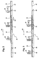
- a device 20 according to the invention which has a total of four conveyor platforms 21, 22, 23 and 24 arranged one behind the other.
- An arrow 25 visualizes a main conveying direction of the device 20 according to the invention
- Fig. 1 is in the main conveying direction forward conveyor platform 21 free or unoccupied.
- an aircraft engine 26, 27 and 28 is positioned in each case.
- the aircraft engines 26, 27 and 28 are moved by successively arranged workstations, wherein in the embodiment according to Fig. 1 the device 20 according to the invention is positioned in the region of a disassembly line, from which it follows that in the case of the Fig.
- the aircraft engines 26, 27 and 28 are decomposed in the movement through the successively arranged workstations in modules.
- the aircraft engines 26, 27 and 28 are decomposed in the movement through the successively arranged workstations in modules.
- four conveyor platforms 21, 22, 23 and 24 are provided, as well as four workstations are available. It is immediately obvious that the number of production platforms and workstations can be varied.
- Fig. 1 shows the rest position of the device 20 according to the invention, in which it is stationary. In this state, all conveyor platforms 21 to 24 lie in one plane. If the aircraft engines 26, 27 and 28 are now to be moved in the main conveying direction, the conveying platform 21 located in the main conveying direction is freed. This means that in the case where the device 20 according to the invention is arranged in a disassembly line of the aircraft engine, the disassembly of an aircraft engine into individual modules is completed in the region of the front workstation in which the forward conveyor platform 21 is located. After clearing the forward conveying conveyor 21 in the conveying direction, the same is lowered in the direction of the arrow 29.
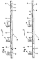
- the lowered conveyor platform 21 is then below the plane formed by the conveyor platforms 22, 23 and 24 in the resting state opposite to the main conveying direction in the direction of the arrow 30 (see Fig. 2 ) movable.
- a front section is released in the area of the front workstation.
- each of the conveyor platforms 22, 23 and 24 is moved forwards around a workstation in the main conveying direction.
- the conveyor platform 22 fills the section released from the originally forward conveyor platform 21.
- aircraft engines can be moved by a plurality of workstations arranged one behind the other, wherein the workstations can serve for the gradual disassembly, repair or assembly of the aircraft engines.
- the conveyor 20 enables a discontinuous movement of the aircraft engines in the main conveying direction, ie, the aircraft engines are moved by the workstations after a predetermined clock.
- the timing at which the aircraft engines are moved through the workstations or in which the conveyor platforms are moved is preferably sixteen hours or even twelve hours. Between two clock cycles, the device is stationary and is therefore in the idle state (see Fig. 1 ). Within these sixteen hours, respectively, twelve hours can work on the aircraft engines in the respective workstations are performed. In relation to the cycle time, the time required to move the aircraft engines or conveyor platforms is short. So takes a locomotion cycle in the sense of Fig. 1 to 5 in about twenty minutes.
- the device 20 according to the invention is embedded in a floor 33 of a workshop in such a way that the plane in which the conveyor platforms 21, 22, 23 and 24 are at rest lies in the plane of the floor 33.
- This can be special 6 and 7 such as Fig. 13 to 15 be removed. This ensures that a barrier-free access of the conveyor platforms 21, 22, 23 and 24 in the idle state of the same is possible. Workers who must therefore enter the conveyor platforms 21 to 24 to carry out disassembly or repair or assembly work, can enter from the floor 33 of the workshop the conveyor platforms 21 to 24 without obstructive steps. This increases the work safety.
- the device 20 has a first drive device in order to move the conveyor platforms 21 to 24 preferably together with aircraft engines 26, 27 and 28 positioned on the conveyor platforms 21 to 24 in the main conveying direction.
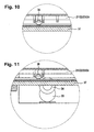
- the first drive means for moving the conveyor platforms 21 to 24 comprises a plurality of friction wheels 34. Such a friction wheel 34 is in Fig. 11 shown.
- the friction wheel 34 is driven by an associated motor 35 and transmits the driving power of the motor 35 to the conveyor platforms 21, 22, 23 and 24. In the area of each workstation at least one such friction wheel 34 is arranged. This ensures that, when the conveyor platforms 21 to 24 travel in the main conveying direction, at least one active friction wheel 34 is available for each conveyor platform 21 to 24.
- at least one of the friction wheels is provided on both sides of the conveyor platforms 21 to 24.
- the conveyor platforms 21 to 24 In order to enable a simple movement of the conveyor platforms 21 to 24 in the main conveying direction, the conveyor platforms 21 to 24, in particular along their longitudinal sides, a plurality of wheels 36 are assigned. These wheels are for example in 6 and 7 such as 10 and 11 shown. How best 10 and 11 can be removed, the wheels 36 are on guide rails 37 and guide rails, in particular to extend on both sides of the conveyor platforms 21 to 24. As a result, a secure guidance of the conveyor platforms 21 to 24 is ensured on the one hand, and on the other hand, the conveyor platforms 21 to 24 are movable with little resistance in the main conveying direction.
- the device 20 To move a lowered conveyor platform 21 opposite to the main conveying direction, the device 20 according to the invention has a second drive device.
- the second drive device is designed as a chain conveyor 38.
- the chain conveyor 38 is particularly in Fig. 6 to 9 shown.
- the chain conveyor 38 extends over the entire region of the workstations, which are arranged between the workstation lying in the main conveying direction and the workstation located behind in the conveying direction. In the area of the workstation located at the front in the main conveying direction as well as the workstation located at the rear in the main conveying direction, the chain conveyor 38 extends at least in sections. Show this 6 and 7 especially clear.
- the chain conveyor 38 comprises a conveyor chain 40 circulating in the direction of the arrows 39.
- Guide rollers 41 for the conveyor chain 40 are arranged in the region of the workstation at the front in the main conveying direction and in the workstation at the rear in the main conveying direction. Accordingly, a lowered conveying platform 21 below the other conveying platforms 22 to 24 is movable opposite to the main conveying direction via the chain conveyor 38.
- the first drive device for moving the conveyor platforms 21 to 24 in the main conveying direction should not exceed an acceleration value of approximately 2 m / min. Acceleration values of up to 4 m / min are possible for the second conveying device for moving lowered conveying platforms opposite to the main conveying direction.
- the second conveyor thus allows a faster movement of the conveyor platforms than the first conveyor.
- one of the friction wheels 34 is positioned in the region of the guide roller 41. So shows Fig. 8 in that a conveyor platform 21 to be moved into the region of the workstation located in the main conveying direction behind is just being detected by the corresponding friction wheel 34.
- Fig. 9 shows the same arrangement as Fig. 8 However, with a direction opposite to the main conveying direction in the main conveying direction behind moving workstation moving conveyor platform 21.
- the friction wheels 34 are therefore positioned at a front in the main conveying direction end of the respective workstations so that the conveyor platforms 21 to 24 over the entire distance to be covered with the friction wheels 34th stay in contact.
- the device 20 For lifting and lowering of conveyor platforms, which must be transported opposite to the main conveying direction, the device 20 according to the invention comprises lifting devices.
- a first lifting device 42 is positioned in the region of the workstation located in the main conveying direction.
- a second lifting device 43 is positioned in the area in the main conveying direction rear workstation.
- the first lifting device 42 is most clearly in Fig. 6 shown.
- the second lifting device 43 is in Fig. 7 shown in two different positions, namely in a first lowered position and in a second raised position.
- the lowering and lifting of the lifting devices 42, 43 takes place by means of the lifting devices 42, 43 associated lifting cylinders 44.
- the lifting cylinder 44 are preferably formed as a hydraulic cylinder.
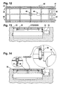
- the front in the main conveying direction lifting device 42 is in Fig. 12 shown in a view from below. Adjacent to the ground 33 (see Fig. 6 ) are assigned to the lifting device 42 at a first end 45 pivot bearing 46 and tilt bearings. About the pivot bearing 46, the lifting device 42 is pivotally attached to the first end 45 at the bottom 33 and tilted on actuation of the lifting cylinder 44 about the pivot bearing 46. The lifting device 42 has recesses 48 at an end 47 opposite the end 45. The chain conveyor 38 extends into the recesses 48. This ensures that a lowered conveying platform 21 can be detected directly by the chain conveyor 38. In order to avoid an uncontrolled movement of a lowered conveyor platform as a result of gravity, the lifting device 42 is associated in a central portion of a braking device 49 for a conveyor platform.
- Fig. 15 it is also within the meaning of the present invention to minimize gaps between the conveyor platforms 21, 22, 23, 24 and the floor 33 of the workshop.
- Fig. 15 For this purpose, between the actual conveyor platform 21 to 24 and the bottom 33 in the plane of the bottom 33 and the plane of the conveyor platforms 21 to 24 lying cover 50 is provided. The cover 50 covers a gap 51 between the work platforms 21 to 24 and the bottom 33. Falling tools or parts of an aircraft engine are therefore held up by the cover 50 and thus can not enter the gap 51.
- a surface of the conveyor platforms 21 to 24 is provided with a non-slip coating.
- lubricants or other fluids ie oil or kerosene
- the conveyor platforms 21 to 24 are preferably twelve meters long and four meters wide.
- Fig. 16 shows a perspective view of a production platform 21 to 24 with an aircraft engine 26 to 28 positioned on the production platform.
- the aircraft engine is held on the production platform by an adapter 52.
- the adapter 52 is mounted in a receiving area 53 of the conveyor platform.
- the adapter 52 has a total of four supports 54. In each case two of these supports 54 are arranged to one side of the aircraft engine. The position and the distance of the supports 54 to each other in the receiving area 53 is individually adaptable to the respective type of aircraft engine. This makes it possible that in the conveyor platforms 21 to 24 different types of aircraft engines can be included.
- the supports 54 are associated with a front portion of the engine. A rear portion of the engine is supported by two conventional supports 55.
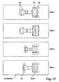
- Fig. 17 makes clear that 21 to 24 different types of engines can be positioned on the conveyor platforms. So shows Fig. 17 four production platforms, wherein on each of these conveyor platforms, a different aircraft engine TWK 1, TWK2, TWK3 or TWK4 is arranged.
- the types of aircraft engines are standard engines and familiar to those skilled in the art.
- Fig. 17 visualizes the different spatial dimensions of the different types of aircraft engines and their different application of force to the conveyor platforms 21 to 24.
- Fig. 17 can be taken that both the front supports 54 and the rear supports 55 can be arranged in different positions on the conveyor platforms 21 to 24.
- the device according to the invention enables a reliable and safe movement of serviced aircraft engines by successively arranged workstations. With the aid of the device according to the invention, servicing or maintenance of aircraft engines according to the so-called assembly line principle is possible. With the aid of the device according to the invention, the method according to the invention can be carried out.
- the device according to the invention is structurally simple. It is inexpensive to implement.
Landscapes
- Engineering & Computer Science (AREA)
- Mechanical Engineering (AREA)
- Automatic Assembly (AREA)
- Control Of Turbines (AREA)
- Testing Of Engines (AREA)
- Intermediate Stations On Conveyors (AREA)
- Filling Or Discharging Of Gas Storage Vessels (AREA)
- Crystals, And After-Treatments Of Crystals (AREA)
Description
- Die Erfindung betrifft eine Vorrichtung zum Fortbewegen von Gasturbinen nach dem Oberbegriff des Anspruchs 1, d.h. von Flugzeugtriebwerken oder stationären Gasturbinen, oder von Modulen derselben, insbesondere bei der Wartung, sowie ein entsprechendes Verfahren.
- Der Wartung bzw. Instandhaltung, insbesondere Reparatur, von Gasturbinen, insbesondere Flugzeugtriebwerken, kommt bei der Ermittlung der direkten Betriebskosten eines Flugszeugs eine entscheidende Rolle zu. So sind in etwa 30 % der direkten Betriebskosten eines Flugzeugs den Flugzeugtriebwerken zuzuordnen, wobei in etwa ein Drittel der die Triebwerke betreffenden Betriebskosten auf die Instandhaltung der Flugzeugtriebwerke entfällt. Insofern machen die Kosten für die Instandhaltung von Flugzeugtriebwerken in etwa 10 % der gesamten direkten Betriebskosten eines Flugzeugs aus. Hieraus folgt unmittelbar, dass eine effiziente und kostengünstige Instandhaltung bzw. Wartung und Reparatur von Flugzeugtriebwerken für Fluggesellschaften von entscheidender Bedeutung ist. Ähnliches gilt auch für stationäre Gasturbinen.
- Bislang wurde bei der Instandhaltung bzw. Wartung von Gasturbinen, insbesondere Flugzeugtriebwerken, nach dem sogenannten Werkstattprinzip vorgegangen. Bei dem sogenannten Werkstattprinzip verbleibt die Gasturbine bzw. das Flugzeugtriebwerk zumindest in Teilen an einer Position bzw. an einem Ort. Benötigtes Arbeitsmaterial, benötigte Arbeitswerkzeuge sowie benötigtes Arbeitspersonal werden zeitlich so an die Gasturbine herangeführt, dass möglichst wenige Störungen auftreten und eine zugesagte Instandhaltungszeit eingehalten werden kann.
- Die Instandhaltung bzw. Wartung von Gasturbinen, insbesondere von Flugzeugtriebwerken, nach dem sogenannten Werkstattprinzip verfügt jedoch über den Nachteil, dass die Instandhaltung keiner definierten Prozessstruktur folgt. Vielmehr werden Arbeiten an der Gasturbine bzw. am Flugzeugtriebwerk in nahezu beliebiger Reihenfolge durchgeführt, wodurch sich insbesondere dann, wenn gleichzeitig mehrere Gasturbinen gewartet werden, Störungen und Verzögerungen bei der Wartung ergeben können. Eine Wartung von Gasturbinen nach dem sogenannten Werkstattprinzip verfügt demnach über die Nachteile, dass einerseits keine klare Prozessstruktur besteht und dass andererseits lange Zeiten für die Wartung bzw. Instandhaltung benötigt werden. Dies beeinträchtigt die Effizienz der Wartung.
- Auch bei der Neuproduktion von Gasturbinen ist eine effiziente Fortbewegung wünschenswert.
- Ein Vorrichtung zum Fortbewegen von Trägern oder Förderplattformen ist bereits aus
EP-A-1 106 541 bekannt. - Hiervon ausgehend liegt der vorliegenden Erfindung das Problem zu Grunde, eine neuartige Vorrichtung und ein neuartiges Verfahren zum Fortbewegen von Gasturbinen, insbesondere Flugzeugtriebwerken, zu schaffen.
- Dieses Problem wird durch eine Vorrichtung mit den Merkmalen des Patentanspruchs 1 gelöst.
- Die erfindungsgemäße Vorrichtung zum Fortbewegen von Gasturbinen, insbesondere bei der Wartung derselben, ermöglicht die Wartung bzw. Instandhaltung von Gasturbinen nach einem sogenannten Fließbandprinzip vorzunehmen. Es ist eine grundlegende Erkenntnis der hier vorliegenden Erfindung, dass das Fließbandprinzip auch für Wartungsarbeiten bzw. Instandhaltungsarbeiten an Gasturbinen geeignet ist. Die erfindungsgemäße Vorrichtung ermöglicht eine hohe Effizienz bei der Wartung von Gasturbinen und eine kurze Wartungszeit. Die erfindungsgemäße Vorrichtung kann auch bei der Neuproduktion von Flugzeugtriebwerken eingesetzt werden.
- Nach einer vorteilhaften Weiterbildung der Erfindung verfügt die erfindungsgemäße Vorrichtung über eine erste Antriebseinrichtung, um die Förderplattformen vorzugsweise zusammen mit auf den Förderplattformen positionierten Gasturbinen in einer Hauptförderrichtung durch hintereinander angeordnete Arbeitsstationen zu bewegen, und über eine zweite Antriebseinrichtung, um die Förderplattformen entgegengesetzt zu einer Hauptförderrichtung der Gasturbinen zu bewegen. Diese Ausgestaltung der erfindungsgemäßen Vorrichtung ist konstruktiv besonders einfach und erlaubt eine sichere Bewegung der Flugzeugtriebwerke.
- Die erfindungsgemäße Vorrichtung ist derart in einen Boden einer Werkhalle eingelassen, dass die Ebene, in der die Förderplattformen in einem Ruhezustand liegen, in der Ebene des Bodens liegt, derart, dass die Förderplattformen barrierefrei zugänglich sind. Dies ist aus Sicherheitsgründen besonders vorteilhaft.
- Das erfindungsgemäße Verfahren ist durch die Merkmale des unabhängigen Patentanspruchs 13 gekennzeichnet.
- Bevorzugte Weiterbildungen der Erfindung ergeben sich aus den abhängigen Unteransprüchen und der nachfolgenden Beschreibung.
- Ein Ausführungsbeispiel der Erfindung wird, ohne hierauf beschränkt zu sein, an Hand der Zeichnung näher erläutert. In der Zeichnung zeigt:
- Fig. 1:
- eine schematisierte Seitenansicht einer erfindungsgemäßen Vorrichtung zum Fortbewegen von Flugzeugtriebwerken oder von Modulen der Flugzeugtriebwerke bei der Wartung derselben, mit drei auf der Vorrichtung positionierten Flugzeugtriebwerken, in einem ersten Zustand;
- Fig. 2:
- die Vorrichtung gemäß
Fig. 1 in einem zweiten Zustand; - Fig. 3:
- die Vorrichtung gemäß
Fig. 1 ,2 in einem dritten Zustand; - Fig. 4:
- die Vorrichtung gemäß
Fig. 1 bis 3 in einem vierten Zustand; - Fig. 5:
- die Vorrichtung gemäß
Fig. 1 bis 4 in einem fünften Zustand; - Fig. 6:
- ein vergrößertes Detail der Vorrichtung gemäß
Fig. 1 bis 5 in schematisierter Seitenansicht; - Fig. 7:
- ein anderes vergrößertes Detail der Vorrichtung gemäß
Fig. 1 bis 5 in schematisierter Seitenansicht; - Fig. 8;
- ein weiteres Detail der Vorrichtung gemäß
Fig. 1 bis 5 in schematisierter Seitenansicht; - Fig. 9:
- das Detail gemäß
Fig. 8 in einem zweiten Zustand; - Fig. 10:
- ein weiteres Detail der Vorrichtung gemäß
Fig. 1 bis 5 in schematisierter Seitenansicht; - Fig. 11:
- eine weiteres Detail der Vorrichtung gemäß
Fig. 1 bis 5 in schematisierter Seitenansicht; - Fig. 12:
- eine Hubeinrichtung der erfindungsgemäßen Vorrichtung gemäß
Fig. 1 bis 5 in schematisierter Ansicht von unten; - Fig. 13:
- einen Querschnitt durch die erfindungsgemäße Vorrichtung;
- Fig. 14:
- ein Detail des Querschnitts gemäß
Fig. 13 ; - Fig. 15:
- ein weiteres Detail des Querschnitts gemäß
Fig. 13 ; - Fig. 16:
- eine stark schematisierte, perspektivische Ansicht eines Ausschnitts der erfindungsgemäßen Vorrichtung; und
- Fig. 17:
- unterschiedliche, auf der erfindungsgemäßen Vorrichtung positionierbare Typen von Flugzeugtriebwerken.
- Die erfindungsgemäße Vorrichtung sowie das erfindungsgemäße Verfahren zum Fortbewegen von Gasturbinen werden nachfolgend unter Bezugnahme auf
Fig. 1 bis 17 am Beispiel von Flugzeugtreibwerken im Detail beschrieben. Die erfindungsgemäße Vorrichtung dient der Fortbewegung bzw. dem Transportieren von Flugzeugtriebwerken oder von Modulen der Flugzeugtriebwerke bei der Wartung bzw. Instandhaltung derselben. - Es soll nochmals darauf hingewiesen werden, dass sich die erfindungsgemäße Vorrichtung und das Verfahren auch bei der Neuproduktion von Gasturbinen, insbesondere Flugzeugtriebwerken, einsetzen lassen.
- Die Wartung bzw. Instandhaltung umfasst die Demontage des Flugzeugtriebwerks in Module und/oder Baugruppen und/oder Einzelteile, die Inspektion sowie gegebenenfalls Reparatur der Module und/oder Baugruppen und/oder Einzelteile sowie die anschließende Montage eines Flugzeugtriebwerks aus inspizierten und/oder repartierten und/oder neuen Modulen und/oder Baugruppen und/oder Einzelteilen. Die erfindungsgemäße Vorrichtung eignet sich insbesondere zum Fortbewegen der Flugzeugtriebwerke bei der Demontage der Flugzeugtriebwerke in Module sowie bei der modulweisen Montage eines Flugzeugtriebwerks. Die erfindungsgemäße Vorrichtung kann jedoch auch bei der Demontage sowie Montage der Module oder Baugruppen des Flugzeugtriebwerks eingesetzt werden. Auch ist prinzipiell vorstellbar, eine solche Vorrichtung bei der eigentlichen Reparatur zu verwenden.
- Unter Bezugnahme auf
Fig. 1 bis 5 soll nachfolgend zuerst das Prinzip der erfindungsgemäßen Vorrichtung sowie das erfindungsgemäße Verfahren zum Fortbewegen von Flugzeugtriebwerken bei der Wartung derselben beschrieben werden. - So zeigen
Fig. 1 bis 5 eine erfindungsgemäße Vorrichtung 20, die insgesamt vier hintereinander angeordnete Förderplattformen 21, 22, 23 und 24 aufweist. Ein Pfeil 25 visualisiert eine Hauptförderrichtung der erfindungsgemäßen Vorrichtung 20. InFig. 1 ist die in Hauptförderrichtung vorn liegende Förderplattform 21 frei bzw. unbesetzt. Auf den hinter der vorne liegenden Förderplattform 21 positionierten Förderplattformen 22, 23 und 24 ist jeweils ein Flugzeugtriebwerk 26, 27 und 28 positioniert. Mithilfe der erfindungsgemäßen Vorrichtung 20 werden die Flugzeugtriebwerke 26, 27 und 28 durch hintereinander angeordnete Arbeitsstationen bewegt, wobei beim Ausführungsbeispiel gemäßFig. 1 die erfindungsgemäße Vorrichtung 20 im Bereich einer Demontagelinie positioniert ist, woraus folgt, dass bei dem inFig. 1 gezeigten Ausführungsbeispiel die Flugzeugtriebwerke 26, 27 und 28 bei der Bewegung durch die hintereinander angeordneten Arbeitsstationen in Module zerlegt werden. Sind, wie inFig. 1 dargestellt, vier Förderplattformen 21, 22, 23 und 24 vorgesehen, so sind auch vier Arbeitsstationen vorhanden. Es ist unmittelbar einleuchtend, dass die Anzahl der Förderplattformen sowie Arbeitsstationen variiert werden kann. -
Fig. 1 zeigt die Ruheposition der erfindungsgemäßen Vorrichtung 20, in der dieselbe still steht. In diesem Zustand liegen sämtliche Förderplattformen 21 bis 24 in einer Ebene. Sollen nun die Flugzeugtriebwerke 26, 27 und 28 in Hauptförderrichtung bewegt werden, so wird die in Hauptförderrichtung vorne liegende Förderplattform 21 freigeräumt. Dies bedeutet, dass in dem Fall, in dem die erfindungsgemäße Vorrichtung 20 in einer Demontagelinie des Flugzeugtriebwerks angeordnet ist, im Bereich der vorne liegenden Arbeitsstation, in welcher sich die vorne liegende Förderplattform 21 befindet, die Demontage eines Flugtriebwerks in einzelne Module abgeschlossen ist. Nach dem Freiräumen der in Förderrichtung vorne liegenden Förderplattform 21 wird dieselbe im Sinne des Pfeils 29 abgesenkt. - Die abgesenkte Förderplattform 21 ist sodann unterhalb der von den Förderplattformen 22, 23 und 24 im Ruhezustand gebildeten Ebene entgegengesetzt zur Hauptförderrichtung im Sinne des Pfeils 30 (siehe
Fig. 2 ) bewegbar. Durch das Absenken sowie nach hinten Bewegen der ursprünglich in Hauptförderrichtung vorne liegenden Förderplattform 21 wird ein vorderer Abschnitt im Bereich der vorne liegenden Arbeitsstation freigegeben. - Die hinter der abgesenkten sowie entgegengesetzt zur Hauptförderrichtung bewegten Förderplattform 21 angeordneten Förderplattformen 22, 23 und 24 sind sodann in Hauptförderrichtung nach vorne bewegbar. Dies kann insbesondere
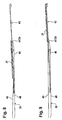
Fig. 3 entnommen werden. Hierdurch wird jede der Förderplattformen 22, 23 und 24 um eine Arbeitsstation in Hauptförderrichtung nach vorne bewegt. Die Förderplattform 22 füllt hierdurch den von der ursprünglich vorne liegenden Förderplattform 21 freigegebenen Abschnitt aus. Dadurch, dass jede der hintereinander angeordneten Förderplattformen 22, 23 und 24 um eine Arbeitsstation nach vorne bewegt wird, wird die in Hauptförderrichtung hinten liegende Arbeitsstation freigegeben, d.h. die ursprünglich in Hauptförderrichtung hinten liegende Förderplattform 24 gibt einen Abschnitt innerhalb einer ebenfalls hinten liegenden Arbeitsstation frei. Bei Bewegung der Förderplattformen 22, 23 und 24 in Hauptförderrichtung verbleibt die abgesenkte sowie zuvor entgegengesetzt zur Hauptförderrichtung bewegte Förderplattform 21 in ihrer Position. - Durch eine weitere Bewegung der abgesenkten Förderplattform 21 entgegengesetzt zur Hauptförderrichtung gemäß Pfeil 31 und nachfolgendes Anheben derselben gemäß Pfeil 32 ist die abgesenkte sowie ursprünglich vorne liegende Förderplattform 21 in den von der ursprünglich hinten liegenden Förderplattform 24 freigegebenen Abschnitt innerhalb der hinten liegenden Arbeitsstation einbringbar. Dieser Abschnitt wird demnach von der Plattform 21 besetzt. Dies kann insbesondere
Fig. 4 und 5 entnommen werden. In dem Bereich der in Hauptförderrichtung hinten liegenden Arbeitsstation ist dann auf der Förderplattform 21 wiederum ein Flugzeugtriebwerk positionierbar. In der in Hauptförderrichtung hinten liegenden Arbeitsstation wird demnach mit der modulweisen Demontage der Flugzeugtriebwerke begonnen. - Mithilfe der erfindungsgemäßen Vorrichtung sind demzufolge Flugzeugtriebwerke durch mehrere hintereinander angeordnete Arbeitsstationen bewegbar, wobei die Arbeitsstationen der schrittweisen Demontage, Reparatur oder auch Montage der Flugzeugtriebwerke dienen können. Die Fördereinrichtung 20 ermöglicht eine diskontinuierliche Bewegung der Flugzeugtriebwerke in Hauptförderrichtung, d.h., die Flugzeugtriebwerke werden nach einem vorgegebenen Takt durch die Arbeitsstationen bewegt. Der Takt, in dem die Flugzeugtriebwerke durch die Arbeitsstationen bewegt werden bzw. in dem die Förderplattformen bewegt werden, beträgt vorzugsweise sechszehn Stunden oder auch zwölf Stunden. Zwischen zwei Taktzyklen steht die Vorrichtung still und befindet sich demnach im Ruhezustand (siehe
Fig. 1 ). Innerhalb dieser sechszehn Stunden bzw, zwölf Stunden können Arbeiten an den Flugzeugtriebwerken in den jeweiligen Arbeitsstationen durchgeführt werden. Im Verhältnis zur Taktzeit ist die Zeit, die zur Fortbewegung der Flugzeugtriebwerke bzw. Förderplattformen benötigt wird, kurz. So dauert ein Fortbewegungszyklus im Sinne derFig. 1 bis 5 in etwa zwanzig Minuten. - Die erfindungsgemäße Vorrichtung 20 ist derart in einen Boden 33 einer Werkhalle eingelassen, dass die Ebene, in der die Förderplattformen 21, 22, 23 und 24 im Ruhezustand liegen, in der Ebene des Bodens 33 liegt. Dies kann insbesondere
Fig. 6 und 7 sowieFig. 13 bis 15 entnommen werden. Hierdurch ist sichergestellt, dass ein barrierefreier Zugang der Förderplattformen 21, 22, 23 und 24 im Ruhezustand derselben möglich ist. Arbeiter, die demnach zur Durchführung von Demontage- oder Reparatur- oder Montagearbeiten die Förderplattformen 21 bis 24 betreten müssen, können ausgehend vom Boden 33 der Werkhalle die Förderplattformen 21 bis 24 ohne hinderliche Stufen betreten. Dies erhöht die Arbeitssicherheit. - Die erfindungsgemäße Vorrichtung 20 verfügt über eine erste Antriebseinrichtung, um die Förderplattformen 21 bis 24 vorzugsweise zusammen mit auf den Förderplattformen 21 bis 24 positionierten Flugzeugtriebwerken 26, 27 und 28 in Hauptförderrichtung zu bewegen. Die erste Antriebseinrichtung zur Bewegung der Förderplattformen 21 bis 24 umfasst mehrere Reibräder 34. Ein derartiges Reibrad 34 ist in
Fig. 11 dargestellt. Das Reibrad 34 wird von einem zugeordneten Motor 35 angetrieben und überträgt die Antriebsleistung des Motors 35 auf die Förderplattformen 21, 22, 23 und 24. Im Bereich jeder Arbeitsstation ist mindestens ein derartiges Reibrad 34 angeordnet. Hierdurch ist sichergestellt, dass bei Fortbewegung der Förderplattformen 21 bis 24 in Hauptförderrichtung für jede Förderplattform 21 bis 24 mindestens ein aktives Reibrad 34 bereitsteht. Vorzugsweise ist zu beiden Seiten der Förderplattformen 21 bis 24 mindestens eines der Reibräder vorgesehen. - Um eine einfache Bewegung der Förderplattformen 21 bis 24 in Hauptförderrichtung zu ermöglichen, sind den Förderplattformen 21 bis 24 insbesondere entlang ihrer Längsseiten mehrere Laufräder 36 zugeordnet. Diese Laufräder sind zum Beispiel in
Fig. 6 und 7 sowieFig. 10 und 11 gezeigt. Wie am bestenFig. 10 und 11 entnommen werden kann, liegen die Laufräder 36 auf Führungsschienen 37 bzw. Führungsleisten auf, die sich insbesondere zu beiden Seiten der Förderplattformen 21 bis 24 erstrecken. Hierdurch wird einerseits eine sichere Führung der Förderplattformen 21 bis 24 gewährleistet und andererseits sind die Förderplattformen 21 bis 24 mit geringem Widerstand in Hauptförderrichtung bewegbar. - Zur Bewegung einer abgesenkten Förderplattform 21 entgegengesetzt zur Hauptförderrichtung verfügt die erfindungsgemäße Vorrichtung 20 über eine zweite Antriebseinrichtung. Die zweite Antriebseinrichtung ist als Kettenförderer 38 ausgebildet. Der Kettenförderer 38 ist insbesondere in
Fig. 6 bis 9 dargestellt. - Der Kettenförderer 38 erstreckt sich über den gesamten Bereich der Arbeitsstationen, die zwischen der in Hauptförderrichtung vorne liegenden Arbeitsstation sowie der in Förderrichtung hinten liegenden Arbeitsstation angeordnet sind. In dem Bereich der in Hauptförderrichtung vorne liegenden Arbeitsstation sowie der in Hauptförderrichtung hinten liegenden Arbeitsstation erstreckt sich der Kettenförderer 38 zumindest abschnittsweise. Dies zeigen
Fig. 6 und 7 besonders deutlich. Der Kettenförderer 38 umfasst eine im Sinne der Pfeile 39 umlaufende Förderkette 40. Umlenkrollen 41 für die Förderkette 40 sind im Bereich der in Hauptförderrichtung vorne liegenden Arbeitsstation sowie der in Hauptförderrichtung hinten liegenden Arbeitsstation angeordnet. Über den Kettenförderer 38 ist demnach eine abgesenkte Förderplattform 21 unterhalb der übrigen Förderplattformen 22 bis 24 entgegengesetzt zur Hauptförderrichtung bewegbar. - An dieser Stelle sei angemerkt, dass die erste Antriebseinrichtung zur Bewegung der Förderplattformen 21 bis 24 in Hauptförderrichtung einen Beschleunigungswert von ca. 2 m/min nicht überschreiten sollte. Für die zweite Fördereinrichtung zur Bewegung abgesenkter Förderplattformen entgegengesetzt zur Hauptförderrichtung sind Beschleunigungswerte von bis zu 4 m/min möglich. Die zweite Fördereinrichtung erlaubt demnach eine schnellere Fortbewegung der Förderplattformen als die erste Fördereinrichtung.
- Wie insbesondere
Fig. 8 und 9 entnommen werden kann, ist im Bereich der Umlenkrolle 41 auch eines der Reibräder 34 positioniert. So zeigtFig. 8 , wie eine in den Bereich der in Hauptförderrichtung hinten liegenden Arbeitsstation zu bewegende Förderplattform 21 gerade vom entsprechenden Reibrad 34 erfasst wird.Fig. 9 zeigt dieselbe Anordnung wieFig. 8 , jedoch mit einem entgegengesetzt zur Hauptförderrichtung in die in Hauptförderrichtung hinten liegende Arbeitsstation hineinbewegter Förderplattform 21. Die Reibräder 34 sind demzufolge an einem in Hauptförderrichtung vorne liegenden Ende der jeweiligen Arbeitsstationen positioniert, damit die Förderplattformen 21 bis 24 über die gesamte zurückzulegende Strecke mit den Reibrädern 34 in Kontakt stehen. - Zum Anheben sowie zum Absenken von Förderplattformen, die entgegengesetzt zur Hauptförderrichtung transportiert werden müssen, umfasst die erfindungsgemäße Vorrichtung 20 Hubeinrichtungen. Eine erste Hubeinrichtung 42 ist im Bereich der in Hauptförderrichtung vorliegenden Arbeitsstation positioniert. Eine zweite Hubeinrichtung 43 ist im Bereich in Hauptförderrichtung hinten liegenden Arbeitsstation positioniert. Die erste Hubeinrichtung 42 ist am deutlichsten in
Fig. 6 dargestellt. Die zweite Hubeinrichtung 43 ist inFig. 7 in zwei unterschiedlichen Positionen dargestellt, nämlich in einer ersten abgesenkten Position sowie in einer zweiten hochgefahrenen Position. Das Absenken sowie Anheben der Hubeinrichtungen 42, 43 erfolgt mithilfe von den Hubeinrichtungen 42, 43 zugeordneten Hubzylindern 44. Die Hubzylinder 44 sind vorzugsweise als Hydraulikzylinder ausgebildet. - Die in Hauptförderrichtung vorne liegende Hubeinrichtung 42 ist in
Fig. 12 in einer Ansicht von unten dargestellt. Benachbart zum Boden 33 (sieheFig. 6 ) sind der Hubeinrichtung 42 an einem ersten Ende 45 Drehlager 46 bzw. Kipplager zugeordnet. Über die Drehlager 46 ist die Hubeinrichtung 42 mit dem ersten Ende 45 schwenkbar am Boden 33 befestigt und auf Betätigung des Hubzylinders 44 um die Drehlager 46 kippbar. An einem dem Ende 45 gegenüberliegenden Ende 47 verfügt die Hubeinrichtung 42 über Ausnehmungen 48. In die Ausnehmungen 48 erstreckt sich der Kettenförderer 38. Hierdurch ist sichergestellt, dass eine abgesenkte Förderplattform 21 unmittelbar vom Kettenförderer 38 erfasst werden kann. Um eine unkontrollierte Bewegung einer abgesenkten Förderplattform in Folge der Schwerkraft zu vermeiden, ist der Hubeinrichtung 42 in einem mittleren Abschnitt eine Bremseinrichtung 49 für eine Förderplattform zugeordnet. - Es liegt weiterhin im Sinne der hier vorliegenden Erfindung, Spalte zwischen den Förderplattformen 21, 22, 23, 24 und dem Boden 33 der Werkhalle zu minimieren. Dies kann insbesondere
Fig. 15 entnommen werden. Hierdurch soll sichergestellt werden, dass dann, wenn Arbeiter zur Durchführung von Arbeitsschritten an den Flugzeugtriebwerken die Förderplattformen 21 bis 24 betreten, weder Werkzeuge noch demontierte Teile des Flugzeugtriebwerks durch Spalte in einen Bereich unterhalb der Förderplattformen 21 bis 24 fallen können. GemäßFig. 15 ist hierzu zwischen der eigentlichen Förderplattform 21 bis 24 und dem Boden 33 eine in der Ebene des Bodens 33 bzw. der Ebene der Förderplattformen 21 bis 24 liegende Abdeckung 50 vorgesehen. Die Abdeckung 50 überdeckt einen Spalt 51 zwischen den Arbeitsplattformen 21 bis 24 und dem Boden 33. Herabfallende Werkzeuge bzw. Teile eines Flugzeugtriebwerks werden demnach von der Abdeckung 50 aufgehalten und können so nicht in den Spalt 51 gelangen. - Nach einem weiteren Aspekt der hier vorliegenden Erfindung ist eine Oberfläche der Förderplattformen 21 bis 24 mit einer rutschsicheren Beschichtung versehen. Bei der Demontage bzw. sonstigen Arbeiten am Flugzeugtriebwerk können aus dem Flugzeugtriebwerk Schmierstoffe oder andere Flüssigkeiten, also Öl oder Kerosin, austreten. Durch den rutschhemmenden Belag auf der Oberfläche der Förderplattformen 21 bis 24 ist dann sichergestellt, dass selbst dann, wenn Öl oder Kerosin aus dem Flugzeugtriebwerk austreten, Arbeiter einen sicheren Stand auf der Förderplattform haben. Die Förderplattformen 21 bis 24 sind vorzugsweise zwölf Meter lang und vier Meter breit.
-
Fig. 16 zeigt eine perspektivische Ansicht einer Förderplattform 21 bis 24 mit einem auf der Förderplattform positionierten Flugzeugtriebwerk 26 bis 28. Das Flugzeugtriebwerk wird auf der Förderplattform durch einen Adapter 52 gehalten. Der Adapter 52 ist in einem Aufnahmebereich 53 der Förderplattform montiert. Der Adapter 52 verfügt über insgesamt vier Stützen 54. Jeweils zwei dieser Stützen 54 sind zu einer Seite des Flugzeugtriebwerks angeordnet. Die Position sowie der Abstand der Stützen 54 zueinander im Aufnahmebereich 53 ist an den jeweiligen Typ des Flugzeugtriebwerks individuell anpassbar. Hierdurch wird ermöglicht, dass in den Förderplattformen 21 bis 24 unterschiedliche Typen von Flugzeugtriebwerken aufgenommen werden können. Die Stützen 54 sind einem vorderen Bereich des Triebwerks zugeordnet. Ein hinterer Bereich des Triebwerks wird durch zwei konventionelle Stützen 55 abgestützt. -
Fig. 17 verdeutlicht, dass auf den Förderplattformen 21 bis 24 unterschiedliche Triebwerkstypen positioniert werden können. So zeigtFig. 17 vier Förderplattformen, wobei auf jeder dieser Förderplattformen ein unterschiedliches Flugzeugtriebwerk TWK 1, TWK2, TWK3 oder TWK4 angeordnet ist. Die Typen von Flugzeugtriebwerken sind Serientriebwerke und dem Fachmann geläufig.Fig. 17 visualisiert die unterschiedlichen räumlichen Abmessungen der unterschiedlichen Typen von Flugzeugtriebwerken sowie deren unterschiedliche Krafteinleitung auf die Förderplattformen 21 bis 24. Weiterhin kannFig. 17 entnommen werden, dass sowohl die vorderen Stützen 54 als auch die hinteren Stützen 55 in unterschiedlicher Position auf den Förderplattformen 21 bis 24 angeordnet werden können. - Die erfindungsgemäße Vorrichtung ermöglicht eine zuverlässige sowie sichere Bewegung von zu wartenden Flugzeugtriebwerken durch hintereinander angeordnete Arbeitsstationen. Mithilfe der erfindungsgemäßen Vorrichtung ist eine Wartung bzw. Instandhaltung von Flugzeugtriebwerken nach dem sogenannten Fließbandprinzip möglich. Mithilfe der erfindungsgemäßen Vorrichtung ist das erfindungsgemäße Verfahren ausführbar. Die erfindungsgemäße Vorrichtung ist konstruktiv einfach. Sie ist kostengünstig realisierbar.
-
- Vorrichtung
- 20
- Förderplattform
- 21
- Förderplattform
- 22
- Förderplattform
- 23
- Förderplattform
- 24
- Pfeil
- 25
- Flugzeugtriebwerk
- 26
- Flugzeugtriebwerk
- 27
- Flugzeugtriebwerk
- 28
- Pfeil
- 29
- Pfeil
- 30
- Pfeil
- 31
- Pfeil
- 32
- Boden
- 33
- Reibrad
- 34
- Motor
- 35
- Laufrad
- 36
- Führungsschiene
- 37
- Kettenförderer
- 38
- Pfeil
- 39
- Förderkette
- 40
- Umlenkrolle
- 41
- Hubeinrichtung
- 42
- Hubeinrichtung
- 43
- Hubzylinder
- 44
- Ende
- 45
- Drehlager
- 46
- Ende
- 47
- Ausnehmung
- 48
- Bremseinrichtung
- 49
- Abdeckung
- 50
- Schlitz
- 51
- Adapter
- 52
- Aufnahmebereich
- 53
- Stütze
- 54
- Stütze
- 55
Claims (16)
- Vorrichtung zum Fortbewegen von Gasturbinen, insbesondere Flugzeugtriebwerken (26, 27, 28), oder Modulen von Gasturbinen, insbesondere bei der Wartung derselben, mit mehreren hintereinander angeordneten Förderplattformen (21, 22, 23, 24), wobei auf jeder der Förderplattformen mindestens eine Gasturbine positioniert werden kann, und wobei die oder jede Gasturbine durch Bewegung der Förderplattformen (21, 22, 23, 24) bewegbar ist, dadurch gekennzeichnet, dass die Vorrichtung derart in einen Boden (33) einer Werkhalle eingelassen ist, dass die Ebene, in der die Förderplattformen (21, 22, 23, 24) im Ruhezustand liegen, in der Ebene des Bodens liegt, derart, dass die Förderplattformen barrierefrei zugänglich sind.
- Vorrichtung nach Anspruch 1, gekennzeichnet durch eine erste Antriebseinrichtung, um die Förderplattformen (21, 22, 23, 24) vorzugsweise zusammen mit einer auf den Förderplattformen positionierten Gasturbine in einer Hauptförderrichtung (25) durch hintereinander angeordnete Arbeitsstationen zu bewegen
- Vorrichtung nach Anspruch 1 oder 2, gekennzeichnet durch eine zweite Antriebseinrichtung, um die Förderplattformen (21, 22, 23, 24) entgegengesetzt zu einer Hauptförderrichtung (25) der Gasturbinen zu bewegen.
- Vorrichtung nach einem oder mehreren der Ansprüche 1 bis 3, dadurch gekennzeichnet, dass die Förderplattformen (21, 22, 23, 24) im Ruhezustand in einer Ebene liegen.
- Vorrichtung nach Anspruch 4, dadurch gekennzeichnet, dass zur Bewegung der Förderplattformen (21, 22, 23, 24) in einer Hauptförderrichtung der Gasturbinen eine in Hauptförderrichtung vorn liegende Förderplattform (21) absenkbar und unterhalb der Ebene entgegengesetzt zur Hauptförderrichtung bewegbar ist, so dass ein vorderer Abschnitt freigegeben und hinter der abgesenkten Förderplattform (21) angeordnete Förderplattformen (22, 23, 24) in Hauptförderrichtung bewegbar sind.
- Vorrichtung nach Anspruch 5, dadurch gekennzeichnet, dass die abgesenkte und unterhalb der Ebene entgegengesetzt zur Hauptförderrichtung bewegte Förderplattform (21) nach Fortbewegung der übrigen Förderplattformen (22, 23, 24) in Hauptförderrichtung derart anhebbar ist, dass ein von einer hinteren Förderplattform (24) freigegebener Abschnitt besetzbar ist.
- Vorrichtung nach einem oder mehreren der Ansprüche 1 bis 6, dadurch gekennzeichnet, dass eine erste Antriebseinrichtung zur Bewegung der Förderplattformen (21, 22, 23, 24) in der Hauptförderrichtung (25) mehrere Reibräder (34) umfasst, wobei die Reibräder (34) derart angeordnet sind, dass jede in Hauptförderrichtung zur bewegende Förderplattform (21, 22, 23, 24) mit mindestens einem Reibrad (34) in Kontakt steht.
- Vorrichtung nach einem oder mehreren der Ansprüche 1 bis 7, dadurch gekennzeichnet, dass das eine zweite Antriebseinrichtung zur Bewegung einer Förderplattform (21, 22, 23, 24) entgegengesetzt zur Hauptförderrichtung als Kettenförderer (38) ausgebildet ist.
- Vorrichtung nach einem oder mehreren der Ansprüche 1 bis 8, gekennzeichnet durch Hubeinrichtungen (42, 43) zum Absenken bzw. Anheben der Förderplattformen, wobei eine erste Hubeinrichtung (42) im Bereich einer ersten, vorn liegenden Arbeitsstation und eine zweite Hubeinrichtung (43) im Bereich einer zweiten, hinten liegenden Arbeitsstation angeordnet ist.
- Vorrichtung nach einem oder mehreren der Ansprüche 1 bis 9, dadurch gekennzeichnet, dass eine Oberfläche der Förderplattformen (21, 22, 23, 24) eine rutschsichere Beschichtung aufweist.
- Vorrichtung nach einem oder mehreren der Ansprüche 1 bis 10, dadurch gekennzeichnet, dass Spalte (51) zwischen den Förderplattformen (21, 22, 23, 24) und einem Boden (33) derart minimiert sind, dass weder Werkzeuge noch Teile einer Gasturbine durch die Spalte in einen Bereich unterhalb der Förderplattformen (21, 22, 23, 24) fallen können.
- Vorrichtung nach einem oder mehreren der Ansprüche 1 bis 11, dadurch gekennzeichnet, dass die Förderplattformen (21, 22, 23, 24) diskontinuierlich, vorzugsweise nach einem Takt, bewegbar sind.
- Verfahren zum Fortbewegen von Gasturbinen, insbesondere Flugzeugtriebwerken (26,27,28), oder Modulen von Gasturbinen, insbesondere bei der Wartung derselben, wobei auf Förderplattformen (21,22,23,24) positionierte Gasturbinen in einer Hauptförderrichtung (25) durch mehrere hintereinander angeordnete Arbeitsstationen bewegt werden, derart, dass die oder jede Gasturbine oder die Module derselben durch die Bewegung der Förderplattformen (21,22,23,24) bewegt wird, wobei die Gasturbinen bzw. Flugzeugtriebwerke in einer Hauptförderrichtung bewegt werden und wobei die in Hauptförderrichtung vorne liegende Förderplattform (21) freigeräumt wird und nach dem Freiräumen abgesenkt wird.
- Verfahren nach Anspruch 13, dadurch gekennzeichnet, dass die Förderplattformen (21,22,23,24) im Ruhezustand in einer Ebene liegen.
- Verfahren nach Anspruch 13 oder 14, dadurch gekennzeichnet, dass zur Bewegung der Förderplattformen (21,22,23,24) in der Hauptförderrichtung (25) der Gasturbinen eine in Hauptförderrichtung (25) vorn liegende Förderplattform (21) abgesenkt und unterhalb der Ebene entgegengesetzt zur Hauptförderrichtung (30) bewegt wird, so dass ein vorderer Abschnitt freigegeben und hinter der angesenkten Förderplattform (21) angeordnete Förderplattformen (22,23,24) in Hauptförderrichtung (25) bewegbar sind.
- Verfahren nach Anspruch 15, dadurch gekennzeichnet, dass die abgesenkte und unterhalb der Ebene entgegengesetzt zur Hauptförderrichtung (30) bewegte Förderplattform (21) nach Fortbewegung der übrigen Förderplattformen (22,23,24) in Hauptförderrichtung (25) derart angehoben wird, dass ein von einer hinteren Förderplattform (24) freigegebener Abschnitt besetzt wird.
Priority Applications (1)
| Application Number | Priority Date | Filing Date | Title |
|---|---|---|---|
| PL06014719T PL1710177T3 (pl) | 2003-04-27 | 2004-03-29 | Urządzenie i sposób przemieszczania turbin gazowych zwłaszcza podczas ich konserwacji |
Applications Claiming Priority (2)
| Application Number | Priority Date | Filing Date | Title |
|---|---|---|---|
| DE10319016A DE10319016B4 (de) | 2003-04-27 | 2003-04-27 | Vorrichtung zum Fortbewegen von Gasturbinen, insbesondere bei der Wartung derselben |
| EP04723973A EP1618055B1 (de) | 2003-04-27 | 2004-03-29 | Vorrichtung und verfahren zum fortbewegen von gasturbinen, insbesondere bei der wartung derselben |
Related Parent Applications (1)
| Application Number | Title | Priority Date | Filing Date |
|---|---|---|---|
| EP04723973A Division EP1618055B1 (de) | 2003-04-27 | 2004-03-29 | Vorrichtung und verfahren zum fortbewegen von gasturbinen, insbesondere bei der wartung derselben |
Publications (2)
| Publication Number | Publication Date |
|---|---|
| EP1710177A1 EP1710177A1 (de) | 2006-10-11 |
| EP1710177B1 true EP1710177B1 (de) | 2008-12-31 |
Family
ID=33304971
Family Applications (2)
| Application Number | Title | Priority Date | Filing Date |
|---|---|---|---|
| EP06014719A Expired - Lifetime EP1710177B1 (de) | 2003-04-27 | 2004-03-29 | Vorrichtung und Verfahren zum Fortbewegen von Gasturbinen, insbesondere bei der Wartung derselben |
| EP04723973A Expired - Lifetime EP1618055B1 (de) | 2003-04-27 | 2004-03-29 | Vorrichtung und verfahren zum fortbewegen von gasturbinen, insbesondere bei der wartung derselben |
Family Applications After (1)
| Application Number | Title | Priority Date | Filing Date |
|---|---|---|---|
| EP04723973A Expired - Lifetime EP1618055B1 (de) | 2003-04-27 | 2004-03-29 | Vorrichtung und verfahren zum fortbewegen von gasturbinen, insbesondere bei der wartung derselben |
Country Status (9)
| Country | Link |
|---|---|
| US (1) | US7628268B2 (de) |
| EP (2) | EP1710177B1 (de) |
| JP (1) | JP4987468B2 (de) |
| AT (2) | ATE357387T1 (de) |
| DE (3) | DE10319016B4 (de) |
| ES (2) | ES2318626T3 (de) |
| PL (2) | PL1710177T3 (de) |
| PT (2) | PT1618055E (de) |
| WO (1) | WO2004096676A1 (de) |
Families Citing this family (8)
| Publication number | Priority date | Publication date | Assignee | Title |
|---|---|---|---|---|
| DE10319014B4 (de) * | 2003-04-27 | 2006-05-11 | Mtu Aero Engines Gmbh | Vorrichtung zum Fortbewegen von Gasturbinen oder Modulen einer Gasturbine, insbesondere bei der Wartung |
| DE10319019B4 (de) * | 2003-04-27 | 2006-03-30 | Mtu Aero Engines Gmbh | Verfahren zur Wartung, insbesondere Reparatur, von Gasturbinen |
| DE102005034582B4 (de) * | 2005-07-25 | 2007-11-08 | Eisenmann Anlagenbau Gmbh & Co. Kg | Fördersystem und Verfahren zum gleichzeitigen Transport von Werkstücken und Monteuren in einer Fertigungslinie |
| FR2943331B1 (fr) * | 2009-03-17 | 2011-04-08 | Snecma | Atelier de preparation de moteurs d'avion pour leur expedition |
| JP2015048158A (ja) * | 2013-08-30 | 2015-03-16 | 株式会社ダイフク | 仕分け設備および仕分け方法 |
| JP6052107B2 (ja) * | 2013-08-30 | 2016-12-27 | 株式会社ダイフク | 表示器支持装置 |
| US9598242B2 (en) * | 2014-02-03 | 2017-03-21 | Mark Webster | Moving floor system |
| CN114055112A (zh) * | 2021-11-14 | 2022-02-18 | 中国航发沈阳黎明航空发动机有限责任公司 | 一种燃气轮机排气筒体两端插接的方法 |
Family Cites Families (15)
| Publication number | Priority date | Publication date | Assignee | Title |
|---|---|---|---|---|
| US2861672A (en) * | 1955-08-02 | 1958-11-25 | Fischer Ag Georg | Inter-conveyer transfer means for use with multiple conveyer systems |
| DE2537944A1 (de) * | 1974-09-09 | 1976-03-18 | Frantl Conprojekt | Endloser kettenfoerderer, insbesondere fuer kraftfahrzeuge |
| FR2444535A1 (fr) * | 1978-12-21 | 1980-07-18 | Reymond Jean | Appareillage pour le transfert de pieces sur machines automatiques |
| JPS57131628A (en) * | 1981-01-31 | 1982-08-14 | Pentel Kk | Apparatus for conveying pallet intermittently and freely |
| FR2616134B1 (fr) * | 1987-06-05 | 1992-02-28 | Interroll Foerdertechnik Gmbh | Dispositif de stockage dynamique et de manutention d'objets |
| US4856081A (en) * | 1987-12-09 | 1989-08-08 | North American Philips Consumer Electronics Corp. | Reconfigurable remote control apparatus and method of using the same |
| JPH0233026A (ja) * | 1988-07-22 | 1990-02-02 | Pfu Ltd | パレット搬送装置 |
| JPH0311968U (de) * | 1989-06-21 | 1991-02-06 | ||
| US5430935A (en) | 1993-07-14 | 1995-07-11 | Yaworsky; Chester E. | Method for repairing a combustion chamber assembly |
| US5465827A (en) * | 1994-04-26 | 1995-11-14 | Daifuku Co., Ltd. | Transport arrangement for movable members |
| JP4207288B2 (ja) * | 1998-04-20 | 2009-01-14 | 株式会社デンソー | 組立加工装置 |
| JP3819653B2 (ja) * | 1998-11-04 | 2006-09-13 | 本田技研工業株式会社 | 搬送装置 |
| JP2000335740A (ja) * | 1999-05-25 | 2000-12-05 | Honda Motor Co Ltd | 自動二輪車の移載方法 |
| JP2001157935A (ja) * | 1999-12-02 | 2001-06-12 | Sumitomo Wiring Syst Ltd | 昇降式台車搬送装置 |
| JP2002348081A (ja) * | 2001-05-16 | 2002-12-04 | Inventio Ag | 直接駆動されるステップ本体を備えた人用搬送装置及びそのような装置のステップ本体 |
-
2003
- 2003-04-27 DE DE10319016A patent/DE10319016B4/de not_active Expired - Fee Related
-
2004
- 2004-03-29 ES ES06014719T patent/ES2318626T3/es not_active Expired - Lifetime
- 2004-03-29 PT PT04723973T patent/PT1618055E/pt unknown
- 2004-03-29 DE DE502004008798T patent/DE502004008798D1/de not_active Expired - Lifetime
- 2004-03-29 DE DE502004003285T patent/DE502004003285D1/de not_active Expired - Lifetime
- 2004-03-29 EP EP06014719A patent/EP1710177B1/de not_active Expired - Lifetime
- 2004-03-29 PL PL06014719T patent/PL1710177T3/pl unknown
- 2004-03-29 PT PT06014719T patent/PT1710177E/pt unknown
- 2004-03-29 US US10/554,475 patent/US7628268B2/en not_active Expired - Fee Related
- 2004-03-29 AT AT04723973T patent/ATE357387T1/de not_active IP Right Cessation
- 2004-03-29 PL PL04723973T patent/PL1618055T3/pl unknown
- 2004-03-29 JP JP2006504282A patent/JP4987468B2/ja not_active Expired - Fee Related
- 2004-03-29 AT AT06014719T patent/ATE419201T1/de not_active IP Right Cessation
- 2004-03-29 WO PCT/DE2004/000654 patent/WO2004096676A1/de not_active Ceased
- 2004-03-29 ES ES04723973T patent/ES2284002T3/es not_active Expired - Lifetime
- 2004-03-29 EP EP04723973A patent/EP1618055B1/de not_active Expired - Lifetime
Also Published As
| Publication number | Publication date |
|---|---|
| ATE357387T1 (de) | 2007-04-15 |
| DE10319016B4 (de) | 2006-03-30 |
| DE502004003285D1 (de) | 2007-05-03 |
| DE10319016A1 (de) | 2004-11-18 |
| EP1618055A1 (de) | 2006-01-25 |
| JP2006524619A (ja) | 2006-11-02 |
| PL1710177T3 (pl) | 2009-06-30 |
| PL1618055T3 (pl) | 2007-05-31 |
| ATE419201T1 (de) | 2009-01-15 |
| EP1618055B1 (de) | 2007-03-21 |
| PT1710177E (pt) | 2009-02-20 |
| WO2004096676A1 (de) | 2004-11-11 |
| US7628268B2 (en) | 2009-12-08 |
| US20060266618A1 (en) | 2006-11-30 |
| JP4987468B2 (ja) | 2012-07-25 |
| ES2318626T3 (es) | 2009-05-01 |
| PT1618055E (pt) | 2007-05-31 |
| ES2284002T3 (es) | 2007-11-01 |
| EP1710177A1 (de) | 2006-10-11 |
| DE502004008798D1 (de) | 2009-02-12 |
Similar Documents
| Publication | Publication Date | Title |
|---|---|---|
| DE3784519T2 (de) | Anlage und verfahren zur übergabe von paletten. | |
| DE2760217C2 (de) | ||
| EP1908711B1 (de) | Vorrichtung zum Anheben einer Lage, bestehend aus einer Vielzahl an Behältern oder dergleichen | |
| DE2825213A1 (de) | Vorrichtung und verfahren zur handhabung von gegenstaenden | |
| EP2450306A1 (de) | Vorrichtung zum Befüllen von Behältern insbesondere mit Nahrungsmitteln | |
| EP1710177B1 (de) | Vorrichtung und Verfahren zum Fortbewegen von Gasturbinen, insbesondere bei der Wartung derselben | |
| EP2158055B1 (de) | Sägevorrichtung und verfahren zur sägenden bearbeitung eines werkstücks | |
| DE3738973C1 (de) | Vorrichtung zum Auswechseln elastischer Superkalander-Walzen | |
| EP2199229B1 (de) | Lastaufnahmemittel für ein Regalbediengerät, Förderanlage mit einem Regalbediengerät und Verfahren zum Betreiben einer Förderanlage | |
| DE2925073A1 (de) | Kettenfoerderer mit mehreren endlosen ketten | |
| DE2924126A1 (de) | Anlage zum materialtransport in einer fertigungsstrasse | |
| EP1572386B1 (de) | Walzwerk mit mitteln zum wechsel von walzen | |
| DE102022122661A1 (de) | Aufschneide-Maschine mit in Querrichtung modularem Tragrahmen sowie Baukasten für dessen Erstellung | |
| EP1618027B1 (de) | Vorrichtung und verfahren zum fortbewegen von modulen einer gasturbine, insbesondere bei der wartung | |
| EP0068400A2 (de) | Vorrichtung zum Querfördern von Strangabschnitten in einer Mehrstranggiessanlage | |
| DE2235787A1 (de) | Uebergabevorrichtung | |
| DE2712547A1 (de) | Werkstueckaufzug | |
| DE69503557T2 (de) | Verfahren und Einrichtung zur Reinigung von Ofenwagen | |
| DE10319017B4 (de) | Anlage zur Wartung, insbesondere Demontage, von Gasturbinen | |
| EP4001046B1 (de) | Wartungseinrichtung für schienenfahrzeuge, fahrwerk eines schienenfahrzeugs und wartungsverfahren | |
| DE102015217959B4 (de) | Verfahren und Vorrichtung zur Steuerung eines automatischen Parkhauses | |
| EP1275600A1 (de) | Vorrichtung zum Zuführen von Gegenständen an eine Verarbeitungseinheit, insbesondere Druckmaschine | |
| DE2605564B2 (de) | Brennschneidanlage | |
| DE2501240C3 (de) | Verfahren und Vorrichtung zum Abstechen von Abschnitten von einer Schicht aus Bitumen oder einem ähnlichen Produkt | |
| DE4040090A1 (de) | Lineares montagesystem |
Legal Events
| Date | Code | Title | Description |
|---|---|---|---|
| PUAI | Public reference made under article 153(3) epc to a published international application that has entered the european phase |
Free format text: ORIGINAL CODE: 0009012 |
|
| AC | Divisional application: reference to earlier application |
Ref document number: 1618055 Country of ref document: EP Kind code of ref document: P |
|
| AK | Designated contracting states |
Kind code of ref document: A1 Designated state(s): AT BE BG CH CY CZ DE DK EE ES FI FR GB GR HU IE IT LI LU MC NL PL PT RO SE SI SK TR |
|
| 17P | Request for examination filed |
Effective date: 20070330 |
|
| AKX | Designation fees paid |
Designated state(s): AT BE BG CH CY CZ DE DK EE ES FI FR GB GR HU IE IT LI LU MC NL PL PT RO SE SI SK TR |
|
| GRAP | Despatch of communication of intention to grant a patent |
Free format text: ORIGINAL CODE: EPIDOSNIGR1 |
|
| GRAS | Grant fee paid |
Free format text: ORIGINAL CODE: EPIDOSNIGR3 |
|
| GRAA | (expected) grant |
Free format text: ORIGINAL CODE: 0009210 |
|
| AC | Divisional application: reference to earlier application |
Ref document number: 1618055 Country of ref document: EP Kind code of ref document: P |
|
| AK | Designated contracting states |
Kind code of ref document: B1 Designated state(s): AT BE BG CH CY CZ DE DK EE ES FI FR GB GR HU IE IT LI LU MC NL PL PT RO SE SI SK TR |
|
| REG | Reference to a national code |
Ref country code: GB Ref legal event code: FG4D Free format text: NOT ENGLISH Ref country code: CH Ref legal event code: EP |
|
| REF | Corresponds to: |
Ref document number: 502004008798 Country of ref document: DE Date of ref document: 20090212 Kind code of ref document: P |
|
| REG | Reference to a national code |
Ref country code: IE Ref legal event code: FG4D Free format text: LANGUAGE OF EP DOCUMENT: GERMAN |
|
| REG | Reference to a national code |
Ref country code: PT Ref legal event code: SC4A Free format text: AVAILABILITY OF NATIONAL TRANSLATION Effective date: 20090210 |
|
| REG | Reference to a national code |
Ref country code: SE Ref legal event code: TRGR |
|
| REG | Reference to a national code |
Ref country code: ES Ref legal event code: FG2A Ref document number: 2318626 Country of ref document: ES Kind code of ref document: T3 |
|
| PG25 | Lapsed in a contracting state [announced via postgrant information from national office to epo] |
Ref country code: FI Free format text: LAPSE BECAUSE OF FAILURE TO SUBMIT A TRANSLATION OF THE DESCRIPTION OR TO PAY THE FEE WITHIN THE PRESCRIBED TIME-LIMIT Effective date: 20081231 Ref country code: NL Free format text: LAPSE BECAUSE OF FAILURE TO SUBMIT A TRANSLATION OF THE DESCRIPTION OR TO PAY THE FEE WITHIN THE PRESCRIBED TIME-LIMIT Effective date: 20081231 Ref country code: SI Free format text: LAPSE BECAUSE OF FAILURE TO SUBMIT A TRANSLATION OF THE DESCRIPTION OR TO PAY THE FEE WITHIN THE PRESCRIBED TIME-LIMIT Effective date: 20081231 |
|
| NLV1 | Nl: lapsed or annulled due to failure to fulfill the requirements of art. 29p and 29m of the patents act | ||
| REG | Reference to a national code |
Ref country code: PL Ref legal event code: T3 |
|
| PG25 | Lapsed in a contracting state [announced via postgrant information from national office to epo] |
Ref country code: EE Free format text: LAPSE BECAUSE OF FAILURE TO SUBMIT A TRANSLATION OF THE DESCRIPTION OR TO PAY THE FEE WITHIN THE PRESCRIBED TIME-LIMIT Effective date: 20081231 Ref country code: RO Free format text: LAPSE BECAUSE OF FAILURE TO SUBMIT A TRANSLATION OF THE DESCRIPTION OR TO PAY THE FEE WITHIN THE PRESCRIBED TIME-LIMIT Effective date: 20081231 |
|
| BERE | Be: lapsed |
Owner name: MTU AERO ENGINES G.M.B.H. Effective date: 20090331 |
|
| PG25 | Lapsed in a contracting state [announced via postgrant information from national office to epo] |
Ref country code: SK Free format text: LAPSE BECAUSE OF FAILURE TO SUBMIT A TRANSLATION OF THE DESCRIPTION OR TO PAY THE FEE WITHIN THE PRESCRIBED TIME-LIMIT Effective date: 20081231 |
|
| PG25 | Lapsed in a contracting state [announced via postgrant information from national office to epo] |
Ref country code: MC Free format text: LAPSE BECAUSE OF NON-PAYMENT OF DUE FEES Effective date: 20090331 Ref country code: DK Free format text: LAPSE BECAUSE OF FAILURE TO SUBMIT A TRANSLATION OF THE DESCRIPTION OR TO PAY THE FEE WITHIN THE PRESCRIBED TIME-LIMIT Effective date: 20081231 |
|
| REG | Reference to a national code |
Ref country code: CH Ref legal event code: PL |
|
| PLBE | No opposition filed within time limit |
Free format text: ORIGINAL CODE: 0009261 |
|
| STAA | Information on the status of an ep patent application or granted ep patent |
Free format text: STATUS: NO OPPOSITION FILED WITHIN TIME LIMIT |
|
| 26N | No opposition filed |
Effective date: 20091001 |
|
| PG25 | Lapsed in a contracting state [announced via postgrant information from national office to epo] |
Ref country code: BG Free format text: LAPSE BECAUSE OF FAILURE TO SUBMIT A TRANSLATION OF THE DESCRIPTION OR TO PAY THE FEE WITHIN THE PRESCRIBED TIME-LIMIT Effective date: 20090331 Ref country code: LI Free format text: LAPSE BECAUSE OF NON-PAYMENT OF DUE FEES Effective date: 20090331 Ref country code: CH Free format text: LAPSE BECAUSE OF NON-PAYMENT OF DUE FEES Effective date: 20090331 |
|
| PG25 | Lapsed in a contracting state [announced via postgrant information from national office to epo] |
Ref country code: BE Free format text: LAPSE BECAUSE OF NON-PAYMENT OF DUE FEES Effective date: 20090331 |
|
| PG25 | Lapsed in a contracting state [announced via postgrant information from national office to epo] |
Ref country code: AT Free format text: LAPSE BECAUSE OF NON-PAYMENT OF DUE FEES Effective date: 20090329 |
|
| PG25 | Lapsed in a contracting state [announced via postgrant information from national office to epo] |
Ref country code: GR Free format text: LAPSE BECAUSE OF FAILURE TO SUBMIT A TRANSLATION OF THE DESCRIPTION OR TO PAY THE FEE WITHIN THE PRESCRIBED TIME-LIMIT Effective date: 20090401 |
|
| PG25 | Lapsed in a contracting state [announced via postgrant information from national office to epo] |
Ref country code: LU Free format text: LAPSE BECAUSE OF NON-PAYMENT OF DUE FEES Effective date: 20090329 |
|
| PGFP | Annual fee paid to national office [announced via postgrant information from national office to epo] |
Ref country code: IE Payment date: 20110328 Year of fee payment: 8 |
|
| PGFP | Annual fee paid to national office [announced via postgrant information from national office to epo] |
Ref country code: CZ Payment date: 20110325 Year of fee payment: 8 Ref country code: PT Payment date: 20110316 Year of fee payment: 8 Ref country code: PL Payment date: 20110223 Year of fee payment: 8 |
|
| PG25 | Lapsed in a contracting state [announced via postgrant information from national office to epo] |
Ref country code: HU Free format text: LAPSE BECAUSE OF FAILURE TO SUBMIT A TRANSLATION OF THE DESCRIPTION OR TO PAY THE FEE WITHIN THE PRESCRIBED TIME-LIMIT Effective date: 20090701 |
|
| PG25 | Lapsed in a contracting state [announced via postgrant information from national office to epo] |
Ref country code: CY Free format text: LAPSE BECAUSE OF FAILURE TO SUBMIT A TRANSLATION OF THE DESCRIPTION OR TO PAY THE FEE WITHIN THE PRESCRIBED TIME-LIMIT Effective date: 20081231 |
|
| REG | Reference to a national code |
Ref country code: PT Ref legal event code: MM4A Free format text: LAPSE DUE TO NON-PAYMENT OF FEES Effective date: 20121001 |
|
| REG | Reference to a national code |
Ref country code: IE Ref legal event code: MM4A |
|
| PG25 | Lapsed in a contracting state [announced via postgrant information from national office to epo] |
Ref country code: IE Free format text: LAPSE BECAUSE OF NON-PAYMENT OF DUE FEES Effective date: 20120329 Ref country code: CZ Free format text: LAPSE BECAUSE OF NON-PAYMENT OF DUE FEES Effective date: 20120329 |
|
| PG25 | Lapsed in a contracting state [announced via postgrant information from national office to epo] |
Ref country code: PT Free format text: LAPSE BECAUSE OF NON-PAYMENT OF DUE FEES Effective date: 20121001 |
|
| PG25 | Lapsed in a contracting state [announced via postgrant information from national office to epo] |
Ref country code: PL Free format text: LAPSE BECAUSE OF NON-PAYMENT OF DUE FEES Effective date: 20120329 |
|
| REG | Reference to a national code |
Ref country code: PL Ref legal event code: LAPE |
|
| REG | Reference to a national code |
Ref country code: FR Ref legal event code: PLFP Year of fee payment: 13 |
|
| REG | Reference to a national code |
Ref country code: FR Ref legal event code: PLFP Year of fee payment: 14 |
|
| REG | Reference to a national code |
Ref country code: FR Ref legal event code: PLFP Year of fee payment: 15 |
|
| PGFP | Annual fee paid to national office [announced via postgrant information from national office to epo] |
Ref country code: GB Payment date: 20180326 Year of fee payment: 15 |
|
| PGFP | Annual fee paid to national office [announced via postgrant information from national office to epo] |
Ref country code: FR Payment date: 20180326 Year of fee payment: 15 Ref country code: IT Payment date: 20180322 Year of fee payment: 15 Ref country code: SE Payment date: 20180326 Year of fee payment: 15 Ref country code: TR Payment date: 20180321 Year of fee payment: 15 |
|
| PGFP | Annual fee paid to national office [announced via postgrant information from national office to epo] |
Ref country code: ES Payment date: 20180423 Year of fee payment: 15 |
|
| REG | Reference to a national code |
Ref country code: SE Ref legal event code: EUG |
|
| PG25 | Lapsed in a contracting state [announced via postgrant information from national office to epo] |
Ref country code: SE Free format text: LAPSE BECAUSE OF NON-PAYMENT OF DUE FEES Effective date: 20190330 |
|
| GBPC | Gb: european patent ceased through non-payment of renewal fee |
Effective date: 20190329 |
|
| PG25 | Lapsed in a contracting state [announced via postgrant information from national office to epo] |
Ref country code: GB Free format text: LAPSE BECAUSE OF NON-PAYMENT OF DUE FEES Effective date: 20190329 |
|
| PG25 | Lapsed in a contracting state [announced via postgrant information from national office to epo] |
Ref country code: FR Free format text: LAPSE BECAUSE OF NON-PAYMENT OF DUE FEES Effective date: 20190331 Ref country code: IT Free format text: LAPSE BECAUSE OF NON-PAYMENT OF DUE FEES Effective date: 20190329 |
|
| REG | Reference to a national code |
Ref country code: ES Ref legal event code: FD2A Effective date: 20200729 |
|
| PG25 | Lapsed in a contracting state [announced via postgrant information from national office to epo] |
Ref country code: ES Free format text: LAPSE BECAUSE OF NON-PAYMENT OF DUE FEES Effective date: 20190330 |
|
| PG25 | Lapsed in a contracting state [announced via postgrant information from national office to epo] |
Ref country code: TR Free format text: LAPSE BECAUSE OF NON-PAYMENT OF DUE FEES Effective date: 20190329 |
|
| PGFP | Annual fee paid to national office [announced via postgrant information from national office to epo] |
Ref country code: DE Payment date: 20230320 Year of fee payment: 20 |
|
| REG | Reference to a national code |
Ref country code: DE Ref legal event code: R071 Ref document number: 502004008798 Country of ref document: DE |