EP1106541A1 - Carriage conveying apparatus - Google Patents
Carriage conveying apparatus Download PDFInfo
- Publication number
- EP1106541A1 EP1106541A1 EP00125399A EP00125399A EP1106541A1 EP 1106541 A1 EP1106541 A1 EP 1106541A1 EP 00125399 A EP00125399 A EP 00125399A EP 00125399 A EP00125399 A EP 00125399A EP 1106541 A1 EP1106541 A1 EP 1106541A1
- Authority
- EP
- European Patent Office
- Prior art keywords
- carriages
- carriage
- conveying apparatus
- return path
- elevated
- Prior art date
- Legal status (The legal status is an assumption and is not a legal conclusion. Google has not performed a legal analysis and makes no representation as to the accuracy of the status listed.)
- Withdrawn
Links
- 238000011144 upstream manufacturing Methods 0.000 claims abstract description 30
- 230000005484 gravity Effects 0.000 claims abstract description 13
- 230000003028 elevating effect Effects 0.000 claims description 71
- 238000010276 construction Methods 0.000 description 6
- 238000010586 diagram Methods 0.000 description 6
- 238000001514 detection method Methods 0.000 description 4
- 238000003466 welding Methods 0.000 description 4
- 238000005304 joining Methods 0.000 description 2
- 238000004519 manufacturing process Methods 0.000 description 2
- 238000000034 method Methods 0.000 description 2
- 230000001419 dependent effect Effects 0.000 description 1
- 230000000694 effects Effects 0.000 description 1
- 238000005096 rolling process Methods 0.000 description 1
Images


Classifications
-
- B—PERFORMING OPERATIONS; TRANSPORTING
- B65—CONVEYING; PACKING; STORING; HANDLING THIN OR FILAMENTARY MATERIAL
- B65G—TRANSPORT OR STORAGE DEVICES, e.g. CONVEYORS FOR LOADING OR TIPPING, SHOP CONVEYOR SYSTEMS OR PNEUMATIC TUBE CONVEYORS
- B65G37/00—Combinations of mechanical conveyors of the same kind, or of different kinds, of interest apart from their application in particular machines or use in particular manufacturing processes
- B65G37/02—Flow-sheets for conveyor combinations in warehouses, magazines or workshops
-
- B—PERFORMING OPERATIONS; TRANSPORTING
- B65—CONVEYING; PACKING; STORING; HANDLING THIN OR FILAMENTARY MATERIAL
- B65G—TRANSPORT OR STORAGE DEVICES, e.g. CONVEYORS FOR LOADING OR TIPPING, SHOP CONVEYOR SYSTEMS OR PNEUMATIC TUBE CONVEYORS
- B65G35/00—Mechanical conveyors not otherwise provided for
- B65G35/06—Mechanical conveyors not otherwise provided for comprising a load-carrier moving along a path, e.g. a closed path, and adapted to be engaged by any one of a series of traction elements spaced along the path
-
- H—ELECTRICITY
- H01—ELECTRIC ELEMENTS
- H01B—CABLES; CONDUCTORS; INSULATORS; SELECTION OF MATERIALS FOR THEIR CONDUCTIVE, INSULATING OR DIELECTRIC PROPERTIES
- H01B13/00—Apparatus or processes specially adapted for manufacturing conductors or cables
- H01B13/012—Apparatus or processes specially adapted for manufacturing conductors or cables for manufacturing wire harnesses
Definitions
- the present invention relates to a carriage conveying apparatus and, particularly to an elevated carriage conveying apparatus for moving push carriages conveyed by operators from one work station to another.
- wire laying boards are used to produce wiring harnesses.
- carriages circulating on a conveyance path of an endless conveyor are utilized.
- Some kinds of wire laying boards are placed on push carriages, which are conveyed by hand and are circulated from one work station to another.
- a carriage conveying apparatus using the aforementioned push carriages needs to be installed in a relatively concentrated layout and the individual carriages need to be circulated in a very limited space.
- an inexpensive conveying apparatus which can circulate push carriages in a small space has not been developed up to the present.
- the connected conveying apparatus takes up a large space, disadvantageously enlarging a work line.
- an object of the present invention is to provide an inexpensive carriage conveying apparatus which can efficiently circulate carriages, in particular push carriages even in a limited space.
- a carriage conveying apparatus comprising:
- the return path is inclined such that the carriages return from an upstream side of the return path to a downstream side thereof at least partly by the action of gravity.
- the carriages are conveyed from the upstream end of the forward path to the downstream end thereof by being pushed by the operators.
- an elevated carriage conveying apparatus comprising:
- the carriages on the return path can be automatically returned to the upstream side of the forward path without any consideration and without using any special driving source.
- the pair of conveyors comprise:
- the carriage conveying further comprises one or more position detecting means for detecting elevated and/or lowered positions of the elevating tables in the corresponding transfer positions, and a control unit for controlling operations of the driving units in accordance with signals from the position detecting means.
- control unit permits the elevating table provided at the upstream side of the return path to be lowered only when the elevating table provided at the downstream side of the return path is located in the lower transfer position.
- the pair of elevated conveyors preferably comprise:
- the carriages can be securely transferred from the downstream end of the return path to the elevating table even if they are conveyed from the upstream side to the downstream side of the return path by the action of gravity.
- carriage detection sensors for detecting the presence of the carriage are provided in the upper and lower transfer positions of the respective elevated conveyors and connected with the control unit such that detection signals can be inputted to the control unit.
- control unit can execute a more precise control.
- each driving unit comprises a parallel link or pantograph system for supporting the elevating table such that the elevating table can be elevated and lowered, and preferably a single air cylinder for driving the parallel link.
- each elevating table can be elevated and lowered between the upper and lower transfer positions by the single air cylinder.
- the conveyors comprise temporary holding for temporarily or releasably holding or locking the carriage positioned thereon substantially during the transfer from one to the other of the two paths.
- FIG. 1 is a schematic plan view of a carriage conveying apparatus or mechanism or an elevated carriage conveying apparatus 100 according to one preferred embodiment of the invention
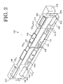
- FIG. 2 is a perspective view schematically showing a schematic construction of the elevated carriage conveying apparatus 100 of FIG. 1.
- the carriage conveying apparatus 100 is adapted to substantially linearly move push or movable carriages 110 from one work station ST to another to apply a specified (predetermined or predeterminable) processing at each work station ST.
- a stocking table 101 for stoking sorted wires W having specified lengths and terminals T connected with both ends thereof is provided for each work station ST, and a wire laying board B on which a plurality of connector holders H for holding connectors C are arranged is carried by each push carriage 110.
- a specified submodule (wiring harness) is to be formed by successively inserting the wires W into the corresponding connectors C at the respective work stations ST.
- the elevated carriage conveying apparatus 100 has a frame 102 preferably forming an entire outer configuration.
- the frame 102 is formed e.g. by assembling a plurality of angles or brackets substantially into a box extending along a forward path PH1 e.g. by welding.
- the forward path PH1 for moving the carriages 110 from one work station ST to another along rails 103 (see FIG. 3) preferably formed by substantially L-shaped angles or brackets.
- a return path PH2 is formed or substantially defined by rails 104.
- the return path PH2 is provided substantially immediately below the forward path PH1 for returning the push carriages 110 having reached a downstream end of the forward path PH1 to an upstream end or end portion of the forward path PH1.
- a pair of elevators or elevated or elevating conveyors 120, 140 are provided preferably at the substantially opposite sides of the paths PH1, PH2.
- the push carriages 110 are or can be conveyed or moved or elevated from one path PH1 (PH2) to the other path PH2 (PH1) by the elevated conveyors 120, 140, thereby constructing an endless conveyor as a whole.
- the rails 104 forming the return path PH2 are preferably inclined by setting a height H1 at the upstream end larger than a height H2 at the downstream end, so that the push carriages 110 can return from the upstream end to the downstream end by the action of gravity as described later.
- FIG. 3 is a perspective view of the push carriage 110 of the carriage conveying apparatus 100 of FIG. 1.
- the push carriage 110 includes a frame-shaped base 111 and a board frame 112 supported on the base 111.
- the base 111 is formed e.g. by welding pipes to have a substantially rectangular shape in plan view, and rollers 111a are mounted on its longer side surfaces (only one side is shown in FIG. 3).
- the base 111 is horizontally movable by rolling the rollers 111a on the rails 103 (or rails 104).
- a pair of elastic stoppers, preferably of rubber stoppers 111b are mounted on each of shorter side surfaces of the base 111.
- the board frame 112 is adapted to hold the wire laying board B shown in phantom line, and is assembled e.g. by welding angles or brackets to have the substantially same shape in plan view as the base 111.
- the board frame 112 and the base 111 are coupled by a pair of hinges 113 provided at one side thereof, so that the board frame 112 can be inclined downward toward an operator.
- pairs of mounting plates 114, 115 are so affixed or welded at the other side of the base 111 and the board frame 112 as to cantilever or project.
- the mounting plates 114 mounted on the base 111 and the mounting plates 115 mounted on the board frame 112 are provided in such positions where they can be substantially joined together.
- oblong holes 114a, 115a extending along an arc substantially centered on a center of rotation of the hinges 113.
- the board frame 112 and the base 111 can be assembled with the board frame 112 inclined by a specified angle by joining or fixedly connecting the mounting plates 114, 115 together or relative to each other preferably by means of unillustrated bolts inserted through the oblong holes 114a, 115a and nuts.
- an angle of inclination of the board frame 112 can be adjusted by changing a position of joining the mounting plates 114, 115 together along the extension of the oblong holes 114a, 115a.
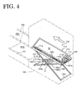
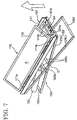
- FIGS. 4 to 7 are perspective views showing the schematic construction of the forwarding elevating or elevated conveyor 120 for transferring the carriages 110 from the downstream end of the return path PH2 to the upstream end of the forward path PH1.
- the elevated conveyor 120 includes a preferably substantially rectangular elevating table 121 which upon use or in operation is substantially vertically opposed to the push carriage 110, a parallel link 122 for linking the elevating table 121 and the push carriage 110, and an air cylinder 123 as an actuator for moving the elevating table 121 upward and downward or between the forward and return paths PH1, PH2.
- the elevating table 121 is preferably a frame member formed by assembling angles.
- the parallel link 122 is constructed as a pantograph system preferably by connecting intermediate positions of two pairs of link arms 122a, 122b assembled to have an X-shape in front view by a connecting shaft 122c extending in widthwise direction.
- the link arms 122a, 122b are coupled such that, for example, ends at the downstream end of the return path PH2 are fixed while ends at the upstream end of the forward path PH1 are substantially vertically slidable with an intersection ⁇ thereof as a center.
- the elevating table 121 can be smoothly moved upward and downward between an upper transfer position (see FIGS. 4 and 5) where the push carriage 110 is or can be transferred to the upstream end of the forward path PH1 and a lower transfer position (see FIG. 6) where the push carriage 110 is transferred from the downstream end of the return path PH2.
- the air cylinder 123 is preferably fixed while obliquely extending with respect to the frame 102, and a rod 123a thereof is coupled to a movable side of the parallel link 122.
- the elevating table 121 is raised by the air cylinder 123 extending the rod 123a while being lowered by the air cylinder 123 contracting the rod 123a.
- FIG. 8 is a perspective view partly cut away showing a portion of the elevating table 121 of the elevated conveyor shown in FIGS. 4 to 7.
- the longer sides of the elevating table 121 are formed by substantially symmetrically arranging a pair of L-shaped angles or brackets 121a to substantially face each other, and ends are formed by welding flat angles or brackets 121d to the lower surfaces of the angles 121a.
- the rails 121c formed by the L-shaped angles 121a are substantially in flush with the upper surfaces of the corresponding rails 103, 104 in the respective transfer positions, so that the push carriages 110 can be smoothly transferred (or received).
- the elevating table 121 can detachably lock the push carriage 110 transferred thereonto.
- the frame 102 is provided with a reverse movement preventing mechanism 125 in order to prevent the push carriage 110 transferred onto the elevating table 121 from the return path PH2 from moving in a reverse direction.
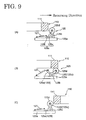
- FIG. 9 is a diagram showing an operation of the reverse movement preventing mechanism 125 shown in FIG. 8.
- the reverse movement preventing mechanism 125 is provided with a base 125a secured to the flat angle 102a of the frame 102 closer to the paths PH1, PH2, a pivot 125b rotatably supported on the base 125a along a horizontal direction substantially perpendicular to a returning direction, and a roller arm 125c pivotally supported via the pivot 125b, and a stopper roller 125d rotatably supported on the roller arm 125c.
- the roller arm 125c is substantially L-shaped and comprised of a bottom plate 125e placed at an angle different from 0° or 180°, preferably substantially normally placed on the base 125a and an arm portion 125f integrally standing on the bottom plate 125e.
- the arm portion 125f is provided at the downstream end of the bottom plate 125e with respect to a direction (returning direction) in which the push carriage 110 is guided onto the elevating table 121 from the return path PH2, and the stopper roller 125d is rotatably supported at the upper end thereof.
- a tension coil spring 127 as a biasing means having one end fixed to the base 125a is mounted at the upstream end of the bottom plate 125e with respect to the returning direction, and the roller arm 125c is biased in a direction to stand on the base 125a by the spring 127.
- the stopper roller 125d is located in a contact position where it is in contact with the downstream end face of the push carriage 110 (i.e. on the upstream end of the return path PH2 thereof) when the roller arm 125c is standing while being lowered to permit passage of the push carriage 110 when the roller arm 125c is rotated against a biasing force of the tension coil spring 127.
- the roller arm 125c is rotated clockwise to permit the push carriage 110 to be guided onto the elevating table 121 as shown in FIG. 9(B).
- the stopper roller 125d is engaged with the downstream end face of the push carriage 110 with respect to the returning direction as shown in FIG. 9(C), thereby preventing the push carriage 110 from moving in a direction opposite from the returning direction.
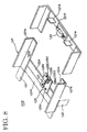
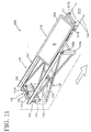
- FIGS. 10 and 11 are perspective views showing the schematic construction of the elevated conveyor 140
- FIG. 12 is a perspective view enlargedly showing a portion of the elevated conveyor 140 of FIG. 10
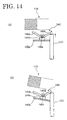
- FIGS. 13 and 14 are diagrams schematically showing the operation of the elevated conveyor 140 of FIG. 10.
- the returning elevated conveyor 140 includes, in principle, an elevating table 141, a parallel link 142, an air cylinder 143 and the like similar to the forwarding elevated conveyors 120.
- the elevating table 141 can be smoothly moved upward and downward between an upper transfer position (see FIG. 10) where the push carriage 110 is transferred from the downstream end of the forward path PH1 and a lower transfer position (see FIG. 11) where the push carriage 110 is transferred to the upstream end of the return path PH2.
- the push carriages 110 move over the forward path PH1, where preferably assembling or mounting operations (e.g.
- first elevating table 141 which transfers the push carriages 110 from (the downstream end of) the forward path PH1 to (the upstream end of) the return path PH2, where they can return back in a direction preferably substantially opposed to the direction of movement on the forward path PH1, so as to reach a second elevating table 121 arranged at the downstream end or side of the return path PH2, which transfers the push carriages 110 again back to (the upstream end of) the forward path PH1.
- the push carriages 110 can be circulated over the forward path PH1, the first elevating table 121, the return path PH2 and the second elevating table 121 in this order.
- contact plates 141d corresponding to the rubber stoppers 111b (see FIG. 11) of the push carriage 110 stand on a flat angle or bracket 141a located distant from the paths PH1, PH2. Further, a turning plate mechanism 145 for holding the base 111 of the push carriage 110 in cooperation with the contact plates 141d is provided between the contact plates 141d or on the flat angle 141a.
- the turning plate mechanism 145 includes a base 145a fixed to the flat angle 141a, bearings 145b standing on the base 145a, a pivot 145c rotatably or pivotably supported by the bearings 145b in a substantially horizontal direction perpendicular to the forward path PH1, and two plates 145d, 145e welded to the pivot 145c.
- the plates 145d, 145e radially extend while being spaced apart by a specified phase or angle different from 0° or 180° about the pivot 145c.
- One plate 145d is displaceable between a position where it is or can come in contact with an end of the base 145a by the action of gravity and a leading end portion thereof projects from the end of the base 145a and a position where it is spaced apart from the end of the base 145a.
- the other plate 145e extends obliquely to face an end face of the push carriage 110 when the one plate 145d is in contact with the base 145a while being retracted below the push carriage 110 when the one plate 145d is spaced apart from the end of the base 145a.
- the other plate 145e is pushed to rotate or pivot by the push carriage 110, thereby permitting the push carriage 110 to move in the forward direction until the rubber stoppers 111b (see FIG. 3) of the push carriage 110 come into contact with the corresponding contact plates 141d.
- the plates 145d, 145e are left in their free states in the base 111 of the push carriage 110, and the one plate 145d returns to the position to contact the base 145a again by the action of gravity, whereas the other plate 145e faces the rectangular pipe of the base 111 of the push carriage 110 as shown in FIG. 13(C) to prevent the push carriage 110 from moving in a reverse direction.
- a biasing means such as a spring may be provided to replace or sustain the action of gravity.
- a rod 152 stands on an angle or bracket 151 substantially horizontally extending between a pair of pillars 150 in the frame 102 in order to release locking of the push carriage 110 by the turning plate mechanism 145.
- the rod 152 is provided immediately below a free end of the one plate 145d in contact with the base 145a of the turning plate mechanism 145, and pushes the one plate 145d up as shown in FIG. 14(A) while the elevating table 141 is being lowered, thereby releasing locking of the push carriage 110 by the turning plate mechanism 145.
- bolts as contact bars 153 stand on the pair of pillars 150. These contact bars 153 come into contact with the downstream end of the elevating table 141 with respect to the forward direction so as to incline the lowered elevating table 141 as shown in FIG. 14(B). As a result, the push carriage 110 on the inclined elevating table 141 moves onto the rails 104 on the return path PH2 preferably by the action of gravity, and moves further to the forwarding elevated conveyor 120.
- a pair of pillars 150a are provided at a side opposite from the above pair of pillars 150, and contact bars 153a for height adjustment are provided on top of the pillars 150a to adjust the above inclination.
- the aforementioned elevated conveyors 120, 140 are provided with upper presence sensors S11, S21 for detecting the presence of the push carriage 110 in the upper transfer positions and lower presence sensors S12, S22 for detecting it in the lower transfer positions.
- elevated position sensors S14 see FIG. 5
- S24 for detecting in which of the upper and lower transfer positions the respective elevating tables 121, 141 are located depending on the driven states of the respective cylinders 123, 143 are provided.
- Identified by 128, 148 in FIG. 2 are safety covers for substantially covering the push carriages 110 in the upper transfer positions.
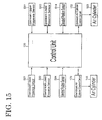
- FIG. 15 is a block diagram showing a control unit of the embodiment shown in FIG. 1.
- the carriage conveying apparatus 100 is provided with a control unit 170 for controlling operation timings of the respective elevated conveyors 120, 140.
- the control unit 170 is comprised of a microprocessor or like electronic device, and detection signals from the respective sensors S11, S21, S12, S22, S14, S24 are or can be inputted thereto. Further, the control unit 170 can control pressurized air supplying circuits 172, 173 for supplying a pressurized air to the air cylinders 123, 143.
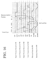
- FIG. 16 is a timing chart of the aforementioned embodiment.
- the elevating tables 121, 141 of the respective elevated conveyors 120, 140 are located in the upper transfer positions (see FIGS. 4 and 10), and a plurality of push carriages 110 are placed only on the rails 103 on the forward path PH1.
- one push carriage 110 is still on the elevating table 121 of the forwarding elevated conveyor 120 (see FIG. 4), whereas the returning elevated conveyor 140 is empty (see FIG. 10).
- the push carriage 110 at the downstream end of the forward path PH1 is first transferred onto the elevating table 141 of the returning elevated conveyor 140 by successively conveying the push carriages 110 standing in front of the respective work stations ST to the downstream side (see t1 of FIG. 16).
- the transferred push carriage 110 is (temporarily) locked or positioned on or fixed to the elevating table 141 by the turning plate mechanism 145 in the aforementioned procedure of FIGS. 13(A) to 13(C) and detected by the upper presence sensor S21 provided in the returning elevated conveyor 140.
- the control unit 170 waits without driving the returning elevated conveyor 140 until the elevating table 121 of the forwarding elevated conveyor 120 is displaced to the lower transfer position.
- the upper presence sensor S11 detects it (see t2 of FIG. 16). Then, the control unit 170 drives the air cylinder 123 to lower the elevating table 121. Thus, the elevating table 121 is lowered to the lower transfer position to wait on standby so as to receive the returning push carriage 110.
- the control unit 170 lowers the returning elevating table 141 (see t3 of FIG. 16) when the forwarding elevated conveyor 120 is lowered to the lower transfer position and the push carriage 110 is present in the upper transfer position of the returning elevated conveyor 140.
- the elevating table 141 is then inclined as described with reference to FIGS. 14(A) and 14(B).
- the push carriage 110 is sent out onto the rails 104 of the return path PH2 by the action of gravity as shown in FIG. 11 and further moves to the downstream end of the rails 104 (see t4 to t5 of FIG. 16).
- the carriages 110 may be moved on the return path PH2 by a driving means such as a motor, a chain sprocket combination or the like.
- the elevating table 141 is immediately returned to the upper transfer position (see t5 of FIG. 16).
- the returned push carriage 110 is guided onto the elevating table 121 of the forwarding elevated conveyor 120 waiting in the lower transfer position as shown in FIG. 6. Then, the push carriage 110 is (preferably temporarily) locked or fixedly positioned on the elevating table 121 (see FIG. 7) in the procedure described with reference to FIGS. 9(A) to 9(C), and detected by the lower presence sensor S12 (see t6 of FIG. 16).
- control unit 170 raises the elevating table 121 upon receipt of a detection signal of the lower presence sensor S12. Therefore, the elevated conveyor 120 returns to the state of FIG. 5 while carrying the push carriage 110 as shown in FIG. 7, with the result that the entire carriage conveying apparatus 100 returns to its initial state.
- the return path PH2 for circulating the push carriages 110 is formed immediately below the forward path PH1 for conveying the push carriages 110 from one work station to another, a circulating path fairly compact in plan view can be constructed. Accordingly, even in the case that the elevated carriage conveying apparatus 100 is connected with an unillustrated main conveyor in a branched manner to build a production line, a maximally compact layout of the carriage conveying apparatus 100 can be realized.
- the push carriages 110 on the return path PH2 can be automatically returned to the upstream side of the forward path PH1 without any consideration and without using any special driving source. Therefore, the operators can continuously do their works without being involved in the return of the push carriages 110.
Landscapes
- Engineering & Computer Science (AREA)
- Mechanical Engineering (AREA)
- Intermediate Stations On Conveyors (AREA)
- Automatic Assembly (AREA)
Abstract
To efficiently circulate push carriages 110 even in a limited space.
Forward and return paths PH1, PH2 for push carriages 110 are provided. The
return path PH2 is provided immediately below the forward path PH1. The push carriages
110 are made transferable from one to the other of the paths PH1, PH2 by a
pair of elevated conveyors 120, 140. In addition, the return path PH2 is inclined so
that the push carriages 110 return from an upstream side of the return path PH2 to a
downstream side thereof by the action of gravity.
Description
- The present invention relates to a carriage conveying apparatus and, particularly to an elevated carriage conveying apparatus for moving push carriages conveyed by operators from one work station to another.
- Generally, work boards, so-called "wire laying boards", are used to produce wiring harnesses. As a means to move the wire laying boards, carriages circulating on a conveyance path of an endless conveyor are utilized. Some kinds of wire laying boards are placed on push carriages, which are conveyed by hand and are circulated from one work station to another.
- A carriage conveying apparatus using the aforementioned push carriages needs to be installed in a relatively concentrated layout and the individual carriages need to be circulated in a very limited space. However, an inexpensive conveying apparatus which can circulate push carriages in a small space has not been developed up to the present. Thus, in the case that such a carriage conveying apparatus is used by being connected with a main conveyor for, e.g. assembling a plurality of sub-modules into a wiring harness, the connected conveying apparatus takes up a large space, disadvantageously enlarging a work line.
- In view of the above problem, an object of the present invention is to provide an inexpensive carriage conveying apparatus which can efficiently circulate carriages, in particular push carriages even in a limited space.
- This object is solved according to the invention by a carriage conveying apparatus according to
claim 1. Preferred embodiments are subject of the dependent claims. - According to the invention, there is provided a carriage conveying apparatus, comprising:
- a forward path for substantially linearly moving carriages from one work station to another, and
- a return path for moving the carriages from a downstream end of the forward path to an upstream end thereof,
- wherein the return path is provided immediately below the forward path, the two paths are connected by a pair of conveyors or elevators so that the carriages can be transferred from one to the other of the two paths.
-
- Since the return path for circulating the carriages is formed immediately below the forward path for conveying them from one work station to another in this invention, a circulating path compact in plan view can be constructed. Even in the case that this elevated carriage conveying apparatus is connected with a main conveyor in a branched manner to construct a production line, it can be installed in a maximally concentrated layout.
- According to a preferred embodiment of the invention, the return path is inclined such that the carriages return from an upstream side of the return path to a downstream side thereof at least partly by the action of gravity.
- Preferably, the carriages are conveyed from the upstream end of the forward path to the downstream end thereof by being pushed by the operators.
- According to a preferred embodiment, there is provided an elevated carriage conveying apparatus, comprising:
- a forward path for linearly moving push carriages manually conveyed by operators from one work station to another, and
- a return path for moving the carriages from a downstream end of the forward path to an upstream end thereof,
- the carriages being conveyed from the upstream end of the forward path to the downstream end thereof by being pushed by the operators,
- wherein the return path is provided immediately below the forward path, the two paths are connected by a pair of elevated conveyors so that the carriages can be transferred from one to the other of the two paths, and the return path is inclined such that the carriages return from an upstream side of the return path to a downstream side thereof by the action of gravity.
-
- Since the return path is preferably so inclined as to return the carriages by the action of gravity, the carriages on the return path can be automatically returned to the upstream side of the forward path without any consideration and without using any special driving source.
- Preferably, the pair of conveyors comprise:
- elevating tables elevated and lowered between upper transfer positions where the carriages can be transferred from and to the forward path and lower transfer positions where the carriages can be transferred from and to the return path and
- driving units for elevating and lowering the elevating tables between the upper and lower transfer positions.
-
- Further preferably, the carriage conveying further comprises one or more position detecting means for detecting elevated and/or lowered positions of the elevating tables in the corresponding transfer positions, and
a control unit for controlling operations of the driving units in accordance with signals from the position detecting means. - Most preferably, the control unit permits the elevating table provided at the upstream side of the return path to be lowered only when the elevating table provided at the downstream side of the return path is located in the lower transfer position.
- Particularly, the pair of elevated conveyors preferably comprise:
- elevating tables elevated and lowered between upper transfer positions where the carriages are transferred from and to the forward path and lower transfer positions where the carriages are transferred from and to the return path,
- position detecting means for detecting elevated and lowered positions of the elevating tables in the corresponding transfer positions,
- driving units for elevating and lowering the elevating tables between the upper and lower transfer positions, and
- a control unit for controlling operations of the driving units in accordance with signals from the position detecting means,
- wherein the control unit permits the elevating table provided at the upstream side of the return path to be lowered only when the elevating table provided at the downstream side of the return path is located in the lower transfer position.
-
- With such (elevated) conveyors, the carriages can be securely transferred from the downstream end of the return path to the elevating table even if they are conveyed from the upstream side to the downstream side of the return path by the action of gravity.
- Preferably, carriage detection sensors for detecting the presence of the carriage are provided in the upper and lower transfer positions of the respective elevated conveyors and connected with the control unit such that detection signals can be inputted to the control unit.
- In such a case, the control unit can execute a more precise control.
- Further preferably, each driving unit comprises a parallel link or pantograph system for supporting the elevating table such that the elevating table can be elevated and lowered, and preferably a single air cylinder for driving the parallel link.
- With such a driving unit, each elevating table can be elevated and lowered between the upper and lower transfer positions by the single air cylinder.
- Most preferably, the conveyors comprise temporary holding for temporarily or releasably holding or locking the carriage positioned thereon substantially during the transfer from one to the other of the two paths.
- These and other objects, features and advantages of the present invention will become apparent upon reading of the following detailed description of preferred embodiments and accompanying drawings in which:
- FIG. 1 is a schematic plan view of an elevated carriage conveying apparatus according to one embodiment of the invention,
- FIG. 2 is a perspective view schematically showing the schematic construction of the elevated carriage conveying apparatus of FIG. 1,
- FIG. 3 is a perspective view of a push carriage used in the elevated carriage conveying apparatus of FIG. 1,
- FIGS. 4 to 7 are perspective views showing the schematic construction of a forwarding elevated conveyor for transferring a received push carriage from the downstream end of a return path to the upstream end of a forward path,
- FIG. 8 is a perspective view partly cut away showing a portion of an elevating table of the elevated conveyor of FIG. 5,
- FIG. 9 is a diagram showing an operation of a reverse movement preventing mechanism shown in FIG. 8,
- FIGS. 10 and 11 are perspective views showing the schematic construction of a returning elevated conveyor,
- FIG. 12 is a perspective view enlargedly showing a portion of the elevated conveyor of FIG. 10,
- FIGS. 13 and 14 are diagrams schematically showing an operation of the elevated conveyor of FIG. 10,
- FIG. 15 is a block diagram showing a control unit of the embodiment of FIG. 1, and
- FIG. 16 is a timing chart of the aforementioned embodiment.
-
- Hereinafter, a preferred embodiment of the invention is described with reference to the accompanying drawings.
- FIG. 1 is a schematic plan view of a carriage conveying apparatus or mechanism or an elevated
carriage conveying apparatus 100 according to one preferred embodiment of the invention, and FIG. 2 is a perspective view schematically showing a schematic construction of the elevatedcarriage conveying apparatus 100 of FIG. 1. - First, with reference to FIG. 1, the
carriage conveying apparatus 100 is adapted to substantially linearly move push ormovable carriages 110 from one work station ST to another to apply a specified (predetermined or predeterminable) processing at each work station ST. In the shown example, a stocking table 101 for stoking sorted wires W having specified lengths and terminals T connected with both ends thereof is provided for each work station ST, and a wire laying board B on which a plurality of connector holders H for holding connectors C are arranged is carried by eachpush carriage 110. A specified submodule (wiring harness) is to be formed by successively inserting the wires W into the corresponding connectors C at the respective work stations ST. Even though the following description is given with respect to pushcarriages 110, it is to be understood that also any other kind of carriage or moving means being driven or having an internal driving means may be used instead or additionally. - Next, with reference to FIG. 2, the elevated
carriage conveying apparatus 100 according to the shown embodiment has aframe 102 preferably forming an entire outer configuration. Theframe 102 is formed e.g. by assembling a plurality of angles or brackets substantially into a box extending along a forward path PH1 e.g. by welding. On top of theframe 102 is formed the forward path PH1 for moving thecarriages 110 from one work station ST to another along rails 103 (see FIG. 3) preferably formed by substantially L-shaped angles or brackets. - In a bottom part of the
frame 102, a return path PH2 is formed or substantially defined byrails 104. The return path PH2 is provided substantially immediately below the forward path PH1 for returning thepush carriages 110 having reached a downstream end of the forward path PH1 to an upstream end or end portion of the forward path PH1. A pair of elevators or elevated or elevatingconveyors push carriages 110 are or can be conveyed or moved or elevated from one path PH1 (PH2) to the other path PH2 (PH1) by theelevated conveyors rails 104 forming the return path PH2 are preferably inclined by setting a height H1 at the upstream end larger than a height H2 at the downstream end, so that thepush carriages 110 can return from the upstream end to the downstream end by the action of gravity as described later. - Next, with reference to FIG. 3, the shown elevated
carriage conveying apparatus 100 is described in detail. FIG. 3 is a perspective view of thepush carriage 110 of thecarriage conveying apparatus 100 of FIG. 1. With reference to FIG. 3, thepush carriage 110 includes a frame-shapedbase 111 and aboard frame 112 supported on thebase 111. - The
base 111 is formed e.g. by welding pipes to have a substantially rectangular shape in plan view, androllers 111a are mounted on its longer side surfaces (only one side is shown in FIG. 3). Thebase 111 is horizontally movable by rolling therollers 111a on the rails 103 (or rails 104). A pair of elastic stoppers, preferably ofrubber stoppers 111b are mounted on each of shorter side surfaces of thebase 111. - The
board frame 112 is adapted to hold the wire laying board B shown in phantom line, and is assembled e.g. by welding angles or brackets to have the substantially same shape in plan view as thebase 111. Theboard frame 112 and the base 111 are coupled by a pair ofhinges 113 provided at one side thereof, so that theboard frame 112 can be inclined downward toward an operator. Further, pairs of mountingplates base 111 and theboard frame 112 as to cantilever or project. The mountingplates 114 mounted on thebase 111 and the mountingplates 115 mounted on theboard frame 112 are provided in such positions where they can be substantially joined together. In the respective mountingplates oblong holes hinges 113. Theboard frame 112 and the base 111 can be assembled with theboard frame 112 inclined by a specified angle by joining or fixedly connecting the mountingplates oblong holes board frame 112 can be adjusted by changing a position of joining the mountingplates oblong holes - FIGS. 4 to 7 are perspective views showing the schematic construction of the forwarding elevating or
elevated conveyor 120 for transferring thecarriages 110 from the downstream end of the return path PH2 to the upstream end of the forward path PH1. With reference to FIGS. 4 to 7, theelevated conveyor 120 includes a preferably substantially rectangular elevating table 121 which upon use or in operation is substantially vertically opposed to thepush carriage 110, aparallel link 122 for linking the elevating table 121 and thepush carriage 110, and anair cylinder 123 as an actuator for moving the elevating table 121 upward and downward or between the forward and return paths PH1, PH2. The elevating table 121 is preferably a frame member formed by assembling angles. Theparallel link 122 is constructed as a pantograph system preferably by connecting intermediate positions of two pairs oflink arms shaft 122c extending in widthwise direction. Thelink arms push carriage 110 is or can be transferred to the upstream end of the forward path PH1 and a lower transfer position (see FIG. 6) where thepush carriage 110 is transferred from the downstream end of the return path PH2. - The
air cylinder 123 is preferably fixed while obliquely extending with respect to theframe 102, and arod 123a thereof is coupled to a movable side of theparallel link 122. Thus, the elevating table 121 is raised by theair cylinder 123 extending therod 123a while being lowered by theair cylinder 123 contracting therod 123a. - FIG. 8 is a perspective view partly cut away showing a portion of the elevating table 121 of the elevated conveyor shown in FIGS. 4 to 7. As shown in FIG. 8, the longer sides of the elevating table 121 are formed by substantially symmetrically arranging a pair of L-shaped angles or
brackets 121a to substantially face each other, and ends are formed by welding flat angles orbrackets 121d to the lower surfaces of theangles 121a. - The
rails 121c formed by the L-shapedangles 121a are substantially in flush with the upper surfaces of thecorresponding rails push carriages 110 can be smoothly transferred (or received). -
Contact plates 121e corresponding to therubber stoppers 111b of thepush carriage 110 stand on theflat angle 121d located distant from the paths PH1, PH2, and amagnet 124 for attracting thebase 111 of thepush carriage 110 is provided therebetween. Thus, the elevating table 121 can detachably lock thepush carriage 110 transferred thereonto. In the shown example, theframe 102 is provided with a reversemovement preventing mechanism 125 in order to prevent thepush carriage 110 transferred onto the elevating table 121 from the return path PH2 from moving in a reverse direction. - FIG. 9 is a diagram showing an operation of the reverse
movement preventing mechanism 125 shown in FIG. 8. - As shown in FIGS. 8 and 9, the reverse
movement preventing mechanism 125 is provided with abase 125a secured to theflat angle 102a of theframe 102 closer to the paths PH1, PH2, apivot 125b rotatably supported on thebase 125a along a horizontal direction substantially perpendicular to a returning direction, and aroller arm 125c pivotally supported via thepivot 125b, and astopper roller 125d rotatably supported on theroller arm 125c. - As shown in FIG. 9, the
roller arm 125c is substantially L-shaped and comprised of abottom plate 125e placed at an angle different from 0° or 180°, preferably substantially normally placed on thebase 125a and anarm portion 125f integrally standing on thebottom plate 125e. Thearm portion 125f is provided at the downstream end of thebottom plate 125e with respect to a direction (returning direction) in which thepush carriage 110 is guided onto the elevating table 121 from the return path PH2, and thestopper roller 125d is rotatably supported at the upper end thereof. - A
tension coil spring 127 as a biasing means having one end fixed to thebase 125a is mounted at the upstream end of thebottom plate 125e with respect to the returning direction, and theroller arm 125c is biased in a direction to stand on thebase 125a by thespring 127. - The
stopper roller 125d is located in a contact position where it is in contact with the downstream end face of the push carriage 110 (i.e. on the upstream end of the return path PH2 thereof) when theroller arm 125c is standing while being lowered to permit passage of thepush carriage 110 when theroller arm 125c is rotated against a biasing force of thetension coil spring 127. - When the
push carriage 110 is moved in the returning direction to contact thestopper roller 125d as shown in FIG. 9(A), theroller arm 125c is rotated clockwise to permit thepush carriage 110 to be guided onto the elevating table 121 as shown in FIG. 9(B). After thepush carriage 110 is guided onto the elevating table 121, thestopper roller 125d is engaged with the downstream end face of thepush carriage 110 with respect to the returning direction as shown in FIG. 9(C), thereby preventing thepush carriage 110 from moving in a direction opposite from the returning direction. - Next, with reference to FIGS. 10 to 14, the returning or elevating elevated conveyor (or elevator) 140 is described in detail. FIGS. 10 and 11 are perspective views showing the schematic construction of the
elevated conveyor 140, FIG. 12 is a perspective view enlargedly showing a portion of theelevated conveyor 140 of FIG. 10, and FIGS. 13 and 14 are diagrams schematically showing the operation of theelevated conveyor 140 of FIG. 10. - The returning
elevated conveyor 140 includes, in principle, an elevating table 141, aparallel link 142, anair cylinder 143 and the like similar to the forwardingelevated conveyors 120. The elevating table 141 can be smoothly moved upward and downward between an upper transfer position (see FIG. 10) where thepush carriage 110 is transferred from the downstream end of the forward path PH1 and a lower transfer position (see FIG. 11) where thepush carriage 110 is transferred to the upstream end of the return path PH2. In other words, thepush carriages 110 move over the forward path PH1, where preferably assembling or mounting operations (e.g. wire-laying, bundling and/or connecting operations) are performed, then reach a first elevating table 141, which transfers thepush carriages 110 from (the downstream end of) the forward path PH1 to (the upstream end of) the return path PH2, where they can return back in a direction preferably substantially opposed to the direction of movement on the forward path PH1, so as to reach a second elevating table 121 arranged at the downstream end or side of the return path PH2, which transfers thepush carriages 110 again back to (the upstream end of) the forward path PH1. Accordingly, thepush carriages 110 can be circulated over the forward path PH1, the first elevating table 121, the return path PH2 and the second elevating table 121 in this order. Thus, it is advantageously possible to cycle thepush carriages 110 on the forward path PH1 by returning them, once they have reached the one side end or downstream end of the forward path PH1, to the beginning or upstream end of the forward path PH1 via the second elevating table 121, the return path PH2 (being preferably arranged substantially below the forward path PH1) and the second elevating table 121. - In the elevating table 141 shown in FIG. 10,
contact plates 141d corresponding to therubber stoppers 111b (see FIG. 11) of thepush carriage 110 stand on a flat angle orbracket 141a located distant from the paths PH1, PH2. Further, aturning plate mechanism 145 for holding thebase 111 of thepush carriage 110 in cooperation with thecontact plates 141d is provided between thecontact plates 141d or on theflat angle 141a. - As enlargedly shown in FIG. 12, the turning
plate mechanism 145 includes abase 145a fixed to theflat angle 141a,bearings 145b standing on thebase 145a, apivot 145c rotatably or pivotably supported by thebearings 145b in a substantially horizontal direction perpendicular to the forward path PH1, and twoplates pivot 145c. - The
plates pivot 145c. Oneplate 145d is displaceable between a position where it is or can come in contact with an end of thebase 145a by the action of gravity and a leading end portion thereof projects from the end of thebase 145a and a position where it is spaced apart from the end of thebase 145a. Theother plate 145e extends obliquely to face an end face of thepush carriage 110 when the oneplate 145d is in contact with thebase 145a while being retracted below thepush carriage 110 when the oneplate 145d is spaced apart from the end of thebase 145a. As a result, when thepush carriage 110 is guided from the forward path PH1 as shown in FIG. 13(A), theother plate 145e is pushed to rotate or pivot by thepush carriage 110, thereby permitting thepush carriage 110 to move in the forward direction until therubber stoppers 111b (see FIG. 3) of thepush carriage 110 come into contact with thecorresponding contact plates 141d. After reaching this state, theplates base 111 of thepush carriage 110, and the oneplate 145d returns to the position to contact thebase 145a again by the action of gravity, whereas theother plate 145e faces the rectangular pipe of thebase 111 of thepush carriage 110 as shown in FIG. 13(C) to prevent thepush carriage 110 from moving in a reverse direction. Alternatively or additionally, a biasing means such as a spring may be provided to replace or sustain the action of gravity. - With reference to FIG. 10, a
rod 152 stands on an angle orbracket 151 substantially horizontally extending between a pair ofpillars 150 in theframe 102 in order to release locking of thepush carriage 110 by the turningplate mechanism 145. Therod 152 is provided immediately below a free end of the oneplate 145d in contact with thebase 145a of theturning plate mechanism 145, and pushes the oneplate 145d up as shown in FIG. 14(A) while the elevating table 141 is being lowered, thereby releasing locking of thepush carriage 110 by the turningplate mechanism 145. - Further, as shown in FIG. 10, bolts as contact bars 153 stand on the pair of
pillars 150. These contact bars 153 come into contact with the downstream end of the elevating table 141 with respect to the forward direction so as to incline the lowered elevating table 141 as shown in FIG. 14(B). As a result, thepush carriage 110 on the inclined elevating table 141 moves onto therails 104 on the return path PH2 preferably by the action of gravity, and moves further to the forwardingelevated conveyor 120. In the shown example, a pair ofpillars 150a are provided at a side opposite from the above pair ofpillars 150, andcontact bars 153a for height adjustment are provided on top of thepillars 150a to adjust the above inclination. - With reference to FIG. 2, the aforementioned
elevated conveyors push carriage 110 in the upper transfer positions and lower presence sensors S12, S22 for detecting it in the lower transfer positions. Although not shown in detail, elevated position sensors S14 (see FIG. 5) and S24 (see FIG. 10) for detecting in which of the upper and lower transfer positions the respective elevating tables 121, 141 are located depending on the driven states of therespective cylinders push carriages 110 in the upper transfer positions. - FIG. 15 is a block diagram showing a control unit of the embodiment shown in FIG. 1.
- With reference to FIGS. 2 and 15, the
carriage conveying apparatus 100 is provided with acontrol unit 170 for controlling operation timings of the respectiveelevated conveyors control unit 170 is comprised of a microprocessor or like electronic device, and detection signals from the respective sensors S11, S21, S12, S22, S14, S24 are or can be inputted thereto. Further, thecontrol unit 170 can control pressurizedair supplying circuits air cylinders - Next, how the aforementioned embodiment operates is described.
- FIG. 16 is a timing chart of the aforementioned embodiment.
- With reference to FIGS. 1 and 16, in an initial state of the operation (hereinafter, "initial state"), the elevating tables 121, 141 of the respective
elevated conveyors push carriages 110 are placed only on therails 103 on the forward path PH1. In the initial state, onepush carriage 110 is still on the elevating table 121 of the forwarding elevated conveyor 120 (see FIG. 4), whereas the returningelevated conveyor 140 is empty (see FIG. 10). - Operators P start the operation in this state, and the
push carriage 110 at the downstream end of the forward path PH1 is first transferred onto the elevating table 141 of the returningelevated conveyor 140 by successively conveying thepush carriages 110 standing in front of the respective work stations ST to the downstream side (see t1 of FIG. 16). The transferredpush carriage 110 is (temporarily) locked or positioned on or fixed to the elevating table 141 by the turningplate mechanism 145 in the aforementioned procedure of FIGS. 13(A) to 13(C) and detected by the upper presence sensor S21 provided in the returningelevated conveyor 140. At this stage, thecontrol unit 170 waits without driving the returningelevated conveyor 140 until the elevating table 121 of the forwardingelevated conveyor 120 is displaced to the lower transfer position. - On the other hand, when the
push carriage 110 on the forwardingelevated conveyor 120 is sent out onto therails 103 of the forward path PH1, the upper presence sensor S11 detects it (see t2 of FIG. 16). Then, thecontrol unit 170 drives theair cylinder 123 to lower the elevating table 121. Thus, the elevating table 121 is lowered to the lower transfer position to wait on standby so as to receive the returningpush carriage 110. Thecontrol unit 170 lowers the returning elevating table 141 (see t3 of FIG. 16) when the forwardingelevated conveyor 120 is lowered to the lower transfer position and thepush carriage 110 is present in the upper transfer position of the returningelevated conveyor 140. - By this lowering operation, locking by the turning
plate mechanism 145 is first released and the elevating table 141 is then inclined as described with reference to FIGS. 14(A) and 14(B). By this inclination, thepush carriage 110 is sent out onto therails 104 of the return path PH2 by the action of gravity as shown in FIG. 11 and further moves to the downstream end of the rails 104 (see t4 to t5 of FIG. 16). Alternatively or additionally, thecarriages 110 may be moved on the return path PH2 by a driving means such as a motor, a chain sprocket combination or the like. After thepush carriage 110 is sent out and detected by the lower presence sensor S22, the elevating table 141 is immediately returned to the upper transfer position (see t5 of FIG. 16). - The returned
push carriage 110 is guided onto the elevating table 121 of the forwardingelevated conveyor 120 waiting in the lower transfer position as shown in FIG. 6. Then, thepush carriage 110 is (preferably temporarily) locked or fixedly positioned on the elevating table 121 (see FIG. 7) in the procedure described with reference to FIGS. 9(A) to 9(C), and detected by the lower presence sensor S12 (see t6 of FIG. 16). - Thereafter, the
control unit 170 raises the elevating table 121 upon receipt of a detection signal of the lower presence sensor S12. Therefore, theelevated conveyor 120 returns to the state of FIG. 5 while carrying thepush carriage 110 as shown in FIG. 7, with the result that the entirecarriage conveying apparatus 100 returns to its initial state. - Since the return path PH2 for circulating the
push carriages 110 is formed immediately below the forward path PH1 for conveying thepush carriages 110 from one work station to another, a circulating path fairly compact in plan view can be constructed. Accordingly, even in the case that the elevatedcarriage conveying apparatus 100 is connected with an unillustrated main conveyor in a branched manner to build a production line, a maximally compact layout of thecarriage conveying apparatus 100 can be realized. - Further, since the return path PH2 is so inclined as to return the
push carriages 110 by the action of gravity, thepush carriages 110 on the return path PH2 can be automatically returned to the upstream side of the forward path PH1 without any consideration and without using any special driving source. Therefore, the operators can continuously do their works without being involved in the return of thepush carriages 110. - The aforementioned embodiment is only an illustration of a preferred embodiment of the present invention, and the present invention is not limited thereto. Various design changes can be made without departing from the scope of the present invention.
- (1) Even though the preferred embodiment was described with respect to manually pushed carriages, the invention is also applicable to (externally and/or internally) driven carriages.
- As described above, quite a compact circulating path can be constructed, and the carriages can be automatically returned to the upstream side of the return path without using a special driving source. Thus, there is a significant effect of constructing an inexpensive elevating carriage conveying apparatus capable of efficiently circulating carriages even in a limited.
-
- 100
- elevated carriage conveying apparatus
- 110
- carriage
- 120
- forwarding elevated conveyor
- 121
- elevating table
- 122
- parallel link
- 123
- air cylinder
- 140
- returning elevated conveyor
- 141
- elevating table
- 142
- parallel link
- 143
- air cylinder
- 170
- control unit
- PH1
- forward path
- PH2
- return path
- S11, S21
- upper presence sensor
- S12, S22
- lower presence sensor
- S14, S24
- elevated position sensor
- ST
- work station
Claims (8)
- A carriage conveying apparatus (100), comprising:a forward path (PH1) for substantially linearly moving carriages (110) from one work station (ST) to another, anda return path (PH2) for moving the carriages (110) from a downstream end of the forward path (PH1) to an upstream end thereof,wherein the return path (PH2) is provided immediately below the forward path (PH1), the two paths (PH1, PH2) are connected by a pair of conveyors (120, 140) so that the carriages (110) can be transferred from one to the other of the two paths (PH1, PH2).
- A carriage conveying apparatus according to claim 1, wherein the return path (PH2) is inclined such that the carriages (110) return from an upstream side of the return path (PH2) to a downstream side thereof at least partly by the action of gravity.
- A carriage conveying apparatus according to one or more of the preceding claims, wherein the carriages (110) are conveyed from the upstream end of the forward path (PH1) to the downstream end thereof by being pushed by the operators (P).
- A carriage conveying apparatus according to one or more of the preceding claims, wherein the pair of conveyors comprise:elevating tables (121, 141) elevated and lowered between upper transfer positions where the carriages (110) can be transferred from and to the forward path (PH1) and lower transfer positions where the carriages (110) can be transferred from and to the return path (PH2), anddriving units (122, 123, 142, 143) for elevating and lowering the elevating tables (121, 141) between the upper and lower transfer positions.
- A carriage conveying apparatus according to claim 4, further comprising one or more position detecting means (S11; S21; S12; S22) for detecting elevated and/or lowered positions of the elevating tables (110) in the corresponding transfer positions, and
a control unit (170) for controlling operations of the driving units (122, 123, 142, 143) in accordance with signals from the position detecting means (S11; S21; S12; S22). - A carriage conveying apparatus according to claim 5, wherein the control unit (170) permits the elevating table (141) provided at the upstream side of the return path (PH2) to be lowered only when the elevating table (121) provided at the downstream side of the return path (PH2) is located in the lower transfer position.
- A carriage conveying apparatus according to claim 4, 5 or 6, wherein each driving unit (122, 123, 142, 143) comprises a parallel link (122, 142) for supporting the elevating table (121, 141) such that the elevating table (121, 141) can be elevated and lowered, and preferably a single air cylinder (123, 143) for driving the parallel link (122, 142).
- A carriage conveying apparatus according to one or more of the preceding claims, wherein the conveyors (120; 140) comprise temporary holding means (124; 125; 145) for temporarily holding the carriage (110) positioned thereon substantially during the transfer from one to the other of the two paths (PH1, PH2).
Applications Claiming Priority (2)
| Application Number | Priority Date | Filing Date | Title |
|---|---|---|---|
| JP34314099A JP2001157935A (en) | 1999-12-02 | 1999-12-02 | Elevating/lowering type truck carrying apparatus |
| JP34314099 | 1999-12-02 |
Publications (1)
| Publication Number | Publication Date |
|---|---|
| EP1106541A1 true EP1106541A1 (en) | 2001-06-13 |
Family
ID=18359229
Family Applications (1)
| Application Number | Title | Priority Date | Filing Date |
|---|---|---|---|
| EP00125399A Withdrawn EP1106541A1 (en) | 1999-12-02 | 2000-12-04 | Carriage conveying apparatus |
Country Status (3)
| Country | Link |
|---|---|
| US (1) | US6561338B2 (en) |
| EP (1) | EP1106541A1 (en) |
| JP (1) | JP2001157935A (en) |
Cited By (7)
| Publication number | Priority date | Publication date | Assignee | Title |
|---|---|---|---|---|
| GR20030100054A (en) * | 2003-02-06 | 2004-10-22 | Gravita Maquinas S L | Method and machine for the mechanical handling of loads over a production and assembly circuit |
| WO2004096676A1 (en) * | 2003-04-27 | 2004-11-11 | Mtu Aero Engines Gmbh | Device and method for displacing gas turbines, especially during maintenance thereof |
| EP1516834A1 (en) * | 2003-09-21 | 2005-03-23 | Inova Pharma Systems GmbH | Device for transporting nested containers |
| NL2007082C2 (en) * | 2011-07-11 | 2013-01-14 | Verbruggen Mechanisatie B V | DEVICE AND METHOD FOR MANUALLY CHECKING HARVESTED CROPS, IN PARTICULAR PREIECE. |
| CN104891123A (en) * | 2015-05-28 | 2015-09-09 | 上海千山远东制药机械有限公司 | Two-way feeding and discharging rail type automatic transfer car |
| WO2017213612A1 (en) * | 2016-06-08 | 2017-12-14 | Elopar Elektrik Ve Otomotiv Parcalari Sanayi Ve Ticaret Anonim Sirketi | Manually advanced wiring harness grouping machine with increased safety |
| US11685611B2 (en) * | 2021-04-16 | 2023-06-27 | Synerlink | System for loading and unloading plates into and out of a machine processing containers |
Families Citing this family (15)
| Publication number | Priority date | Publication date | Assignee | Title |
|---|---|---|---|---|
| CN100341754C (en) * | 2002-09-26 | 2007-10-10 | 金在镕 | Shoe making machine |
| TWI247590B (en) * | 2003-08-08 | 2006-01-21 | Liang Jiang Shoes Making Machi | Cyclic conveyance system for shoe processor |
| US7219832B2 (en) * | 2004-06-17 | 2007-05-22 | First Data Corporation | ATM machine and methods with currency conversion capabilities |
| JP4995670B2 (en) * | 2007-08-30 | 2012-08-08 | 株式会社ミマキエンジニアリング | Printing device |
| JP5196918B2 (en) * | 2007-08-30 | 2013-05-15 | 株式会社ミマキエンジニアリング | Manufacturing method of printing apparatus |
| JP2009056656A (en) * | 2007-08-30 | 2009-03-19 | Mimaki Engineering Co Ltd | Printing device |
| NL1034915C2 (en) * | 2008-01-15 | 2009-07-16 | Gege Machb B V | Device for processing harvested crops at the location of processing stations. |
| US20110073534A1 (en) * | 2009-09-28 | 2011-03-31 | Niels Linge | Sorting Installation and Method for Sorting Articles |
| ATE543759T1 (en) * | 2009-11-27 | 2012-02-15 | Psb Intralogistics Gmbh | PICKING DEVICE AND METHOD FOR PICKING |
| ITFI20120206A1 (en) * | 2012-10-11 | 2014-04-12 | Fosber Spa | "LINE FOR THE PROCESSING OF A CONTINUOUS AND RELATED METHOD OF NASTRIFORM MATERIAL" |
| CN104122844B (en) * | 2013-04-23 | 2017-05-03 | 纬创资通(昆山)有限公司 | Processing system and processing method |
| JP6393641B2 (en) * | 2015-03-23 | 2018-09-19 | 株式会社ユニバーサルエンターテインメント | Production line |
| JP6335822B2 (en) * | 2015-03-23 | 2018-05-30 | 株式会社ユニバーサルエンターテインメント | Production line |
| CN109436706A (en) * | 2018-11-29 | 2019-03-08 | 上海天永智能装备股份有限公司 | A kind of conveying sliding table suitable for cohesion device |
| EP4400456B1 (en) * | 2022-11-22 | 2026-03-25 | Contemporary Amperex Technology (Hong Kong) Limited | Conveying device and automated assembly line |
Citations (5)
| Publication number | Priority date | Publication date | Assignee | Title |
|---|---|---|---|---|
| US2028008A (en) * | 1931-08-19 | 1936-01-14 | Peyinghaus Walter | Apparatus for continuous machining of work-pieces and particularly in housings for axial bearings of rear vehicles |
| FR2444535A1 (en) * | 1978-12-21 | 1980-07-18 | Reymond Jean | Semi-gravitational system - for cycling trolley for continuous conveyor system for operating continuous processes such as moulding or coating operations |
| JPS5766833A (en) * | 1980-10-06 | 1982-04-23 | Hitachi Ltd | Mixed assembling production system |
| EP0387487A2 (en) * | 1989-03-11 | 1990-09-19 | PROTECH AUTOMATION GmbH | Assembling line |
| GB2336693A (en) * | 1998-04-20 | 1999-10-27 | Denso Corp | Assembly apparatus with parts supplies and tool changing |
Family Cites Families (7)
| Publication number | Priority date | Publication date | Assignee | Title |
|---|---|---|---|---|
| US4449625A (en) * | 1980-10-01 | 1984-05-22 | Hauni-Werke Korber & Co. Kg. | Apparatus for transporting trays for cigarettes or the like |
| JPS57205054A (en) * | 1981-06-12 | 1982-12-16 | Honda Motor Co Ltd | Transfer type machining system |
| CH660819A5 (en) * | 1983-08-22 | 1987-06-15 | Micafil Ag | DEVICE FOR THE AUTOMATIC MANUFACTURING OF ANCHORS FOR SMALL ELECTRIC MOTORS AND A METHOD FOR OPERATING THE SAME. |
| CA1234924A (en) * | 1984-01-21 | 1988-04-05 | Hideo Sakamoto | Printed circuit board load-unload system with bypass route |
| US4507841A (en) * | 1984-05-17 | 1985-04-02 | Vista Polymers Inc. | Removal and reinstallation of bottom entering agitator seals |
| GB2193180B (en) * | 1986-07-31 | 1990-02-14 | Ibm | A conveyor system including a buffer store |
| JPH0821798B2 (en) * | 1989-09-05 | 1996-03-04 | 富士機械製造株式会社 | Electronic component supply device |
-
1999
- 1999-12-02 JP JP34314099A patent/JP2001157935A/en not_active Abandoned
-
2000
- 2000-12-01 US US09/728,093 patent/US6561338B2/en not_active Expired - Fee Related
- 2000-12-04 EP EP00125399A patent/EP1106541A1/en not_active Withdrawn
Patent Citations (5)
| Publication number | Priority date | Publication date | Assignee | Title |
|---|---|---|---|---|
| US2028008A (en) * | 1931-08-19 | 1936-01-14 | Peyinghaus Walter | Apparatus for continuous machining of work-pieces and particularly in housings for axial bearings of rear vehicles |
| FR2444535A1 (en) * | 1978-12-21 | 1980-07-18 | Reymond Jean | Semi-gravitational system - for cycling trolley for continuous conveyor system for operating continuous processes such as moulding or coating operations |
| JPS5766833A (en) * | 1980-10-06 | 1982-04-23 | Hitachi Ltd | Mixed assembling production system |
| EP0387487A2 (en) * | 1989-03-11 | 1990-09-19 | PROTECH AUTOMATION GmbH | Assembling line |
| GB2336693A (en) * | 1998-04-20 | 1999-10-27 | Denso Corp | Assembly apparatus with parts supplies and tool changing |
Non-Patent Citations (1)
| Title |
|---|
| PATENT ABSTRACTS OF JAPAN vol. 006, no. 146 (M - 147) 5 August 1982 (1982-08-05) * |
Cited By (9)
| Publication number | Priority date | Publication date | Assignee | Title |
|---|---|---|---|---|
| GR20030100054A (en) * | 2003-02-06 | 2004-10-22 | Gravita Maquinas S L | Method and machine for the mechanical handling of loads over a production and assembly circuit |
| WO2004096676A1 (en) * | 2003-04-27 | 2004-11-11 | Mtu Aero Engines Gmbh | Device and method for displacing gas turbines, especially during maintenance thereof |
| EP1710177A1 (en) * | 2003-04-27 | 2006-10-11 | MTU Aero Engines GmbH | Device and method for displacing gas turbines, especially during maintenance thereof |
| US7628268B2 (en) | 2003-04-27 | 2009-12-08 | Mtu Aero Engines Gmbh | Device and method for displacing gas turbines, especially during maintenance thereof |
| EP1516834A1 (en) * | 2003-09-21 | 2005-03-23 | Inova Pharma Systems GmbH | Device for transporting nested containers |
| NL2007082C2 (en) * | 2011-07-11 | 2013-01-14 | Verbruggen Mechanisatie B V | DEVICE AND METHOD FOR MANUALLY CHECKING HARVESTED CROPS, IN PARTICULAR PREIECE. |
| CN104891123A (en) * | 2015-05-28 | 2015-09-09 | 上海千山远东制药机械有限公司 | Two-way feeding and discharging rail type automatic transfer car |
| WO2017213612A1 (en) * | 2016-06-08 | 2017-12-14 | Elopar Elektrik Ve Otomotiv Parcalari Sanayi Ve Ticaret Anonim Sirketi | Manually advanced wiring harness grouping machine with increased safety |
| US11685611B2 (en) * | 2021-04-16 | 2023-06-27 | Synerlink | System for loading and unloading plates into and out of a machine processing containers |
Also Published As
| Publication number | Publication date |
|---|---|
| US6561338B2 (en) | 2003-05-13 |
| US20010002645A1 (en) | 2001-06-07 |
| JP2001157935A (en) | 2001-06-12 |
Similar Documents
| Publication | Publication Date | Title |
|---|---|---|
| EP1106541A1 (en) | Carriage conveying apparatus | |
| US7137769B2 (en) | Workpiece feeding apparatus | |
| CN102046456B (en) | System and method for synchronously conveying underbody components for vehicle body | |
| US4494298A (en) | Automatic assembling apparatus | |
| GB2103562A (en) | Pallet loading apparatus | |
| JP4725003B2 (en) | Panel conveyor | |
| EP0594884B1 (en) | Work conveyor | |
| JP5240488B2 (en) | Article receiving apparatus and article processing equipment | |
| JPH07315550A (en) | Pallet carrying device | |
| JP2846591B2 (en) | Equipment for sorting conveyed goods | |
| JP3872840B2 (en) | Substrate positioning device | |
| EP1199570A3 (en) | Method and device for automatic adjustment of printed circuit board conveying means in a test machine | |
| JP2001347431A (en) | Workbench and production system using the same | |
| JPH0617787Y2 (en) | Substrate transfer device | |
| CN223891886U (en) | A flip gate device | |
| JP3062619B2 (en) | Rack supply method and apparatus | |
| JPH0228401A (en) | Article transport arrangement | |
| JP3621518B2 (en) | Equipment loading on pallet | |
| KR870000578B1 (en) | Transfer machine | |
| JPH0447585B2 (en) | ||
| JPH0656058A (en) | Building method for vehicle component | |
| JP2007130918A (en) | Machine plate sorting device | |
| JP2001001089A (en) | Discharge side device of transfer press | |
| JP2004099254A (en) | Transfer device | |
| JPS6238977Y2 (en) |
Legal Events
| Date | Code | Title | Description |
|---|---|---|---|
| PUAI | Public reference made under article 153(3) epc to a published international application that has entered the european phase |
Free format text: ORIGINAL CODE: 0009012 |
|
| 17P | Request for examination filed |
Effective date: 20001228 |
|
| AK | Designated contracting states |
Kind code of ref document: A1 Designated state(s): DE FR GB |
|
| AX | Request for extension of the european patent |
Free format text: AL;LT;LV;MK;RO;SI |
|
| AKX | Designation fees paid |
Free format text: DE FR GB |
|
| 17Q | First examination report despatched |
Effective date: 20030901 |
|
| STAA | Information on the status of an ep patent application or granted ep patent |
Free format text: STATUS: THE APPLICATION IS DEEMED TO BE WITHDRAWN |
|
| 18D | Application deemed to be withdrawn |
Effective date: 20040111 |