EP1708213B1 - Electrochemical device - Google Patents
Electrochemical device Download PDFInfo
- Publication number
- EP1708213B1 EP1708213B1 EP06006616A EP06006616A EP1708213B1 EP 1708213 B1 EP1708213 B1 EP 1708213B1 EP 06006616 A EP06006616 A EP 06006616A EP 06006616 A EP06006616 A EP 06006616A EP 1708213 B1 EP1708213 B1 EP 1708213B1
- Authority
- EP
- European Patent Office
- Prior art keywords
- separator
- active material
- multilayer body
- electrodes
- electric double
- Prior art date
- Legal status (The legal status is an assumption and is not a legal conclusion. Google has not performed a legal analysis and makes no representation as to the accuracy of the status listed.)
- Expired - Lifetime
Links
Images
Classifications
-
- H—ELECTRICITY
- H01—ELECTRIC ELEMENTS
- H01G—CAPACITORS; CAPACITORS, RECTIFIERS, DETECTORS, SWITCHING DEVICES, LIGHT-SENSITIVE OR TEMPERATURE-SENSITIVE DEVICES OF THE ELECTROLYTIC TYPE
- H01G9/00—Electrolytic capacitors, rectifiers, detectors, switching devices, light-sensitive or temperature-sensitive devices; Processes of their manufacture
- H01G9/004—Details
- H01G9/02—Diaphragms; Separators
-
- Y—GENERAL TAGGING OF NEW TECHNOLOGICAL DEVELOPMENTS; GENERAL TAGGING OF CROSS-SECTIONAL TECHNOLOGIES SPANNING OVER SEVERAL SECTIONS OF THE IPC; TECHNICAL SUBJECTS COVERED BY FORMER USPC CROSS-REFERENCE ART COLLECTIONS [XRACs] AND DIGESTS
- Y02—TECHNOLOGIES OR APPLICATIONS FOR MITIGATION OR ADAPTATION AGAINST CLIMATE CHANGE
- Y02E—REDUCTION OF GREENHOUSE GAS [GHG] EMISSIONS, RELATED TO ENERGY GENERATION, TRANSMISSION OR DISTRIBUTION
- Y02E60/00—Enabling technologies; Technologies with a potential or indirect contribution to GHG emissions mitigation
- Y02E60/13—Energy storage using capacitors
Definitions
- the present invention relates to an electrochemical device.
- An electric double layer capacitor comprises a multilayer body having a separator and a pair of electrodes disposed so as to hold the separator therebetween; an outer bag containing the multilayer body; and an electrolyte infiltrated in the multilayer body.
- Such capacitors are known e.g. from US 2003/180 622 , wherein the separator has a thickness from 30-83 ⁇ m and is made of a nonwoven fabric compound of e.g. mixtures of polyester fibers, fibrillated organic fibers and cellulose or microglass fibers, and having average fiber diameters of less than 1 ⁇ m.
- the separator is an insulating, porous material for securing ion circulation while preventing the electrodes from coming into contact with each other (see, for example, Japanese Patent Application Laid-Open No. H 10-256088 ).
- Electrochemical devices such as the above-mentioned electric double layer capacitor have been demanded to further reduce their thickness.
- Nonwoven fabrics have often been in use as the separator.
- the present invention provides an electrochemical device according to claim 1 comprising a multilayer body having a separator and a pair of electrodes disposed so as to hold the separator therebetween, and an electrolyte infiltrated in the multilayer body.
- the electrodes contain an active material particle.
- the separator is made of a nonwoven fabric having an average fiber diameter Df of 0.1 to 1.0 ⁇ m. T ⁇ 5 ⁇ m and T/Df ⁇ 20, where T is the thickness of the separator. Dp ⁇ T, where Dp is the average particle size of the active material particle.
- the nonwoven fabric has an average fiber diameter Df of 0.1 to 1.0 ⁇ m, a separator thinner than conventional ones can be provided even when T/Df > 20.
- the separator Since the thickness T ⁇ 5 ⁇ m, the separator has a sufficient strength.
- the electrodes are less likely to short-circuit even when active material particles dropped out of the electrodes enter pinholes inevitably formed in the separator made of the nonwoven fabric.
- the electrochemical device can be provided sufficiently thinner than conventional ones.
- the separator has a melting point of 160°C or higher, since this allows multilayer body to be vacuum-dried in a short time at a high temperature of about 150°C.
- the present invention provides an electrochemical device which is thinner, shorter in leakage current, and less likely to cause a short circuit between electrodes as compared with conventional devices.
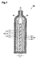
- Fig. 1 is a sectional view showing the electric double layer capacitor in accordance with an embodiment
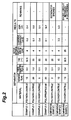
- Fig. 2 is a table showing characteristics of separators and active material particles and characteristics of resulting electric double layer capacitors in Examples 1 to 4 and Comparative Examples 1 to 3.
- an electric double layer capacitor As an example of the electrochemical device in accordance with an embodiment, an electric double layer capacitor will be explained.
- Fig. 1 is a sectional view showing the electric double layer capacitor 100 in accordance with this embodiment.
- the electric double layer capacitor (electrochemical device) 100 mainly comprises a multilayer body 20; an outer bag 50 containing the multilayer body 20; and a pair of leads 60, 62 connected to the multilayer body 20.
- each electrode 10 comprises an active material containing layer 14 provided on a collector 12.
- the active material containing layers 14, 14 are in contact with both sides of the separator 18, respectively.
- the leads 60, 62 are connected to respective end parts of the collectors 12, 12, whereas end parts of the leads 60, 62 extend to the outside of the outer bag 50.
- Each collector 12 is made of a metal foil such as aluminum foil, for example.
- Each active material containing layer 14 is a layer containing an active material particle, and is bonded to a surface of its corresponding collector 12.
- the active material containing layer 14 is formed by a mixture of an active material particle and a binder, for example.
- a binder for example.
- the active material particle acetylene black, graphite, black lead, and activated carbon, for example, may be used selectively or in mixtures of any ratios.
- the binder fluorine resins such as polyvinylidene fluoride (PVDF), for example, may be utilized.
- PVDF polyvinylidene fluoride
- Dp be the average particle size of the active material particle.
- the average particle size Dp can be measured by a laser diffraction/scattering method, for example, in a powder state.
- the number of grain boundaries of active material particles existing within a given length in an electron micrograph of a surface or cross section may be determined, for example, and the average particle size Dp can be calculated therefrom.
- the average particle size Dp is preferably on the order of 2 to 5 ⁇ m, for example.
- the separator 18 is formed from a nonwoven fabric.
- the nonwoven fabric is formed from fibers having an average fiber diameter Df and a thickness T.
- the average fiber diameter Df can be measured by an electron microscope.
- the material for fibers is preferably a resin, example of which in particular is a resin having a melting point of 160°C or higher such as polyacrylonitrile (PAN).
- PAN polyacrylonitrile
- the average fiber diameter Df is 0.1 to 1.0 ⁇ m, whereas T satisfies T ⁇ 5 ⁇ m and T/Df > 20. Also, Dp ⁇ T concerning the Dp of the active material particle and the thickness T of the separator 18.
- the multilayer body 20 is impregnated with an electrolyte.
- the electrolyte is mainly infiltrated in the separator 18 and the active material containing layers 14 in the electrodes 10.
- electrolytes employed in known electrochemical devices such as electric double layer capacitors (e.g., aqueous electrolyte solutions and nonaqueous electrolyte solutions using organic solvents) can be used.
- nonaqueous electrolytes typical examples of which include solutions of quaternary ammonium salts such as tetraethylammonium tetrafluoroborate in organic solvents such as propylene carbonate, diethylene carbonate, and acetonitrile.
- the outer bag 50 seals the multilayer body 20 and the electrolyte therewithin.
- the outer bag 50 is not limited in particular as long as it can prevent the electrolyte from leaking to the outside and moistures and the like from entering the electric double layer capacitor 100.
- a metal laminate film in which a metal foil 52 is coated with synthetic resin films 54 from both sides as shown in Fig. 1 can be used as the outer bag 50.
- An aluminum foil and a film such as polypropylene can be used as the metal foil and the synthetic resin film, for example.
- the leads 60, 62 are formed from a conductive material such as aluminum.
- the separator 18 can be realized thinner than conventional ones even when T/Df > 20.
- the separator can easily attain a thickness T of 20 ⁇ m or less, whereby an electrochemical device which is sufficiently thinner than conventional ones can be provided. Therefore, a higher energy density can be achieved.
- the separator having such a fiber diameter Df is favorable because of its high liquid retention, which can lower its internal resistance.
- the separator 18 Since T ⁇ 5 ⁇ m, the separator 18 has a sufficient strength and thus is hard to break during its manufacture, use, and the like.
- the separator 18 made of a nonwoven fabric inevitably has pinholes penetrating therethrough in its thickness direction, whereby active material particles desorbed from the active material containing layer 14 may enter the pinholes.
- the average particle size Dp of the active material particle satisfies Dp ⁇ T, a short circuit is less likely to occur between the electrodes 10, 10, i.e., between the active material containing layers 14, 14, even when the active material particles dropped out of the electrodes enter the pinholes of the separator 18.
- the electric double layer capacitor 100 is manufactured in the following manner.
- the multilayer body 20 having the leads 60, 62 connected thereto, the outer bag 50, and the electrolyte are prepared.
- the multilayer body 20 may be manufactured by a known method using materials satisfying the above-mentioned conditions.
- Each of the multilayer body 20 and the outer bag 50 is sufficiently dried. For example, it will be preferred if they are heated in the air and then heated in vacuum and so forth, so that their moistures are sufficiently reduced.
- the melting point of the nonwoven fabric is preferably 160°C or higher in the separator 18, since this allows multilayer body 20 to be vacuum-dried in a short time at a high temperature of about 150°C. The reduction in moisture can improve reliability in an electrochemical device using a nonaqueous electrolyte.
- the multilayer body 20 is accommodated in the outer bag 50, and the electrolyte is dropped into the multilayer body 20. Thereafter, the outer bag 50 is sealed, whereby the electric double layer capacitor is completed.
- the electric double layer capacitor 100 may be one in which a number of multilayer bodies 20 are laminated, for example.
- the average particle size of the activated carbon was 4 ⁇ m.
- the coating material was applied onto one face of an etching aluminum foil by doctor blading, the aluminum foil was dried in the air for 30 minutes at 100°C. The resulting product was extended by roll pressing. Then, the aluminum foil centered at the area formed with the coating film was punched out into a piece of 7.8 x 7.8 mm with a tab part, so as to yield an electrode for an electric double layer capacitor.
- a nonwoven fabric made of polyacrylonitrile having a thickness T of 13 ⁇ m and a fiber diameter Df of 0.4 ⁇ m was punched out into a piece of 8.2 x 8.2 mm, so as to yield a separator.
- the separator was held between two punched-out electrodes from both sides, so as to yield a multilayer body.
- a lead made of aluminum was welded to the tab part of the multilayer body by ultrasonic welding.
- the multilayer body having the lead attached thereto was held with an aluminum laminate film folded into two parts, and two sides thereof including a lead part were sealed under heat and pressure.
- the aluminum laminate bag containing the multilayer body was dried for 12 hours in a vacuum dryer at 160°C.
- a polycarbonate solution containing 1.0 mol/L of TEA-BF 4 added into the bag, the opening was sealed under reduced pressure, so as to yield the electric double layer capacitor of Example 1.
- Example 2 an electric double layer capacitor was obtained as in Example 1 except that a nonwoven fabric made of polyacrylonitrile having a thickness T of 20 ⁇ m and a fiber diameter D of 1 ⁇ m was used as the separator.
- Example 3 an electric double layer capacitor was obtained as in Example 1 except that a nonwoven fabric made of polyacrylonitrile having a thickness T of 5 ⁇ m and a fiber diameter D of 0.1 ⁇ m was used as the separator.
- Example 4 which is not an embodiment of the invention.
- Example 4 an electric double layer capacitor was obtained as in Example 1 except that a nonwoven fabric made of polypropylene having a thickness T of 20 ⁇ m and a fiber diameter D of 0.1 ⁇ m was used as the separator.
- Example 1 an electric double layer capacitor was obtained as in Example 1 except that a nonwoven fabric made of polyacrylonitrile having a thickness T of 2 ⁇ m and a fiber diameter D of 0.1 ⁇ m was used as the separator.
- Example 2 an electric double layer capacitor was obtained as in Example 1 except that a nonwoven fabric made of polyacrylonitrile having a thickness T of 10 ⁇ m and a fiber diameter D of 1.0 ⁇ m was used as the separator.
- Example 3 an electric double layer capacitor was obtained as in Example 1 except that the average particle size of the active material particle was 25 ⁇ m.
- Each of the electric double layer capacitors in accordance with the Examples and Comparative Examples was charged for 12 hours at a voltage of 2.7 V in an atmosphere at 85°C, and then was discharged in an atmosphere at 25°C. Subsequently, a part of the outer casing was perforated in a dry environment, and heat sealing was effected again under reduced pressure, so as to let out the gas stored therewithin. Then, a voltage of 2.1 V was applied for 1 hour in the atmosphere at 25°C, and the current flowing through the electric double layer capacitor after 1 hour therefrom was measured as a leakage current. Thereafter, discharging was performed at 25°C, and equivalent series resistance (ESR) was measured. Each value was an average of five electric double layer capacitors.
- Fig. 2 shows separator characteristics and electric double layer capacitors and results of measurement of electric double layer capacitors concerning the Examples and Comparative Examples.
- Example 4 which is not an embodiment of the invention exhibited a slightly higher equivalent series resistance of 19.7 F. This seems to be because of the fact that the separator was a nonwoven fabric made of polypropylene, which melted at the time of vacuum drying at 160°C and partly blocked openings of the nonwoven fabric.
Landscapes
- Engineering & Computer Science (AREA)
- Power Engineering (AREA)
- Microelectronics & Electronic Packaging (AREA)
- Electric Double-Layer Capacitors Or The Like (AREA)
- Cell Separators (AREA)
- Lubricants (AREA)
- Hybrid Cells (AREA)
Applications Claiming Priority (1)
| Application Number | Priority Date | Filing Date | Title |
|---|---|---|---|
| JP2005098524A JP2006278896A (ja) | 2005-03-30 | 2005-03-30 | 電気化学デバイス |
Publications (2)
| Publication Number | Publication Date |
|---|---|
| EP1708213A1 EP1708213A1 (en) | 2006-10-04 |
| EP1708213B1 true EP1708213B1 (en) | 2009-05-13 |
Family
ID=36581677
Family Applications (1)
| Application Number | Title | Priority Date | Filing Date |
|---|---|---|---|
| EP06006616A Expired - Lifetime EP1708213B1 (en) | 2005-03-30 | 2006-03-29 | Electrochemical device |
Country Status (7)
| Country | Link |
|---|---|
| US (1) | US7492573B2 (https=) |
| EP (1) | EP1708213B1 (https=) |
| JP (1) | JP2006278896A (https=) |
| CN (1) | CN1841600B (https=) |
| AT (1) | ATE431615T1 (https=) |
| DE (1) | DE602006006742D1 (https=) |
| TW (1) | TW200707487A (https=) |
Families Citing this family (3)
| Publication number | Priority date | Publication date | Assignee | Title |
|---|---|---|---|---|
| CN102414879B (zh) * | 2009-04-27 | 2015-04-15 | 加拿大巴斯姆有限公司 | 用于锂电化学电池的电极和电极材料 |
| KR102635455B1 (ko) | 2016-05-20 | 2024-02-13 | 교세라 에이브이엑스 컴포넌츠 코포레이션 | 고온용 울트라커패시터 |
| US11830672B2 (en) | 2016-11-23 | 2023-11-28 | KYOCERA AVX Components Corporation | Ultracapacitor for use in a solder reflow process |
Family Cites Families (21)
| Publication number | Priority date | Publication date | Assignee | Title |
|---|---|---|---|---|
| DE4233412C1 (de) | 1992-10-05 | 1994-02-17 | Freudenberg Carl Fa | Hydrophiliertes Separatorenmaterial aus Faservliesstoff für elektrochemische Energiespeicher und Verfahren zu seiner Herstellung |
| US5362581A (en) * | 1993-04-01 | 1994-11-08 | W. R. Grace & Co.-Conn. | Battery separator |
| JPH08171893A (ja) * | 1994-12-19 | 1996-07-02 | New Oji Paper Co Ltd | リチウム電池用セパレーター |
| JPH0927311A (ja) * | 1995-05-09 | 1997-01-28 | Mitsubishi Paper Mills Ltd | 電池セパレーター用不織布 |
| TW331669B (en) | 1995-08-05 | 1998-05-11 | Ever Ready Ltd | Additives and separators for electrochemical cells |
| JP3980113B2 (ja) | 1997-03-11 | 2007-09-26 | ニッポン高度紙工業株式会社 | 電気二重層コンデンサ |
| US6383427B2 (en) * | 1997-12-24 | 2002-05-07 | Asahi Glass Company, Ltd. | Process for producing an electric double layer capacitor electrode |
| US20030180662A1 (en) | 1998-05-25 | 2003-09-25 | Daicel Chemical Industries, Ltd. | Acid-sensitive compound and resin composition for photoresist |
| JP4324891B2 (ja) * | 1999-07-09 | 2009-09-02 | 日本エクスラン工業株式会社 | シート状材料 |
| WO2001093350A1 (en) * | 2000-05-29 | 2001-12-06 | Mitsubishi Paper Mills Limited | Separator for electrochemical device and method for producing the same, and electrochemical device |
| EP1442289A2 (en) | 2001-10-10 | 2004-08-04 | Lifescan, Inc. | Electrochemical cell |
| JP2003133181A (ja) * | 2001-10-25 | 2003-05-09 | Mitsubishi Paper Mills Ltd | キャパシタ用セパレーター |
| JP2004014592A (ja) | 2002-06-04 | 2004-01-15 | Mitsubishi Paper Mills Ltd | 電気二重層キャパシタ用セパレーター |
| JP2004149363A (ja) * | 2002-10-31 | 2004-05-27 | Honda Motor Co Ltd | 活性炭の製造方法 |
| JP2004349529A (ja) * | 2003-05-23 | 2004-12-09 | Nippon Zeon Co Ltd | 電気二重層キャパシタ用電極材料、及びその製造方法 |
| JP4425576B2 (ja) * | 2003-06-23 | 2010-03-03 | 日本バイリーン株式会社 | リチウム二次電池用セパレータ及びリチウム二次電池 |
| DE10336380B4 (de) | 2003-08-06 | 2005-08-25 | Carl Freudenberg Kg | Ultradünner, poröser und mechanisch stabiler Vliesstoff und dessen Verwendung |
| JP5131949B2 (ja) * | 2003-08-28 | 2013-01-30 | 株式会社Kri | キャパシタ |
| CN1553462A (zh) * | 2003-12-19 | 2004-12-08 | 南京双登科技发展研究院有限公司 | 超级电容器隔膜 |
| US7616428B2 (en) * | 2004-11-02 | 2009-11-10 | Japan Vilene Company, Ltd. | Separator for electric double layer capacitor and electric double layer capacitor containing same |
| JP4699102B2 (ja) | 2005-06-22 | 2011-06-08 | ルネサスエレクトロニクス株式会社 | 半導体装置 |
-
2005
- 2005-03-30 JP JP2005098524A patent/JP2006278896A/ja active Pending
-
2006
- 2006-03-28 US US11/390,072 patent/US7492573B2/en not_active Expired - Lifetime
- 2006-03-29 EP EP06006616A patent/EP1708213B1/en not_active Expired - Lifetime
- 2006-03-29 AT AT06006616T patent/ATE431615T1/de not_active IP Right Cessation
- 2006-03-29 DE DE602006006742T patent/DE602006006742D1/de not_active Expired - Lifetime
- 2006-03-30 TW TW095111302A patent/TW200707487A/zh unknown
- 2006-03-30 CN CN2006100718614A patent/CN1841600B/zh not_active Expired - Lifetime
Also Published As
| Publication number | Publication date |
|---|---|
| TWI292163B (https=) | 2008-01-01 |
| JP2006278896A (ja) | 2006-10-12 |
| CN1841600B (zh) | 2010-05-12 |
| ATE431615T1 (de) | 2009-05-15 |
| EP1708213A1 (en) | 2006-10-04 |
| CN1841600A (zh) | 2006-10-04 |
| TW200707487A (en) | 2007-02-16 |
| US20060221552A1 (en) | 2006-10-05 |
| US7492573B2 (en) | 2009-02-17 |
| DE602006006742D1 (de) | 2009-06-25 |
Similar Documents
| Publication | Publication Date | Title |
|---|---|---|
| KR100987260B1 (ko) | 전기화학소자 및 그 제조방법 | |
| KR101137975B1 (ko) | 전기 화학 소자의 제조방법 | |
| US8703323B2 (en) | Separator including porous coating layer and electrochemical device including the same | |
| JP5689800B2 (ja) | 多孔性コーティング層を備えたセパレータ及びこれを備えた電気化学素子 | |
| US6912116B2 (en) | Electrochemical device and process for producing same | |
| KR101229902B1 (ko) | 세퍼레이터용 다공질막, 전지용 세퍼레이터, 전지용 전극 및 그것들의 제조방법, 및 리튬 2차전지 | |
| EP1830374A1 (en) | Electric double layer capacitor | |
| US20050186479A1 (en) | Separator for electronic component and method for producing the same | |
| JPWO1999036981A1 (ja) | 電 池 | |
| KR102062123B1 (ko) | 전기 화학 디바이스 | |
| JP6684034B2 (ja) | 電気化学デバイス及び電気化学デバイスの製造方法 | |
| US11996583B2 (en) | Separator for electrochemical cell | |
| JP6684035B2 (ja) | 電気化学デバイス及び電気化学デバイスの製造方法 | |
| JP2001084985A (ja) | 二次電池 | |
| EP1708213B1 (en) | Electrochemical device | |
| JP2004319097A (ja) | 電気化学セル | |
| KR101696228B1 (ko) | 리튬 이온 커패시터 및 그 제조방법 | |
| KR102837722B1 (ko) | 컬링 현상 및 이온전도도를 개선시킨 전기화학소자용 코팅 분리막 및 그 제조 방법과, 그 전기화학소자 | |
| KR20180036858A (ko) | 전극 및 이를 이용한 이차전지와 전극의 제조방법 | |
| JP3800390B2 (ja) | 電気二重層コンデンサ | |
| JP5868158B2 (ja) | 蓄電デバイス | |
| JP2016164918A (ja) | 蓄電デバイスおよびその製造方法 | |
| JP2003045493A (ja) | 電気化学デバイスの製造方法 | |
| JP2006066696A (ja) | 電気化学素子 | |
| KR20000076154A (ko) | 전지 |
Legal Events
| Date | Code | Title | Description |
|---|---|---|---|
| PUAI | Public reference made under article 153(3) epc to a published international application that has entered the european phase |
Free format text: ORIGINAL CODE: 0009012 |
|
| AK | Designated contracting states |
Kind code of ref document: A1 Designated state(s): AT BE BG CH CY CZ DE DK EE ES FI FR GB GR HU IE IS IT LI LT LU LV MC NL PL PT RO SE SI SK TR |
|
| AX | Request for extension of the european patent |
Extension state: AL BA HR MK YU |
|
| 17P | Request for examination filed |
Effective date: 20070329 |
|
| 17Q | First examination report despatched |
Effective date: 20070425 |
|
| AKX | Designation fees paid |
Designated state(s): AT BE BG CH CY CZ DE DK EE ES FI FR GB GR HU IE IS IT LI LT LU LV MC NL PL PT RO SE SI SK TR |
|
| GRAP | Despatch of communication of intention to grant a patent |
Free format text: ORIGINAL CODE: EPIDOSNIGR1 |
|
| GRAS | Grant fee paid |
Free format text: ORIGINAL CODE: EPIDOSNIGR3 |
|
| GRAA | (expected) grant |
Free format text: ORIGINAL CODE: 0009210 |
|
| AK | Designated contracting states |
Kind code of ref document: B1 Designated state(s): AT BE BG CH CY CZ DE DK EE ES FI FR GB GR HU IE IS IT LI LT LU LV MC NL PL PT RO SE SI SK TR |
|
| REG | Reference to a national code |
Ref country code: GB Ref legal event code: FG4D |
|
| REG | Reference to a national code |
Ref country code: CH Ref legal event code: EP |
|
| REG | Reference to a national code |
Ref country code: IE Ref legal event code: FG4D |
|
| REF | Corresponds to: |
Ref document number: 602006006742 Country of ref document: DE Date of ref document: 20090625 Kind code of ref document: P |
|
| PG25 | Lapsed in a contracting state [announced via postgrant information from national office to epo] |
Ref country code: ES Free format text: LAPSE BECAUSE OF FAILURE TO SUBMIT A TRANSLATION OF THE DESCRIPTION OR TO PAY THE FEE WITHIN THE PRESCRIBED TIME-LIMIT Effective date: 20090824 Ref country code: FI Free format text: LAPSE BECAUSE OF FAILURE TO SUBMIT A TRANSLATION OF THE DESCRIPTION OR TO PAY THE FEE WITHIN THE PRESCRIBED TIME-LIMIT Effective date: 20090513 Ref country code: AT Free format text: LAPSE BECAUSE OF FAILURE TO SUBMIT A TRANSLATION OF THE DESCRIPTION OR TO PAY THE FEE WITHIN THE PRESCRIBED TIME-LIMIT Effective date: 20090513 Ref country code: PT Free format text: LAPSE BECAUSE OF FAILURE TO SUBMIT A TRANSLATION OF THE DESCRIPTION OR TO PAY THE FEE WITHIN THE PRESCRIBED TIME-LIMIT Effective date: 20090913 Ref country code: LT Free format text: LAPSE BECAUSE OF FAILURE TO SUBMIT A TRANSLATION OF THE DESCRIPTION OR TO PAY THE FEE WITHIN THE PRESCRIBED TIME-LIMIT Effective date: 20090513 |
|
| NLV1 | Nl: lapsed or annulled due to failure to fulfill the requirements of art. 29p and 29m of the patents act | ||
| PG25 | Lapsed in a contracting state [announced via postgrant information from national office to epo] |
Ref country code: SE Free format text: LAPSE BECAUSE OF FAILURE TO SUBMIT A TRANSLATION OF THE DESCRIPTION OR TO PAY THE FEE WITHIN THE PRESCRIBED TIME-LIMIT Effective date: 20090813 Ref country code: PL Free format text: LAPSE BECAUSE OF FAILURE TO SUBMIT A TRANSLATION OF THE DESCRIPTION OR TO PAY THE FEE WITHIN THE PRESCRIBED TIME-LIMIT Effective date: 20090513 Ref country code: NL Free format text: LAPSE BECAUSE OF FAILURE TO SUBMIT A TRANSLATION OF THE DESCRIPTION OR TO PAY THE FEE WITHIN THE PRESCRIBED TIME-LIMIT Effective date: 20090513 Ref country code: LV Free format text: LAPSE BECAUSE OF FAILURE TO SUBMIT A TRANSLATION OF THE DESCRIPTION OR TO PAY THE FEE WITHIN THE PRESCRIBED TIME-LIMIT Effective date: 20090513 Ref country code: IS Free format text: LAPSE BECAUSE OF FAILURE TO SUBMIT A TRANSLATION OF THE DESCRIPTION OR TO PAY THE FEE WITHIN THE PRESCRIBED TIME-LIMIT Effective date: 20090913 Ref country code: SI Free format text: LAPSE BECAUSE OF FAILURE TO SUBMIT A TRANSLATION OF THE DESCRIPTION OR TO PAY THE FEE WITHIN THE PRESCRIBED TIME-LIMIT Effective date: 20090513 |
|
| PG25 | Lapsed in a contracting state [announced via postgrant information from national office to epo] |
Ref country code: RO Free format text: LAPSE BECAUSE OF FAILURE TO SUBMIT A TRANSLATION OF THE DESCRIPTION OR TO PAY THE FEE WITHIN THE PRESCRIBED TIME-LIMIT Effective date: 20090513 Ref country code: EE Free format text: LAPSE BECAUSE OF FAILURE TO SUBMIT A TRANSLATION OF THE DESCRIPTION OR TO PAY THE FEE WITHIN THE PRESCRIBED TIME-LIMIT Effective date: 20090513 Ref country code: CZ Free format text: LAPSE BECAUSE OF FAILURE TO SUBMIT A TRANSLATION OF THE DESCRIPTION OR TO PAY THE FEE WITHIN THE PRESCRIBED TIME-LIMIT Effective date: 20090513 Ref country code: DK Free format text: LAPSE BECAUSE OF FAILURE TO SUBMIT A TRANSLATION OF THE DESCRIPTION OR TO PAY THE FEE WITHIN THE PRESCRIBED TIME-LIMIT Effective date: 20090513 |
|
| PG25 | Lapsed in a contracting state [announced via postgrant information from national office to epo] |
Ref country code: BE Free format text: LAPSE BECAUSE OF FAILURE TO SUBMIT A TRANSLATION OF THE DESCRIPTION OR TO PAY THE FEE WITHIN THE PRESCRIBED TIME-LIMIT Effective date: 20090513 Ref country code: SK Free format text: LAPSE BECAUSE OF FAILURE TO SUBMIT A TRANSLATION OF THE DESCRIPTION OR TO PAY THE FEE WITHIN THE PRESCRIBED TIME-LIMIT Effective date: 20090513 |
|
| PLBE | No opposition filed within time limit |
Free format text: ORIGINAL CODE: 0009261 |
|
| STAA | Information on the status of an ep patent application or granted ep patent |
Free format text: STATUS: NO OPPOSITION FILED WITHIN TIME LIMIT |
|
| PG25 | Lapsed in a contracting state [announced via postgrant information from national office to epo] |
Ref country code: BG Free format text: LAPSE BECAUSE OF FAILURE TO SUBMIT A TRANSLATION OF THE DESCRIPTION OR TO PAY THE FEE WITHIN THE PRESCRIBED TIME-LIMIT Effective date: 20090813 |
|
| 26N | No opposition filed |
Effective date: 20100216 |
|
| PG25 | Lapsed in a contracting state [announced via postgrant information from national office to epo] |
Ref country code: MC Free format text: LAPSE BECAUSE OF NON-PAYMENT OF DUE FEES Effective date: 20100331 Ref country code: GR Free format text: LAPSE BECAUSE OF FAILURE TO SUBMIT A TRANSLATION OF THE DESCRIPTION OR TO PAY THE FEE WITHIN THE PRESCRIBED TIME-LIMIT Effective date: 20090814 |
|
| REG | Reference to a national code |
Ref country code: CH Ref legal event code: PL |
|
| REG | Reference to a national code |
Ref country code: FR Ref legal event code: ST Effective date: 20101130 |
|
| PG25 | Lapsed in a contracting state [announced via postgrant information from national office to epo] |
Ref country code: IE Free format text: LAPSE BECAUSE OF NON-PAYMENT OF DUE FEES Effective date: 20100329 Ref country code: FR Free format text: LAPSE BECAUSE OF NON-PAYMENT OF DUE FEES Effective date: 20100331 |
|
| PG25 | Lapsed in a contracting state [announced via postgrant information from national office to epo] |
Ref country code: CH Free format text: LAPSE BECAUSE OF NON-PAYMENT OF DUE FEES Effective date: 20100331 Ref country code: LI Free format text: LAPSE BECAUSE OF NON-PAYMENT OF DUE FEES Effective date: 20100331 |
|
| PG25 | Lapsed in a contracting state [announced via postgrant information from national office to epo] |
Ref country code: IT Free format text: LAPSE BECAUSE OF FAILURE TO SUBMIT A TRANSLATION OF THE DESCRIPTION OR TO PAY THE FEE WITHIN THE PRESCRIBED TIME-LIMIT Effective date: 20090513 |
|
| PGFP | Annual fee paid to national office [announced via postgrant information from national office to epo] |
Ref country code: GB Payment date: 20110323 Year of fee payment: 6 |
|
| PG25 | Lapsed in a contracting state [announced via postgrant information from national office to epo] |
Ref country code: CY Free format text: LAPSE BECAUSE OF FAILURE TO SUBMIT A TRANSLATION OF THE DESCRIPTION OR TO PAY THE FEE WITHIN THE PRESCRIBED TIME-LIMIT Effective date: 20090513 |
|
| PG25 | Lapsed in a contracting state [announced via postgrant information from national office to epo] |
Ref country code: LU Free format text: LAPSE BECAUSE OF NON-PAYMENT OF DUE FEES Effective date: 20100329 Ref country code: HU Free format text: LAPSE BECAUSE OF FAILURE TO SUBMIT A TRANSLATION OF THE DESCRIPTION OR TO PAY THE FEE WITHIN THE PRESCRIBED TIME-LIMIT Effective date: 20091114 |
|
| PG25 | Lapsed in a contracting state [announced via postgrant information from national office to epo] |
Ref country code: TR Free format text: LAPSE BECAUSE OF FAILURE TO SUBMIT A TRANSLATION OF THE DESCRIPTION OR TO PAY THE FEE WITHIN THE PRESCRIBED TIME-LIMIT Effective date: 20090513 |
|
| GBPC | Gb: european patent ceased through non-payment of renewal fee |
Effective date: 20120329 |
|
| PG25 | Lapsed in a contracting state [announced via postgrant information from national office to epo] |
Ref country code: GB Free format text: LAPSE BECAUSE OF NON-PAYMENT OF DUE FEES Effective date: 20120329 |
|
| PGFP | Annual fee paid to national office [announced via postgrant information from national office to epo] |
Ref country code: DE Payment date: 20240130 Year of fee payment: 19 |
|
| REG | Reference to a national code |
Ref country code: DE Ref legal event code: R119 Ref document number: 602006006742 Country of ref document: DE |
|
| PG25 | Lapsed in a contracting state [announced via postgrant information from national office to epo] |
Ref country code: DE Free format text: LAPSE BECAUSE OF NON-PAYMENT OF DUE FEES Effective date: 20251001 |