EP1706318B1 - Achslager für eine banderolenrolle - Google Patents
Achslager für eine banderolenrolle Download PDFInfo
- Publication number
- EP1706318B1 EP1706318B1 EP05700323A EP05700323A EP1706318B1 EP 1706318 B1 EP1706318 B1 EP 1706318B1 EP 05700323 A EP05700323 A EP 05700323A EP 05700323 A EP05700323 A EP 05700323A EP 1706318 B1 EP1706318 B1 EP 1706318B1
- Authority
- EP
- European Patent Office
- Prior art keywords
- shaft
- flange
- axial bearing
- roll
- hub
- Prior art date
- Legal status (The legal status is an assumption and is not a legal conclusion. Google has not performed a legal analysis and makes no representation as to the accuracy of the status listed.)
- Expired - Lifetime
Links
- 230000006835 compression Effects 0.000 claims description 9
- 238000007906 compression Methods 0.000 claims description 9
- 230000000630 rising effect Effects 0.000 claims description 3
- 238000000926 separation method Methods 0.000 abstract 2
- 238000004519 manufacturing process Methods 0.000 description 3
- 230000001419 dependent effect Effects 0.000 description 2
- 239000011888 foil Substances 0.000 description 2
- 239000000463 material Substances 0.000 description 2
- 239000000123 paper Substances 0.000 description 2
- 238000003825 pressing Methods 0.000 description 2
- 238000003466 welding Methods 0.000 description 2
- 229910001369 Brass Inorganic materials 0.000 description 1
- 230000015572 biosynthetic process Effects 0.000 description 1
- 239000010951 brass Substances 0.000 description 1
- 239000002131 composite material Substances 0.000 description 1
- 238000005520 cutting process Methods 0.000 description 1
- 230000000994 depressogenic effect Effects 0.000 description 1
- 230000000694 effects Effects 0.000 description 1
- 238000010304 firing Methods 0.000 description 1
- 230000005484 gravity Effects 0.000 description 1
- 238000010438 heat treatment Methods 0.000 description 1
- 238000003780 insertion Methods 0.000 description 1
- 230000037431 insertion Effects 0.000 description 1
- 238000012423 maintenance Methods 0.000 description 1
- 230000007257 malfunction Effects 0.000 description 1
- 238000005096 rolling process Methods 0.000 description 1
- 125000006850 spacer group Chemical group 0.000 description 1
- 238000003860 storage Methods 0.000 description 1
- 230000001960 triggered effect Effects 0.000 description 1
Images



Classifications
-
- B—PERFORMING OPERATIONS; TRANSPORTING
- B65—CONVEYING; PACKING; STORING; HANDLING THIN OR FILAMENTARY MATERIAL
- B65B—MACHINES, APPARATUS OR DEVICES FOR, OR METHODS OF, PACKAGING ARTICLES OR MATERIALS; UNPACKING
- B65B13/00—Bundling articles
- B65B13/18—Details of, or auxiliary devices used in, bundling machines or bundling tools
- B65B13/185—Details of tools
-
- B—PERFORMING OPERATIONS; TRANSPORTING
- B65—CONVEYING; PACKING; STORING; HANDLING THIN OR FILAMENTARY MATERIAL
- B65H—HANDLING THIN OR FILAMENTARY MATERIAL, e.g. SHEETS, WEBS, CABLES
- B65H16/00—Unwinding, paying-out webs
- B65H16/02—Supporting web roll
- B65H16/04—Supporting web roll cantilever type
-
- B—PERFORMING OPERATIONS; TRANSPORTING
- B65—CONVEYING; PACKING; STORING; HANDLING THIN OR FILAMENTARY MATERIAL
- B65H—HANDLING THIN OR FILAMENTARY MATERIAL, e.g. SHEETS, WEBS, CABLES
- B65H2402/00—Constructional details of the handling apparatus
- B65H2402/50—Machine elements
- B65H2402/51—Joints, e.g. riveted or magnetic joints
-
- B—PERFORMING OPERATIONS; TRANSPORTING
- B65—CONVEYING; PACKING; STORING; HANDLING THIN OR FILAMENTARY MATERIAL
- B65H—HANDLING THIN OR FILAMENTARY MATERIAL, e.g. SHEETS, WEBS, CABLES
- B65H2701/00—Handled material; Storage means
- B65H2701/30—Handled filamentary material
- B65H2701/37—Tapes
-
- B—PERFORMING OPERATIONS; TRANSPORTING
- B65—CONVEYING; PACKING; STORING; HANDLING THIN OR FILAMENTARY MATERIAL
- B65H—HANDLING THIN OR FILAMENTARY MATERIAL, e.g. SHEETS, WEBS, CABLES
- B65H2701/00—Handled material; Storage means
- B65H2701/30—Handled filamentary material
- B65H2701/37—Tapes
- B65H2701/375—Strapping tapes
Definitions
- the invention relates to a journal bearing for a banding roll a banding machine with a rigidly attached to a machine frame or on a machine frame shaft and a likewise rigidly mounted rear cover plate, a freely rotatable hub on the shaft and arranged on the free end of the shaft flange a front cover disc.
- a band-shaped foil made of paper, plastic or a composite is guided in a stretch-limiting band guide as a loop around a packaged goods stack.
- This tape guide is designed as an open or closed sheet, depending on the rigidity of the bands, the dimensions and the use of the banded packaged goods stack.
- the packaged goods to be banded can be of any desired design, for example square, rectangular, round or trapezoidal with respect to the base area. At least one banderole is created, with several at the same time or one after the other.
- a fully automatic banding machine initially forms a stable or upheld loop in which the Packgutstapel is placed.
- the insertion of the stack of packaged goods can also be done before looping, sensor-controlled or triggered by a hand or foot switch, the clamped clamped at its free end is withdrawn until it fits snugly on the packaged. Then the clamped end is glued or welded to the tape and cut off.
- banding rolls deliver up to about 800 meters of paper and even 1300 meters of film, they must be replaced relatively frequently during continuous operation. In non-specialized companies, smaller banding rolls are used and possibly replaced depending on use. A roll change must therefore be as simple as possible with respect to the tensioning of the roll and the threading of the banderole.
- the customary band widths for bands are 15, 20, 30, 40, 50, 60, 75 and 100 mm.
- the diameter is compared to the bandwidth of large to very large, which is why to avoid lateral offsets on both sides are arranged covers, which do not rotate when rolling.
- Banding rolls have a roll core of cardboard, which is pushed onto the freely rotatable hub. Due to unavoidable manufacturing tolerances, the banding rolls are often inadequately deferred, wound on the roll, laterally offset banderoles grind on a cover plate, there is a braking effect, whereby the tape feed motor is overloaded. Annoying, on the production costs negative consequences temporary malfunctions should be remedied as a precaution.
- the invention has for its object to provide a journal bearing of the type mentioned, which allows a simpler role change and a trouble-free operation.
- the object is achieved according to the invention in that in the region of the flange, at least one pin projects in the radial direction from the shaft, which is not protruding into a guide slot of a detachably connected to the flange Bayonet bushing engages, which frontally open guide slot merges rising into an arcuate vertex and with a distance a from the end face of the bayonet sleeve and blindly ending in the direction of the end face of the bayonet, a tensioned between a shaft mount and the hub on the shaft compression spring is arranged, which presses the roll core with the band roll on the hub in the axial direction of the flange and together with this forms a quick release with centered Banderolenrolle, wherein the distance a corresponds to the distance of the roll core of the inserted, not yet pressed Banderolenrolle of the rear cover plate.
- the central element of the invention is the bayonet sleeve, which is longitudinally displaceable and simultaneously rotatable on the rigid shaft in accordance with the guide slots with bolts guided therein.
- the guide slots with the arcuate vertex allow the banderole roller to be pushed from the front to the rear cover disc and lateral dislocations directed with a continuous rotation of the flange in a first phase.
- the banding roller is removed because of the withdrawal of the flange and the action of a compression spring back from the rear cover plate and held in the final position approximately in the middle of the two cover plates.
- the axial position of the bayonet can be positioned and locked according to the bandwidth of the banding roll.
- the use of the same axlebox for different bandwidths is of considerable economic importance.
- the course of the guide slots is arbitrary, they are usually formed linearly rising, go into a circular arc and are in turn formed linear to the blind end. However, they can also increase degressively.
- the slope has an angle ⁇ of 30 to 60 °, preferably of about 45 °, and leads to the arc in the same angular range back to the blind end.
- the guide slot is returned to 0.3 to 0.7 a, preferably about 0.5 a.
- the banding roller is located centrally between the two cover discs, which is usually the goal.
- the distance a is matched to the specific conditions of the journal bearing. After turning the flange until it reaches the vertex with a feed a, the band roll must be taken along by the flange or the front cover disc until both cover slices fit snugly against the banderole roll. When turning further, the flange must be taken back, d. H. the crest must be exceeded. If the distance a is too great, this is not possible; if the distance a is too small, the bands are not directed.
- the roll core of the banding roll is not pushed directly onto the hub, but on protruding spring clips. This is essential because, on the one hand, the roll core does not have to be forcefully pressed onto the hub when the inside diameter is in the lower tolerance range, but on the other hand it does not loll or flutter when it is in the upper tolerance range.
- Fig. 1 shows a banding machine 10 with a height-adjustable chassis 12 on lockable wheels 14, also not essential to the invention components are shown, but not specifically described, because they are known in the art.
- a front cover plate 18 is rotatably mounted with a banding roller 20.
- a banderole 22 is unwound via a tape store 24, which comprises three stationary deflection rollers 26 and three deflection rollers 30 mounted on a pivotable lever 28. In the very rapid looping of the tape storage 24 is used as a reserve, the lever 28 is raised and lowers under the action of gravity again.
- the band 22 is pulled into a band channel 32, which is arranged in a machine housing 34 with a folding table 36.
- machine housing 34 further known per se machine elements are arranged, in particular a belt drive roller 38, a corresponding position of a lever 40, the band 22 to the capstan 38 pressing or this freewheel granting transport roller 42, with the band 22 exactly co-rotating encoder roller 44, a Hold-down plate 46, a welding and cutting unit 48, as well as a digital control 60 electrically connected to the drive of the capstan 38 and the encoder roller 44.
- the tape guide 50 in the region of stacked packaged goods 52 is open in the present case, by two plane symmetrically arranged Stitzhorne 54, which can be easily supplemented by a bottom open horizontal channel, for example according to the EP 0456604 A1 ,
- a switch is arranged, which can be formed as shown at the same time as a foot switch 56.
- a switch 56 activates the capstan 38, which pulls the band 22 at high speed through the band guide 50, or pushes. After the formation of a present above-free arc, the front end of the band 22 is clamped.
- the tape reel drive 38 rotates in the opposite direction and pulls the band around the inserted, stacked packaged goods 52 with adjustable voltage, which is referred to as return.
- a rigid shaft 62 extending perpendicularly to the machine frame 16 is arranged, which rests on a freewheeling hub 64.
- a rear cover plate 68 is attached to the machine frame 16.
- a banding roll 20 with a roll core 70 made of cardboard is partially pushed onto the hub 64.
- the front cover plate 18 is applied to the banding roll 20.
- the roll core 70 has the distance a from the rear cover plate 68.
- the front cover plate 18, which bears against the Banderolenrölle 20 is integrated into a flange 74.
- the flange 74 With its inner bore, the flange 74 is coaxial with a bayonet bushing 76, which in turn is pivotally mounted on the shaft 62.
- the flange 74 Radially outside the bayonet bushing 76, the flange 74 is formed as a handwheel with longitudinal ribs 112.
- the bayonet bush 76 which is sleeve-shaped in the present case, has two diagonally opposite guide slots 78, which end open on the inner end face 80 of the bayonet bushing 76. In these guide slots 78 each one perpendicular from the shaft 62 abkragender bolt 84 is guided.
- the guide slots 78 are shown in Fig. 9 in detail.
- the hub 64 which is not only free-running, but also freely displaceable in the axial direction of the shaft 62, is pressed against the transverse strut 16. At this point of pressure, the bolts 84 in the guide slots 78 have reached the highest point, the apex 118 ( Figure 9).
- the unit consisting of the flange 74, the bayonet 76 and the front cover plate 18 is now rotated in the direction of arrow 86, in turn clockwise, in the operating point shown in Fig. 6 and 7.
- the mentioned unit has again moved in the direction of the free end face 96 of the shaft 62.
- the banding roller 20 can spring back into the release shown in Fig. 7, it is now at a distance from the front cover plate 18 and the rear cover plate 68.
- a compression spring 88 shown in Fig. 8 shifts the hub 64 of the shaft support 90 and thus of the rear cover plate 68 away, the hub 64 can now rotate freely again together with the banding roll 20.
- Another compression spring 100 also removes the front cover plate 18 from the banderole roller 20.
- annular stop 92 is formed, which has the same diameter as the roller core 70.
- the ring stop 92 suitably has a lubricious inner surface. If the front shroud 18 should come too close to the banding roll 20, the ring stop 92 will drag on the roll core 70, thus keeping the banding material away from the front shroud 18. Therefore, only a small amount of friction loss occurs, which is only a fraction of the friction loss that would result when the banding material on the front cover plate 18 is dragging.
- the banding roll 20 has a width b of present 15 mm, the distance c of the banding roll 20 of the rear cover plate 68 is about 5 mm, the distance d of the banding roll 20 of the front cover plate 18 at about 4 mm.
- the banding roll 20 rests on the freely rotating hub 64. It is centered over spring clips 94.
- the shaft 62 is fixed on the machine frame 16 via the shaft support 90.
- the compression spring 88 which wraps around the shaft 62, keeps the hub 64 and shaft support 90 at an axial distance of a few millimeters. When a force is applied to the hub 64, it rests directly on the shaft support 90. When eliminating the back pressure, the original distance is restored manufactured, the hub 64 springs back.
- an axial bore 120 is recessed from the shaft 62.
- a pressure piece 98 is inserted, which rests a compression spring 100 in the bore 120.
- the spring force of the compression spring 100 is absorbed by an axially acting on the pressure piece 98 screw 102, which is bolted to the bayonet bushing 76.
- the bayonet bushing 76 is screwed to the flange 74, the end face 122 of the flange 74 has from the end face 124 of the bayonet sleeve 76 a corresponding to the bandwidth b of the band 22 adjustable distance t. This distance is fixed with a screw 106.
- a Si ring 108 and a fitting plate 110 is disposed on the shaft.
- a brass brush 114 is arranged as a grounding contact with a spacer 116.
- the guide slots 78 are shown in detail with the apex 118 of the Umlenkbogens.
- the distance a of the apex 118 is from the inner end face 80 of the bayonet bushing 76 and the pitch ⁇ of the guide slots 78 can be seen.
- the bolts 84 are in working position.
Landscapes
- Engineering & Computer Science (AREA)
- Mechanical Engineering (AREA)
- Basic Packing Technique (AREA)
- Support Of The Bearing (AREA)
- Mounting Of Bearings Or Others (AREA)
- Rolls And Other Rotary Bodies (AREA)
Description
- Die Erfindung bezieht sich auf ein Achslager für eine Banderolenrolle einer Banderoliermaschine mit einer starr an einem Maschinenrahmen oder an einem Maschinengestell befestigten Welle und einer ebenfalls starr befestigten hinteren Deckscheibe, einer auf der Welle frei drehbaren Nabe und einem auf der freien Stirnseite der Welle angeordneten Flansch mit einer vorderen Deckscheibe.
- In Banderoliermaschinen wird eine bandförmige Folie aus Papier, Kunststoff oder einem Verbund in einer die Ausdehnung begrenzenden Bandführung als Schlaufe um einen Packgutstapel geführt. Diese Bandführung ist als offener oder geschlossener Bogen ausgebildet, je nach der Steifigkeit der Banderolen, den Dimensionen und der Verwendung des banderolierten Packgutstapels.
- Grundsätzlich kann das zu banderolierende Packgut beliebig ausgebildet sein, beispielsweise bezüglich der Grundfläche quadratisch, rechteckig, rund oder trapezförmig. Es wird wenigstens eine Banderole angelegt, bei mehreren gleichzeitig oder nacheinander.
- Eine vollautomatisch arbeitende Banderoliermaschine bildet vorerst eine in sich stabile oder hochgehaltene Schlaufe, in welche der Packgutstapel gelegt wird. Das Einlegen des Packgutstapels kann auch vor der Schlaufenbildung erfolgen, sensorgesteuert oder mit einem Hand- oder Fussschalter ausgelöst, wird die an ihrem freien Ende festgeklemmte Banderole zurückgezogen, bis sie am Packgut satt anliegt. Dann wird das festgeklemmte Ende mit dem Band verklebt oder verschweisst und abgeschnitten.
- Das Grundprinzip des Banderolierens ist auf breiter Basis bekannt. In der
EP 0551244 A1 wird eine Banderoliermaschine beschrieben, welche eine Kaltschweissung umfasst. Diese Weiterentwicklung bürgt für einen sauberen Verschluss, macht weniger Wartung erforderlich, verhindert Ablagerungen von Folienbrand und das Ersetzen von Heizelementen. - Obwohl gegenwärtig Banderolenrollen bis etwa 800 m Papier und sogar 1300 m Folien liefern, müssen sie während einem kontinuierlichen Betrieb verhältnismässig häufig ausgewechselt werden. In nicht spezialisierten Betrieben werden kleinere Banderolenrollen verwendet und allenfalls je nach Verwendung ausgewechselt. Ein Rollenwechsel muss deshalb bezüglich des Aufspannens der Rolle und des Einfädelns der Banderole möglichst einfach sein.
- Die marktüblichen Bandbreiten für Banderolen liegen bei 15, 20, 30, 40, 50, 60, 75 und 100 mm. Der Durchmesser ist verglichen mit der Bandbreite gross bis sehr gross, weshalb zum Vermeiden von seitlichen Versetzungen beidseits Deckscheiben angeordnet sind, welche beim Abrollen nicht mitdrehen.
- Banderolenrollen haben einen Rollenkern aus Karton, welcher auf die frei drehbare Nabe aufgeschoben wird. Wegen unvermeidlichen Fertigungstoleranzen werden die Banderolenrollen nicht selten ungenügend aufgeschoben, auf der Rolle aufgewickelte, seitlich versetzte Banderolen schleifen an einer Deckscheibe, es entsteht ein Bremseffekt, wodurch der Bandeinzugsmotor überlastet wird. Lästige, auf die Produktionskosten negative Folgen zeitigende Betriebsstörungen sollten vorsorglich behoben werden.
- Der Erfindung liegt die Aufgabe zugrunde, ein Achslager der eingangs genannten Art zu schaffen, welches einen einfacheren Rollenwechsel und einen möglichst störungsfreien Betrieb erlaubt.
- Die Aufgabe wird erfindungsgemäss dadurch gelöst, dass im Bereich des Flanschs wenigstens ein Bolzen in radialer Richtung von der Welle abkragt, der nicht überstehend in einen Führungsschlitz einer mit dem Flansch lösbar verbundenen Bajonettbüchse eingreift, welcher stirnseitig offene Führungsschlitz ansteigend in einen bogenförmigen Scheitel übergeht und mit einem Abstand a von der Stirnfläche der Bajonetthülse wendet und blind endend in Richtung der Stirnfläche der Bajonettbüchse verläuft, eine zwischen einer Wellenhalterung und der Nabe auf der Welle gespannte Druckfeder angeordnet ist, welche den Rollenkern mit der Banderolenrolle über die Nabe in Axialrichtung an den Flansch drückt und mit diesem zusammen einen Schnellverschluss mit zentrierter Banderolenrolle bildet, wobei der Abstand a dem Abstand des Rollenkerns der eingelegten, noch nicht angedrückten Banderolenrolle von der hinteren Deckscheibe entspricht. Vorteilhafte und weiterbildende Ausführungsformen des Achslagers sind Gegenstand von abhängigen Patentansprüchen.
- Zentrales Element der Erfindung ist die Bajonettbüchse, welche auf der starren Welle nach Massgabe der Führungsschlitze mit darin geführten Bolzen längsverschiebbar und gleichzeitig drehbar ist. Die Führungsschlitze mit dem bogenförmigen Scheitel erlauben, dass mit einer kontinuierlichen Drehung des Flanschs in einer ersten Phase die Banderolenrolle von der vorderen an die hintere Deckscheibe gedrückt und seitliche Versetzungen gerichtet werden. Beim Weiterdrehen wird die Banderolenrolle wegen des Rückzugs des Flanschs und der Einwirkung einer Druckfeder wieder von der hinteren Deckscheibe entfernt und in der Endposition etwa mittig der beiden Deckscheiben gehalten wird. Das Drehen in der gleichen Richtung erlaubt, dass in der ersten Phase die beiden Deckscheiben die Banderolenrolle richten und in der zweiten Phase, nach dem Erreichen des Anschlags, die Rolle etwa mittig zwischen den Deckscheiben platziert ist. Die Endposition des Führungsschlitzes kann noch eine Verrastung aufweisen.
- Mit geeigneten Mitteln, insbesondere mit einer Schraube, kann die axiale Position der Bajonettbüchse entsprechend der Bandbreite der Banderolenrolle positioniert und arretiert werden. Die Verwendung des gleichen Achslagers für verschiedene Bandbreiten ist von erheblicher wirtschaftlicher Bedeutung.
- Der Verlauf der Führungsschlitze ist an sich beliebig, sie sind in der Regel linear ansteigend ausgebildet, gehen in einen kreisförmigen Bogen über und sind bis zum blinden Ende wiederum linear ausgebildet. Sie können jedoch auch degressiv ansteigen. Bevorzugt hat die Steigung einen Winkel α von 30 bis 60°, vorzugsweise von etwa 45°, und führt nach dem Bogen im gleichen Winkelbereich zurück zum blinden Ende. Bezüglich des Abstands dieses blinden Endes zur Scheitelfläche der Bajonetthülse wird der Führungsschlitz auf 0,3 bis 0,7 a zurückgeführt, vorzugsweise etwa 0,5 a. Beim letztgenannten Wert 0,5 a liegt die Banderolenrolle mittig zwischen den beiden Deckscheiben, was in der Regel angestrebt wird.
- Der Abstand a ist auf die speziellen Verhältnisse des Achslagers abgestimmt. Nach dem Drehen des Flanschs bis zum Erreichen des Scheitels mit einem Vorschub a muss die Banderolenrolle vom Flansch bzw. der vorderen Deckscheibe mitgenommen werden, bis beide Deckscheiben satt an der Banderolenrolle anliegen. Beim Weiterdrehen muss der Flansch zurückgenommen werden, d. h. der Scheitel überschritten sein. Bei zu grossem Abstand a ist dies nicht möglich, bei zu kleinem Abstand a werden die Banderolen nicht gerichtet.
- Nach einer besonders vorteilhaften Ausführungsform der Erfindung wird der Rollenkern der Banderolenrolle nicht direkt auf die Nabe aufgeschoben, sondern auf überstehende Federnklammern. Dies ist von wesentlicher Bedeutung, weil so der Rollenkern einerseits nicht mit Gewalt auf die Nabe gedrückt werden muss, wenn der Innendurchmesser im unteren Toleranzbereich liegt, aber andererseits auch nicht lottert bzw. flattert, wenn er im oberen Toleranzbereich liegt.
- Mit der vorliegenden Erfindung wird also nicht nur das Aufspannen von Banderolenrollen erleichtert und betriebssicherer, sondern auch unempfindlich gegen Fertigungstoleranzen für den Innendurchmesser des Rollenkerns gemacht. Das automatische Richten der Banderole auf der Banderolenrolle und das automatische Positionieren des Rollenkerns in der Mitte der Deckscheiben durch Rückfedern der entspannten Nabe beim vollständigen Drehen des Flanschs führt automatisch zur besten Lösung.
- Die Erfindung wird anhand von in der Zeichnung dargestellten Ausführungsbeispielen, welche auch Gegenstand von abhängigen Patentansprüchen sind, näher erläutert. Es zeigen schematisch:
- Fig. 1 eine Ansicht einer Banderoliermaschine mit einer Banderolenrolle,
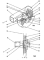
- Fig. 2 eine teilweise aufgebrochene Ansicht eines Achslagers einer aufgesteckten Banderolenrolle,
- Fig. 3 eine Seitenansicht von Fig. 2,
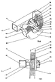
- Fig. 4 die Banderolenrolle gemäss Fig. 2 mit angelegter hinterer und vorderer Deckscheibe,
- Fig. 5 eine Seitenansicht gemäss Fig. 4,
- Fig. 6 die Banderolenrolle gemäss Fig. 2 in Endposition,
- Fig. 7 eine Seitenansicht von Fig. 6,
- Fig. 8 einen Axialschnitt durch eine Banderolenrolle in der Position von Fig. 7 und
- Fig. 9 die Führungsschlitze der Bajonetthülse in abgewickelter Darstellung.
- Fig. 1 zeigt eine Banderoliermaschine 10 mit einem höhenverstellbaren Fahrgestell 12 auf arretierbaren Rädern 14, auch nicht erfindungswesentliche Bestandteile sind gezeigt, jedoch nicht speziell beschrieben, weil sie dem Fachmann bekannt sind. An einer Querstrebe 16 des Fahrgestells 12 ist eine vordere Deckscheibe 18 mit einer Banderolenrolle 20 drehbar gelagert. Eine Banderole 22 wird über einen Bandspeicher 24 abgewickelt, welcher drei ortsfeste Umlenkrollen 26 und drei auf einem schwenkbaren Hebel 28 gelagerte Umlenkrollen 30 umfasst. Bei der sehr schnell erfolgenden Schlaufenbildung dient der Bandspeicher 24 als Reserve, der Hebel 28 wird angehoben und senkt sich unter Einwirkung der Schwerkraft wieder.
- Nach dem Bandspeicher 24 wird die Banderole 22 in einen Bandkanal 32 gezogen, welcher in einem Maschinengehäuse 34 mit einem Klapptischblech 36 angeordnet ist. In diesem Maschinengehäuse 34 sind weitere an sich bekannte Maschinenelemente angeordnet, insbesondere eine Bandantriebsrolle 38, eine bei entsprechender Stellung eines Hebels 40 die Banderole 22 an die Bandantriebsrolle 38 pressende oder dieser Freilauf gewährende Transportrolle 42, eine mit der Banderole 22 exakt mitlaufende Drehgeberrolle 44, eine Niederhalteplatte 46, eine Schweiss- und Schneideinheit 48, sowie eine mit dem Antrieb der Bandantriebsrolle 38 und der Drehgeberrolle 44 elektrisch verbundene Digitalsteuerung 60.
- Die Bandführung 50 im Bereich von gestapelten Packgut 52 erfolgt vorliegend offen, durch zwei plansymmetrisch angeordnete Stützhorne 54, welche ohne weiteres durch einen unten offenen Horizontalkanal ergänzt werden können, beispielsweise gemäss der
EP 0456604 A1 . - Unter einem Klappendeckel 58 ist ein Schalter angeordnet, welcher wie gezeigt gleichzeitig auch als Fussschalter 56 ausgebildet sein kann.
- Die Betätigung eines Schalters 56 aktiviert die Bandantriebsrolle 38, welche die Banderole 22 mit grosser Geschwindigkeit durch die Bandführung 50 zieht, bzw. stösst. Nach der Bildung eines vorliegend oben freien Bogens wird das stirnseitige Ende der Banderole 22 festgeklemmt. Der Bandrollenantrieb 38 dreht in die entgegengesetzte Richtung und zieht die Banderole um das eingelegte, gestapelte Packgut 52 mit einstellbarer Spannung an, was als Rücklauf bezeichnet wird.
- Gemäss Fig. 2 und 3 ist in einer Wellenhalterung 90 eines Achslagers 11 eine senkrecht zum Maschinenrahmen 16 verlaufende starre Welle 62 angeordnet, welcher eine freilaufende Nabe 64 aufsitzt. Über einen U-förmigen Lagerbock 66 ist eine hintere Deckscheibe 68 am Maschinenrahmen 16 befestigt.
- Wie insbesondere aus Fig. 3 ersichtlich ist eine Banderolenrolle 20 mit einem Rollenkern 70 aus Karton teilweise auf die Nabe 64 aufgestossen. Die vordere Deckscheibe 18 ist an die Banderolenrolle 20 angelegt. Der Rollenkern 70 hat von der hinteren Deckscheibe 68 den Abstand a.
- Die vordere Deckscheibe 18, welche an der Banderolenrölle 20 anliegt ist in einen Flansch 74 integriert. Mit seiner inneren Bohrung liegt der Flansch 74 koaxial auf einer Bajonettbüchse 76, welche ihrerseits schwenkbar auf der Welle 62 gelagert ist. Radial ausserhalb der Bajonettbüchse 76 ist der Flansch 74 als Handrad mit Längsrippen 112 ausgebildet. Die Bajonettbüchse 76, welche vorliegend hülsenförmig ausgebildet ist, weist zwei diagonal gegenüberliegende Führungsschlitze 78 auf, welche auf der inneren Stirnseite 80 der Bajonettbüchse 76 offen enden. In diesen Führungsschlitzen 78 ist je ein senkrecht von der Welle 62 abkragender Bolzen 84 geführt. Die Führungsschlitze 78 sind in Fig. 9 im Detail dargestellt.
- Von diesem Startpunkt auf der inneren Stirnseite 80 der Bajonettbüchse 76 aus wird eine Einheit, bestehend aus dem Flansch 74, der Bajonettbüchse 76 und der vorderen Deckscheibe 18, mit leichtem Druck in Axialrichtung der Welle 62 in Richtung des Pfeils 82 - also im Uhrzeigersinn - gedreht, bis der in Fig. 4 und 5 gezeigte Presspunkt erreicht ist. Die Banderolenrolle 20 einer Breite b wird bis zum Anschlag des Rollenkerns 64 an der Stufe 72 der Nabe 64 und der nun oberflächenbündigen hinteren Deckscheibe 68 weitergeschoben. An diesem Presspunkt werden auch seitlich versetzte Banderolen 22 eine Breite b der Banderolenrolle 20 gerichtet. Die Stufe 72 der zurückgedrängten Nabe 64 und die hintere Deckscheibe 68 sind oberflächenbündig. Die Nabe 64, welche nicht nur freilaufend, sondern auch in Axialrichtung der Welle 62 frei verschiebbar ist, wird gegen die Querstrebe 16 gedrückt. In diesem Presspunkt haben die Bolzen 84 in den Führungsschlitzen 78 den höchsten Punkt, den Scheitel 118, erreicht (Fig. 9).
- Die Einheit bestehend aus dem Flansch 74, der Bajonettbüchse 76 und der vorderen Deckscheibe 18 wird nun in Richtung des Pfeils 86, wiederum im Uhrzeigersinn, in den in Fig. 6 und 7 dargestellten Arbeitspunkt gedreht. Entsprechend dem Führungsschlitz 78 mit dem geführten Bolzen 84 hat sich die erwähnte Einheit wieder in Richtung der freien Stirnseite 96 der Welle 62 verschoben. Die Banderolenrolle 20 kann in die in Fig. 7 gezeigte Freistellung zurückfedern, sie liegt nun in Abstand zur vorderen Deckscheibe 18 und zur hinteren Deckscheibe 68. Eine in Fig. 8 gezeigte Druckfeder 88 verschiebt die Nabe 64 von der Wellenhalterung 90 und damit auch von der hinteren Deckscheibe 68 weg, die Nabe 64 kann nun wieder zusammen mit der Banderolenrolle 20 frei drehen. Eine weitere Druckfeder 100 entfernt auch die vordere Deckscheibe 18 von der Banderolenrolle 20. Innenseitig am Flansch 74 ist ein Ringanschlag 92 ausgebildet, welcher den gleichen Durchmesser wie der Rollenkern 70 hat. Der Ringanschlag 92 hat zweckmässig eine gleitfähige Innenfläche. Falls die vordere Deckscheibe 18 der Banderolenrolle 20 zu nahe kommen sollte, schleift der Ringanschlag 92 auf dem Rollenkern 70 und hält so das Banderolenmaterial von der vorderen Deckscheibe 18 fern. Daher entsteht lediglich ein kleiner reibungsbedingter Verlust, welcher nur einen Bruchteil des Reibungsverlustes ausmacht, der entstehen würde, wenn das Banderolenmaterial auf der vorderen Deckscheibe 18 schleift.
- In Fig. 8 ist die End- bzw. Arbeitsstellung des Achslagers 11 gemäss Fig. 6 und im Detail gezeigt. Die Banderolenrolle 20 hat eine Breite b von vorliegend 15 mm, der Abstand c der Banderolenrolle 20 von der hinteren Deckscheibe 68 liegt bei etwa 5 mm, der Abstand d der Banderolenrolle 20 von der vorderen Deckscheibe 18 bei etwa 4 mm. Die Banderolenrolle 20 liegt auf der frei drehenden Nabe 64 auf. Sie ist über Federklammern 94 zentriert. Die Welle 62 ist über die Wellenhalterung 90 auf dem Maschinenrahmen 16 fixiert.
- Die Druckfeder 88, welche die Welle 62 umschlingt, hält die Nabe 64 und die Wellenhalterung 90 in einem axialen Abstand von einigen Millimetern. Wird eine Kraft auf die Nabe 64 ausgeübt, liegt diese direkt auf der Wellenhalterung 90 auf. Beim Wegfall des Gegendrucks wird der ursprüngliche Abstand wieder hergestellt, die Nabe 64 federt zurück.
- Von der freien Stirnseite 96 ist eine Axialbohrung 120 aus der Welle 62 ausgespart. In diese Bohrung ist ein Druckstück 98 eingeführt, welches einer Druckfeder 100 in der Bohrung 120 aufliegt. Die Federkraft der Druckfeder 100 wird durch eine auf das Druckstück 98 axial einwirkende Schraube 102 aufgefangen, welche mit der Bajonettbüchse 76 verschraubt ist.
- Die Bajonettbüchse 76 ist mit dem Flansch 74 verschraubt, die Stirnseite 122 des Flanschs 74 hat von der Stirnseite 124 der Bajonetthülse 76 einen entsprechend der Bandbreite b der Banderole 22 einstellbaren Abstand t. Dieser Abstand wird mit einer Schraube 106 fixiert.
- Stirnseitig der Nabe 64, im in den Flansch 74 hineinreichenden Teil, ist auf der Welle ein Si-Ring 108 und eine Pass-Scheibe 110 angeordnet.
- Wird auf den Flansch 74 im Bereich der Längsrippen 112 ein Drehmoment ausgeübt, so wird die Einheit, bestehend aus dem Flansch 74 der Bajonettbüchse 76 und der vorderen Deckscheibe 18 gedreht, die in der Welle 62 verankerten Bolzen 84 in den Führungsschlitzen 78 bewirken eine Axialbewegung der Bajonettbüchse 76 und damit der ganzen erwähnten Einheit in Richtung der hinteren Deckscheibe 68. Dabei ändert sich der Abstand x der Stirnseite 124 der Bajonettbüchse 76 von der freien Stirnseite 96 der Welle 62 entsprechend der Drehung, der Abstand t der Stirnseiten 122, 124 von Flansch 74 und Bajonettbüchse 76 bleibt bei gleicher Bandbreite b unverändert. Die Details werden in den Fig. 2 bis 7 beschrieben.
- An der hinteren Deckscheibe 68 ist eine Messingbürste 114 als Erdungskontakt mit einem Distanzhalter 116 angeordnet.
- In Fig. 9 sind die Führungsschlitze 78 mit dem Scheitel 118 des Umlenkbogens detailliert dargestellt. Insbesondere sind der Abstand a des Scheitels 118 von der inneren Stirnseite 80 der Bajonettbüchse 76 und die Steigung α der Führungsschlitze 78 erkennbar. Die Bolzen 84 sind in Arbeitsstellung.
Claims (10)
- Achslager (11) für eine Banderolenrolle (20) einer Banderoliermaschine (10) mit einer starr an einem Maschinenrahmen (16) oder an einem Maschinengestell befestigten Welle (62) und einer ebenfalls starr befestigten hinteren Deckscheibe (68), einer auf der Welle (62) frei drehbaren Nabe (64) und einem auf der freien Stirnseite (96) der Welle (62) angeordneten Flansch (74) mit einer vorderen Deckscheibe (18),
dadurch gekennzeichnet, dass
im Bereich des Flanschs (74) wenigstens ein Bolzen (84) in radialer Richtung von der Welle (62) abkragt, der nicht überstehend in einen Führungsschlitz (78) einer mit dem Flansch (74) lösbar verbundenen Bajonettbüchse (76) eingreift, welcher stirnseitig offene Führungsschlitz (78) ansteigend in einen bogenförmigen Scheitel (118) übergeht, mit einem Abstand (a) von der Stirnfläche (80) der Bajonetthülse (76) wendet und blind endend in Richtung der Stirnfläche (80) verläuft, eine zwischen einer Wellenhalterung (90) und der Nabe (64) auf der Welle (62) gespannte Druckfeder (88) angeordnet ist, welche den Rollenkern (70) mit der Banderolenrolle (20) über die Nabe (64) in Axialrichtung an den Flansch (74) drückt und mit diesem einen Schnellverschluss mit zentrierter Banderolenrolle (20) bildet, wobei der Abstand (a) dem Abstand des Rollenkerns (70) oder der eingelegten, noch nicht angedrückten Banderolenrolle (20) von der hinteren Deckscheibe (68) entspricht. - Achslager (11) nach Anspruch 1, dadurch gekennzeichnet, dass zwei diagonal gegenüberliegende Bolzen (84) von der Welle (62) in den Führungsschlitz (78) abkragen.
- Achslager (11) nach Anspruch 1 oder 2, dadurch gekennzeichnet, dass die Führungsschlitze (78) für die Bolzen (84) mit vorzugsweise linearer oder degressiver Steigung verlaufen, in einem kreisrunden Bogen mit einem Scheitel (118) übergehen und vorzugsweise linear absteigen.
- Achslager (11) nach einem der Ansprüche 1 bis 3, dadurch gekennzeichnet, dass die Steigung der Führungsschlitze (78) einen Winkel α von 30 bis 60°, vorzugsweise etwa 45°, hat.
- Achslager (11) nach einem der Ansprüche 1 bis 4, dadurch gekennzeichnet, dass die Führungsschlitze (78) nach dem Scheitel eine Endposition mit einem Abstand von (0,3 bis 0,7).a, vorzugsweise etwa = 0,5.a von der inneren Stirnseite (80) der Bajonettbüchse (76) haben.
- Achslager (11) nach einem der Ansprüche 1 bis 5, dadurch gekennzeichnet, dass die Führungsschlitze nach dem Erreichen der Endposition eine Verrastung haben.
- Achslager (11) nach einem der Ansprüche 1 bis 6, dadurch gekennzeichnet, dass der Abstand (t) der Stirnseite (124) der Bajonettbüchse (76) von der freien Stirnseite (122) des Flanschs (74) entsprechend der Breite (b) der Banderole (22) einstellbar ist.
- Achslager (11) nach Anspruch 7, dadurch gekennzeichnet, dass in einer von der freien Stirnseite (96) der Welle (62) ausgehende axiale Bohrung (120) eine Druckfeder (100) und ein längsverschiebbares Druckstück (98) angeordnet sind, wobei die Position des Druckstücks (98) und der damit verbundenen Bajonetthülse (76) mit einer Schraube (102) einstellbar ist.
- Achslager (11) nach einem der Ansprüche 1 bis 8, dadurch gekennzeichnet, dass der Rollenkern (70) mit Spiel auf der Nabe (64) aufliegt und mit Federklammern (94) zentriert ist.
- Achslager (11) nach einem der Ansprüche 1 bis 9, dadurch gekennzeichnet, dass der Flansch (74) im Bereich des eingesetzten Rollenkerns (70) einen Ringanschlag (92) aufweist, welcher vorzugsweise eine gleitfähige Innenfläche aufweist.
Applications Claiming Priority (2)
| Application Number | Priority Date | Filing Date | Title |
|---|---|---|---|
| CH762004 | 2004-01-21 | ||
| PCT/CH2005/000028 WO2005070766A1 (de) | 2004-01-21 | 2005-01-19 | Achslager für eine banderolenrolle |
Publications (2)
| Publication Number | Publication Date |
|---|---|
| EP1706318A1 EP1706318A1 (de) | 2006-10-04 |
| EP1706318B1 true EP1706318B1 (de) | 2007-10-03 |
Family
ID=34800311
Family Applications (1)
| Application Number | Title | Priority Date | Filing Date |
|---|---|---|---|
| EP05700323A Expired - Lifetime EP1706318B1 (de) | 2004-01-21 | 2005-01-19 | Achslager für eine banderolenrolle |
Country Status (7)
| Country | Link |
|---|---|
| US (1) | US7475845B2 (de) |
| EP (1) | EP1706318B1 (de) |
| AT (1) | ATE374719T1 (de) |
| CA (1) | CA2551984C (de) |
| DE (1) | DE502005001628D1 (de) |
| ES (1) | ES2296125T3 (de) |
| WO (1) | WO2005070766A1 (de) |
Families Citing this family (8)
| Publication number | Priority date | Publication date | Assignee | Title |
|---|---|---|---|---|
| US7556129B2 (en) * | 2005-12-14 | 2009-07-07 | Illinois Tool Works, Inc, | Motor brake |
| CN105383972B (zh) * | 2015-12-03 | 2017-04-05 | 太仓市中厚机械有限公司 | 一种胶带设备的降低噪音装置 |
| JP7085376B2 (ja) * | 2018-03-20 | 2022-06-16 | ユニ・チャーム株式会社 | 吸収性物品製造方法及び吸収性物品製造装置 |
| CN110356893B (zh) * | 2019-07-31 | 2020-11-20 | 台州宝诚科技服务有限公司 | 一种纺织用便于组装具有捆扎功能的卷筒设备 |
| CN111137742B (zh) * | 2019-12-30 | 2021-05-11 | 福建省和达智能科技有限公司 | 一种电脑横机用具有首尾倒角机构的成圈机构 |
| CN112408014B (zh) * | 2020-11-23 | 2024-07-23 | 深圳市高新投三江电子股份有限公司 | 一种定位方便且防止筒料走偏的放料机构及其使用方法 |
| CN114162642A (zh) * | 2021-12-24 | 2022-03-11 | 上海辛帕智能科技股份有限公司 | 一种自动卷带装置 |
| CN118877366B (zh) * | 2024-10-08 | 2024-12-13 | 启东市凤鸣纺织有限公司 | 一种弹力布辊存放支架 |
Family Cites Families (12)
| Publication number | Priority date | Publication date | Assignee | Title |
|---|---|---|---|---|
| US1394177A (en) * | 1917-12-18 | 1921-10-18 | Robert W Jones | Retaining means |
| US2157153A (en) * | 1936-08-14 | 1939-05-09 | American Coach And Body Compan | Niggerhead |
| DE2133073A1 (de) * | 1971-07-02 | 1973-01-11 | Rovema Gmbh | Haltevorrichtung fuer eine abzuspulende rolle aus folie oder bandmaterial, insbesondere zur verwendung in folien-verarbeitungsmaschinen, wie z. b. verpackungsmaschinen |
| US4117988A (en) * | 1976-04-21 | 1978-10-03 | Bedford Industries, Inc. | Reel adapter for tie material and method of using the same |
| US4726179A (en) * | 1987-01-29 | 1988-02-23 | Smith J Ronald | Spool retainer and method |
| CH681074A5 (de) | 1990-05-10 | 1993-01-15 | Hans Guettinger | |
| JP3005774B2 (ja) * | 1991-07-03 | 2000-02-07 | 株式会社新川 | リール取付け構造 |
| CH685197A5 (de) | 1992-01-09 | 1995-04-28 | Automatic Taping Systems | Breitbandbinden von gestapeltem Packgut. |
| DE4302107A1 (de) * | 1993-01-27 | 1994-07-28 | Minnesota Mining & Mfg | Bandspender, insbesondere Klebebandspender |
| US5533691A (en) * | 1994-08-18 | 1996-07-09 | Minnesota Mining And Manufacturing Company | Mandrel with twist lock apparatus |
| DE4444985A1 (de) * | 1994-12-16 | 1996-06-20 | Siemens Ag | Vorrichtung zum Fixieren von Vorratsspulen auf einem sich drehenden Spulenaufnahmeteil |
| US20030085317A1 (en) * | 2001-11-08 | 2003-05-08 | John Martin | Reel for wire |
-
2005
- 2005-01-19 CA CA2551984A patent/CA2551984C/en not_active Expired - Lifetime
- 2005-01-19 EP EP05700323A patent/EP1706318B1/de not_active Expired - Lifetime
- 2005-01-19 ES ES05700323T patent/ES2296125T3/es not_active Expired - Lifetime
- 2005-01-19 DE DE502005001628T patent/DE502005001628D1/de not_active Expired - Lifetime
- 2005-01-19 US US10/582,814 patent/US7475845B2/en not_active Expired - Lifetime
- 2005-01-19 WO PCT/CH2005/000028 patent/WO2005070766A1/de not_active Ceased
- 2005-01-19 AT AT05700323T patent/ATE374719T1/de active
Also Published As
| Publication number | Publication date |
|---|---|
| ES2296125T3 (es) | 2008-04-16 |
| WO2005070766A1 (de) | 2005-08-04 |
| US7475845B2 (en) | 2009-01-13 |
| EP1706318A1 (de) | 2006-10-04 |
| CA2551984A1 (en) | 2005-08-04 |
| US20070158490A1 (en) | 2007-07-12 |
| ATE374719T1 (de) | 2007-10-15 |
| CA2551984C (en) | 2012-03-20 |
| DE502005001628D1 (de) | 2007-11-15 |
Similar Documents
| Publication | Publication Date | Title |
|---|---|---|
| DE112012001639B4 (de) | Expandierbare Aufspannvorrichtung für Thermodruckbandspule | |
| DE2162775A1 (de) | Bandaufwickler | |
| EP3778409B1 (de) | Rollenhalterung für eine etikettenrolle | |
| DE4244218C1 (de) | Friktionswickelwelle | |
| DE2144104A1 (de) | Verfahren und Vorrichtung zum Zerschneiden einer kontinuierlichen Länge von Werg oder dgl. Material in kurze Längen | |
| DE1527077A1 (de) | Bandaufwickelmechanismus | |
| DE3935043C2 (de) | ||
| DE3030798A1 (de) | Verfahren und vorrichtung zum laengsschneiden und aufwickeln von bahnfoermigem material | |
| EP1706318A1 (de) | Achslager f r eine banderolenrolle | |
| DE2835705C2 (de) | Bandwickelvorrichtung | |
| DE2344870C3 (de) | Vorrichtung zur endweisen Verbindung zweier Bahnen | |
| DE1218473B (de) | Verfahren und Vorrichtung zum faltenfreien Transport einer zu Beschriftungszwecken angefeuchteten Papierbahn | |
| DE2505223A1 (de) | Vorrichtung zum abziehen von draht | |
| DE2640050C3 (de) | Umschnürungsmaschine | |
| EP1522494B1 (de) | Wickel- und Bremsvorrichtung für eine Folie | |
| DE202008007991U1 (de) | Dosiervorrichtung für die präzise Hochgeschwindigkeits-Dosierung von Flüssigkeiten | |
| DE3048372C2 (de) | Bandkassette mit zwei Bandspulen zum Auf- bzw. Abwickeln des Bandes | |
| DE3216148C2 (de) | ||
| EP0174435B1 (de) | Vorrichtung zur Bildung einer Maske | |
| DE69410998T2 (de) | Rollengerüst für die papierzufuhr von einer rolle | |
| EP1436223A2 (de) | Vorrichtung zum aufwickeln einer materialbahn | |
| DE1946536A1 (de) | Filmkassette fuer Super-8-Schmalfilm | |
| DE1285272B (de) | Vorrichtung zum Zufuehren von auf Trommeln aufgewickeltem Bandmaterial | |
| EP3216730B1 (de) | Vorrichtung zum abwickeln oder aufwickeln einer materialbahn von einem bzw. auf einen wickelkern | |
| EP0805773A1 (de) | Vorrichtung zum anlegen einer warenbahn an eine wickelhülse |
Legal Events
| Date | Code | Title | Description |
|---|---|---|---|
| PUAI | Public reference made under article 153(3) epc to a published international application that has entered the european phase |
Free format text: ORIGINAL CODE: 0009012 |
|
| 17P | Request for examination filed |
Effective date: 20060429 |
|
| AK | Designated contracting states |
Kind code of ref document: A1 Designated state(s): AT BE BG CH CY CZ DE DK EE ES FI FR GB GR HU IE IS IT LI LT LU MC NL PL PT RO SE SI SK TR |
|
| DAX | Request for extension of the european patent (deleted) | ||
| GRAP | Despatch of communication of intention to grant a patent |
Free format text: ORIGINAL CODE: EPIDOSNIGR1 |
|
| GRAS | Grant fee paid |
Free format text: ORIGINAL CODE: EPIDOSNIGR3 |
|
| GRAA | (expected) grant |
Free format text: ORIGINAL CODE: 0009210 |
|
| AK | Designated contracting states |
Kind code of ref document: B1 Designated state(s): AT BE BG CH CY CZ DE DK EE ES FI FR GB GR HU IE IS IT LI LT LU MC NL PL PT RO SE SI SK TR |
|
| REG | Reference to a national code |
Ref country code: GB Ref legal event code: FG4D Free format text: NOT ENGLISH |
|
| REG | Reference to a national code |
Ref country code: CH Ref legal event code: EP |
|
| REG | Reference to a national code |
Ref country code: IE Ref legal event code: FG4D Free format text: LANGUAGE OF EP DOCUMENT: GERMAN |
|
| REF | Corresponds to: |
Ref document number: 502005001628 Country of ref document: DE Date of ref document: 20071115 Kind code of ref document: P |
|
| REG | Reference to a national code |
Ref country code: CH Ref legal event code: NV Representative=s name: KELLER & PARTNER PATENTANWAELTE AG WINTERTHUR |
|
| GBT | Gb: translation of ep patent filed (gb section 77(6)(a)/1977) |
Effective date: 20080312 |
|
| REG | Reference to a national code |
Ref country code: ES Ref legal event code: FG2A Ref document number: 2296125 Country of ref document: ES Kind code of ref document: T3 |
|
| PG25 | Lapsed in a contracting state [announced via postgrant information from national office to epo] |
Ref country code: SE Free format text: LAPSE BECAUSE OF FAILURE TO SUBMIT A TRANSLATION OF THE DESCRIPTION OR TO PAY THE FEE WITHIN THE PRESCRIBED TIME-LIMIT Effective date: 20080103 |
|
| PG25 | Lapsed in a contracting state [announced via postgrant information from national office to epo] |
Ref country code: IS Free format text: LAPSE BECAUSE OF FAILURE TO SUBMIT A TRANSLATION OF THE DESCRIPTION OR TO PAY THE FEE WITHIN THE PRESCRIBED TIME-LIMIT Effective date: 20080203 Ref country code: LT Free format text: LAPSE BECAUSE OF FAILURE TO SUBMIT A TRANSLATION OF THE DESCRIPTION OR TO PAY THE FEE WITHIN THE PRESCRIBED TIME-LIMIT Effective date: 20071003 Ref country code: PL Free format text: LAPSE BECAUSE OF FAILURE TO SUBMIT A TRANSLATION OF THE DESCRIPTION OR TO PAY THE FEE WITHIN THE PRESCRIBED TIME-LIMIT Effective date: 20071003 Ref country code: PT Free format text: LAPSE BECAUSE OF FAILURE TO SUBMIT A TRANSLATION OF THE DESCRIPTION OR TO PAY THE FEE WITHIN THE PRESCRIBED TIME-LIMIT Effective date: 20080303 Ref country code: BG Free format text: LAPSE BECAUSE OF FAILURE TO SUBMIT A TRANSLATION OF THE DESCRIPTION OR TO PAY THE FEE WITHIN THE PRESCRIBED TIME-LIMIT Effective date: 20080103 |
|
| REG | Reference to a national code |
Ref country code: IE Ref legal event code: FD4D |
|
| ET | Fr: translation filed | ||
| PG25 | Lapsed in a contracting state [announced via postgrant information from national office to epo] |
Ref country code: DK Free format text: LAPSE BECAUSE OF FAILURE TO SUBMIT A TRANSLATION OF THE DESCRIPTION OR TO PAY THE FEE WITHIN THE PRESCRIBED TIME-LIMIT Effective date: 20071003 Ref country code: CZ Free format text: LAPSE BECAUSE OF FAILURE TO SUBMIT A TRANSLATION OF THE DESCRIPTION OR TO PAY THE FEE WITHIN THE PRESCRIBED TIME-LIMIT Effective date: 20071003 |
|
| PLBE | No opposition filed within time limit |
Free format text: ORIGINAL CODE: 0009261 |
|
| STAA | Information on the status of an ep patent application or granted ep patent |
Free format text: STATUS: NO OPPOSITION FILED WITHIN TIME LIMIT |
|
| PG25 | Lapsed in a contracting state [announced via postgrant information from national office to epo] |
Ref country code: MC Free format text: LAPSE BECAUSE OF NON-PAYMENT OF DUE FEES Effective date: 20080131 Ref country code: SK Free format text: LAPSE BECAUSE OF FAILURE TO SUBMIT A TRANSLATION OF THE DESCRIPTION OR TO PAY THE FEE WITHIN THE PRESCRIBED TIME-LIMIT Effective date: 20071003 Ref country code: RO Free format text: LAPSE BECAUSE OF FAILURE TO SUBMIT A TRANSLATION OF THE DESCRIPTION OR TO PAY THE FEE WITHIN THE PRESCRIBED TIME-LIMIT Effective date: 20071003 |
|
| 26N | No opposition filed |
Effective date: 20080704 |
|
| PG25 | Lapsed in a contracting state [announced via postgrant information from national office to epo] |
Ref country code: IE Free format text: LAPSE BECAUSE OF FAILURE TO SUBMIT A TRANSLATION OF THE DESCRIPTION OR TO PAY THE FEE WITHIN THE PRESCRIBED TIME-LIMIT Effective date: 20071003 |
|
| PG25 | Lapsed in a contracting state [announced via postgrant information from national office to epo] |
Ref country code: GR Free format text: LAPSE BECAUSE OF FAILURE TO SUBMIT A TRANSLATION OF THE DESCRIPTION OR TO PAY THE FEE WITHIN THE PRESCRIBED TIME-LIMIT Effective date: 20080104 Ref country code: EE Free format text: LAPSE BECAUSE OF FAILURE TO SUBMIT A TRANSLATION OF THE DESCRIPTION OR TO PAY THE FEE WITHIN THE PRESCRIBED TIME-LIMIT Effective date: 20071003 |
|
| PG25 | Lapsed in a contracting state [announced via postgrant information from national office to epo] |
Ref country code: SI Free format text: LAPSE BECAUSE OF FAILURE TO SUBMIT A TRANSLATION OF THE DESCRIPTION OR TO PAY THE FEE WITHIN THE PRESCRIBED TIME-LIMIT Effective date: 20071003 |
|
| PG25 | Lapsed in a contracting state [announced via postgrant information from national office to epo] |
Ref country code: CY Free format text: LAPSE BECAUSE OF FAILURE TO SUBMIT A TRANSLATION OF THE DESCRIPTION OR TO PAY THE FEE WITHIN THE PRESCRIBED TIME-LIMIT Effective date: 20071003 |
|
| PG25 | Lapsed in a contracting state [announced via postgrant information from national office to epo] |
Ref country code: FI Free format text: LAPSE BECAUSE OF FAILURE TO SUBMIT A TRANSLATION OF THE DESCRIPTION OR TO PAY THE FEE WITHIN THE PRESCRIBED TIME-LIMIT Effective date: 20071003 |
|
| PG25 | Lapsed in a contracting state [announced via postgrant information from national office to epo] |
Ref country code: LU Free format text: LAPSE BECAUSE OF NON-PAYMENT OF DUE FEES Effective date: 20080119 Ref country code: HU Free format text: LAPSE BECAUSE OF FAILURE TO SUBMIT A TRANSLATION OF THE DESCRIPTION OR TO PAY THE FEE WITHIN THE PRESCRIBED TIME-LIMIT Effective date: 20080404 |
|
| PG25 | Lapsed in a contracting state [announced via postgrant information from national office to epo] |
Ref country code: TR Free format text: LAPSE BECAUSE OF FAILURE TO SUBMIT A TRANSLATION OF THE DESCRIPTION OR TO PAY THE FEE WITHIN THE PRESCRIBED TIME-LIMIT Effective date: 20071003 |
|
| REG | Reference to a national code |
Ref country code: CH Ref legal event code: PFA Owner name: ATS-TANNER BANDING SYSTEMS AG Free format text: ATS AUTOMATIC TAPING SYSTEMS AG#BAHNHOFSTRASSE 21#6300 ZUG (CH) -TRANSFER TO- ATS-TANNER BANDING SYSTEMS AG#POSTSTRASSE 30#6300 ZUG (CH) |
|
| REG | Reference to a national code |
Ref country code: CH Ref legal event code: PCAR Free format text: NEW ADDRESS: EIGERSTRASSE 2 POSTFACH, 3000 BERN 14 (CH) |
|
| REG | Reference to a national code |
Ref country code: FR Ref legal event code: PLFP Year of fee payment: 12 |
|
| REG | Reference to a national code |
Ref country code: FR Ref legal event code: PLFP Year of fee payment: 13 |
|
| REG | Reference to a national code |
Ref country code: FR Ref legal event code: PLFP Year of fee payment: 14 |
|
| REG | Reference to a national code |
Ref country code: CH Ref legal event code: PFA Owner name: ATS-TANNER BANDING SYSTEMS AG, CH Free format text: FORMER OWNER: ATS-TANNER BANDING SYSTEMS AG, CH |
|
| PGFP | Annual fee paid to national office [announced via postgrant information from national office to epo] |
Ref country code: FR Payment date: 20230124 Year of fee payment: 19 Ref country code: ES Payment date: 20230330 Year of fee payment: 19 Ref country code: CH Payment date: 20230201 Year of fee payment: 19 Ref country code: AT Payment date: 20230120 Year of fee payment: 19 |
|
| PGFP | Annual fee paid to national office [announced via postgrant information from national office to epo] |
Ref country code: IT Payment date: 20230120 Year of fee payment: 19 Ref country code: GB Payment date: 20230119 Year of fee payment: 19 Ref country code: DE Payment date: 20230123 Year of fee payment: 19 Ref country code: BE Payment date: 20230119 Year of fee payment: 19 |
|
| PGFP | Annual fee paid to national office [announced via postgrant information from national office to epo] |
Ref country code: NL Payment date: 20230119 Year of fee payment: 19 |
|
| REG | Reference to a national code |
Ref country code: DE Ref legal event code: R119 Ref document number: 502005001628 Country of ref document: DE |
|
| REG | Reference to a national code |
Ref country code: CH Ref legal event code: PL |
|
| REG | Reference to a national code |
Ref country code: NL Ref legal event code: MM Effective date: 20240201 |
|
| REG | Reference to a national code |
Ref country code: AT Ref legal event code: MM01 Ref document number: 374719 Country of ref document: AT Kind code of ref document: T Effective date: 20240119 |
|
| GBPC | Gb: european patent ceased through non-payment of renewal fee |
Effective date: 20240119 |
|
| PG25 | Lapsed in a contracting state [announced via postgrant information from national office to epo] |
Ref country code: DE Free format text: LAPSE BECAUSE OF NON-PAYMENT OF DUE FEES Effective date: 20240801 |
|
| PG25 | Lapsed in a contracting state [announced via postgrant information from national office to epo] |
Ref country code: GB Free format text: LAPSE BECAUSE OF NON-PAYMENT OF DUE FEES Effective date: 20240119 |
|
| PG25 | Lapsed in a contracting state [announced via postgrant information from national office to epo] |
Ref country code: BE Free format text: LAPSE BECAUSE OF NON-PAYMENT OF DUE FEES Effective date: 20240131 |
|
| PG25 | Lapsed in a contracting state [announced via postgrant information from national office to epo] |
Ref country code: FR Free format text: LAPSE BECAUSE OF NON-PAYMENT OF DUE FEES Effective date: 20240131 |
|
| PG25 | Lapsed in a contracting state [announced via postgrant information from national office to epo] |
Ref country code: NL Free format text: LAPSE BECAUSE OF NON-PAYMENT OF DUE FEES Effective date: 20240201 |
|
| PG25 | Lapsed in a contracting state [announced via postgrant information from national office to epo] |
Ref country code: CH Free format text: LAPSE BECAUSE OF NON-PAYMENT OF DUE FEES Effective date: 20240131 |
|
| PG25 | Lapsed in a contracting state [announced via postgrant information from national office to epo] |
Ref country code: AT Free format text: LAPSE BECAUSE OF NON-PAYMENT OF DUE FEES Effective date: 20240119 |
|
| PG25 | Lapsed in a contracting state [announced via postgrant information from national office to epo] |
Ref country code: NL Free format text: LAPSE BECAUSE OF NON-PAYMENT OF DUE FEES Effective date: 20240201 Ref country code: GB Free format text: LAPSE BECAUSE OF NON-PAYMENT OF DUE FEES Effective date: 20240119 Ref country code: FR Free format text: LAPSE BECAUSE OF NON-PAYMENT OF DUE FEES Effective date: 20240131 Ref country code: DE Free format text: LAPSE BECAUSE OF NON-PAYMENT OF DUE FEES Effective date: 20240801 Ref country code: CH Free format text: LAPSE BECAUSE OF NON-PAYMENT OF DUE FEES Effective date: 20240131 Ref country code: BE Free format text: LAPSE BECAUSE OF NON-PAYMENT OF DUE FEES Effective date: 20240131 Ref country code: AT Free format text: LAPSE BECAUSE OF NON-PAYMENT OF DUE FEES Effective date: 20240119 |
|
| REG | Reference to a national code |
Ref country code: BE Ref legal event code: MM Effective date: 20240131 |
|
| PG25 | Lapsed in a contracting state [announced via postgrant information from national office to epo] |
Ref country code: IT Free format text: LAPSE BECAUSE OF NON-PAYMENT OF DUE FEES Effective date: 20240119 |
|
| REG | Reference to a national code |
Ref country code: ES Ref legal event code: FD2A Effective date: 20250227 |
|
| PG25 | Lapsed in a contracting state [announced via postgrant information from national office to epo] |
Ref country code: ES Free format text: LAPSE BECAUSE OF NON-PAYMENT OF DUE FEES Effective date: 20240120 |