EP1706258B1 - Vorrichtung zum ausgleich von spannungsverformungen in einer presse - Google Patents
Vorrichtung zum ausgleich von spannungsverformungen in einer presse Download PDFInfo
- Publication number
- EP1706258B1 EP1706258B1 EP04809041.9A EP04809041A EP1706258B1 EP 1706258 B1 EP1706258 B1 EP 1706258B1 EP 04809041 A EP04809041 A EP 04809041A EP 1706258 B1 EP1706258 B1 EP 1706258B1
- Authority
- EP
- European Patent Office
- Prior art keywords
- tool
- press
- frame section
- slide
- power unit
- Prior art date
- Legal status (The legal status is an assumption and is not a legal conclusion. Google has not performed a legal analysis and makes no representation as to the accuracy of the status listed.)
- Expired - Lifetime
Links
- 230000006835 compression Effects 0.000 claims description 31
- 238000007906 compression Methods 0.000 claims description 31
- 239000000463 material Substances 0.000 claims description 5
- 238000003825 pressing Methods 0.000 claims description 4
- 230000004913 activation Effects 0.000 claims 1
- 239000012530 fluid Substances 0.000 claims 1
- 238000009826 distribution Methods 0.000 description 4
- 230000015572 biosynthetic process Effects 0.000 description 2
- 239000007788 liquid Substances 0.000 description 2
- 238000004519 manufacturing process Methods 0.000 description 2
- 239000002184 metal Substances 0.000 description 2
- 239000000047 product Substances 0.000 description 2
- 238000005452 bending Methods 0.000 description 1
- 239000007795 chemical reaction product Substances 0.000 description 1
- 239000011248 coating agent Substances 0.000 description 1
- 238000000576 coating method Methods 0.000 description 1
- 238000010276 construction Methods 0.000 description 1
- 230000009977 dual effect Effects 0.000 description 1
- 230000000694 effects Effects 0.000 description 1
- 238000005516 engineering process Methods 0.000 description 1
- 239000012467 final product Substances 0.000 description 1
- 239000012528 membrane Substances 0.000 description 1
- 238000000034 method Methods 0.000 description 1
- 230000000644 propagated effect Effects 0.000 description 1
Images






Classifications
-
- B—PERFORMING OPERATIONS; TRANSPORTING
- B30—PRESSES
- B30B—PRESSES IN GENERAL
- B30B15/00—Details of, or accessories for, presses; Auxiliary measures in connection with pressing
- B30B15/007—Means for maintaining the press table, the press platen or the press ram against tilting or deflection
Definitions
- the present invention relates to an apparatus for compensating for such deformations as occur in first and second clamping surfaces intended for a tool in a press, the clamping surfaces being reciprocally moveable towards and away from one another for moving a first and a second part of the tool towards and away from each other, respectively, such deformations generating an uneven pressure in at least one area of contact between the tool and the clamping surfaces.
- Hydraulic presses In hydraulic presses, tools are positioned by means of which different objects are compression moulded to the desired configuration and appearance. Hydraulic presses operate at high pressure, which results in the parts in the hydraulic press, as well as the tool placed in the hydraulic press, being subjected to extreme stresses. These stresses are so great that the parts of the hydraulic press and the tool are deformed. This deformation results in the pressure distribution in those tools which are to impart to the final product its configuration and appearance becoming uneven. For example, the pressure will be lower in the centre of the tool and greater in its periphery. This will have as a result that the end product will be unevenly formed and will have an unacceptable quality.
- Cambering or crowning are also previously known methods for compensating for deformations. Cambering or crowning implies that those surfaces which are deformed during the pressing operation are arched so as to compensate for the deformation so that the compression pressure is distributed more evenly.
- US 2003/018864 A1 discloses a coating press which includes a pressure compensating cushion according to the preamble of claim 1.
- the press is capable of compensating unevennesses of the work-pieces, by allowing isobaric pressure distribution to the workpiece.
- cambering or crowning shows a low level of flexibility.
- That which has hitherto been lacking in the art is an apparatus which is flexible and which can assume a thickness which fits a given situation in order to compensate for deformation in a press.
- An apparatus for compensation of deformation which has a short adjustment time for a new tool and which thereby increases productivity in a press has long been sought for in the art.
- a compensation apparatus which can compensate by bulging outwards has also been called for.
- the object of the present invention is to obviate or at least minimize the above-outlined drawbacks, the object being attained by means of an apparatus according to claim 1.
- the object of the present invention is to realise an apparatus which is flexible and which can compensate for deformations by bulging outwards and thereby realising a compensation for deformations so that a more uniform compression depth is attained in a tool which is placed in a press in which the present invention has been disposed.
- the present invention enjoys the following advantages.
- the apparatus according to the present invention may be formed and given a thickness which is sufficiently great where required and sufficiently thin where required over a surface in a press, in order thereby to compensate for deformations which occur.
- the high level of flexibility of the invention makes it easier to compensate for a new tool which is placed in the press, which results in shorter retooling time and higher production capacity in the press.
- the apparatus according to the invention enjoys the advantage that its thickness is variable.
- Fig. 1 shows a hydraulic press 1 in which two large press cylinders 2, 3 together with four smaller press cylinders 4, 5, 6 and 7 act on a slide 8. Beneath the slide, a tool 9 is disposed which rests on a work table 10. The lower part 11 of the hydraulic press is disposed beneath the work table 10.
- the tool 9 is of dual construction and has an upper part which is fixed in the slide 8 and a lower part which is fixed on the work table 10.
- the illustrated type of hydraulic press 1 operates as follows. Between the slide 8 and the work table 10, the tool 9 is positioned. In this tool 9, there is placed a work piece (blank) which is to be formed by this tool. When the work piece is in place in the tool 9, the slide 8 presses the tool 9 against the work table 10 with the aid of the press cylinders 2, 3, 4, 5, 6 and 7. Once these press cylinders have acted for a given time interval which is sufficiently long for the work piece placed in the tool 9 to have achieved the desired configuration, the compression force of the press cylinders is reduced so that the ready-pressed work piece can be removed from the tool 9. There is further marked in Fig. 1 a first clamping surface 52 on the slide 8, as well as a second clamping surface 53 on the work table 10.
- the first clamping surface 52 on the slide 8 extends over the slide and abuts against a first abutment surface 54 on the tool 9.
- the second clamping surface 53 extends over the entire work table 10 and abuts against a second abutment surface 55 on the tool 9.
- a contact region 56 thereby occurs between the first clamping surface 52 on the slide 8 and the first abutment surface 54 on the tool 9.
- a further contact region 57 occurs between the second clamping surface 53 on the work table 10 and the second abutment surface 55 on the tool 9. It is in the contact regions 56, 57 that the compression pressure from the press cylinders 2, 3, 4, 5, 6 and 7 is transferred between the slide 8 and the tool 9, as well as between the tool 9 and the work table 10.
- the abutment surfaces 54 and 55 extend out to an outer contour which defines each respective abutment surface.
- Fig. 2 shows how both the slide 8 and the work table 10 are deformed when the hydraulic press operates. This deformation results in the compression pressure being distributed unevenly over both the slide 8, the tool 9 and also over the work table 10. It is this uneven distribution of the compression pressure which the present invention is intended to compensate for.
- the slide 8 and the work table 10 are manufactured of metal.
- the metal may be likened to flexible rubber which bends when being subjected to the compression pressure. The result as far as the slide 8 is concerned will be that the outer parts 12, 13 of the slide 8 will be bent downwards, while a central part 14 is bent upwards.
- the work table 10 is also bent when the compression force acts in the hydraulic press.
- the outer parts 15, 16 of the work table 10 are bent upwards, while a central area 17 of the work table 10 is bent downwards. That the central area 14 of the slide 8 is bent upwards and the central area 17 of the work table 10 is bent downwards will have as a consequence that a central part 18 in the tool 9 will have an insufficient compression pressure.
- a work piece which is placed in the tool 9 will be subjected to a compression pressure which varies over a press surface in the tool. In an outer portion 19, the compression pressure will be sufficiently great to form a work piece in a desired manner, i.e. the work piece will have the desired appearance and the desired compression depth.
- the compression pressure will, on the other hand, be too low which leads to the work piece not having the desired appearance and press depth. This is obviously unacceptable and the problem has been subject to various solutions, for example using shims or crowning.
- the present invention offers an apparatus whose purpose is to compensate for the deformation so that the difference between the compression pressure in the outer portion 19 and in the central area 18 will be as slight as possible in the tool 9.
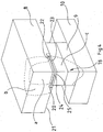
- Fig. 3 shows how an apparatus 20 according to the present invention has been disposed in the underside 21 of the slide 8.
- the apparatus according to the present invention is placed in the central area 14 of the slide and above the central area 18 of the tool 9.
- Fig. 3 which is a perspective cross sectional view along a centre plane in both the longitudinal direction and the transverse direction of the slide 8, the tool 9 and the work table 10, shows how a first part 22 and a second part 23 are separated by an interspace 24 which is filled with a suitable liquid which, in the present embodiment, consists of oil.
- the interspace 24 may be increased or reduced throughout the entire surface where the apparatus is placed, with the aid of the pressure in the oil, a satisfactory compensation for the deformation in the slide 8 can be obtained.
- Fig. 3 schematically shows how the compression pressure varies in the illustrated areas of the tool 9.
- Fig. 3 is shown schematically how much material in the areas a, b in the slide 8 and an area c in the tool 9 move in the vertical direction.
- This change in the vertical direction corresponds to an increase of the compression pressure in the areas a, b, c.
- the change in the vertical direction will be great as a result of the action of the apparatus 20 in the central area 14 of the slide 8.
- the change will be somewhat less than in the area a, but also in this area the action from the apparatus 20 can be noted.
- the action from the apparatus 20 can also be noted.
- a change is realised in the vertical direction, which gives a compression pressure in the central area 18 of the tool 9.
- Fig. 4 is a similar view to Fig. 3 , but in Fig. 4 , the oil pressure in the interspace 24 in the apparatus 20 has been increased further, whereby the first part 22 is pressed harder against the underside 21 of the slide 8 and the second part 23 presses harder against an upper part 25 on the tool 9. By such means, the compression force in the central area 18 in the tool 9 increases.
- the increased pressure is shown in that the areas a, b, c have expanded.
- the action from the apparatus 20 it will be apparent how the change in the vertical direction in the area c takes up a larger part of the central area 18 in the tool 9 in Fig. 4 than in Fig. 3 .
- Fig. 4 the oil pressure in the interspace 24 in the apparatus 20 has been increased further, whereby the first part 22 is pressed harder against the underside 21 of the slide 8 and the second part 23 presses harder against an upper part 25 on the tool 9.
- the compression force in the central area 18 in the tool 9 increases.
- the increased pressure is shown in that the
- Fig. 5 shows in plan view the apparatus 20 for compensating for deformations.
- the apparatus 20 may be likened to a membrane which, from its initial appearance, can expand and act in this expanded state and thereafter return to its initial appearance when desired.
- the apparatus 20 comprises a centrally disposed rectangular first part 22 which is surrounded by a frame section 26 which is welded together to the first part 22 along an upper welded joint.
- the upper welded joint extends all the way between the frame section 26 and the first part 22.
- the first apparatus part 22 has rounded corners 28, 29, 30, 31.
- through-going holes 32 are provided through which, for example, screws may be passed for securing the apparatus 20, for example on the clamping surface 21 ( Fig. 3 and 4 ) on a slide.
- a through-going hole 33 is provided.
- the frame section 26 follows the appearance of the first part 22 and also has rounded corners.
- Fig. 6 shows in plan view a lower side of the first part 22 which the apparatus 20 includes, as well as the frame section 26 in cross section.
- the through-going hole is provided in the centre of the first part 22.
- a circular recess 34 is provided. From this circular recess 34 extend grooves 35 out over the underside of the first part 22.
- two grooves 35, 36 extend out from the circular recess 34.
- Each respective groove 35, 36 branches in a T curve to grooves 37, 38 and 39, 40, respectively which lead out to the outer edge of the first part 22.
- the through-going hole 33, the recess 34 and the grooves 35, 36, 37, 38, 39, 40 are designed so that the liquid, e.g.
- the grooves 37, 38, 39, 40 discharge in a circumferential groove 41 which is provided in the frame section 26.
- the circumferential groove 41 extends around the whole of the frame section.
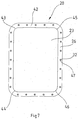
- Fig. 7 shows a plan view of the apparatus 20 and also shows a second part 23 which is fixedly welded in the frame section 26 with a lower welded joint 42.
- the second part 23 is also a rectangular plate with rounded corners 43, 44, 45, 46.
- the frame section 26 surrounds the whole of the second part 23 and also has rounded corners which are in association with the rounded corners of the second part 23.
- holes 32 are provided and surrounded by a depression 47 which is to accommodate the head of a screw which is utilised for fixing the apparatus 20 in, for example, the slide.
- Fig. 8 shows the apparatus 20 in cross section along the plane A-A as shown in Fig. 5 .
- the figure it is apparent how the first part 22 rests against the second part 23 and how the parts are disposed in relation to the frame section 26. Further, the figure shows the through-going hole 33 in the first part 22, as well as the circumferential groove 41 which is provided by recessing from the frame section 26.
- Fig. 9 is a detailed view of the area around the anchorage between the first part 22 and second part 23, respectively, and the frame section 26.
- the formation of this area is of crucial importance and affects how the apparatus 20 can move and compensate for deformations.
- great emphasis has been placed on mechanical strength properties in the formation of the upper welded joint 27 and the lower welded joint 42, as well as the circumferential groove 41.
- the circumferential groove 41 enters horizontally into the frame section 26 and has well rounded corners 48, 49 so that the forces are distributed uniformly around the surface of the groove.
- the inner surface of the groove is highly polished in order to minimize unevenness where fracture in the material may occur.
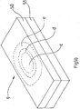
- Fig. 10 shows the tool 9 and how the apparatus according to the present invention realises a downward depression of the central part of the tool 9.
- Fig. 10 shows the tool 9 in perspective view.
- the tool 9 consists of a first tool part 50 and a second tool part 51.
- the first tool part 50 and the second tool part 51 may be distanced from one another and the blank which is to be formed in the tool 9 is placed in between these two tool parts 50, 51.
- the blank which is placed between the tool part 50 and the tool part 51 will receive a more even stamping throughout its entire surface when the hydraulic press acts on the tool 9.
- the areas c, d, e are visible in the figure.
- the areas c, d, e show areas of different pressure which the apparatus according to the present invention gives rise to when it acts on the tool 9.
- a compression pressure occurs which is greatest.
- This compression pressure declines outwardly, and so the area d shows a compression pressure which is less than the area c, and area e shows a compression pressure which is less than area d.
- the areas are shown schematically in this figure.
- the change in the vertical direction corresponds to the compression pressure, i.e. the change in the vertical direction of the material in the tool 9 is greatest in area c and less in area d and e.
- areas c, d, e show that where most change in the vertical direction is needed for realising a higher compression pressure, i.e.
- the apparatus according to the present invention also gives rise to the greatest change and compression pressure. If the apparatus according to the present invention had not been placed between the tool 9 and the slide, a more uneven distribution of the compression pressure would have been obtained in the tool 9, which would have resulted in the blank placed between the tool part 50 and part 51 would have been stamped more unevenly. The stamping action would have been greater at the edges and less in the central areas of the blank.
- FIG. 3 The embodiment of the present invention described in the foregoing may be varied in numerous different ways. It will readily be perceived by the skilled reader that the positioning of the apparatus 20 shown in Fig. 3 may be varied. For example, additional apparatuses 20 may be placed on the underside 21 if necessary. In the foregoing description, we have spoken about placing the apparatus 20 or several apparatuses of the type 20 between the slide 8 and the tool 9, in other words in the contact area 56 which is shown in Fig. 1 . It is also conceivable to place one or more apparatuses 20 on the second clamping surface 55 on the work table 10. The apparatuses 20 then act in the contact area 57 between the second clamping surface 53 on the work table 10 and the second abutment surface 55 on the tool 9. By such means, additional compensation can be attained for improving the results on pressing in the tool 9.
- the configuration of the apparatus shown in Figs. 5 , 6 , 7 and 8 may be varied.
- the size of the apparatus may also be varied.
- the configuration of the apparatus 20 is completely free and it may be designed in the manner which best suits any given practical application.
- Fig. 7 shows the holes 32 which are intended for the screw which is to secure the apparatus 20 in, for example, the slide 8 or the work table 10. Since extremely high forces act on the apparatus in the press, the securement of the apparatus must be made slightly resilient in order to prevent the anchorage screw from breaking. This somewhat resilient securing can, for example, be realised with the aid of a spring washer which is placed between the apparatus and the fixing screw in order to compensate for the configurational change which takes place when the apparatus is working. It is also conceivable to provide different types of springs which permit a certain resilient springing in order to protect the fixing screws from breaking.
Landscapes
- Engineering & Computer Science (AREA)
- Mechanical Engineering (AREA)
- Press Drives And Press Lines (AREA)
- Presses And Accessory Devices Thereof (AREA)
- Separation Using Semi-Permeable Membranes (AREA)
Claims (6)
- Vorrichtung (20) zum Ausgleich von Verformungen, wie sie während des Betriebs an einer ersten und zweiten Aufspannfläche, die für ein Werkzeug (9) in einer Presse gedacht sind, vorkommen, wobei die Aufspannflächen wechselseitig zueinander hin und voneinander weg bewegt werden können, um ein erstes (50) und ein zweites (51) Teil des Werkzeugs (9) auf das erste bzw. das zweite Werkzeugteil (50, 51) zu bzw. davon weg zu bewegen, und wobei das erste und das zweite Werkzeugteil (50, 51) eine erste und eine zweite Auflagefläche (54 bzw. 55) zum Aufliegen auf der ersten und zweiten Aufspannfläche (52 bzw. 53) der Presse aufweisen, und wobei die Verformungen einen ungleichmäßigen Druck in mindestens einem Kontaktbereich (56) zwischen dem Werkzeug (9) und den Aufspannflächen (52, 53) erzielen, und wobei die Vorrichtung Folgendes umfasst: einen Antrieb (20), der dazu ausgelegt ist, in einem Kontaktbereich (56) zwischen der Aufspannfläche (52) in der Presse und der Auflagefläche (54) am Werkzeug (9) angeordnet zu werden, wobei der Antrieb (20) dazu ausgelegt ist, bei Aktivierung mindesten einen Teil der Auflagefläche (54) des Werkzeugs (9) von der im Kontaktbereich (56) angeordneten Aufspannfläche (52) wegzudrücken, wobei der Antrieb (20) mindestens zwei Platten (22, 23) umfasst, die zwischen sich einen Zwischenraum (24) definieren, wobei die Platten von einem Rahmenabschnitt (26) umschlossen sind, der sich entlang der Seiten der Platten erstreckt, wobei der Rahmenabschnitt (26) sowohl mit der oberen als auch mit der unteren Platte (22, 23) fest verschweißt ist,
dadurch gekennzeichnet, dass die obere Platte (22) ein Durchgangsloch (33) aufweist, das mittig in der oberen Platte angebracht ist, um dem Zwischenraum (24) ein druckbeaufschlagtes Fluid zuzuführen, wobei der Zwischenraum druckbeaufschlagt ist, und dadurch gekennzeichnet, dass der von dem Antrieb auf die Auflagefläche (54) des Werkzeugs (9) ausgeübte Kompressionsdruck von einem mittleren Bereich (c) des Werkzeugs nach außen hin abnimmt, wenn der Zwischenraum druckbeaufschlagt ist. - Vorrichtung nach Anspruch 1, dadurch gekennzeichnet, dass der Antrieb (20) eine flache Gestaltung aufweist.
- Vorrichtung nach einem der Ansprüche 1-2, dadurch gekennzeichnet, dass der Rahmenabschnitt (26) entlang der Umfangslänge der Platten (22, 23) mit einer Umlaufnut (41) versehen ist.
- Vorrichtung nach einem der Ansprüche 1-3, dadurch gekennzeichnet, dass die Dicke des Rahmenabschnitts (26) auf jeder Seite der Nut (41) geringer ist als die Dicke jeder der Platten (22, 23).
- Vorrichtung nach Anspruch 3 oder 4, dadurch gekennzeichnet, dass die Nut geschliffen ist, um die Tendenz des Materials, zu brechen, zu verringern.
- Vorrichtung nach einem der Ansprüche 1 bis 5, dadurch gekennzeichnet, dass eine Unterseite der oberen Platte (22) mit Nuten (35, 36, 37, 38, 39, 40) versehen ist, wobei die Nuten mit dem Durchgangsloch (33) verbunden sind.
Applications Claiming Priority (2)
| Application Number | Priority Date | Filing Date | Title |
|---|---|---|---|
| SE0303402A SE527061C2 (sv) | 2003-12-17 | 2003-12-17 | Membran |
| PCT/SE2004/001855 WO2005058590A1 (en) | 2003-12-17 | 2004-12-14 | Apparatus and method for compensating for stress deformations in a press |
Publications (2)
| Publication Number | Publication Date |
|---|---|
| EP1706258A1 EP1706258A1 (de) | 2006-10-04 |
| EP1706258B1 true EP1706258B1 (de) | 2016-06-15 |
Family
ID=30439718
Family Applications (1)
| Application Number | Title | Priority Date | Filing Date |
|---|---|---|---|
| EP04809041.9A Expired - Lifetime EP1706258B1 (de) | 2003-12-17 | 2004-12-14 | Vorrichtung zum ausgleich von spannungsverformungen in einer presse |
Country Status (7)
| Country | Link |
|---|---|
| US (2) | US8342085B2 (de) |
| EP (1) | EP1706258B1 (de) |
| JP (1) | JP4866245B2 (de) |
| CN (1) | CN1894091B (de) |
| CA (1) | CA2548570C (de) |
| SE (1) | SE527061C2 (de) |
| WO (1) | WO2005058590A1 (de) |
Families Citing this family (9)
| Publication number | Priority date | Publication date | Assignee | Title |
|---|---|---|---|---|
| US7819163B2 (en) | 2003-09-16 | 2010-10-26 | Masonite Corporation | Automated door assembly system and method |
| US9314983B2 (en) | 2010-07-28 | 2016-04-19 | Masonite Corporation | Automated door assembly, press, and adhesive therefor |
| EP2598297B1 (de) | 2010-07-28 | 2016-10-05 | Masonite Corporation | Automatisierte türanordnung |
| CN102357636B (zh) * | 2011-08-23 | 2013-09-18 | 山东理工大学 | 压制件的打击力误差控制方法 |
| AT512465B1 (de) * | 2012-02-10 | 2014-01-15 | Trumpf Maschinen Austria Gmbh | Presstisch oder pressbalken mit verstellbarem balkenelement |
| CN102601194B (zh) * | 2012-03-16 | 2015-05-13 | 中国第一汽车股份有限公司 | 一种针对压力机挠度变形的大型冲压模具型面补偿方法 |
| MX2015013206A (es) | 2013-03-15 | 2016-04-15 | Masonite Corp | Sistemas y metodos de montaje automatizado de puerta. |
| US9511573B2 (en) | 2013-07-25 | 2016-12-06 | Masonite Corporation | Automated door assembly, press, and adhesive therefor |
| FR3060446B1 (fr) * | 2016-12-20 | 2019-05-31 | Porcher Industries | Presse chauffante, ensemble de pressage, procede de reglage et utilisations d'une telle presse chauffante. |
Citations (2)
| Publication number | Priority date | Publication date | Assignee | Title |
|---|---|---|---|---|
| US4557792A (en) * | 1983-04-15 | 1985-12-10 | Hitachi, Ltd. | Hot press |
| AT6467U1 (de) * | 2002-11-07 | 2003-11-25 | Engel Austria Gmbh | Einrichtung zum spritzgiessen |
Family Cites Families (22)
| Publication number | Priority date | Publication date | Assignee | Title |
|---|---|---|---|---|
| US2107587A (en) * | 1934-08-20 | 1938-02-08 | Papercrete Ltd | Forming of paperboards |
| US2066085A (en) * | 1935-10-07 | 1936-12-29 | Lawrence V Whistler | Methods of embossing sheet-metal |
| US2869173A (en) * | 1956-06-11 | 1959-01-20 | Hartesveldt Van | Safety device for diaphragm actuated means |
| DE1195480B (de) * | 1963-08-29 | 1965-06-24 | Eugen Siempelkamp | Presse, insbesondere Etagenpresse |
| DE1703297A1 (de) | 1968-04-29 | 1972-02-17 | Freudenberg Carl Fa | Heizplattenpresse mit selbstkompensierenden Zylinderkolbenanordnungen |
| US3619310A (en) * | 1969-11-06 | 1971-11-09 | Ici Ltd | Method of making liquid-filled pressure-distributing pads used in presses |
| US4190484A (en) * | 1975-10-20 | 1980-02-26 | Rembert Duvelius | Press for producing shaped articles |
| DE3028401C2 (de) * | 1980-07-26 | 1982-09-23 | Wagener Schwelm GmbH & Co, 5830 Schwelm | Vorrichtung für die Reparatur und zum Endlosmachen von Fördergurten aus Gummi oder Kunststoff |
| JPS61262500A (ja) * | 1985-05-15 | 1986-11-20 | Kootaki Kk | プレス装置 |
| DE3636600A1 (de) * | 1986-10-28 | 1988-05-05 | Hoesch Maschinenfabrik Ag | Heizpresse zum verpressen von technischen laminaten |
| JPH02118695A (ja) * | 1988-10-28 | 1990-05-02 | Casio Comput Co Ltd | 離鍵タッチレスポンス装置 |
| JPH07276100A (ja) * | 1994-04-11 | 1995-10-24 | Kootaki Seiki Kk | プレス装置 |
| JPH0825388A (ja) * | 1994-07-14 | 1996-01-30 | Mitsubishi Electric Corp | 加工用プレス装置およびその装置を用いた加圧成形方法 |
| JPH08164500A (ja) * | 1994-12-14 | 1996-06-25 | Nisshinbo Ind Inc | 分散加圧型プレス装置 |
| JP3359266B2 (ja) * | 1997-08-28 | 2002-12-24 | ダイハツ工業株式会社 | 樹脂シート成形プレス |
| US6142763A (en) * | 1998-12-30 | 2000-11-07 | International Thermoforming Systems, Inc. | Thermal presses for forming articles from a web of thermoplastic material |
| DE19937694B4 (de) * | 1999-08-10 | 2004-11-25 | Siempelkamp Maschinen- Und Anlagenbau Gmbh & Co. Kg | Plattenpresse, insbesondere Einetagenpresse |
| CN2454124Y (zh) * | 2000-08-23 | 2001-10-17 | 大连第一锻压机械设备厂 | 浮动群冲液压机 |
| DE10043030A1 (de) | 2000-09-01 | 2002-03-21 | Dieffenbacher Gmbh Maschf | Kurztaktpresse |
| US6487888B1 (en) * | 2000-10-05 | 2002-12-03 | Valiant Corporation | Hemming machine |
| US6752901B2 (en) * | 2002-04-05 | 2004-06-22 | Heinrich Wemhoener Gmbh & Co. Kg | Coating press for sheet-like work-pieces |
| US7004007B2 (en) * | 2003-10-14 | 2006-02-28 | General Motors Corporation | Die cushion apparatus for hot stretch-forming |
-
2003
- 2003-12-17 SE SE0303402A patent/SE527061C2/sv not_active IP Right Cessation
-
2004
- 2004-12-14 EP EP04809041.9A patent/EP1706258B1/de not_active Expired - Lifetime
- 2004-12-14 JP JP2006545284A patent/JP4866245B2/ja not_active Expired - Fee Related
- 2004-12-14 WO PCT/SE2004/001855 patent/WO2005058590A1/en not_active Ceased
- 2004-12-14 US US10/582,591 patent/US8342085B2/en not_active Expired - Fee Related
- 2004-12-14 CN CN2004800375685A patent/CN1894091B/zh not_active Expired - Fee Related
- 2004-12-14 CA CA2548570A patent/CA2548570C/en not_active Expired - Fee Related
-
2010
- 2010-08-18 US US12/858,641 patent/US8387524B2/en not_active Expired - Fee Related
Patent Citations (2)
| Publication number | Priority date | Publication date | Assignee | Title |
|---|---|---|---|---|
| US4557792A (en) * | 1983-04-15 | 1985-12-10 | Hitachi, Ltd. | Hot press |
| AT6467U1 (de) * | 2002-11-07 | 2003-11-25 | Engel Austria Gmbh | Einrichtung zum spritzgiessen |
Also Published As
| Publication number | Publication date |
|---|---|
| SE527061C2 (sv) | 2005-12-13 |
| US20100307217A1 (en) | 2010-12-09 |
| CA2548570A1 (en) | 2005-06-30 |
| US8387524B2 (en) | 2013-03-05 |
| JP2007514551A (ja) | 2007-06-07 |
| CN1894091A (zh) | 2007-01-10 |
| SE0303402L (sv) | 2005-06-18 |
| SE0303402D0 (sv) | 2003-12-17 |
| EP1706258A1 (de) | 2006-10-04 |
| JP4866245B2 (ja) | 2012-02-01 |
| US20070295054A1 (en) | 2007-12-27 |
| WO2005058590A1 (en) | 2005-06-30 |
| US8342085B2 (en) | 2013-01-01 |
| CN1894091B (zh) | 2011-01-19 |
| CA2548570C (en) | 2013-01-22 |
Similar Documents
| Publication | Publication Date | Title |
|---|---|---|
| US8387524B2 (en) | Apparatus and method for compensating for stress deformation in a press | |
| KR100345288B1 (ko) | 무금형 성형장치 | |
| JP4781380B2 (ja) | プレス加工装置及びプレス加工方法 | |
| CN207592473U (zh) | 整形装置 | |
| CN102896191B (zh) | 小圆角整形装置及其整形方法 | |
| JPH04305321A (ja) | 薄板素材の絞り成形装置 | |
| KR20170087680A (ko) | 가공오차 조정이 가능한 벤딩금형 핀치다이 | |
| EP1539394B1 (de) | Vorrichtung und verfahren zum expansionsformen | |
| EP2483006B1 (de) | System aus platte und druckring für eine strangpresse und strangpresse mit einem derartigen system | |
| MXPA06006713A (en) | Apparatus and method for compensating for stress deformations in a press | |
| JPS60148628A (ja) | 角筒容器絞り加工用プレス型 | |
| US7681427B2 (en) | Method and device for the production and/or machining of pieces | |
| JPH08117880A (ja) | プレス装置 | |
| MX2007010014A (es) | Chapa de puerta de alta definicion y metodo para fabricar la misma. | |
| EP3283242B1 (de) | Druckverteiler zum pressen von metallen und matrize mit diesem druckverteiler | |
| US20230328933A1 (en) | Integrated heat spreader | |
| KR102635262B1 (ko) | 곡면 가공 장치 | |
| CN221362237U (zh) | 一种汽车c柱加强板冲压模具 | |
| KR20170005611A (ko) | 편심방지장치가 구비된 가압프레스 | |
| JP2025086918A (ja) | 金型 | |
| CN119346740A (zh) | 冲压组件及冲压方法 | |
| KR20250042497A (ko) | 프레스 금형 장치 | |
| KR20250177163A (ko) | 프레스 금형 장치 | |
| KR20240010142A (ko) | 밀림 버 형성 방지를 위한 챔퍼 가공 방법 및 상기 밀림 버 형성 방지를 위한 챔퍼 가공 방법이 적용된 밀림 버 형성 방지를 위한 챔퍼 가공 장치 | |
| JPH0337786Y2 (de) |
Legal Events
| Date | Code | Title | Description |
|---|---|---|---|
| PUAI | Public reference made under article 153(3) epc to a published international application that has entered the european phase |
Free format text: ORIGINAL CODE: 0009012 |
|
| 17P | Request for examination filed |
Effective date: 20060717 |
|
| AK | Designated contracting states |
Kind code of ref document: A1 Designated state(s): AT BE BG CH CY CZ DE DK EE ES FI FR GB GR HU IE IS IT LI LT LU MC NL PL PT RO SE SI SK TR |
|
| DAX | Request for extension of the european patent (deleted) | ||
| 17Q | First examination report despatched |
Effective date: 20111221 |
|
| RIC1 | Information provided on ipc code assigned before grant |
Ipc: B30B 15/00 20060101ALI20140304BHEP Ipc: B30B 1/32 20060101ALI20140304BHEP Ipc: B30B 15/06 20060101AFI20140304BHEP |
|
| GRAP | Despatch of communication of intention to grant a patent |
Free format text: ORIGINAL CODE: EPIDOSNIGR1 |
|
| INTG | Intention to grant announced |
Effective date: 20160105 |
|
| GRAS | Grant fee paid |
Free format text: ORIGINAL CODE: EPIDOSNIGR3 |
|
| GRAA | (expected) grant |
Free format text: ORIGINAL CODE: 0009210 |
|
| AK | Designated contracting states |
Kind code of ref document: B1 Designated state(s): AT BE BG CH CY CZ DE DK EE ES FI FR GB GR HU IE IS IT LI LT LU MC NL PL PT RO SE SI SK TR |
|
| REG | Reference to a national code |
Ref country code: CH Ref legal event code: EP Ref country code: GB Ref legal event code: FG4D |
|
| REG | Reference to a national code |
Ref country code: IE Ref legal event code: FG4D |
|
| REG | Reference to a national code |
Ref country code: AT Ref legal event code: REF Ref document number: 806275 Country of ref document: AT Kind code of ref document: T Effective date: 20160715 |
|
| REG | Reference to a national code |
Ref country code: DE Ref legal event code: R096 Ref document number: 602004049453 Country of ref document: DE |
|
| REG | Reference to a national code |
Ref country code: LT Ref legal event code: MG4D |
|
| REG | Reference to a national code |
Ref country code: NL Ref legal event code: MP Effective date: 20160615 |
|
| PG25 | Lapsed in a contracting state [announced via postgrant information from national office to epo] |
Ref country code: LT Free format text: LAPSE BECAUSE OF FAILURE TO SUBMIT A TRANSLATION OF THE DESCRIPTION OR TO PAY THE FEE WITHIN THE PRESCRIBED TIME-LIMIT Effective date: 20160615 Ref country code: FI Free format text: LAPSE BECAUSE OF FAILURE TO SUBMIT A TRANSLATION OF THE DESCRIPTION OR TO PAY THE FEE WITHIN THE PRESCRIBED TIME-LIMIT Effective date: 20160615 |
|
| REG | Reference to a national code |
Ref country code: AT Ref legal event code: MK05 Ref document number: 806275 Country of ref document: AT Kind code of ref document: T Effective date: 20160615 |
|
| PG25 | Lapsed in a contracting state [announced via postgrant information from national office to epo] |
Ref country code: NL Free format text: LAPSE BECAUSE OF FAILURE TO SUBMIT A TRANSLATION OF THE DESCRIPTION OR TO PAY THE FEE WITHIN THE PRESCRIBED TIME-LIMIT Effective date: 20160615 Ref country code: GR Free format text: LAPSE BECAUSE OF FAILURE TO SUBMIT A TRANSLATION OF THE DESCRIPTION OR TO PAY THE FEE WITHIN THE PRESCRIBED TIME-LIMIT Effective date: 20160916 Ref country code: SE Free format text: LAPSE BECAUSE OF FAILURE TO SUBMIT A TRANSLATION OF THE DESCRIPTION OR TO PAY THE FEE WITHIN THE PRESCRIBED TIME-LIMIT Effective date: 20160615 |
|
| PG25 | Lapsed in a contracting state [announced via postgrant information from national office to epo] |
Ref country code: EE Free format text: LAPSE BECAUSE OF FAILURE TO SUBMIT A TRANSLATION OF THE DESCRIPTION OR TO PAY THE FEE WITHIN THE PRESCRIBED TIME-LIMIT Effective date: 20160615 Ref country code: SK Free format text: LAPSE BECAUSE OF FAILURE TO SUBMIT A TRANSLATION OF THE DESCRIPTION OR TO PAY THE FEE WITHIN THE PRESCRIBED TIME-LIMIT Effective date: 20160615 Ref country code: IT Free format text: LAPSE BECAUSE OF FAILURE TO SUBMIT A TRANSLATION OF THE DESCRIPTION OR TO PAY THE FEE WITHIN THE PRESCRIBED TIME-LIMIT Effective date: 20160615 Ref country code: CZ Free format text: LAPSE BECAUSE OF FAILURE TO SUBMIT A TRANSLATION OF THE DESCRIPTION OR TO PAY THE FEE WITHIN THE PRESCRIBED TIME-LIMIT Effective date: 20160615 Ref country code: IS Free format text: LAPSE BECAUSE OF FAILURE TO SUBMIT A TRANSLATION OF THE DESCRIPTION OR TO PAY THE FEE WITHIN THE PRESCRIBED TIME-LIMIT Effective date: 20161015 Ref country code: RO Free format text: LAPSE BECAUSE OF FAILURE TO SUBMIT A TRANSLATION OF THE DESCRIPTION OR TO PAY THE FEE WITHIN THE PRESCRIBED TIME-LIMIT Effective date: 20160615 |
|
| PG25 | Lapsed in a contracting state [announced via postgrant information from national office to epo] |
Ref country code: BE Free format text: LAPSE BECAUSE OF FAILURE TO SUBMIT A TRANSLATION OF THE DESCRIPTION OR TO PAY THE FEE WITHIN THE PRESCRIBED TIME-LIMIT Effective date: 20160615 Ref country code: PL Free format text: LAPSE BECAUSE OF FAILURE TO SUBMIT A TRANSLATION OF THE DESCRIPTION OR TO PAY THE FEE WITHIN THE PRESCRIBED TIME-LIMIT Effective date: 20160615 Ref country code: ES Free format text: LAPSE BECAUSE OF FAILURE TO SUBMIT A TRANSLATION OF THE DESCRIPTION OR TO PAY THE FEE WITHIN THE PRESCRIBED TIME-LIMIT Effective date: 20160615 Ref country code: PT Free format text: LAPSE BECAUSE OF FAILURE TO SUBMIT A TRANSLATION OF THE DESCRIPTION OR TO PAY THE FEE WITHIN THE PRESCRIBED TIME-LIMIT Effective date: 20161017 Ref country code: AT Free format text: LAPSE BECAUSE OF FAILURE TO SUBMIT A TRANSLATION OF THE DESCRIPTION OR TO PAY THE FEE WITHIN THE PRESCRIBED TIME-LIMIT Effective date: 20160615 |
|
| REG | Reference to a national code |
Ref country code: DE Ref legal event code: R097 Ref document number: 602004049453 Country of ref document: DE |
|
| PLBE | No opposition filed within time limit |
Free format text: ORIGINAL CODE: 0009261 |
|
| STAA | Information on the status of an ep patent application or granted ep patent |
Free format text: STATUS: NO OPPOSITION FILED WITHIN TIME LIMIT |
|
| 26N | No opposition filed |
Effective date: 20170316 |
|
| PG25 | Lapsed in a contracting state [announced via postgrant information from national office to epo] |
Ref country code: DK Free format text: LAPSE BECAUSE OF FAILURE TO SUBMIT A TRANSLATION OF THE DESCRIPTION OR TO PAY THE FEE WITHIN THE PRESCRIBED TIME-LIMIT Effective date: 20160615 |
|
| REG | Reference to a national code |
Ref country code: CH Ref legal event code: PL |
|
| GBPC | Gb: european patent ceased through non-payment of renewal fee |
Effective date: 20161214 |
|
| PG25 | Lapsed in a contracting state [announced via postgrant information from national office to epo] |
Ref country code: SI Free format text: LAPSE BECAUSE OF FAILURE TO SUBMIT A TRANSLATION OF THE DESCRIPTION OR TO PAY THE FEE WITHIN THE PRESCRIBED TIME-LIMIT Effective date: 20160615 |
|
| PG25 | Lapsed in a contracting state [announced via postgrant information from national office to epo] |
Ref country code: MC Free format text: LAPSE BECAUSE OF FAILURE TO SUBMIT A TRANSLATION OF THE DESCRIPTION OR TO PAY THE FEE WITHIN THE PRESCRIBED TIME-LIMIT Effective date: 20160615 |
|
| REG | Reference to a national code |
Ref country code: FR Ref legal event code: ST Effective date: 20170831 |
|
| REG | Reference to a national code |
Ref country code: IE Ref legal event code: MM4A |
|
| PG25 | Lapsed in a contracting state [announced via postgrant information from national office to epo] |
Ref country code: LI Free format text: LAPSE BECAUSE OF NON-PAYMENT OF DUE FEES Effective date: 20161231 Ref country code: LU Free format text: LAPSE BECAUSE OF NON-PAYMENT OF DUE FEES Effective date: 20161214 Ref country code: FR Free format text: LAPSE BECAUSE OF NON-PAYMENT OF DUE FEES Effective date: 20170102 Ref country code: CH Free format text: LAPSE BECAUSE OF NON-PAYMENT OF DUE FEES Effective date: 20161231 |
|
| PG25 | Lapsed in a contracting state [announced via postgrant information from national office to epo] |
Ref country code: IE Free format text: LAPSE BECAUSE OF NON-PAYMENT OF DUE FEES Effective date: 20161214 Ref country code: GB Free format text: LAPSE BECAUSE OF NON-PAYMENT OF DUE FEES Effective date: 20161214 |
|
| PG25 | Lapsed in a contracting state [announced via postgrant information from national office to epo] |
Ref country code: HU Free format text: LAPSE BECAUSE OF FAILURE TO SUBMIT A TRANSLATION OF THE DESCRIPTION OR TO PAY THE FEE WITHIN THE PRESCRIBED TIME-LIMIT; INVALID AB INITIO Effective date: 20041214 Ref country code: CY Free format text: LAPSE BECAUSE OF FAILURE TO SUBMIT A TRANSLATION OF THE DESCRIPTION OR TO PAY THE FEE WITHIN THE PRESCRIBED TIME-LIMIT Effective date: 20160615 |
|
| PG25 | Lapsed in a contracting state [announced via postgrant information from national office to epo] |
Ref country code: TR Free format text: LAPSE BECAUSE OF FAILURE TO SUBMIT A TRANSLATION OF THE DESCRIPTION OR TO PAY THE FEE WITHIN THE PRESCRIBED TIME-LIMIT Effective date: 20160615 |
|
| PG25 | Lapsed in a contracting state [announced via postgrant information from national office to epo] |
Ref country code: BG Free format text: LAPSE BECAUSE OF FAILURE TO SUBMIT A TRANSLATION OF THE DESCRIPTION OR TO PAY THE FEE WITHIN THE PRESCRIBED TIME-LIMIT Effective date: 20160615 |
|
| PGFP | Annual fee paid to national office [announced via postgrant information from national office to epo] |
Ref country code: DE Payment date: 20201117 Year of fee payment: 17 |
|
| REG | Reference to a national code |
Ref country code: DE Ref legal event code: R119 Ref document number: 602004049453 Country of ref document: DE |
|
| PG25 | Lapsed in a contracting state [announced via postgrant information from national office to epo] |
Ref country code: DE Free format text: LAPSE BECAUSE OF NON-PAYMENT OF DUE FEES Effective date: 20220701 |