EP1704087B1 - Method and apparatus for braking and maneuvering - Google Patents
Method and apparatus for braking and maneuvering Download PDFInfo
- Publication number
- EP1704087B1 EP1704087B1 EP04821791.3A EP04821791A EP1704087B1 EP 1704087 B1 EP1704087 B1 EP 1704087B1 EP 04821791 A EP04821791 A EP 04821791A EP 1704087 B1 EP1704087 B1 EP 1704087B1
- Authority
- EP
- European Patent Office
- Prior art keywords
- aircraft
- stator
- rotor
- landing gear
- wheel
- Prior art date
- Legal status (The legal status is an assumption and is not a legal conclusion. Google has not performed a legal analysis and makes no representation as to the accuracy of the status listed.)
- Revoked
Links
- 238000000034 method Methods 0.000 title claims description 60
- 230000004907 flux Effects 0.000 claims description 42
- 230000005291 magnetic effect Effects 0.000 claims description 39
- 230000009471 action Effects 0.000 claims description 26
- 230000033001 locomotion Effects 0.000 claims description 16
- 238000004146 energy storage Methods 0.000 claims description 14
- 230000003993 interaction Effects 0.000 claims description 13
- 238000013461 design Methods 0.000 claims description 11
- 230000003247 decreasing effect Effects 0.000 claims description 4
- 239000003575 carbonaceous material Substances 0.000 claims description 3
- 230000006698 induction Effects 0.000 claims description 3
- 238000012546 transfer Methods 0.000 claims description 3
- 230000003068 static effect Effects 0.000 claims description 2
- 230000021715 photosynthesis, light harvesting Effects 0.000 claims 4
- 238000002156 mixing Methods 0.000 claims 2
- 238000006243 chemical reaction Methods 0.000 claims 1
- 230000001172 regenerating effect Effects 0.000 description 12
- 230000008901 benefit Effects 0.000 description 10
- 230000000694 effects Effects 0.000 description 8
- 238000005096 rolling process Methods 0.000 description 6
- 238000004804 winding Methods 0.000 description 6
- OKTJSMMVPCPJKN-UHFFFAOYSA-N Carbon Chemical compound [C] OKTJSMMVPCPJKN-UHFFFAOYSA-N 0.000 description 5
- RYGMFSIKBFXOCR-UHFFFAOYSA-N Copper Chemical compound [Cu] RYGMFSIKBFXOCR-UHFFFAOYSA-N 0.000 description 5
- 229910052799 carbon Inorganic materials 0.000 description 5
- 239000010949 copper Substances 0.000 description 5
- 229910052802 copper Inorganic materials 0.000 description 5
- 238000012423 maintenance Methods 0.000 description 5
- 230000002829 reductive effect Effects 0.000 description 4
- 230000002441 reversible effect Effects 0.000 description 4
- 230000005355 Hall effect Effects 0.000 description 3
- 239000004020 conductor Substances 0.000 description 3
- 230000006870 function Effects 0.000 description 3
- 230000003287 optical effect Effects 0.000 description 3
- 230000009467 reduction Effects 0.000 description 3
- XEEYBQQBJWHFJM-UHFFFAOYSA-N Iron Chemical group [Fe] XEEYBQQBJWHFJM-UHFFFAOYSA-N 0.000 description 2
- 229910000831 Steel Inorganic materials 0.000 description 2
- 230000001133 acceleration Effects 0.000 description 2
- XAGFODPZIPBFFR-UHFFFAOYSA-N aluminium Chemical compound [Al] XAGFODPZIPBFFR-UHFFFAOYSA-N 0.000 description 2
- 229910052782 aluminium Inorganic materials 0.000 description 2
- 229910052790 beryllium Inorganic materials 0.000 description 2
- ATBAMAFKBVZNFJ-UHFFFAOYSA-N beryllium atom Chemical compound [Be] ATBAMAFKBVZNFJ-UHFFFAOYSA-N 0.000 description 2
- 239000002131 composite material Substances 0.000 description 2
- 238000010276 construction Methods 0.000 description 2
- 239000011162 core material Substances 0.000 description 2
- 230000001419 dependent effect Effects 0.000 description 2
- 238000011161 development Methods 0.000 description 2
- 230000018109 developmental process Effects 0.000 description 2
- 238000010586 diagram Methods 0.000 description 2
- 230000006872 improvement Effects 0.000 description 2
- 230000008569 process Effects 0.000 description 2
- 229910052709 silver Inorganic materials 0.000 description 2
- 239000004332 silver Substances 0.000 description 2
- 239000007787 solid Substances 0.000 description 2
- 230000000087 stabilizing effect Effects 0.000 description 2
- 239000010959 steel Substances 0.000 description 2
- 229910000838 Al alloy Inorganic materials 0.000 description 1
- 229910052779 Neodymium Inorganic materials 0.000 description 1
- BQCADISMDOOEFD-UHFFFAOYSA-N Silver Chemical compound [Ag] BQCADISMDOOEFD-UHFFFAOYSA-N 0.000 description 1
- 230000032683 aging Effects 0.000 description 1
- 229910045601 alloy Inorganic materials 0.000 description 1
- 239000000956 alloy Substances 0.000 description 1
- 230000000712 assembly Effects 0.000 description 1
- 238000000429 assembly Methods 0.000 description 1
- 230000005540 biological transmission Effects 0.000 description 1
- 239000003990 capacitor Substances 0.000 description 1
- 229920001940 conductive polymer Polymers 0.000 description 1
- 238000011109 contamination Methods 0.000 description 1
- 238000001816 cooling Methods 0.000 description 1
- 230000007423 decrease Effects 0.000 description 1
- 230000003292 diminished effect Effects 0.000 description 1
- 230000003628 erosive effect Effects 0.000 description 1
- 239000003302 ferromagnetic material Substances 0.000 description 1
- 239000000446 fuel Substances 0.000 description 1
- 230000000977 initiatory effect Effects 0.000 description 1
- 238000002955 isolation Methods 0.000 description 1
- 238000013178 mathematical model Methods 0.000 description 1
- 230000007246 mechanism Effects 0.000 description 1
- 238000012986 modification Methods 0.000 description 1
- 230000004048 modification Effects 0.000 description 1
- QEFYFXOXNSNQGX-UHFFFAOYSA-N neodymium atom Chemical compound [Nd] QEFYFXOXNSNQGX-UHFFFAOYSA-N 0.000 description 1
- 235000012771 pancakes Nutrition 0.000 description 1
- 230000000737 periodic effect Effects 0.000 description 1
- 238000002360 preparation method Methods 0.000 description 1
- 230000006641 stabilisation Effects 0.000 description 1
- 238000011105 stabilization Methods 0.000 description 1
- 238000012360 testing method Methods 0.000 description 1
Images


Classifications
-
- B—PERFORMING OPERATIONS; TRANSPORTING
- B64—AIRCRAFT; AVIATION; COSMONAUTICS
- B64C—AEROPLANES; HELICOPTERS
- B64C25/00—Alighting gear
- B64C25/32—Alighting gear characterised by elements which contact the ground or similar surface
- B64C25/405—Powered wheels, e.g. for taxing
-
- B—PERFORMING OPERATIONS; TRANSPORTING
- B64—AIRCRAFT; AVIATION; COSMONAUTICS
- B64C—AEROPLANES; HELICOPTERS
- B64C25/00—Alighting gear
- B64C25/32—Alighting gear characterised by elements which contact the ground or similar surface
- B64C25/42—Arrangement or adaptation of brakes
-
- B—PERFORMING OPERATIONS; TRANSPORTING
- B60—VEHICLES IN GENERAL
- B60L—PROPULSION OF ELECTRICALLY-PROPELLED VEHICLES; SUPPLYING ELECTRIC POWER FOR AUXILIARY EQUIPMENT OF ELECTRICALLY-PROPELLED VEHICLES; ELECTRODYNAMIC BRAKE SYSTEMS FOR VEHICLES IN GENERAL; MAGNETIC SUSPENSION OR LEVITATION FOR VEHICLES; MONITORING OPERATING VARIABLES OF ELECTRICALLY-PROPELLED VEHICLES; ELECTRIC SAFETY DEVICES FOR ELECTRICALLY-PROPELLED VEHICLES
- B60L7/00—Electrodynamic brake systems for vehicles in general
- B60L7/24—Electrodynamic brake systems for vehicles in general with additional mechanical or electromagnetic braking
- B60L7/26—Controlling the braking effect
-
- B—PERFORMING OPERATIONS; TRANSPORTING
- B64—AIRCRAFT; AVIATION; COSMONAUTICS
- B64C—AEROPLANES; HELICOPTERS
- B64C25/00—Alighting gear
- B64C25/32—Alighting gear characterised by elements which contact the ground or similar surface
- B64C25/34—Alighting gear characterised by elements which contact the ground or similar surface wheeled type, e.g. multi-wheeled bogies
-
- B—PERFORMING OPERATIONS; TRANSPORTING
- B64—AIRCRAFT; AVIATION; COSMONAUTICS
- B64C—AEROPLANES; HELICOPTERS
- B64C25/00—Alighting gear
- B64C25/32—Alighting gear characterised by elements which contact the ground or similar surface
- B64C25/50—Steerable undercarriages; Shimmy-damping
-
- B—PERFORMING OPERATIONS; TRANSPORTING
- B60—VEHICLES IN GENERAL
- B60L—PROPULSION OF ELECTRICALLY-PROPELLED VEHICLES; SUPPLYING ELECTRIC POWER FOR AUXILIARY EQUIPMENT OF ELECTRICALLY-PROPELLED VEHICLES; ELECTRODYNAMIC BRAKE SYSTEMS FOR VEHICLES IN GENERAL; MAGNETIC SUSPENSION OR LEVITATION FOR VEHICLES; MONITORING OPERATING VARIABLES OF ELECTRICALLY-PROPELLED VEHICLES; ELECTRIC SAFETY DEVICES FOR ELECTRICALLY-PROPELLED VEHICLES
- B60L2220/00—Electrical machine types; Structures or applications thereof
- B60L2220/40—Electrical machine applications
- B60L2220/44—Wheel Hub motors, i.e. integrated in the wheel hub
-
- B—PERFORMING OPERATIONS; TRANSPORTING
- B60—VEHICLES IN GENERAL
- B60L—PROPULSION OF ELECTRICALLY-PROPELLED VEHICLES; SUPPLYING ELECTRIC POWER FOR AUXILIARY EQUIPMENT OF ELECTRICALLY-PROPELLED VEHICLES; ELECTRODYNAMIC BRAKE SYSTEMS FOR VEHICLES IN GENERAL; MAGNETIC SUSPENSION OR LEVITATION FOR VEHICLES; MONITORING OPERATING VARIABLES OF ELECTRICALLY-PROPELLED VEHICLES; ELECTRIC SAFETY DEVICES FOR ELECTRICALLY-PROPELLED VEHICLES
- B60L2240/00—Control parameters of input or output; Target parameters
- B60L2240/10—Vehicle control parameters
- B60L2240/30—Parking brake position
-
- B—PERFORMING OPERATIONS; TRANSPORTING
- B60—VEHICLES IN GENERAL
- B60L—PROPULSION OF ELECTRICALLY-PROPELLED VEHICLES; SUPPLYING ELECTRIC POWER FOR AUXILIARY EQUIPMENT OF ELECTRICALLY-PROPELLED VEHICLES; ELECTRODYNAMIC BRAKE SYSTEMS FOR VEHICLES IN GENERAL; MAGNETIC SUSPENSION OR LEVITATION FOR VEHICLES; MONITORING OPERATING VARIABLES OF ELECTRICALLY-PROPELLED VEHICLES; ELECTRIC SAFETY DEVICES FOR ELECTRICALLY-PROPELLED VEHICLES
- B60L2250/00—Driver interactions
- B60L2250/24—Driver interactions by lever actuation
-
- Y—GENERAL TAGGING OF NEW TECHNOLOGICAL DEVELOPMENTS; GENERAL TAGGING OF CROSS-SECTIONAL TECHNOLOGIES SPANNING OVER SEVERAL SECTIONS OF THE IPC; TECHNICAL SUBJECTS COVERED BY FORMER USPC CROSS-REFERENCE ART COLLECTIONS [XRACs] AND DIGESTS
- Y02—TECHNOLOGIES OR APPLICATIONS FOR MITIGATION OR ADAPTATION AGAINST CLIMATE CHANGE
- Y02T—CLIMATE CHANGE MITIGATION TECHNOLOGIES RELATED TO TRANSPORTATION
- Y02T50/00—Aeronautics or air transport
- Y02T50/80—Energy efficient operational measures, e.g. ground operations or mission management
Definitions
- the Invention relates to aircraft landing gear and, more specifically to an integrated wheel hub motor/generator, regenerative braking and/or motorized braking method for an aircraft landing gear system, which reduces wear of the braking system and the associated tires while improving stability of said aircraft and reducing the need for maintenance due to wear.
- the current state of the art for providing braking systems for aircraft uses stators and rotors, which are forced into physical contact with each other thus generating friction heat that introduces wear of the associated disks and requires periodic maintenance to replace the worn parts.
- aircraft are required to maneuver within the defined taxies, runways and terminals.
- One such requirement is the 180-degree turn that places an upper limit on the aircraft allowed for a particular runway based upon the width of the runway and the ability of said aircraft in conducting a 180-degree turn there on within the physical width of said runway.
- Current landing gear provides limited abilities to perform such 180-degree turns.
- a further object of the invention is to reduce wear of the components involved in the landing gear and braking system, add stability to the aircraft structure, and increase reliability, while reducing the needed maintenance associated with current friction braking systems.
- Another objective is to reduce the wear of the tires of said aircraft due to sliding friction wear due to touchdown by closely matching the landing gear tires radial velocity with that of the relative ground velocity such that when touchdown occurs the difference in velocity is greatly minimized, thus greatly reducing the sliding friction wear of said tires associated with the touchdown of the landing gear tires with the runway landing surface.
- This sliding friction which is present in the current state of the art, creates an associated wear that affects tire performance thus affecting safety.
- a further object is to provide a means of motive force for the purpose of conducting taxiing and ground maneuvers of said aircraft, which contributes to increased efficiency, maneuverability, stability and safety of said aircraft.
- a further object is to provide a means of motive force for the purpose of assisting in takeoff, which reduces the required takeoff distance for the aircraft, which also contributes to increased efficiency, maneuverability, stability and safety of said aircraft.
- the present invention provides a unique means of aircraft braking wherein the use of regenerative braking and/or motorized braking is applied in a manner, which creates advantages over prior art friction braking systems. This is accomplished means of an aircraft landing for assembly according to claim 1 and a method according to claim 35. Kinetic energy of said aircraft is converted into electrical power, which may be dissipated through a resistor and/or stored for later use when the aircraft is taking off, taxiing and performing other ground maneuvers, or may be used at the time of landing to increase the effectiveness of the electromagnetic braking system by instituting the use of motorized braking action, thus increasing the overall of the braking system and adding stability and safety to said aircraft.
- a wheel hub motor/generator disks stack includes alternating rotor and stator disks wherein each rotor disk is coupled to the wheel for rotation and each stator disk is coupled to the axle and/or torque tube for support that is static in relation to the tire rotation.
- the wheel hub motor/generator functions as a brake by means of generator action also known as regenerative braking wherein magnetic torque interactions between the rotor disk and stator disk sections apply a braking force to the wheel and tire assembly and the electrical power generated is stored for later use.
- the wheel hub motor/generator may have mounted thereon a plurality of associated stator and rotor disk members which may be activated or deactivated individually, sequentially or in unison with the application of an electrical current or generation of electrical current in varying directions depending upon the need for motor and/or regenerative and/or motorized braking action.
- electromagnetic braking is applied by using associated rotor and stator disks as a generator and from which the output power from the stator is applied to another stator disk in such a manner as to increase the braking effect of the associated rotor of said other stator disk, thus accomplishing motorized braking action or motoring of a disk or disks which is acting as a generator within the same, or other wheel hub motor/generator, disk stack as that of the generating disk or disks.
- the method of motor/generator electrical interconnections of different stator disk or disks within the same, or other wheel hub motor/generator, disk stack or motorized braking method as disclosed herein can be varied in numerous combinations of generator disk or disks and motor disk or disks within the present invention and is unique in the area of disk type axial flux motor/generators and offers flexibility in aircraft applications by allowing for the electrical and/or physical addition of disk or disks or removal of disk or disks based upon the aircraft landing weight and/or landing gear design needs.
- one concern in aircraft brake design is the dissipation of kinetic energy of aircraft within the braking system of the landing gear system during landing and rejected takeoff conditions; ultimately, it is the rolling friction present between the tires and the landing surface which slows the aircraft, and thus brake capacity requirements are based upon maximum landing weight of the aircraft and the rolling friction.
- the method of motorized braking in accordance with the invention introduces flexibility in generating the required braking force that is lacking in the present state of the art braking systems, and allows for more efficient designs in that an overloaded aircraft can increase the amount of braking capacity by means of altering the electrical connections through switching controls thus increasing the safety of the aircraft.
- said aircraft is able to reduce the turn radius in which a 180-degree turn may be accomplished by means of motoring one set of landing gear in one direction and motoring the other set of landing gear in the opposite direction, this method of turning thus allows said aircraft to complete a 180-degree turn within a smaller turning radius as opposed to that of the current state of the art landing gear, due to the fact that the center of rotation of the present invention is located between the main landing gear on the center line of said aircraft and not at the intersection of the lines extending from the axes of the nose gear and landing gear as with current state of the art landing gear.
- This feature provides for reduced runway surface wear due to the lack of need to lock up the brakes on the pivoting landing gear assembly and eliminates the associated wear of the tires of the pivoting landing gear assembly due to the sliding friction, which is present in the current state of the art.
- FIG 1 Shows the cross sectional view of a possible disk stack axial flux type wheel hub motor/generator used to accomplish the needed electromagnetic braking and/or motoring of the landing gearwheels.
- the rotors 1 are coupled to the wheel 4 and rotate with the wheel 4.
- the stator disks 2, which may be constructed of an electrically conductive material, are coupled to the shaft 3 and/or central torque tube, and are stationary with respect to the wheel in which said disks are electrically isolated from each other except through available electrical connections (not shown).
- the rotor disks 1, which may be constructed of an electrically conductive material or may be constructed of permanent magnets, are coupled to the wheel 4.
- the wheel 4 is supported by means of a bearing set 5, which may be comprised of inboard and outboard bearing sets or a sleeve, air, or magnetic type bearing.
- the wheel 4 prior to touchdown the wheel 4 is motorized by applying power with a radial flow of electrical current through the stator disk 2 which generates an axial magnetic flux field which interacts with the axial magnetic flux field of the rotor disk 1 permanent magnets which are of a high energy density such as neodymium which are substantially located within the rotor disk 1 with an axial flux orientation in which all said permanent magnets are in the same vector direction.
- This embodiment develops a magnetic torque between the rotor disk 1 and stator disk 2, which causes the wheel 4 to experience a motor action.
- the stator disk 2 and/or rotor disk 1 may be comprised of aluminum, which may be coated with copper, which may be further coated with silver and/or may be comprised of any other alloy combination such as beryllium, copper and/or conductive polymer for increased strength.
- the electrical connections required are not shown, as the provision of electrical connections is well known. Such electrical connection may include, e.g., rolling contacts and/or sliding carbon brushes. Alternatively, a brushless design may be used in order to accomplish the motor/generator action due to axial magnetic flux interactions described herein.
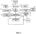
- FIG. 2 shows the flow of the switching controls system signals and power signals used to accomplish the needed signals to control motoring and/or braking of the aircraft landing gear wheel hub motor/generator within a brushless design.
- the Hall effect sensors 21 are used to indicate the position of the permanent magnets within the the rotor disk wherein the magnets are alternating north and south poles with the flux aligned axially and aligned with associated field coils.
- the position information of the rotor disk is sent to the processor 23 for proper timing of control signals which are sent to the optical isolators 25 which are then sent to the polyphase brushless commutation driver control 20 which applies power from the power storage device and/or onboard power supply 29 to the stator field coils within a single stator disk 32 such that a motor action is produced either in the forward or reverse directions dependent upon the input from the user brake and motoring input control 27 which provides information to the processor 23 through the optical isolators 25 such as to initiate user input for forward or reverse motor action within the wheel hub motor/generator and the input from the parking brake controller 24 to the processor 23 is such that it indicates whether the parking brake system is engaged or not.
- An alarm 22 will activate if the parking brake is engaged and user input from the user brake and motoring input control 27 is initiating motor action. If the parking brake is disengaged the processor 23 will allow motor action in the forward or reverse direction as per the user input from the user brake and motoring input control 27.
- an electrical power connection is provided for from the stator field coils within a single stator disk 32 to the regenerative braking and polyphase rectification control 31 and as the relative motion occurs between the stator and rotor sections a polyphase power signal is generated within the wheel hub motor/generator stator coils and this power signal is sent to the regenerative braking and polyphase rectification control 31 which converts the varying polyphase power signal into a DC signal based upon control signals generated from the processor 23 which is dependent upon the input user control signals from the user brake and motoring input control 27.
- the DC power signal is sent from the regenerative braking and polyphase control 31 to the power storage device and/or onboard power supply 29 for later use and/or sent to a power dissipation resistor 33 for the dissipation of the generated electrical power.
- the regenerative braking and polyphase rectification control 31 may also be used to provide polyphase electrical power to the motorized braking control 26 which is controlled by processor 23 control signals in applying motorized braking commands as described within the preferred embodiment wherein polyphase power signals are applied to stator field coils of other stator disk 28 within the same or other wheel hub motor/generator disk stack such as to supply electrical power to stator field coils of other stator disk 28 which are experiencing generator action thus increasing the braking effect by motoring the disk in the opposite direction to that of the rotor rotational direction thus providing for a motorized braking effect which is unique in the area of brushless axial flux motors and generators.
- Brushless axial flux motors and generators are well known in which the use of segmented rotor and stator sections are used. Variations of brushless axial flux motors and generators are taught within the following U.S. Patent. No. 4,223,255 , 4,567,391 4,585,085 , 6,046,518 , 6,064,135 6,323,573 B1 , 6,617,748 B2 and 6,633,106 B1 also within the following application publications US 2003/0159866 A1 and US 2002/0171324 A1 . Any axial flux type motor/generator also known as disk or pancake motors may be used incorporating the method of motorized braking as described within the patent including those which have yet to be issued patents.
- the rotors or stators are generally composed of permanent magnet segments such that there exist alternating north and south poles with the flux aligned axially.
- the rotor or stator sections generally consists of stator or rotor coils within a single stator or rotor disk attached to the stator or rotor disk with hall effect sensors which are also attached to the stator or rotor disk, which is also segmented as such to align the coil sets with that of the permanent magnets used within the rotor or stator.
- the stator or rotor coils within a single disk require controlled application of currents to said coils from a polyphase brushless commutation driver control such as to cause motor action.
- control signals applied to such polyphase brushless commutation driver controls are generated from a processor through optical isolation using position information provided for by the Hall effect sensors.
- Such brushless motors may also be used in regenerative braking to supply electrical current by means of generator action and the electrical current path is provided for by means of electrical switching controls wherein the electrical power generated is stored for later use via a control system.
- the windings may be either stationary or rotary in which the windings may be incorporated into the following structures.
- One such possible structure is a slotted laminated or composite iron core material with the windings located within slots.
- Another possible structure is a slotless structure in which the windings are wound into coils those are embedded within an ironless structure such as carbon or may be wound around a laminated or composite iron core material.
- a further possible structure is a solid structure in which induced currents circulate within a solid conducting material, which may or may not be a ferromagnetic material.
- Windings for a disk structure may be of printed circuit type and/or stamped from copper sheet and/or may be of copper windings wound into individual coils, which may or may not be of a litz wire construction.
- the instant after touch down the wheel hub motor/generator which is used as a motor may be converted so as to be used as a generator by discontinuing the application of power to the stator disk and drawing power from said stator disk due to the generator action that takes place when the magnetic field of the rotor disk is in relative motion with that of the stator disk such relative motion is due to the kinetic energy of the aircraft and by using well-known electrical switching action and controls such as electronically controlled switches such as IGBT's or IGCT's and/or electromechanical type relays such that generated electrical power may be stored as in regenerative braking and/or dissipated as in dynamic braking and/or applied to other stator disk which increases the braking effect by means of motorized braking.
- the generated electrical current from the stator disk may be stored on the airplane by means of battery, capacitor banks or other suitable electrical power storage devices such as a gyro and/or toroidal coil or coils that are electrically connected to the stator disk through the implementation of control electronics and/or physical contacts, thus allowing for dissipation and/or storage of electrical power generated for the purpose of supplying electrical power for later use.
- suitable electrical power storage devices such as a gyro and/or toroidal coil or coils that are electrically connected to the stator disk through the implementation of control electronics and/or physical contacts, thus allowing for dissipation and/or storage of electrical power generated for the purpose of supplying electrical power for later use.
- Electromagnetic braking in its motorized braking method is preferably applied by using associated rotor and stator disk or disks as a generator whose output is applied to another stator disk or disks which then produces a motor action which is in direct opposition to the rotational direction of the wheel which generates a motorized braking action that exceeds that of regenerative braking alone, thus decreasing the braking distance and increasing the safety of the aircraft.
- the method of motorized braking is preferably accomplished by two means.
- the first means is by the generated electrical power from one stator disk due to the relative motion of the associated rotor disk that may be applied to another stator disk within the wheel hub motor/generator disk stack in such a manner as to increase the braking effect by motoring the other associated rotor disk of said other stator disk in the opposite direction, thus accomplishing motorized braking or motoring of a disk or disks within the same or other wheel hub motor/generator disk stack as that of the generating disk or disks.
- the second means uses stored and/or onboard generated and/or external electrical power such that power is applied to the stator disk through provided electrical connections such that motor action is applied to the rotor disks in the opposite direction of rotation of the wheel thus accomplishing motorized braking or motoring of disk or disks within the wheel hub motor/generator.
- the two means above may be combined to produce the desired braking.
- the axial flux wheel hub motor/generator may be used to provide for motor action to the aircraft landing gear wheels thus providing a gyroscopic stabilization effect to the aircraft.
- the aircraft would deploy the landing gear and then apply a forward rotary motion to the aircraft landing gear wheels, which will stabilize the aircraft due to the gyroscopic effect thus increasing the stability and safety of the aircraft.
- Another embodiment uses eddy current braking as opposed to electromagnetic braking wherein the rotor disk are constructed of aluminum, aluminum alloy, steel, copper, beryllium, silver or any combination thereof of various constructions and the stator disk may be constructed as described above in the electromagnetic case of the previous preferred embodiment wherein the braking is accomplished by applying electrical current to the stator disk such that the magnetic field of the stator disk induces eddy currents within said rotor disk such that there is developed a magnetic torque which generates a braking action upon the wheel of said aircraft.
- any combination of the above embodiments may be used in addition to that of friction braking systems currently used, thus increasing the life and aiding the usefulness of the friction braking system as well as reducing the associated maintenance cost by reducing the rate of wear and the number of friction disk required. Cooling systems used for friction braking systems may also be employed in the above embodiments and embodiment combinations if needed.
- the pilot deploys the landing gear and the landing gear wheel hub motor/generator is applied power by the pilot input controls such as to cause a forward rotation of the landing gear tires.
- the rotational velocity of a landing gear tire for a 130-mile per hour landing event for a typical 747 aircraft would be approximately 48 rad/sec in order to match the tire and ground velocities thus greatly reducing the sliding friction wear of said tires.
- the instant after touchdown the control systems are used to store the generated electrical power from the wheel hub motor/generator thus providing regenerative braking. Then a few moments later the stored energy is applied to the wheel hub motors via the control system to cause motor action in the opposite direction than that of the rotational direction of the rotor thus providing for motorized braking.
- the pilot would initiate input controls such as to cause a forward rotation of the landing gear tires and power up the jet engines. This would cause the aircraft to travel down the runway faster than with the use of the jet engines alone thus reducing the needed runway distance for takeoff for a particular aircraft.
- the pilot would initiate input controls such as to cause one set of landing gear to be powered in the forward direction and the other set of landing gear to be powered in the opposite direction thus accomplishing the turning of said aircraft which is terminated under the control of the pilot.
- power supplied is from and external source of power via an attachment to the aircraft such as that used to propel or launch aircraft off an aircraft carrier.
- the means of electrical connection can be a direct physical contact connector or a non-contact type that employs the use of magnetic induction to transfer the energy from a ground track to the aircraft.
- ground tracks could be incorporated into the runways of an airport such as to allow for power transfer and/or provide for a means in which aircraft control personnel could directly control ground movements of aircraft by controlling the power supplied to the aircraft wheel hub motor/generator thus increasing the level of control for the aircraft control personnel.
- the system may be very flexible in control such as allowing one stator-rotor disk set to be able to supply another stator-rotor disk set such as to accomplish motorized braking.
- the motorized braking may be accomplished by applying a rotational torque in the opposite direction as that of the rotational motion due to the landing event
- the present invention need not utilize axial flux motors. Any electrical motor-generator device known in the art may be applied to the various landing gear assembly embodiments disclosed to achieve their corresponding benefits.
- the present invention includes other advantages. For example, where two or more wheels of a main landing gear may be rotated differentially and/or in opposite directions, the "turning radius" or width of runway needed by an aircraft to turn 180° decreases, thus making available smaller landing strips that otherwise would not be available to an aircraft. This in turn will allow aircrafts to take more direct travel paths, being able to rely on additional landing strips in case of emergency, thus reducing flight times and fuel consumption.
- stator-rotor sets to convert electrical energy (whether stored onboard in an electrical energy storage device or offboard and transferred via, e.g., induction) to rotational energy of the wheel may help to alleviate some of the inefficiencies of operating an aircraft's jet engines at low speeds.
- electrically operated wheels may also reduce or eliminate the need for tow motors which are conventionally used to move aircrafts in manners otherwise difficult (e.g., in reverse).
- the ability of the system to spin up the landing gear wheels to a speed that approximately matches the aircraft's speed upon landing reduces the "jolt" or impulse that typically results when the stationary wheels of conventional aircraft quickly and violently speed up upon the aircraft's touchdown. Reducing or eliminating this jolt has the advantages of added passenger comfort, reduced tire and landing strip wear, and may also provide a stabilizing gyroscopic effect.
- the motor action of the wheel hub motor/generator may be used as a source of motive power for the deployment or extension of the landing gear in preparation for a landing event or for retracting of the landing gear after take off, wherein the motor act is transmitted through a mechanical linkage to cause the positioning of and locking of the landing gear.
- Such a system may be implemented using a screw drive mechanism or other such mechanical means to provide for the transmission of movement from the wheel hub motor/generator to the movement of the landing gear struts or support assembly into a down and locked position in the case of a landing event and an up and secure position after a take off event
- the assembly may include both a nose gear and a main landing gear.
- the nose gear may have many or all of the same features as the main landing gear, such as one or more motor-generators (such as axial flux motor-generators), that may be controllable by a processor.
- the nose gear may comprise two or more wheels that may be rotated differentially, depending on a steering signal from a user and processed by the processor.
- Prior steering methods of aircraft are by either differential braking and/or turning the nose gear.
- Differential braking uses applied brakes to one side of the aircraft or the other as required to turn the aircraft along with an input from the pilot as to the nose gear direction by means of a hand wheel and/or rudder input.
- Differential braking causes severe ground or runway erosion and constant use can result in landing gear failure.
- Prior nose wheel steering angles are limited to plus or minus 60 degrees which is imposed by the available methods such as push-pull actuators, rack and pinion, rotary actuators, and multiplying linkage mechanical systems, which experience wear an require maintenance. Such mechanical actuators can cause movement of the nose gear while in flight if there is a failure of the self centering system.
- Rotating two or more wheels of the nose gear differentially provides for turning of the nose gear only when the tries are in physical contact with the ground or runway which provides the required torque to steer the wheels without any forward motion of the aircraft.
- This steering may be accomplished by means of motoring one nose wheel hub motor/generator in one direction and motoring the other nose wheel hub motor/generator in the other direction thus allowing for positioning of the nose gear in any position desired by the pilot through the input of the handwheel.
- the respective nose wheel hub motor/generators may be turned in the same direction at different speeds.
- This new steering method thus provides for an increase in maneuverability and a reduction in weight along with the added feature of increased reliability.
- both tires are rotating in the same direction and upon an input from the pilot from the handwheel one tire will, be caused to rotate faster than the other tire thus providing for a differential in input power to the wheel hub motor/generators thus allowing for steering of the nose gear in any desired direction while moving.
- Prior methods used in nose gear of aircraft generate uneven wear of the nose gear tires during the landing event thus creating an imbalance in the nose gear tires. This imbalance of the nose gear tires can generate a shimmy on the nose gear wheels.
- the performance of the nose gear steering system is increased due to the reduced shimmy which is due to the uneven wear of the nose gear tires upon a landing event thus providing for an increase in stability over current methods used.
- the nose gear which is often used to help in steering, may be more capable of steering where it is forced strongly against the landing strip, particularly immediately after touchdown, so the system could include a fin or spoiler, or the equivalent, configured to direct air upward to help increase the force of the nose gear and front of the aircraft toward the landing strip.
- the invention provides improved ABS braking.
- a significant advantage of an electromagnetic braking system is the fact that the feedback signal is a 1000 times faster that those within a hydraulic system thus allowing for an increase in effective braking capacity of an ABS thus increasing the level of safety and also contributes to an increased level of reliability as electromagnetic devices are inherently more reliable than hydraulic devices.
- the electromagnetic braking system is also inherently anti-locking.
- ABS Anti-lock Braking System
- any conventional ABS or improved ABS may be incorporated within the present invention so as to produce the desired braking of the aircraft.
- One such possible means will be described that implements the use of fuzzy logic as a possible control means.
- ABS is implemented to ensure optimal control and minimal stopping distances during hard or emergency braking.
- the number of aircraft equipped with ABS has been increasing continuously over the years and ABS is now accepted as an essential contribution to aircraft safety.
- the methods of control utilized by ABS are responsible for improved system performance, and improving ABS capability is a goal of aircraft manufacturers.
- ECUs Electronic control units
- wheel speed sensors transmit pulses to the ECU with a frequency proportional to wheel speed.
- the ECU then processes this information and regulates the brake accordingly.
- the ECU and a control algorithm are partially responsible for how well the ABS system performs which may implement a fuzzy logic control algorithm for use in an ABS system.
- ABS systems are nonlinear and dynamic in nature they are a prime candidate for fuzzy logic control.
- Wheel slip under these conditions is largely considered to be the difference between vehicle velocity and a reduction of wheel velocity during the application of braking force.
- Brakes work because friction acts against slip. The more slip given enough friction, the more braking force is brought to bear on the aircrafts momentum.
- slip can and will work against itself during a RTO or on wet or icy surfaces where the coefficient of surface friction varies. If braking force continues to be applied beyond the runway surface's useful coefficient of friction, the brake effectively begins to operate in a non-friction environment. Increasing brake force in a decreasing frictional environment often results in full wheel lockup. It has been both mathematically and empirically proven a sliding wheel produces less friction than the rolling friction of a moving wheel.
- ABS control algorithms should account for non-linearity in brake torque due to temperature variation and dynamics of the magnetic flux field interactions. Also, external disturbances such as changes in frictional coefficient and runway surface should be accounted for, not to mention the influences of tire wear and system components aging. These influential factors increase system complexity, in turn effecting mathematical models used to describe systems. As the model becomes increasingly complex equations required to control ABS also become increasingly complicated. Due to the highly dynamic nature of ABS many assumptions and initial conditions are used to make control achievable. Once control is achieved the system is implemented in prototype demonstration setups and tested. The system is then modified to attain the desired control status as defined by the test setup.
- FIG. 3 is a block diagram illustrating a method and apparatus for fuzzy logic ABS control in accordance with the invention.
- the Inputs to the Fuzzy logic ABS are represented in FIG. 3 and consist of:
- Acceleration and slip for each wheel may be calculated by combining the signals from each wheel. These signals are then processed in the Fuzzy logic ABS system to achieve the desired control and such architecture is such as to take advantage of improved math execution timing as such improvements are made available.
- Dynamic Braking When Dynamic Braking is active wherein Dynamic Braking consist of using the wheel hub motor/generator as a generator and applying the output power to a resistor bank it may be setup such that the braking system releases the Automatic Braking System on the wheel hub motor/generators, since both braking systems could result in too much resistance and cause the wheels to slide thus causing flat areas on the tires of the wheels.
- Another variation would be Blended braking. Blended braking is used to make braking even more efficient. Created by feedback Electronics of the ABS, blended braking will use some Automatic Braking Systems while in the lower range of Dynamics and at the higher Amperage of the Dynamics use the less Automatic Braking if used. In full Dynamics the Automatic Brake could be such as to be completely released. Blended braking is tied into the wheel slip and other braking control circuits such as acceleration rates and velocity on the wheel hub motor/generator.
Landscapes
- Engineering & Computer Science (AREA)
- Mechanical Engineering (AREA)
- Aviation & Aerospace Engineering (AREA)
- Transportation (AREA)
- Electromagnetism (AREA)
- Power Engineering (AREA)
- Physics & Mathematics (AREA)
- Electric Propulsion And Braking For Vehicles (AREA)
- Braking Arrangements (AREA)
- Arrangement Or Mounting Of Propulsion Units For Vehicles (AREA)
- Regulating Braking Force (AREA)
- Connection Of Motors, Electrical Generators, Mechanical Devices, And The Like (AREA)
- Tires In General (AREA)
Priority Applications (1)
| Application Number | Priority Date | Filing Date | Title |
|---|---|---|---|
| EP18156528.4A EP3342701A1 (en) | 2003-12-15 | 2004-12-15 | Method and apparatus for braking and maneuvering |
Applications Claiming Priority (2)
| Application Number | Priority Date | Filing Date | Title |
|---|---|---|---|
| US10/734,216 US7237748B2 (en) | 2003-12-15 | 2003-12-15 | Landing gear method and apparatus for braking and maneuvering |
| PCT/US2004/041843 WO2005102839A2 (en) | 2003-12-15 | 2004-12-15 | Method and apparatus for braking and maneuvering |
Related Child Applications (1)
| Application Number | Title | Priority Date | Filing Date |
|---|---|---|---|
| EP18156528.4A Division EP3342701A1 (en) | 2003-12-15 | 2004-12-15 | Method and apparatus for braking and maneuvering |
Publications (3)
| Publication Number | Publication Date |
|---|---|
| EP1704087A2 EP1704087A2 (en) | 2006-09-27 |
| EP1704087A4 EP1704087A4 (en) | 2008-08-13 |
| EP1704087B1 true EP1704087B1 (en) | 2018-02-14 |
Family
ID=35059586
Family Applications (2)
| Application Number | Title | Priority Date | Filing Date |
|---|---|---|---|
| EP04821791.3A Revoked EP1704087B1 (en) | 2003-12-15 | 2004-12-15 | Method and apparatus for braking and maneuvering |
| EP18156528.4A Withdrawn EP3342701A1 (en) | 2003-12-15 | 2004-12-15 | Method and apparatus for braking and maneuvering |
Family Applications After (1)
| Application Number | Title | Priority Date | Filing Date |
|---|---|---|---|
| EP18156528.4A Withdrawn EP3342701A1 (en) | 2003-12-15 | 2004-12-15 | Method and apparatus for braking and maneuvering |
Country Status (12)
Cited By (1)
| Publication number | Priority date | Publication date | Assignee | Title |
|---|---|---|---|---|
| EP3998204A1 (en) | 2021-02-19 | 2022-05-18 | Lilium eAircraft GmbH | Aircraft landing gear |
Families Citing this family (170)
| Publication number | Priority date | Publication date | Assignee | Title |
|---|---|---|---|---|
| US7234667B1 (en) * | 2003-12-11 | 2007-06-26 | Talmage Jr Robert N | Modular aerospace plane |
| GB2435697B (en) * | 2004-08-17 | 2009-09-09 | Borealis Tech Ltd | Aircraft drive |
| US7445178B2 (en) * | 2004-09-28 | 2008-11-04 | The Boeing Company | Powered nose aircraft wheel system |
| US20070084683A1 (en) * | 2005-02-10 | 2007-04-19 | Steers Jerome A | Wheel-based propulsion system for vehicles |
| JP2009515499A (ja) * | 2005-11-09 | 2009-04-09 | エヴァンズ エレクトリック ピーティワイ リミテッド | 車両の駆動システム |
| GB0523069D0 (en) | 2005-11-11 | 2005-12-21 | Airbus Uk Ltd | Aircraft braking system |
| US7594626B2 (en) | 2006-06-08 | 2009-09-29 | Rod F. Soderberg | Magnetically induced aircraft landing wheel rotation |
| US20070284939A1 (en) * | 2006-06-12 | 2007-12-13 | Honeywell International | Aircraft electric brake and generator therefor |
| GB0616985D0 (en) * | 2006-08-29 | 2006-10-04 | Borealis Tech Ltd | Transistor |
| US8700239B2 (en) * | 2007-01-16 | 2014-04-15 | Charles Hampton Perry | Machine for augmentation, storage, and conservation of vehicle motive energy |
| US20090072080A1 (en) * | 2007-03-08 | 2009-03-19 | Bhargava Brij B | On board secondary propulsion system for an aircraft |
| US8109464B2 (en) | 2007-03-08 | 2012-02-07 | The Ashman Group, Llc | Aircraft taxiing and secondary propulsion system |
| US20080217466A1 (en) * | 2007-03-08 | 2008-09-11 | Bhargava Brij B | Auxiliary on board power system for an aircraft |
| US7980509B2 (en) * | 2007-03-08 | 2011-07-19 | The Ashman Group, Llc | Aircraft taxiing systems |
| FR2913935B1 (fr) * | 2007-03-20 | 2009-05-15 | Airbus France Sas | Procede et dispositif de freinage aerodynamique a accumulation d'energie |
| US7818100B2 (en) * | 2007-04-03 | 2010-10-19 | The Boeing Company | System and method for optimized runway exiting |
| US8123163B2 (en) * | 2007-04-20 | 2012-02-28 | The Boeing Company | Aircraft kinetic landing energy conversion system |
| JP5004224B2 (ja) * | 2007-07-24 | 2012-08-22 | 独立行政法人 宇宙航空研究開発機構 | 短距離離着陸航空機 |
| GB0717903D0 (en) | 2007-09-14 | 2007-10-31 | Airbus Uk Ltd | Method and apparatus for providing power in an aircraft to one or more aircraft systems |
| US20090101754A1 (en) * | 2007-10-18 | 2009-04-23 | O'connell Charles | Aircraft nose gear control apparatus |
| FR2925017B1 (fr) * | 2007-12-13 | 2010-01-15 | Messier Bugatti | Procede d'alimentation en energie d'actionneurs associes a un train d'atterrissage d'aeronef |
| US8335600B2 (en) * | 2007-12-14 | 2012-12-18 | The Boeing Company | Regenerative integrated actuation system and associated method |
| DE102008006295B4 (de) * | 2008-01-28 | 2018-05-03 | Deutsches Zentrum für Luft- und Raumfahrt e.V. | Angetriebenes flugzeugfahrwerk |
| DE102008011791B4 (de) * | 2008-02-29 | 2013-09-19 | Airbus Operations Gmbh | Integriertes multifunktionales Radantriebssystem für Luftfahrzeuge |
| GB0806660D0 (en) * | 2008-04-11 | 2008-05-14 | Airbus Uk Ltd | Aircraft landing gear |
| GB2459714B (en) | 2008-05-02 | 2011-03-23 | Ge Aviat Uk | Aircraft landing gear steering system |
| FR2930760B1 (fr) * | 2008-05-05 | 2010-09-10 | Airbus France | Dispositif annexe de deplacement au sol d'un vehicule aerien a turbine a air |
| DE102008023698B4 (de) * | 2008-05-09 | 2010-09-23 | Jan Binnebesel | Bodengebundene Vorrichtung für den Start-, Lande- und Rollvorgang von Flugzeugen |
| US20090315493A1 (en) * | 2008-06-24 | 2009-12-24 | Hsia-Yuan Hsu | Single-phase brushless forward and reverse turn control circuit device |
| DE102008031933B4 (de) * | 2008-07-07 | 2011-04-28 | Airbus Operations Gmbh | Radantriebssystem für ein Flugzeug mit einer Brennstoffzelle als Energiequelle |
| GB2466436A (en) * | 2008-12-18 | 2010-06-23 | Scimar Engineering Ltd | Axial flux motor and generator assemblies |
| ATE549219T1 (de) * | 2009-01-28 | 2012-03-15 | Alenia Aeronautica Spa | Bremssystem für das fahrgestell eines flugzeugs |
| FR2944775B1 (fr) * | 2009-04-24 | 2013-03-08 | Messier Bugatti | Procede de deplacement d'un aeronef au sol |
| US8371520B2 (en) * | 2009-07-31 | 2013-02-12 | William Craig Easter | Rapidly convertible hybrid aircraft and manufacturing method |
| US8015830B2 (en) * | 2009-08-20 | 2011-09-13 | Hamilton Sundstrand Space Systems International, Inc. | Heat pump for high temperature environments |
| IT1395712B1 (it) * | 2009-09-10 | 2012-10-19 | Gaia | Dispositivo e metodo per una rotazione delle ruote dei carrelli di atterraggio di aeromobili |
| FR2953196B1 (fr) * | 2009-11-30 | 2011-12-09 | Messier Bugatti | Procede de gestion du freinage d'un aeronef et systeme de freinage correspondant |
| FR2954235B1 (fr) * | 2009-12-17 | 2012-03-16 | Michelin Soc Tech | Systeme de motorisation electrique d'une roue |
| FR2954283B1 (fr) * | 2009-12-23 | 2012-03-02 | Hispano Suiza Sa | Aeronef comportant un demarreur-generateur electrique pour le ou chaque turboreacteur et un train d'aterrissage equipe d'un moteur electrique de manoeuvre au sol |
| FR2954752B1 (fr) * | 2009-12-24 | 2012-03-09 | Messier Bugatti | Ensemble de roue et frein pour aeronef equipe d'un dispositif d'entrainement en rotation. |
| US20110168465A1 (en) * | 2010-01-14 | 2011-07-14 | Gary Starr | Hub wheel motor |
| IT1398207B1 (it) | 2010-02-16 | 2013-02-14 | Alenia Aeronautica Spa | Sistema frenante per carrello di velivolo. |
| US9085358B2 (en) * | 2010-03-17 | 2015-07-21 | Borealis Technical Limited | Electric motor integrated with a wheel |
| US9216819B2 (en) * | 2010-03-29 | 2015-12-22 | Borealis Technical Limited | Wheel structure for integrating an electric drive motor |
| US8714481B2 (en) * | 2010-04-08 | 2014-05-06 | Borealis Technical Limited | Integrated electric motor and gear in an aircraft wheel |
| FR2959483B1 (fr) * | 2010-04-28 | 2012-06-01 | Messier Bugatti | Procede de gestion d'une liaison au sol d'un aeronef. |
| US9428265B2 (en) | 2010-05-24 | 2016-08-30 | Borealis Technical Limited | Integrated vehicle wheel motor structured to manage heat |
| FR2960520B1 (fr) * | 2010-05-26 | 2012-06-29 | Airbus Operations Sas | Aeronef comprenant un moteur de train |
| US8853869B2 (en) * | 2010-08-31 | 2014-10-07 | Zivota Nikolic | Wheel-mounted electric generator |
| FR2965074B1 (fr) * | 2010-09-21 | 2012-08-31 | Messier Bugatti | Procede de gestion d'un mouvement au sol d'un aeronef. |
| US8403257B2 (en) * | 2010-12-03 | 2013-03-26 | Bae Systems Controls Inc. | Hydraulic ground propulsion system |
| FR2968483B1 (fr) * | 2010-12-06 | 2015-09-04 | Messier Bugatti | Procede de commande d'un moteur a courant continu sans balai. |
| FR2968274B1 (fr) * | 2010-12-06 | 2013-02-01 | Messier Bugatti | Dispositif de freinage/entrainement d'une roue d'aeronef. |
| WO2012106643A1 (en) * | 2011-02-04 | 2012-08-09 | Borealis Technical Limited | Method of operating aircraft drive move an aircraft under adverse ground conditions |
| GB2507412A (en) * | 2011-03-01 | 2014-04-30 | Borealis Tech Ltd | Method of reducing fuel carried by an aircraft in flight |
| US8764126B2 (en) * | 2011-05-03 | 2014-07-01 | Robert Bosch Gmbh | Fuzzy logic based brake control |
| US9511853B2 (en) | 2011-05-24 | 2016-12-06 | Borealis Technical Limited | Motor and gearing system for aircraft wheel |
| US8833694B2 (en) * | 2011-06-14 | 2014-09-16 | Neal Gilleran | Split circumference aircraft wheel assembly with integrated drive motor assembly |
| US20130112805A1 (en) * | 2011-07-06 | 2013-05-09 | Borealis Technical Limited | Method for reducing requirements for aircraft brake size, complexity, and heat dissipation |
| US9233752B2 (en) | 2011-07-29 | 2016-01-12 | Borealis Technical Limited | Drive system with harmonic drive for self-propelled aircraft wheel |
| US9193449B2 (en) | 2011-08-22 | 2015-11-24 | Borealis Technical Limited | Method for optimizing operation of aircraft ground travel drive system |
| DE102011082029A1 (de) * | 2011-09-01 | 2013-03-07 | Airbus Operations Gmbh | Vorrichtung zur rückgewinnung der bewegungsenergie, die beim landen eines flugzeugs nach erfolgter bodenberührung frei wird, sowie verfahren |
| US9013330B2 (en) | 2011-09-01 | 2015-04-21 | Honeywell International Inc. | Electric taxi system guidance |
| US9676475B2 (en) | 2011-09-02 | 2017-06-13 | Borealis Technical Limited | System and method for maintaining aircraft ground travel speed and direction |
| US9475574B2 (en) | 2011-09-14 | 2016-10-25 | Borealis Technical Limited | Heat dissipation system for aircraft drive wheel drive assembly |
| DE102011113952B4 (de) * | 2011-09-20 | 2023-06-15 | Liebherr-Aerospace Lindenberg Gmbh | Stellgerätesystem für Luftfahrzeuge |
| US8880427B1 (en) | 2011-11-28 | 2014-11-04 | iPourIt, Inc. | Beverage dispensing and tracking system |
| US10839715B2 (en) | 2012-01-06 | 2020-11-17 | Borealis Technical Limited | Training system and simulation method for ground travel in aircraft equipped with non-engine drive means |
| US9555884B2 (en) | 2012-02-16 | 2017-01-31 | Borealis Technical Limited | Method for improving ground travel capability and enhancing stealth in unmanned aerial vehicles |
| US9169025B2 (en) | 2012-02-27 | 2015-10-27 | Borealis Technical Limited | Method for inflight deicing of landing gear and wheel bays in aircraft with onboard drive means |
| US9315177B2 (en) * | 2012-03-14 | 2016-04-19 | Textron Innovations Inc. | Antilock braking system with directional control |
| US20130240665A1 (en) * | 2012-03-16 | 2013-09-19 | Borealis Technical Limited | Method for improving efficiency of airport deicing operations |
| US20130240664A1 (en) * | 2012-03-16 | 2013-09-19 | Borealis Technical Limited | Method for determining relational speed and position in an aircraft equipped with a landing gear drive wheel |
| US8899516B2 (en) | 2012-04-05 | 2014-12-02 | JHamilton Sundstrand Corporation | Coaxial contra-rotating motors for differential landing gear steering |
| US8973866B2 (en) | 2012-04-10 | 2015-03-10 | Hamilton Sundstrand Corporation | Transverse flux machine utilized as part of a combined landing gear system |
| US8620493B2 (en) | 2012-05-03 | 2013-12-31 | Honeywell International Inc. | Electric taxi auto-guidance and control system |
| US9067500B2 (en) | 2012-05-21 | 2015-06-30 | Krassimire Mihaylov Penev | Self rechargeable synergy drive for a motor vehicle |
| US8646550B2 (en) * | 2012-05-21 | 2014-02-11 | Krassimire Mihaylov Penev | Self rechargeable synergy drive for a motor vehicle |
| RO127819A0 (ro) * | 2012-05-31 | 2012-09-28 | Ovidiu Costache | Sistem automat de reglare a vitezei de rotaţie a roţilor aeronavelor la aterizare în scopul reducerii uzurii anvelopelor |
| US10179645B2 (en) * | 2012-07-25 | 2019-01-15 | Borealis Technical Limited | Surface travel system for military aircraft |
| GB2500442B (en) * | 2012-08-21 | 2014-03-12 | Messier Dowty Ltd | A brake assembly and a method of operating a brake assembly |
| US20150266566A1 (en) | 2012-09-24 | 2015-09-24 | Sergey Ivanovich Ivandaev | Method for driving landing gear wheels of an aircraft and landing gear apparatus |
| US9074891B2 (en) | 2012-10-18 | 2015-07-07 | Honeywell International Inc. | High integrity, surface guidance system for aircraft electric taxi |
| GB201220618D0 (en) * | 2012-11-16 | 2013-01-02 | Airbus Operations Ltd | Landing gear force and moment distributer |
| GB2511856B (en) * | 2013-03-15 | 2015-07-01 | Goodrich Actuation Systems Ltd | Damping arrangement for aircraft landing gear, for example a nosewheel |
| CN104058091A (zh) * | 2013-03-18 | 2014-09-24 | 北京科实医学图像技术研究所 | 飞机制动新方案 |
| GB201315012D0 (en) * | 2013-08-22 | 2013-10-02 | Airbus Uk Ltd | Aircraft autonomous pushback |
| DE102013020339B4 (de) | 2013-11-27 | 2024-09-05 | Malte SCHWARZE | Schleppverband, bestehend aus mindestens einem Luftfahrzeug mit erhöhter Leistungsfähigkeit und Betriebssicherheit |
| GB2520696A (en) | 2013-11-27 | 2015-06-03 | Airbus Operations Ltd | Aircraft electric braking system |
| GB2520693A (en) * | 2013-11-27 | 2015-06-03 | Airbus Operations Ltd | Aircraft electric braking system |
| US9567069B2 (en) | 2014-01-31 | 2017-02-14 | Borealis Technical Limited | Aircraft drive wheel drive system with torque coupling clutch assembly |
| FR3017367B1 (fr) * | 2014-02-10 | 2017-02-24 | Airbus Operations Sas | Aeronef comportant un train d'atterrissage dont une roue est pourvue d'un moteur electrique et un systeme de commande dudit moteur electrique |
| KR101527568B1 (ko) * | 2014-02-28 | 2015-06-11 | 김준엽 | 항공모함에서의 항공기 착륙 성능향상장치 |
| GB2524092B (en) * | 2014-03-14 | 2020-05-20 | Airbus Operations Ltd | Landing gear drive system and method |
| CN103847959B (zh) * | 2014-03-22 | 2016-07-13 | 中国科学院电工研究所 | 基于飞轮储能的飞机制动能量回收系统 |
| US9650130B2 (en) * | 2014-03-24 | 2017-05-16 | Mohammed Bouzmane | Electric hydraulic motor system for aircraft |
| FR3021936B1 (fr) * | 2014-06-06 | 2016-06-24 | Messier Bugatti Dowty | Procede de gestion du freinage d'une roue d'aeronef |
| CN104037976A (zh) * | 2014-06-20 | 2014-09-10 | 吴建国 | 一种电力驱动制动一体化装置 |
| US20150375854A1 (en) * | 2014-06-27 | 2015-12-31 | Honeywell International Inc. | Differential steering control of electric taxi landing gear |
| US9787101B2 (en) * | 2014-09-09 | 2017-10-10 | Honeywell International Inc. | Bidirectional conversion architecture with energy storage |
| FR3026718B1 (fr) * | 2014-10-03 | 2018-03-02 | Airbus Operations (S.A.S.) | Systeme de roulage d'un aeronef. |
| US10308352B2 (en) * | 2014-12-12 | 2019-06-04 | Borealis Technical Limited | Monitoring system for aircraft drive wheel system |
| US20180237130A1 (en) * | 2014-12-31 | 2018-08-23 | Mra Systems, Inc. | Aircraft using energy recovery systems |
| CN104608921B (zh) * | 2015-01-29 | 2017-12-12 | 广州铁路职业技术学院 | 飞机机轮及助降方法 |
| RU2581996C1 (ru) * | 2015-03-11 | 2016-04-20 | Федеральное государственное бюджетное образовательное учреждение высшего профессионального образования "Уфимский государственный авиационный технический университет" | Способ раскрутки-торможения колес шасси |
| DE102016105399A1 (de) * | 2015-03-30 | 2016-10-06 | Ford Global Technologies, Llc | System und verfahren zum steuern von rekuperationsbremsung in einem fahrzeug |
| GB2537860A (en) * | 2015-04-28 | 2016-11-02 | Airbus Operations Sas | Aircraft steering system |
| GB2538081B (en) * | 2015-05-06 | 2017-08-16 | Rolls Royce Plc | Apparatus and methods for controlling velocity of aircraft during landing roll-out and/or taxiing |
| RU2589527C9 (ru) * | 2015-05-07 | 2016-11-10 | Василий Васильевич Лещенко | Дисковый электромеханический тормоз самолета |
| RU2586098C9 (ru) * | 2015-05-18 | 2016-11-10 | Василий Васильевич Лещенко | Дисковый электромеханический тормоз самолета |
| RU2585682C9 (ru) * | 2015-05-29 | 2016-11-10 | Василий Васильевич Лещенко | Дисковый электромеханический тормоз самолета |
| RU2597427C9 (ru) * | 2015-07-03 | 2016-11-10 | Василий Васильевич Лещенко | Многодисковый электромеханический тормоз самолета |
| FR3038295B1 (fr) * | 2015-07-03 | 2017-08-25 | Messier Bugatti Dowty | Tiges d'atterrisseur pour aeronefs revetue d'alliage de zinc et de nickel |
| GB2540183A (en) * | 2015-07-08 | 2017-01-11 | Airbus Operations Ltd | Braking control system for an aircraft |
| FR3040041B1 (fr) * | 2015-08-10 | 2017-08-25 | Messier Bugatti Dowty | Atterrisseur d'aeronef muni d'une commande d'orientation des roues du type a pignon-cremailliere. |
| US10272992B2 (en) | 2015-10-31 | 2019-04-30 | Borealis Technical Limited | Clutch assembly for aircraft drive wheel drive system |
| RU2612554C1 (ru) * | 2015-11-23 | 2017-03-09 | Василий Васильевич Лещенко | Многодисковый цилиндрический электромеханический тормоз самолета |
| RU2612458C1 (ru) * | 2015-11-24 | 2017-03-09 | Василий Васильевич Лещенко | Многодисковый электромеханический тормоз самолета |
| JP6626328B2 (ja) * | 2015-12-02 | 2019-12-25 | 株式会社Ihi | 航空機の電動タキシングシステム |
| RU2612553C1 (ru) * | 2015-12-11 | 2017-03-09 | Василий Васильевич Лещенко | Многодисковый цилиндрический электромеханический тормоз самолета |
| GB2545706A (en) | 2015-12-22 | 2017-06-28 | Airbus Operations Ltd | Aircraft landing gear |
| GB2532650B (en) * | 2016-02-18 | 2017-08-16 | Smith Neil | Multi dimensional layered pulse hub motor |
| CN106477030B (zh) * | 2016-10-17 | 2018-06-15 | 济南大学 | 散热电力制动装置的应用 |
| CN106394257B (zh) * | 2016-10-17 | 2018-12-21 | 济南大学 | 耦合式液压传动的节能蓄电装置的应用 |
| CN106394255B (zh) * | 2016-10-17 | 2018-08-17 | 济南大学 | 散热电力制动装置 |
| CN106516091B (zh) * | 2016-10-18 | 2018-07-20 | 济南大学 | 风水混合电阻制动器的应用 |
| CN106394878B (zh) * | 2016-10-18 | 2018-06-08 | 济南大学 | 风水混合电阻制动器 |
| GB2555834A (en) * | 2016-11-11 | 2018-05-16 | Airbus Operations Ltd | Braking energy dissipation |
| CN107357324B (zh) * | 2017-06-11 | 2019-11-29 | 珠海磐磊智能科技有限公司 | 控制力矩陀螺、控制力矩陀螺仪及行驶装置 |
| US10543909B2 (en) * | 2017-09-11 | 2020-01-28 | Goodrich Corporation | System and method for aircraft electric taxi brake optimization |
| GB2566499B (en) * | 2017-09-15 | 2019-12-18 | De Innovation Lab Ltd | Regenerative braking arrangement for electrical vehicles |
| RU2667411C1 (ru) * | 2017-11-27 | 2018-09-19 | Сергей Анатольевич Костин | Способ формирования вспомогательных управляющих сигналов на пробеге самолета |
| WO2019204455A1 (en) * | 2018-04-19 | 2019-10-24 | Inductive Ventures Llc | Combination brake-generator inverted motor |
| EP3560826B1 (en) | 2018-04-25 | 2022-11-30 | Safran Landing Systems UK Ltd | Noise reduction fairing |
| CN108639315A (zh) * | 2018-07-06 | 2018-10-12 | 安徽思源三轻智能制造有限公司 | 飞机起落架 |
| US10862408B2 (en) | 2018-07-12 | 2020-12-08 | Parker-Hannifin Corporation | Electric motor regenerated energy management method |
| RU2684961C1 (ru) * | 2018-07-18 | 2019-04-16 | Сергей Анатольевич Костин | Способ формирования вспомогательных управляющих сигналов на пробеге самолета |
| DE102018221789A1 (de) * | 2018-12-14 | 2020-06-18 | Robert Bosch Gmbh | Verfahren zum Bremsen eines Flugzeugs |
| US11674555B2 (en) | 2019-03-22 | 2023-06-13 | Aeroflux Braking Systems Inc. | Axially or radially actuated eddy current brake with integrated friction brake |
| GB2583706A (en) | 2019-04-23 | 2020-11-11 | Airbus Operations Ltd | Aircraft braking system |
| CN110239706A (zh) * | 2019-07-08 | 2019-09-17 | 张朝林 | 一种移动式飞机起飞降落方法及移动式飞机起落架 |
| US11479107B2 (en) | 2019-09-30 | 2022-10-25 | Toyota Motor Engineering & Manufacturing North America, Inc. | Selectively attachable and detachable axial hub motor |
| US11453296B2 (en) | 2019-09-30 | 2022-09-27 | Toyota Motor Engineering & Manufacturing North America, Inc. | Systems and methods for improving propulsion of a vehicle using selectively attachable hub motors |
| US11529862B2 (en) | 2019-09-30 | 2022-12-20 | Toyota Motor Engineering & Manufacturing North America, Inc. | Systems and methods for improving propulsion of a vehicle using selectively attachable hub motors and rotatable axles |
| GB2589299A (en) * | 2019-10-02 | 2021-06-02 | Advanced Mobility Res And Development Ltd | Systems and methods for aircraft |
| US11390380B2 (en) * | 2019-10-10 | 2022-07-19 | The Boeing Company | System and method for alleviating structural loads on a pivoting main landing gear of an aircraft in a pivot turn maneuver |
| US11557988B2 (en) * | 2020-01-28 | 2023-01-17 | Goodrich Corporation | Hybrid regeneration brake system |
| CN111196354B (zh) * | 2020-02-07 | 2021-09-28 | 北京保力马测控技术有限公司 | 一种用于飞机起落架磁流变减摆器的控制方法 |
| US11472539B2 (en) * | 2020-03-05 | 2022-10-18 | Goodrich Corporation | Distributed landing gear system architecture for electromechanical actuation |
| US11320010B2 (en) | 2020-04-02 | 2022-05-03 | Honeywell International Inc. | Braking system |
| CN111976961A (zh) * | 2020-07-08 | 2020-11-24 | 西安航空制动科技有限公司 | 一种6轮车架主起落架飞机刹车控制系统及方法 |
| US11710201B2 (en) | 2020-11-12 | 2023-07-25 | Une Llc | Method and system for allocation of liquid product from a virtual bottle |
| CN112477608A (zh) * | 2020-12-19 | 2021-03-12 | 陕西航空电气有限责任公司 | 一种航空电驱动系统用能量回馈装置及控制方法 |
| EP3998203A1 (en) | 2021-02-19 | 2022-05-18 | Lilium eAircraft GmbH | Aircraft landing gear assembly and aircraft |
| GB2605176A (en) * | 2021-03-25 | 2022-09-28 | Airbus Operations Ltd | Brake control system |
| US12057737B2 (en) | 2021-06-17 | 2024-08-06 | Aeroflux Braking Systems Inc. | Hybrid permanent magnet—electromagnet magnetic flux device |
| CN116639242A (zh) * | 2022-02-16 | 2023-08-25 | 中国航发商用航空发动机有限责任公司 | 起落架系统及飞行器的机动和制动方法 |
| CN114408166B (zh) * | 2022-02-22 | 2024-04-30 | 中国商用飞机有限责任公司 | 飞行器轮子驱动装置、轮子速度控制系统及控制方法 |
| FR3133164B1 (fr) | 2022-03-02 | 2024-03-15 | Safran Landing Systems | Dispositif de roulage à freinage magnétique à flux radial et axial combinés, et aéronef ainsi équipé |
| FR3133165B1 (fr) * | 2022-03-02 | 2024-05-31 | Safran Landing Systems | Dispositif de roulage à freinage mixte friction/magnétique, et aéronef ainsi équipé |
| US11851168B2 (en) * | 2022-03-18 | 2023-12-26 | Electra Aero, Inc. | System and method to minimize an aircraft ground turn radius |
| GB2617326A (en) * | 2022-03-31 | 2023-10-11 | Airbus Operations Ltd | Aircraft nose landing gear assembly |
| US11702193B1 (en) | 2022-04-28 | 2023-07-18 | Beta Air, Llc | Systems and methods for an electric vertical takeoff and landing aircraft braking system |
| US12149134B2 (en) | 2022-06-27 | 2024-11-19 | Anthropocene Institute LLC | Axial flux switched reluctance motor and generator, and related systems and methods |
| US12095320B2 (en) | 2022-06-27 | 2024-09-17 | Anthropocene Institute LLC | Axial flux switched reluctance and inductance state machine systems, devices, and methods |
| GB2626922B (en) * | 2023-01-31 | 2025-05-14 | Airbus Operations Ltd | Determining aircraft steering angle |
| FR3147555A1 (fr) * | 2023-04-07 | 2024-10-11 | Safran Landing Systems | Roue à dispositif de freinage magnétique pour véhicule, atterrisseur d’aéronef et aéronef équipés d’une telle roue |
| FR3148005B1 (fr) * | 2023-04-20 | 2025-03-28 | Safran Landing Systems | Dispositif de freinage magnétique à courant de Foucault, roue freinée de véhicule et atterrisseur d’aéronef, aéronef équipés d’une telle roue |
| KR20250014204A (ko) * | 2023-07-19 | 2025-02-03 | 현대자동차주식회사 | 항공기의 착륙장치 및 이를 이용한 이착륙 방법 |
| CN117446157A (zh) * | 2023-11-16 | 2024-01-26 | 贵州新安航空机械有限责任公司 | 一种直升机尾轮锁 |
Citations (41)
| Publication number | Priority date | Publication date | Assignee | Title |
|---|---|---|---|---|
| GB539405A (en) | 1939-04-25 | 1941-09-09 | Pierre Ernest Mercier | Improvements in or relating to aeroplane landing gears having a steerable landing wheel |
| US2391952A (en) * | 1943-06-15 | 1946-01-01 | Otto E Dever | Electric motor driven landing wheel for airplanes |
| US2408163A (en) | 1945-01-30 | 1946-09-24 | Technical Securitles Corp | Landing wheel drive |
| US2430163A (en) | 1944-09-25 | 1947-11-04 | Otto E Dever | Motor wheel |
| US2460387A (en) | 1943-12-03 | 1949-02-01 | Goodrich Co B F | Landing gear |
| US2463121A (en) | 1945-08-21 | 1949-03-01 | Goodrich Co B F | Vehicle wheel assembly and mounting |
| GB713626A (en) | 1949-02-11 | 1954-08-11 | Electro Hydraulics Ltd | Improvements in steering means for aircraft landing gear |
| US2687857A (en) | 1950-06-12 | 1954-08-31 | Electro Hydraulics Ltd | Steering means for aircraft landing gear |
| US2869662A (en) | 1956-02-14 | 1959-01-20 | Alfred L Koup | Detachable wheel assembly drive unit |
| US2993549A (en) | 1959-05-11 | 1961-07-25 | Cons Diesel Electric Corp | Ground power system for jet type aircraft |
| GB902155A (en) * | 1961-01-19 | 1962-07-25 | Brevets Aero Mecaniques | Improvements in and relating to electro-magnetic brakes |
| US3059712A (en) | 1961-11-13 | 1962-10-23 | Charles F Hautau | Aircraft wheel powering device |
| US3279222A (en) | 1963-04-22 | 1966-10-18 | Aladdin Ind Ltd | Liquid fuel burner font with automatic feed cut-off |
| DE1273335B (de) * | 1967-01-05 | 1968-07-18 | Lloyd Dynamowerke G M B H | Antrieb fuer ein Flugzeug-Fahrwerksrad |
| US3482806A (en) | 1967-01-05 | 1969-12-09 | Licentia Gmbh | Aircraft landing gear wheel |
| US3807664A (en) | 1971-09-21 | 1974-04-30 | Nace B | Self-contained aircraft taxiing system |
| US3850389A (en) | 1973-05-04 | 1974-11-26 | D Dixon | Landing gear wheel device for aircraft |
| US3977631A (en) | 1975-06-04 | 1976-08-31 | The Boeing Company | Aircraft wheel drive apparatus and method |
| US4001617A (en) * | 1974-06-07 | 1977-01-04 | Agence Nationale De Valorisation De La Rechereche (Anvar) | Rotary electrical machines comprising a superconductive winding |
| US4223255A (en) * | 1977-10-28 | 1980-09-16 | Goldman Gary S | Electric wheel |
| US4567391A (en) * | 1982-08-20 | 1986-01-28 | Octa, Inc. | Permanent magnet disc rotor machine |
| US4585085A (en) * | 1981-08-20 | 1986-04-29 | Handel Peter H | Electric wheel-drive for motor vehicles, in particular for nondestructive hybridization of automobiles |
| EP0046997B1 (de) | 1980-08-29 | 1987-06-24 | Peter Herwig Dr. Handel | Elektrischer Radantrieb für Kraftfahrzeuge, insbesondere für Hybrid-Personenkraftwagen |
| EP0611675A1 (fr) * | 1993-02-15 | 1994-08-24 | SMH Management Services AG | Véhicule automobile à traction électrique comprenant un dispositif de récupération d'énergie |
| WO1995029094A1 (en) * | 1994-04-22 | 1995-11-02 | Greenlite Limited | Aircraft landing-gear drive system |
| WO1996021965A1 (en) | 1995-01-12 | 1996-07-18 | Universita' Degli Studi Di Roma 'la Sapienza' | An axial flux electric machine, adapted for use as an electric propulsor for vehicles and as an electric power generator |
| WO1996038903A1 (en) * | 1995-05-30 | 1996-12-05 | Toeroek Vilmos | A self-starting brushless electric motor |
| US5721473A (en) | 1996-04-18 | 1998-02-24 | Devries; Leroy Milo | Electric motorized vehicular wheel with adjuncts |
| WO1998019875A1 (en) | 1996-11-05 | 1998-05-14 | Vernon Joel Grant | A modular wheel assembly |
| EP0875430A2 (en) * | 1997-05-02 | 1998-11-04 | Hydro-Aire, Inc. | System and method for adaptive brake application and initial skid detection |
| EP0921621A2 (en) * | 1993-06-14 | 1999-06-09 | Ecoair Corporation | Hybrid alternator with voltage regulator |
| US6046518A (en) * | 1999-01-21 | 2000-04-04 | Williams; Malcolm R. | Axial gap electrical machine |
| US6064135A (en) * | 1998-04-07 | 2000-05-16 | David H. Rush | Electromechanical machine and armature structure therefor |
| WO2000032462A1 (en) | 1998-11-30 | 2000-06-08 | Vernon Joel Grant | A modular wheel and/or conventional wheel assembly and control system |
| US6323573B1 (en) * | 1998-05-11 | 2001-11-27 | Active Power, Inc. | High-efficiency inductor-alternator |
| US6362750B1 (en) * | 1997-10-06 | 2002-03-26 | Siemens Ag | Process and device for automatically supported guidance of aircraft to a parking position |
| US6450448B1 (en) * | 2001-08-17 | 2002-09-17 | Toshimi Suzuki | Airplane wheel unit |
| US20020171324A1 (en) * | 1996-12-11 | 2002-11-21 | Smith Stephen H. | Axial field electric machine |
| US20030159866A1 (en) * | 2001-12-07 | 2003-08-28 | Claypole George M. | Wheel motor system |
| US6617748B2 (en) * | 1998-12-22 | 2003-09-09 | Rush Holdings Inc | Machine with cup-shaped armature and air gap |
| US6633106B1 (en) * | 1999-09-30 | 2003-10-14 | Dwight W. Swett | Axial gap motor-generator for high speed operation |
Family Cites Families (106)
| Publication number | Priority date | Publication date | Assignee | Title |
|---|---|---|---|---|
| WO1993023266A1 (en) | 1992-05-12 | 1993-11-25 | Seiko Epson Corporation | Electric car |
| US1622145A (en) * | 1923-12-12 | 1927-03-22 | Gen Motors Res Corp | Generator-regulating apparatus |
| US1931282A (en) * | 1932-03-12 | 1933-10-17 | Boykow Johann Maria | Automatic steering device |
| US2128044A (en) * | 1935-10-26 | 1938-08-23 | Westinghouse Electric & Mfg Co | Dynamo-electric machine |
| US2149634A (en) * | 1936-09-10 | 1939-03-07 | Jr Edmund O Schweitzer | Transformer fault indicating means |
| US2475461A (en) * | 1945-02-12 | 1949-07-05 | Lear Inc | Electric remote-control system |
| US2564320A (en) * | 1948-12-17 | 1951-08-14 | Keefe And Merritt Company O | Permanent magnet type electric generator |
| US2767368A (en) * | 1950-12-21 | 1956-10-16 | Kober William | Dynamoelectric control |
| US2914359A (en) * | 1955-12-01 | 1959-11-24 | Gordon W Yarber | Anti-skid brake control system |
| US2891742A (en) * | 1956-05-29 | 1959-06-23 | Sperry Rand Corp | Flight control system for aircraft |
| US3017145A (en) * | 1958-09-04 | 1962-01-16 | Gordon W Yarber | Control system for vehicle wheel brake |
| US2998538A (en) * | 1959-03-06 | 1961-08-29 | Sarl Auxilec | Continuously variable speed drive system |
| US3292021A (en) * | 1963-04-22 | 1966-12-13 | Avco Corp | Superconductive device |
| US3310976A (en) * | 1963-10-17 | 1967-03-28 | Bussell Bertram | Aircraft weight and center of gravity apparatus |
| US3344325A (en) * | 1965-05-04 | 1967-09-26 | Honeywell Inc | Step motor including permanent magnet rotor and sectioned stator |
| US3396325A (en) * | 1965-07-21 | 1968-08-06 | Ralph E. Hopkins | Voltage control of permanent magnet generators |
| US3622977A (en) * | 1968-03-30 | 1971-11-23 | Hisato Wakamatsu | Slip warning system for automotive vehicles |
| US3466518A (en) * | 1968-04-24 | 1969-09-09 | Ncr Co | Rotary stepping motors and control systems therefor |
| US3671788A (en) * | 1970-11-30 | 1972-06-20 | Gen Lab Associates Inc | Regulatable alternator |
| US4542809A (en) | 1979-07-30 | 1985-09-24 | Goodyear Aerospace Corporation | Electrically actuated aircraft brakes |
| US4432440A (en) | 1979-07-30 | 1984-02-21 | Goodyear Aerospace Corporation | Electrically actuated aircraft brakes |
| US4381049A (en) | 1979-07-30 | 1983-04-26 | Goodyear Aerospace Corporation | Electrically actuated aircraft brakes |
| US4567967A (en) | 1979-07-30 | 1986-02-04 | Goodyear Aerospace Corporation | Electrically actuated aircraft brakes |
| US4488053A (en) * | 1981-02-17 | 1984-12-11 | Lockheed Corporation | Electric constant speed/variable speed drive/generator assembly |
| JPS57146164A (en) * | 1981-03-05 | 1982-09-09 | Secoh Giken Inc | Speed detecting device for disk type motor |
| FR2522602A1 (fr) * | 1982-03-05 | 1983-09-09 | Messier Hispano Sa | Dispositif pour la commande d'un systeme de freinage de vehicule notamment d'un aeronef |
| JPS59181956A (ja) * | 1983-03-31 | 1984-10-16 | Oopack Kk | 無刷子直流回転電機 |
| WO1984004505A1 (en) * | 1983-05-12 | 1984-11-22 | Graham Roger Sinclair | Aircraft undercarriage assemblies |
| US4562399A (en) * | 1983-06-14 | 1985-12-31 | Kollmorgen Technologies Corporation | Brushless DC tachometer |
| US4596316A (en) | 1984-02-10 | 1986-06-24 | Goodyear Aerospace Corporation | Electrically actuated aircraft brakes |
| US4642539A (en) * | 1985-06-10 | 1987-02-10 | Northern Magnetics, Inc. | Torque motor with unlimited angular excursion |
| US4687158A (en) * | 1985-07-15 | 1987-08-18 | Lockheed Corporation | Jump strut landing gear apparatus and system |
| JPS62265023A (ja) * | 1986-05-12 | 1987-11-17 | Isuzu Motors Ltd | 車輪駆動装置 |
| US4865162A (en) | 1986-12-15 | 1989-09-12 | Opus Acquisition Corporation | Electrically actuated aircraft brakes |
| US6398162B1 (en) * | 1988-02-16 | 2002-06-04 | Dunlop Limited | Aircraft braking systems |
| US4885526A (en) * | 1988-03-18 | 1989-12-05 | Electro Erg Limited | Compensation circuit for electrical generators |
| JPH02246898A (ja) * | 1989-03-17 | 1990-10-02 | Nippo Sangyo Kk | 飛行機の着陸方法 |
| US5182958A (en) * | 1989-11-04 | 1993-02-02 | Black James W | Non-linear propulsion and energy conversion system |
| US6604708B1 (en) * | 1989-12-26 | 2003-08-12 | The Boeing Company | Carbon brake wear for aircraft |
| JPH03295796A (ja) * | 1990-04-16 | 1991-12-26 | Mitsubishi Heavy Ind Ltd | 飛行機用着陸装置 |
| US5104063A (en) * | 1990-04-27 | 1992-04-14 | Hartley James M | Aircraft landing gear prerotation system |
| US5205382A (en) * | 1990-10-09 | 1993-04-27 | The B. F. Goodrich Company | Aircraft brake |
| JP3052090B2 (ja) * | 1990-11-28 | 2000-06-12 | 利臣 鈴木 | 航空機の降着装置及び制御システム |
| US5097140A (en) * | 1991-05-07 | 1992-03-17 | Chrysler Corporation | Alternator starter |
| US5175462A (en) * | 1991-08-30 | 1992-12-29 | Fuji Xerox Co., Ltd. | Toroidal coil motor |
| US5207304A (en) * | 1991-12-03 | 1993-05-04 | The Regents Of The University Of California | Inductive energization system and method for vehicles |
| RU2023630C1 (ru) * | 1992-06-30 | 1994-11-30 | Белла Николаевна Комарова | Система автоматического управления курсовым положением самолета |
| US5397975A (en) * | 1993-06-14 | 1995-03-14 | Ecoair Corp. | Hybrid alternator |
| GB9320661D0 (en) * | 1993-10-07 | 1993-11-24 | Lucas Ind Public Limited | Electric vehicle having abs |
| US5669470A (en) * | 1994-05-05 | 1997-09-23 | H. R. Ross Industries, Inc. | Roadway-powered electric vehicle system |
| US5705917A (en) * | 1994-09-14 | 1998-01-06 | Coleman Powermate, Inc. | Light weight machine with rotor employing permanent magnets and consequence poles |
| JP3515628B2 (ja) * | 1995-04-14 | 2004-04-05 | 株式会社明電舎 | 電気自動車の駆動機構 |
| EP0743213B1 (en) * | 1995-05-19 | 2001-10-10 | Toyota Jidosha Kabushiki Kaisha | Hybrid vehicle power output apparatus and method of controlling the same in reverse drive |
| JP3687804B2 (ja) * | 1995-12-22 | 2005-08-24 | 日立金属株式会社 | 回転機用磁石回転子 |
| EP0798844A1 (en) * | 1996-03-28 | 1997-10-01 | Tai-Her Yang | The combined power driven device having a three-layered electromechanical structure with common structures |
| GB9612231D0 (en) * | 1996-06-12 | 1996-08-14 | Harris Michael A | Variable transmission apparatus |
| US5944147A (en) * | 1996-06-28 | 1999-08-31 | Alliedsignal Inc. | Integrated aircraft wheel, brake and axle |
| US6220676B1 (en) * | 1997-05-09 | 2001-04-24 | The B. F. Goodrich Company | Antiskid control of multi-wheel vehicles using coupled and decoupled Kalman filtering incorporating pitch weight transfer |
| JP3767103B2 (ja) * | 1997-07-16 | 2006-04-19 | 日産自動車株式会社 | 電気自動車の制御装置 |
| JP3096447B2 (ja) * | 1997-09-17 | 2000-10-10 | 本田技研工業株式会社 | ハイブリッド車両の制御装置 |
| JPH11196558A (ja) * | 1997-10-28 | 1999-07-21 | Fumio Uchiyama | 回転電機のステータコイル |
| JP3410022B2 (ja) * | 1998-05-20 | 2003-05-26 | 本田技研工業株式会社 | ハイブリッド車両の制御装置 |
| RU2143381C1 (ru) * | 1998-07-15 | 1999-12-27 | Открытое акционерное общество Авиационная корпорация "Рубин" | Многодисковый тормоз |
| WO2000005094A1 (fr) * | 1998-07-21 | 2000-02-03 | Tokyo R & D Co., Ltd. | Vehicule hybride et procede de gestion du deplacement du vehicule |
| GB9817757D0 (en) * | 1998-08-15 | 1998-10-14 | Dunlop Ltd | Breaking system |
| JP3622529B2 (ja) * | 1998-09-11 | 2005-02-23 | トヨタ自動車株式会社 | 動力出力装置、およびそれを搭載したハイブリッド車両並びに原動機の動作点制御方法 |
| JP3525218B2 (ja) * | 1998-09-18 | 2004-05-10 | 本田技研工業株式会社 | ハイブリッド車両の回生制御装置 |
| US6766874B2 (en) * | 1998-09-29 | 2004-07-27 | Hitachi, Ltd. | System for driving hybrid vehicle, method thereof and electric power supply system therefor |
| US6406102B1 (en) * | 1999-02-24 | 2002-06-18 | Orscheln Management Co. | Electrically operated parking brake control system |
| NO311200B1 (no) * | 1999-05-25 | 2001-10-22 | Smart Motor As | Elektrisk maskin |
| US6402259B2 (en) * | 1999-07-14 | 2002-06-11 | Goodrich Corporation | Electromechanical braking system with power distribution and redundancy |
| US6885920B2 (en) * | 1999-07-30 | 2005-04-26 | Oshkosh Truck Corporation | Control system and method for electric vehicle |
| DE60026335T2 (de) | 1999-09-13 | 2006-12-07 | Goodrich Corp. | Einheit von flugzeugrad, bremse und achse für ein rein elektrisches flugzeugbremssystem |
| EP1102385B1 (en) * | 1999-11-18 | 2006-05-10 | Denso Corporation | Rotary electric machine for vehicle |
| JP2001238303A (ja) * | 2000-02-24 | 2001-08-31 | Mitsubishi Motors Corp | ハイブリッド電気自動車の回生制御装置 |
| US6493618B2 (en) * | 2000-03-15 | 2002-12-10 | Toyota Jidosha Kabushiki Kaisha | Vehicle control using multiple sensors |
| JP3366899B2 (ja) * | 2000-06-13 | 2003-01-14 | 東海旅客鉄道株式会社 | 回生ブレーキ |
| RU2213408C2 (ru) * | 2000-06-26 | 2003-09-27 | Общество с ограниченной ответственностью Научно-Производственное Предприятие "ТЕХНОКРАТ" | Торцевой наборный электромотор |
| US6573675B2 (en) * | 2000-12-27 | 2003-06-03 | Transportation Techniques Llc | Method and apparatus for adaptive energy control of hybrid electric vehicle propulsion |
| WO2002083446A1 (fr) * | 2001-04-16 | 2002-10-24 | Kabushiki Kaisha Bridgestone | Procede pour fixer un moteur de type integre dans la roue et systeme de moteur de type integre dans la roue |
| US6659400B2 (en) * | 2001-05-23 | 2003-12-09 | Hydro-Aire, Inc. | Optimal control design for aircraft antiskid brake control systems |
| US6910844B2 (en) * | 2001-07-01 | 2005-06-28 | William B. Trescott | Self-loading vehicle for shipping containers |
| US6484072B1 (en) * | 2001-09-28 | 2002-11-19 | The United States Of America As Represented By The Secretary Of The Navy | Embedded terrain awareness warning system for aircraft |
| JP3712652B2 (ja) * | 2001-09-28 | 2005-11-02 | ジヤトコ株式会社 | パラレルハイブリッド車両 |
| ES2682997T3 (es) * | 2001-11-29 | 2018-09-24 | Yamaha Hatsudoki Kabushiki Kaisha | Máquina dinamoeléctrica de tipo de espacio axial |
| JP2003189409A (ja) * | 2001-12-21 | 2003-07-04 | Toyota Motor Corp | 電動機搭載車両 |
| JP3616847B2 (ja) * | 2001-12-25 | 2005-02-02 | 川崎重工業株式会社 | 陸上移動体の回生制動装置 |
| PT1490952E (pt) * | 2002-03-29 | 2008-12-30 | Matra Mfg & Services Sas | Motor eléctrico tendo grupos de estatores e rotores magneticamente isolados |
| JP2003300420A (ja) * | 2002-04-10 | 2003-10-21 | Hiroshi Shimizu | 電気自動車のインホイールモータ |
| JP4078879B2 (ja) * | 2002-05-23 | 2008-04-23 | 村田機械株式会社 | トラバース制御装置 |
| AU2003263769A1 (en) * | 2002-07-01 | 2004-01-19 | Xidem, Inc. | Electronically controlled electric motor |
| US20040263099A1 (en) * | 2002-07-31 | 2004-12-30 | Maslov Boris A | Electric propulsion system |
| US20040040756A1 (en) * | 2002-09-03 | 2004-03-04 | Abdulareef Nmngani | Gyroscopically stabilized vehicle |
| JP4151384B2 (ja) * | 2002-11-07 | 2008-09-17 | 日産自動車株式会社 | 燃料電池システム |
| FR2850926B1 (fr) * | 2003-02-07 | 2007-03-16 | Messier Bugatti | Frein electromecanique a dispositif de parc |
| US20040155468A1 (en) * | 2003-02-12 | 2004-08-12 | Tai-Her Yang | Series and parallel combined dual power drive system |
| JP2004248432A (ja) * | 2003-02-14 | 2004-09-02 | Toyota Motor Corp | 駆動装置およびこれを備える自動車 |
| US7411371B2 (en) * | 2003-02-28 | 2008-08-12 | Arizona Public Service Company | Battery charger and method of charging a battery |
| US6758440B1 (en) * | 2003-03-21 | 2004-07-06 | Curtiss-Wright Electro-Mechanical Corporation | Electromagnetic aircraft arrestor system |
| US20040212259A1 (en) * | 2003-04-24 | 2004-10-28 | Gould Len Charles | Wheel motor |
| US7262536B2 (en) * | 2003-08-11 | 2007-08-28 | General Motors Corporation | Gearless wheel motor drive system |
| JP4111903B2 (ja) * | 2003-10-20 | 2008-07-02 | 東海旅客鉄道株式会社 | 飛翔体発射装置および飛翔体発射方法 |
| US7510058B2 (en) * | 2003-11-25 | 2009-03-31 | Honeywell International Inc. | Electric park brake mechanism and method of operating an electric brake to perform a park brake function |
| US7201095B2 (en) * | 2004-02-17 | 2007-04-10 | Pneuvolt, Inc. | Vehicle system to recapture kinetic energy |
| JP2005253126A (ja) * | 2004-03-01 | 2005-09-15 | Nissan Motor Co Ltd | ハイブリッド車両の制動力制御装置および該制御装置を搭載した車両 |
| JP3968785B2 (ja) * | 2004-05-18 | 2007-08-29 | セイコーエプソン株式会社 | 駆動回生制御システム |
-
2003
- 2003-12-15 US US10/734,216 patent/US7237748B2/en not_active Expired - Lifetime
-
2004
- 2004-12-15 CN CN200910137498.5A patent/CN101575003B/zh not_active Expired - Fee Related
- 2004-12-15 US US11/011,756 patent/US7226018B2/en not_active Expired - Lifetime
- 2004-12-15 EP EP04821791.3A patent/EP1704087B1/en not_active Revoked
- 2004-12-15 JP JP2006545805A patent/JP5214147B2/ja not_active Expired - Fee Related
- 2004-12-15 WO PCT/US2004/041843 patent/WO2005102839A2/en active Application Filing
- 2004-12-15 EP EP18156528.4A patent/EP3342701A1/en not_active Withdrawn
- 2004-12-15 CA CA2549445A patent/CA2549445C/en not_active Expired - Fee Related
- 2004-12-15 CN CNB2004800407703A patent/CN100497091C/zh not_active Expired - Fee Related
- 2004-12-15 MX MXPA06006843A patent/MXPA06006843A/es active IP Right Grant
- 2004-12-15 BR BRPI0417983-8A patent/BRPI0417983A/pt not_active IP Right Cessation
- 2004-12-15 AU AU2004318747A patent/AU2004318747B2/en not_active Ceased
- 2004-12-15 KR KR1020067014406A patent/KR101200193B1/ko not_active Expired - Fee Related
- 2004-12-15 RU RU2006125414/11A patent/RU2403180C2/ru not_active IP Right Cessation
- 2004-12-15 ES ES04821791.3T patent/ES2669034T3/es not_active Expired - Lifetime
-
2007
- 2007-05-14 US US11/748,154 patent/US8955793B2/en not_active Expired - Fee Related
- 2007-10-26 US US11/924,653 patent/US20080179146A1/en not_active Abandoned
-
2012
- 2012-12-19 JP JP2012276351A patent/JP6162396B2/ja not_active Expired - Fee Related
-
2015
- 2015-01-19 US US14/600,009 patent/US10106250B2/en not_active Expired - Fee Related
-
2018
- 2018-10-19 US US16/165,438 patent/US20190047685A1/en not_active Abandoned
Patent Citations (42)
| Publication number | Priority date | Publication date | Assignee | Title |
|---|---|---|---|---|
| GB539405A (en) | 1939-04-25 | 1941-09-09 | Pierre Ernest Mercier | Improvements in or relating to aeroplane landing gears having a steerable landing wheel |
| US2391952A (en) * | 1943-06-15 | 1946-01-01 | Otto E Dever | Electric motor driven landing wheel for airplanes |
| US2460387A (en) | 1943-12-03 | 1949-02-01 | Goodrich Co B F | Landing gear |
| US2430163A (en) | 1944-09-25 | 1947-11-04 | Otto E Dever | Motor wheel |
| US2408163A (en) | 1945-01-30 | 1946-09-24 | Technical Securitles Corp | Landing wheel drive |
| US2463121A (en) | 1945-08-21 | 1949-03-01 | Goodrich Co B F | Vehicle wheel assembly and mounting |
| GB713626A (en) | 1949-02-11 | 1954-08-11 | Electro Hydraulics Ltd | Improvements in steering means for aircraft landing gear |
| US2687857A (en) | 1950-06-12 | 1954-08-31 | Electro Hydraulics Ltd | Steering means for aircraft landing gear |
| US2869662A (en) | 1956-02-14 | 1959-01-20 | Alfred L Koup | Detachable wheel assembly drive unit |
| US2993549A (en) | 1959-05-11 | 1961-07-25 | Cons Diesel Electric Corp | Ground power system for jet type aircraft |
| GB902155A (en) * | 1961-01-19 | 1962-07-25 | Brevets Aero Mecaniques | Improvements in and relating to electro-magnetic brakes |
| US3059712A (en) | 1961-11-13 | 1962-10-23 | Charles F Hautau | Aircraft wheel powering device |
| US3279222A (en) | 1963-04-22 | 1966-10-18 | Aladdin Ind Ltd | Liquid fuel burner font with automatic feed cut-off |
| DE1273335B (de) * | 1967-01-05 | 1968-07-18 | Lloyd Dynamowerke G M B H | Antrieb fuer ein Flugzeug-Fahrwerksrad |
| US3482806A (en) | 1967-01-05 | 1969-12-09 | Licentia Gmbh | Aircraft landing gear wheel |
| GB1213862A (en) * | 1967-01-05 | 1970-11-25 | Licentia Gmbh | Aircraft undercarriage wheel |
| US3807664A (en) | 1971-09-21 | 1974-04-30 | Nace B | Self-contained aircraft taxiing system |
| US3850389A (en) | 1973-05-04 | 1974-11-26 | D Dixon | Landing gear wheel device for aircraft |
| US4001617A (en) * | 1974-06-07 | 1977-01-04 | Agence Nationale De Valorisation De La Rechereche (Anvar) | Rotary electrical machines comprising a superconductive winding |
| US3977631A (en) | 1975-06-04 | 1976-08-31 | The Boeing Company | Aircraft wheel drive apparatus and method |
| US4223255A (en) * | 1977-10-28 | 1980-09-16 | Goldman Gary S | Electric wheel |
| EP0046997B1 (de) | 1980-08-29 | 1987-06-24 | Peter Herwig Dr. Handel | Elektrischer Radantrieb für Kraftfahrzeuge, insbesondere für Hybrid-Personenkraftwagen |
| US4585085A (en) * | 1981-08-20 | 1986-04-29 | Handel Peter H | Electric wheel-drive for motor vehicles, in particular for nondestructive hybridization of automobiles |
| US4567391A (en) * | 1982-08-20 | 1986-01-28 | Octa, Inc. | Permanent magnet disc rotor machine |
| EP0611675A1 (fr) * | 1993-02-15 | 1994-08-24 | SMH Management Services AG | Véhicule automobile à traction électrique comprenant un dispositif de récupération d'énergie |
| EP0921621A2 (en) * | 1993-06-14 | 1999-06-09 | Ecoair Corporation | Hybrid alternator with voltage regulator |
| WO1995029094A1 (en) * | 1994-04-22 | 1995-11-02 | Greenlite Limited | Aircraft landing-gear drive system |
| WO1996021965A1 (en) | 1995-01-12 | 1996-07-18 | Universita' Degli Studi Di Roma 'la Sapienza' | An axial flux electric machine, adapted for use as an electric propulsor for vehicles and as an electric power generator |
| WO1996038903A1 (en) * | 1995-05-30 | 1996-12-05 | Toeroek Vilmos | A self-starting brushless electric motor |
| US5721473A (en) | 1996-04-18 | 1998-02-24 | Devries; Leroy Milo | Electric motorized vehicular wheel with adjuncts |
| WO1998019875A1 (en) | 1996-11-05 | 1998-05-14 | Vernon Joel Grant | A modular wheel assembly |
| US20020171324A1 (en) * | 1996-12-11 | 2002-11-21 | Smith Stephen H. | Axial field electric machine |
| EP0875430A2 (en) * | 1997-05-02 | 1998-11-04 | Hydro-Aire, Inc. | System and method for adaptive brake application and initial skid detection |
| US6362750B1 (en) * | 1997-10-06 | 2002-03-26 | Siemens Ag | Process and device for automatically supported guidance of aircraft to a parking position |
| US6064135A (en) * | 1998-04-07 | 2000-05-16 | David H. Rush | Electromechanical machine and armature structure therefor |
| US6323573B1 (en) * | 1998-05-11 | 2001-11-27 | Active Power, Inc. | High-efficiency inductor-alternator |
| WO2000032462A1 (en) | 1998-11-30 | 2000-06-08 | Vernon Joel Grant | A modular wheel and/or conventional wheel assembly and control system |
| US6617748B2 (en) * | 1998-12-22 | 2003-09-09 | Rush Holdings Inc | Machine with cup-shaped armature and air gap |
| US6046518A (en) * | 1999-01-21 | 2000-04-04 | Williams; Malcolm R. | Axial gap electrical machine |
| US6633106B1 (en) * | 1999-09-30 | 2003-10-14 | Dwight W. Swett | Axial gap motor-generator for high speed operation |
| US6450448B1 (en) * | 2001-08-17 | 2002-09-17 | Toshimi Suzuki | Airplane wheel unit |
| US20030159866A1 (en) * | 2001-12-07 | 2003-08-28 | Claypole George M. | Wheel motor system |
Non-Patent Citations (8)
| Title |
|---|
| "Electric Motor", WIKIPEDIA WEBPAGE, 2018, pages 1 - 17, XP055530330 |
| "The Electric Motor", EDISON TECH CENTER, 2018, pages 1 - 14, XP055530386 |
| A. A. ABDELHAFEZ ET AL.: "A Review of More-Electric Aircraft", INTERNATIONAL CONFÉRENCE ON AEROSPACE SCIENCES & AVIATION TECHNOLOGY, ASAT-13, 26 May 2009 (2009-05-26), Egymte, pages 1 - 13, XP055480208 |
| B. C. HAINLINE ET AL.: "Powered Wheels - A Concept for Parking and Taxiing of Commercial Transport Airplanes", SOCIETY OF AUTOMOTIVE ENGINEERS, NATIONAL AIR TRANSPORTATION MEETING, 10 May 1971 (1971-05-10), Atlanta Ga., XP055530206 |
| HAINLINE ET AL., POWERED WHEELS, 1971, XP055530206 |
| HUGHES, ELECTRIC MOTORS AND DRIVES, 1997, XP055530322 |
| YOUNG E. C. ET AL.: "The New Penguin Dictionary of Electronics", DICTIONARY OF SCIENCE, 1977, XP055444551 |
| YOUNG E. C., THE NEW PENGUIN DICTIONARY OF ELECTRONICS, 1980, XP055444551 |
Cited By (1)
| Publication number | Priority date | Publication date | Assignee | Title |
|---|---|---|---|---|
| EP3998204A1 (en) | 2021-02-19 | 2022-05-18 | Lilium eAircraft GmbH | Aircraft landing gear |
Also Published As
Similar Documents
| Publication | Publication Date | Title |
|---|---|---|
| EP1704087B1 (en) | Method and apparatus for braking and maneuvering | |
| US8083557B2 (en) | Method and apparatus for powering of amphibious craft | |
| CN101941524B (zh) | 飞机滑行的方法 | |
| US8517303B2 (en) | Integrated multifunctional powered wheel system for aircraft | |
| US7975960B2 (en) | Nosewheel control apparatus | |
| CN101304894A (zh) | 车辆驱动系统 | |
| GB2471213A (en) | Method for controlling aircraft nosewheels | |
| US12344368B2 (en) | Aircraft nose landing gear assembly | |
| JP2009023628A (ja) | 短距離離着陸航空機 | |
| BRPI0417983B1 (pt) | Airplane landing gear set. | |
| US20240351682A1 (en) | Electric Auxiliary Power Unit Based Electric Taxi System for Aircraft | |
| CN115335286A (zh) | 用于控制飞行器滑行系统的方法 |
Legal Events
| Date | Code | Title | Description |
|---|---|---|---|
| PUAI | Public reference made under article 153(3) epc to a published international application that has entered the european phase |
Free format text: ORIGINAL CODE: 0009012 |
|
| 17P | Request for examination filed |
Effective date: 20060628 |
|
| AK | Designated contracting states |
Kind code of ref document: A2 Designated state(s): AT BE BG CH CY CZ DE DK EE ES FI FR GB GR HU IE IS IT LI LT LU MC NL PL PT RO SE SI SK TR |
|
| AX | Request for extension of the european patent |
Extension state: AL BA HR LV MK YU |
|
| DAX | Request for extension of the european patent (deleted) | ||
| A4 | Supplementary search report drawn up and despatched |
Effective date: 20080716 |
|
| 17Q | First examination report despatched |
Effective date: 20080916 |
|
| REG | Reference to a national code |
Ref country code: DE Ref legal event code: R079 Ref document number: 602004052368 Country of ref document: DE Free format text: PREVIOUS MAIN CLASS: B64C0001140000 Ipc: B64C0025400000 |
|
| RIC1 | Information provided on ipc code assigned before grant |
Ipc: B64C 25/42 20060101ALI20120118BHEP Ipc: B64C 25/40 20060101AFI20120118BHEP |
|
| GRAP | Despatch of communication of intention to grant a patent |
Free format text: ORIGINAL CODE: EPIDOSNIGR1 |
|
| TPAC | Observations filed by third parties |
Free format text: ORIGINAL CODE: EPIDOSNTIPA |
|
| GRAS | Grant fee paid |
Free format text: ORIGINAL CODE: EPIDOSNIGR3 |
|
| GRAJ | Information related to disapproval of communication of intention to grant by the applicant or resumption of examination proceedings by the epo deleted |
Free format text: ORIGINAL CODE: EPIDOSDIGR1 |
|
| GRAL | Information related to payment of fee for publishing/printing deleted |
Free format text: ORIGINAL CODE: EPIDOSDIGR3 |
|
| GRAP | Despatch of communication of intention to grant a patent |
Free format text: ORIGINAL CODE: EPIDOSNIGR1 |
|
| STAA | Information on the status of an ep patent application or granted ep patent |
Free format text: STATUS: GRANT OF PATENT IS INTENDED |
|
| INTG | Intention to grant announced |
Effective date: 20170209 |
|
| GRAJ | Information related to disapproval of communication of intention to grant by the applicant or resumption of examination proceedings by the epo deleted |
Free format text: ORIGINAL CODE: EPIDOSDIGR1 |
|
| STAA | Information on the status of an ep patent application or granted ep patent |
Free format text: STATUS: EXAMINATION IS IN PROGRESS |
|
| STAA | Information on the status of an ep patent application or granted ep patent |
Free format text: STATUS: GRANT OF PATENT IS INTENDED |
|
| GRAJ | Information related to disapproval of communication of intention to grant by the applicant or resumption of examination proceedings by the epo deleted |
Free format text: ORIGINAL CODE: EPIDOSDIGR1 |
|
| GRAL | Information related to payment of fee for publishing/printing deleted |
Free format text: ORIGINAL CODE: EPIDOSDIGR3 |
|
| GRAS | Grant fee paid |
Free format text: ORIGINAL CODE: EPIDOSNIGR3 |
|
| STAA | Information on the status of an ep patent application or granted ep patent |
Free format text: STATUS: EXAMINATION IS IN PROGRESS |
|
| GRAF | Information related to payment of grant fee modified |
Free format text: ORIGINAL CODE: EPIDOSCIGR3 |
|
| GRAJ | Information related to disapproval of communication of intention to grant by the applicant or resumption of examination proceedings by the epo deleted |
Free format text: ORIGINAL CODE: EPIDOSDIGR1 |
|
| GRAL | Information related to payment of fee for publishing/printing deleted |
Free format text: ORIGINAL CODE: EPIDOSDIGR3 |
|
| STAA | Information on the status of an ep patent application or granted ep patent |
Free format text: STATUS: GRANT OF PATENT IS INTENDED |
|
| INTC | Intention to grant announced (deleted) | ||
| GRAF | Information related to payment of grant fee modified |
Free format text: ORIGINAL CODE: EPIDOSCIGR3 |
|
| GRAP | Despatch of communication of intention to grant a patent |
Free format text: ORIGINAL CODE: EPIDOSNIGR1 |
|
| INTC | Intention to grant announced (deleted) | ||
| INTG | Intention to grant announced |
Effective date: 20170809 |
|
| INTG | Intention to grant announced |
Effective date: 20170809 |
|
| GRAA | (expected) grant |
Free format text: ORIGINAL CODE: 0009210 |
|
| STAA | Information on the status of an ep patent application or granted ep patent |
Free format text: STATUS: THE PATENT HAS BEEN GRANTED |
|
| AK | Designated contracting states |
Kind code of ref document: B1 Designated state(s): AT BE BG CH CY CZ DE DK EE ES FI FR GB GR HU IE IS IT LI LT LU MC NL PL PT RO SE SI SK TR |
|
| REG | Reference to a national code |
Ref country code: GB Ref legal event code: FG4D |
|
| REG | Reference to a national code |
Ref country code: CH Ref legal event code: EP |
|
| REG | Reference to a national code |
Ref country code: IE Ref legal event code: FG4D |
|
| REG | Reference to a national code |
Ref country code: DE Ref legal event code: R096 Ref document number: 602004052368 Country of ref document: DE Ref country code: AT Ref legal event code: REF Ref document number: 969682 Country of ref document: AT Kind code of ref document: T Effective date: 20180315 |
|
| REG | Reference to a national code |
Ref country code: ES Ref legal event code: FG2A Ref document number: 2669034 Country of ref document: ES Kind code of ref document: T3 Effective date: 20180523 |
|
| REG | Reference to a national code |
Ref country code: NL Ref legal event code: MP Effective date: 20180214 |
|
| REG | Reference to a national code |
Ref country code: AT Ref legal event code: MK05 Ref document number: 969682 Country of ref document: AT Kind code of ref document: T Effective date: 20180214 |
|
| PG25 | Lapsed in a contracting state [announced via postgrant information from national office to epo] |
Ref country code: FI Free format text: LAPSE BECAUSE OF FAILURE TO SUBMIT A TRANSLATION OF THE DESCRIPTION OR TO PAY THE FEE WITHIN THE PRESCRIBED TIME-LIMIT Effective date: 20180214 Ref country code: LT Free format text: LAPSE BECAUSE OF FAILURE TO SUBMIT A TRANSLATION OF THE DESCRIPTION OR TO PAY THE FEE WITHIN THE PRESCRIBED TIME-LIMIT Effective date: 20180214 Ref country code: NL Free format text: LAPSE BECAUSE OF FAILURE TO SUBMIT A TRANSLATION OF THE DESCRIPTION OR TO PAY THE FEE WITHIN THE PRESCRIBED TIME-LIMIT Effective date: 20180214 Ref country code: CY Free format text: LAPSE BECAUSE OF FAILURE TO SUBMIT A TRANSLATION OF THE DESCRIPTION OR TO PAY THE FEE WITHIN THE PRESCRIBED TIME-LIMIT Effective date: 20180214 |
|
| PG25 | Lapsed in a contracting state [announced via postgrant information from national office to epo] |
Ref country code: BG Free format text: LAPSE BECAUSE OF FAILURE TO SUBMIT A TRANSLATION OF THE DESCRIPTION OR TO PAY THE FEE WITHIN THE PRESCRIBED TIME-LIMIT Effective date: 20180514 Ref country code: GR Free format text: LAPSE BECAUSE OF FAILURE TO SUBMIT A TRANSLATION OF THE DESCRIPTION OR TO PAY THE FEE WITHIN THE PRESCRIBED TIME-LIMIT Effective date: 20180515 Ref country code: SE Free format text: LAPSE BECAUSE OF FAILURE TO SUBMIT A TRANSLATION OF THE DESCRIPTION OR TO PAY THE FEE WITHIN THE PRESCRIBED TIME-LIMIT Effective date: 20180214 Ref country code: AT Free format text: LAPSE BECAUSE OF FAILURE TO SUBMIT A TRANSLATION OF THE DESCRIPTION OR TO PAY THE FEE WITHIN THE PRESCRIBED TIME-LIMIT Effective date: 20180214 |
|
| PG25 | Lapsed in a contracting state [announced via postgrant information from national office to epo] |
Ref country code: EE Free format text: LAPSE BECAUSE OF FAILURE TO SUBMIT A TRANSLATION OF THE DESCRIPTION OR TO PAY THE FEE WITHIN THE PRESCRIBED TIME-LIMIT Effective date: 20180214 Ref country code: IT Free format text: LAPSE BECAUSE OF FAILURE TO SUBMIT A TRANSLATION OF THE DESCRIPTION OR TO PAY THE FEE WITHIN THE PRESCRIBED TIME-LIMIT Effective date: 20180214 Ref country code: RO Free format text: LAPSE BECAUSE OF FAILURE TO SUBMIT A TRANSLATION OF THE DESCRIPTION OR TO PAY THE FEE WITHIN THE PRESCRIBED TIME-LIMIT Effective date: 20180214 Ref country code: PL Free format text: LAPSE BECAUSE OF FAILURE TO SUBMIT A TRANSLATION OF THE DESCRIPTION OR TO PAY THE FEE WITHIN THE PRESCRIBED TIME-LIMIT Effective date: 20180214 |
|
| REG | Reference to a national code |
Ref country code: DE Ref legal event code: R026 Ref document number: 602004052368 Country of ref document: DE |
|
| PLBI | Opposition filed |
Free format text: ORIGINAL CODE: 0009260 |
|
| PLAB | Opposition data, opponent's data or that of the opponent's representative modified |
Free format text: ORIGINAL CODE: 0009299OPPO |
|
| PLBI | Opposition filed |
Free format text: ORIGINAL CODE: 0009260 |
|
| PLAX | Notice of opposition and request to file observation + time limit sent |
Free format text: ORIGINAL CODE: EPIDOSNOBS2 |
|
| PG25 | Lapsed in a contracting state [announced via postgrant information from national office to epo] |
Ref country code: CZ Free format text: LAPSE BECAUSE OF FAILURE TO SUBMIT A TRANSLATION OF THE DESCRIPTION OR TO PAY THE FEE WITHIN THE PRESCRIBED TIME-LIMIT Effective date: 20180214 Ref country code: SK Free format text: LAPSE BECAUSE OF FAILURE TO SUBMIT A TRANSLATION OF THE DESCRIPTION OR TO PAY THE FEE WITHIN THE PRESCRIBED TIME-LIMIT Effective date: 20180214 Ref country code: DK Free format text: LAPSE BECAUSE OF FAILURE TO SUBMIT A TRANSLATION OF THE DESCRIPTION OR TO PAY THE FEE WITHIN THE PRESCRIBED TIME-LIMIT Effective date: 20180214 |
|
| 26 | Opposition filed |
Opponent name: AIRBUS OPERATIONS LIMITED(GB) / AIRBUS SAS(FR) / A Effective date: 20181113 |
|
| 26 | Opposition filed |
Opponent name: SAFRAN LANDING SYSTEMS Effective date: 20181114 |
|
| R26 | Opposition filed (corrected) |
Opponent name: AIRBUS OPERATIONS LIMITED/AIRBUS OPERATIONS SAS/AI Effective date: 20181113 |
|
| PG25 | Lapsed in a contracting state [announced via postgrant information from national office to epo] |
Ref country code: SI Free format text: LAPSE BECAUSE OF FAILURE TO SUBMIT A TRANSLATION OF THE DESCRIPTION OR TO PAY THE FEE WITHIN THE PRESCRIBED TIME-LIMIT Effective date: 20180214 |
|
| PLBB | Reply of patent proprietor to notice(s) of opposition received |
Free format text: ORIGINAL CODE: EPIDOSNOBS3 |
|
| REG | Reference to a national code |
Ref country code: CH Ref legal event code: PL |
|
| PG25 | Lapsed in a contracting state [announced via postgrant information from national office to epo] |
Ref country code: LU Free format text: LAPSE BECAUSE OF NON-PAYMENT OF DUE FEES Effective date: 20181215 Ref country code: MC Free format text: LAPSE BECAUSE OF FAILURE TO SUBMIT A TRANSLATION OF THE DESCRIPTION OR TO PAY THE FEE WITHIN THE PRESCRIBED TIME-LIMIT Effective date: 20180214 |
|
| REG | Reference to a national code |
Ref country code: BE Ref legal event code: MM Effective date: 20181231 |
|
| PG25 | Lapsed in a contracting state [announced via postgrant information from national office to epo] |
Ref country code: BE Free format text: LAPSE BECAUSE OF NON-PAYMENT OF DUE FEES Effective date: 20181231 |
|
| PG25 | Lapsed in a contracting state [announced via postgrant information from national office to epo] |
Ref country code: CH Free format text: LAPSE BECAUSE OF NON-PAYMENT OF DUE FEES Effective date: 20181231 Ref country code: LI Free format text: LAPSE BECAUSE OF NON-PAYMENT OF DUE FEES Effective date: 20181231 |
|
| PGFP | Annual fee paid to national office [announced via postgrant information from national office to epo] |
Ref country code: IE Payment date: 20191227 Year of fee payment: 16 |
|
| PGFP | Annual fee paid to national office [announced via postgrant information from national office to epo] |
Ref country code: FR Payment date: 20191226 Year of fee payment: 16 |
|
| PG25 | Lapsed in a contracting state [announced via postgrant information from national office to epo] |
Ref country code: TR Free format text: LAPSE BECAUSE OF FAILURE TO SUBMIT A TRANSLATION OF THE DESCRIPTION OR TO PAY THE FEE WITHIN THE PRESCRIBED TIME-LIMIT Effective date: 20180214 |
|
| REG | Reference to a national code |
Ref country code: DE Ref legal event code: R231 Ref document number: 602004052368 Country of ref document: DE |
|
| RDAF | Communication despatched that patent is revoked |
Free format text: ORIGINAL CODE: EPIDOSNREV1 |
|
| REG | Reference to a national code |
Ref country code: ES Ref legal event code: MH2A Effective date: 20200331 |
|
| REG | Reference to a national code |
Ref country code: DE Ref legal event code: R064 Ref document number: 602004052368 Country of ref document: DE Ref country code: DE Ref legal event code: R103 Ref document number: 602004052368 Country of ref document: DE |
|
| PGFP | Annual fee paid to national office [announced via postgrant information from national office to epo] |
Ref country code: GB Payment date: 20200102 Year of fee payment: 16 Ref country code: ES Payment date: 20200102 Year of fee payment: 16 |
|
| PG25 | Lapsed in a contracting state [announced via postgrant information from national office to epo] |
Ref country code: PT Free format text: LAPSE BECAUSE OF FAILURE TO SUBMIT A TRANSLATION OF THE DESCRIPTION OR TO PAY THE FEE WITHIN THE PRESCRIBED TIME-LIMIT Effective date: 20180214 |
|
| PG25 | Lapsed in a contracting state [announced via postgrant information from national office to epo] |
Ref country code: HU Free format text: LAPSE BECAUSE OF FAILURE TO SUBMIT A TRANSLATION OF THE DESCRIPTION OR TO PAY THE FEE WITHIN THE PRESCRIBED TIME-LIMIT; INVALID AB INITIO Effective date: 20041215 |
|
| RDAG | Patent revoked |
Free format text: ORIGINAL CODE: 0009271 |
|
| STAA | Information on the status of an ep patent application or granted ep patent |
Free format text: STATUS: PATENT REVOKED |
|
| PG25 | Lapsed in a contracting state [announced via postgrant information from national office to epo] |
Ref country code: ES Free format text: LAPSE BECAUSE OF THE APPLICANT RENOUNCES Effective date: 20200331 Ref country code: DE Free format text: LAPSE BECAUSE OF THE APPLICANT RENOUNCES Effective date: 20200401 Ref country code: IS Free format text: LAPSE BECAUSE OF FAILURE TO SUBMIT A TRANSLATION OF THE DESCRIPTION OR TO PAY THE FEE WITHIN THE PRESCRIBED TIME-LIMIT Effective date: 20180614 |
|
| REG | Reference to a national code |
Ref country code: FI Ref legal event code: MGE |
|
| 27W | Patent revoked |
Effective date: 20200419 |
|
| GBPR | Gb: patent revoked under art. 102 of the ep convention designating the uk as contracting state |
Effective date: 20200419 |
|
| PGFP | Annual fee paid to national office [announced via postgrant information from national office to epo] |
Ref country code: DE Payment date: 20191231 Year of fee payment: 16 |