EP1701367A2 - Elektrischer Tastschalter - Google Patents
Elektrischer Tastschalter Download PDFInfo
- Publication number
- EP1701367A2 EP1701367A2 EP06003487A EP06003487A EP1701367A2 EP 1701367 A2 EP1701367 A2 EP 1701367A2 EP 06003487 A EP06003487 A EP 06003487A EP 06003487 A EP06003487 A EP 06003487A EP 1701367 A2 EP1701367 A2 EP 1701367A2
- Authority
- EP
- European Patent Office
- Prior art keywords
- light
- key switch
- light source
- button
- illumination
- Prior art date
- Legal status (The legal status is an assumption and is not a legal conclusion. Google has not performed a legal analysis and makes no representation as to the accuracy of the status listed.)
- Granted
Links
Images
Classifications
-
- H—ELECTRICITY
- H01—ELECTRIC ELEMENTS
- H01H—ELECTRIC SWITCHES; RELAYS; SELECTORS; EMERGENCY PROTECTIVE DEVICES
- H01H9/00—Details of switching devices, not covered by groups H01H1/00 - H01H7/00
- H01H9/18—Distinguishing marks on switches, e.g. for indicating switch location in the dark; Adaptation of switches to receive distinguishing marks
- H01H9/182—Illumination of the symbols or distinguishing marks
-
- H—ELECTRICITY
- H01—ELECTRIC ELEMENTS
- H01H—ELECTRIC SWITCHES; RELAYS; SELECTORS; EMERGENCY PROTECTIVE DEVICES
- H01H13/00—Switches having rectilinearly-movable operating part or parts adapted for pushing or pulling in one direction only, e.g. push-button switch
- H01H13/02—Details
- H01H13/023—Light-emitting indicators
- H01H2013/026—Light-emitting indicators with two or more independent lighting elements located inside the push button switch that illuminate separate zones of push buttons
-
- H—ELECTRICITY
- H01—ELECTRIC ELEMENTS
- H01H—ELECTRIC SWITCHES; RELAYS; SELECTORS; EMERGENCY PROTECTIVE DEVICES
- H01H2219/00—Legends
- H01H2219/054—Optical elements
- H01H2219/062—Light conductor
-
- H—ELECTRICITY
- H01—ELECTRIC ELEMENTS
- H01H—ELECTRIC SWITCHES; RELAYS; SELECTORS; EMERGENCY PROTECTIVE DEVICES
- H01H2219/00—Legends
- H01H2219/054—Optical elements
- H01H2219/064—Optical isolation of switch sites
-
- H—ELECTRICITY
- H01—ELECTRIC ELEMENTS
- H01H—ELECTRIC SWITCHES; RELAYS; SELECTORS; EMERGENCY PROTECTIVE DEVICES
- H01H2231/00—Applications
- H01H2231/026—Car
Definitions
- the invention relates to an electric key switch, in particular an electrical key switch in a motor vehicle for operating a functional unit, with a housing and a button and a symbol illumination device for illuminating a transparent area of the button, the functional unit to be operated with the key switch or a specific function of the functional unit symbolized, and a functional illumination device for displaying the operating state of the functional unit, wherein the symbol illumination device comprises a first light source and the functional illumination device comprises a second light source and a sealed Lichtleitumble to a light integrated into the button surface.
- Pushbuttons in motor vehicles are easy to find in the dark when a symbol on the control surface of the button is illuminated by means of a symbol lighting device.
- the symbol is lit when the headlights of the vehicle are turned on.
- it makes sense to inform the vehicle occupant about the current switching state of the key switch, for example, whether a functional unit is on or off.
- an additional function lighting device with a light exit surface in the button can be provided, which is illuminated separately from the symbol illumination only as a function of the operating state of the functional unit to be operated.
- EP-A-1 107 268 is a key switch of the type mentioned, which is part of a switch unit with multiple push-buttons.
- a light bulb arranged outside the housing of the switch unit serves both for external "floodlighting" of the switch unit and for illumination of the functional symbols of the individual keys. For this purpose, the light of the bulb is guided via light guide back into the housing and to the respective function symbols.
- this design is inefficient for individual key switches and requires additional space.
- this solution is not suitable for applications in which an external lighting of the push-button switch could be distracting.
- the invention provides a compact electrical key switch with efficient symbol and function illumination.
- an electrical key switch of the type mentioned that both lighting devices are housed in a space defined by the housing space.
- the symbol illumination is thus effected by a light source arranged within the push-button switch, wherein the light-conducting path of the functional lighting is sealed off from this light source and its scattered light. This ensures that neither stray light of the first light source to the light exit surface nor scattered light of the second light source can reach the transparent region of the key despite the tight space conditions.
- the full integration of the two lighting devices in the key switch has the advantage that the key switch as stand-alone functional unit can be pre-assembled and placed anywhere in the vehicle.
- space-saving LEDs can be used as light sources, which are preferably arranged directly on a common printed circuit board.
- the Lichtleitumble comprises a light guide, and it is provided a disposed above the second light source switching mat, wherein between the light guide and the switching mat is a positive engagement.
- This structure allows a pleasant Heidelberggefiihl when operating the light switch and a stray light-free entrance of the light of the second light source through the switching mat in the light guide.
- optical fiber dips into a bore of the switching mat.
- the function of the switching mat is not affected by a movement of the light guide in the direction of actuation.
- the formation of the light guide as a light stone, which extends from the bore of the switching mat to the button, has the advantage that the foreclosure of the Lichtleitumble can be realized by the second light source to the light exit surface in a simple manner with few components.
- the key switch comprises a reflector which divides an interior of the key switch into two illumination areas, wherein the first illumination area substantially limits the exit of the light of the first light source to the transparent area and the light guide in the second Lighting area is guided.
- the reflector thus assumes a dual function, which allows a saving of components and space.
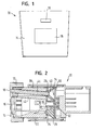
- the switch 10 shown in FIGS. 1 and 2 is an electrical push-button switch which is provided in a motor vehicle for operating a specific functional unit.
- the key switch 10 has a housing 22 and a movable key 12 with a control surface 14.
- the control surface 14 has a transparent symbol 16, which represents the functional unit or a specific function of the functional unit.
- Above the symbol 16 is a light exit surface 18, via which the vehicle occupant is informed about the operating state of the functional unit.
- the housing 22 and / or the button 12, which are each made here in one piece, can also be composed of several parts.
- the structure of the key switch 10 can be seen.
- the button 12 is fixedly connected to a reflector 20 which is guided in a housing 22 and sits on domes 24, 26 of a switching mat 28.
- the switching mat 28 in turn rests on a printed circuit board 30.
- the dome 24, 26 of the switching mat 28 are compressed by the reflector 20 and thus provide a certain feel, which is perceived by the vehicle occupant.
- the switching mat 28 two light sources 32, 34 are arranged in the form of LEDs.
- the first light source 32 which is arranged in a bore 36 of a projecting into the reflector 20 survey 38 of the switching mat 28, is used when needed to illuminate the symbol 16.
- the second light source 34 is disposed in a bore 40 of the mandrel 26 and is dependent the switching state of the key switch 10 is activated.
- the reflector 20 divides an internal space of the key switch 10 in two lighting areas, wherein the subdivision is substantially realized by a partition wall 42.
- the first illumination region is geometrically designed so that the light of the first light source 32 entering the reflector 20 via the bore 36 of the projection 38 uniformly illuminates the transparent symbol 16.
- a light brick 44 is held, which extends from the control surface 14 of the key 12 into the bore 40 of the mandrel 26, in which the second light source 34 is arranged.
- the second light source 34 facing away from the end of the light brick 44 forms the light exit surface 18 in the control surface 14 of the button 12, which indicates the vehicle occupant current switching state of the push-button 10.
- the light brick 44 is fixedly connected to the button 12 or to the reflector 20 and is accordingly moved along with an actuation of the push-button 10 with these.
- the second light source 34 facing the end of the light brick 44 moves in the bore 40, without thereby the flexibility of the switching mat 28 is hindered in the direction of actuation.
- another light guide or a correspondingly formed light shaft can be provided.
Landscapes
- Push-Button Switches (AREA)
- Switch Cases, Indication, And Locking (AREA)
Abstract
Description
- Die Erfindung betrifft einen elektrischen Tastschalter, insbesondere einen elektrischen Tastschalter in einem Kraftfahrzeug zur Bedienung einer Funktionseinheit, mit einem Gehäuse und einer Taste sowie einer Symbolbeleuchtungseinrichtung zur Ausleuchtung eines transparenten Bereichs der Taste, der die mit dem Tastschalter zu bedienende Funktionseinheit oder eine konkrete Funktion der Funktionseinheit symbolisiert, und einer Funktionsbeleuchtungseinrichtung zur Anzeige des Betriebszustands der Funktionseinheit, wobei die Symbolbeleuchtungseinrichtung eine erste Lichtquelle und die Funktionsbeleuchtungseinrichtung eine zweite Lichtquelle und eine abgeschottete Lichtleitstrecke zu einer in die Taste integrierten Lichtaustrittsfläche umfaßt.
- Tastschalter in Kraftfahrzeugen sind im Dunkeln leicht auffindbar, wenn ein Symbol auf der Bedienfläche der Taste mittels einer Symbolbeleuchtungseinrichtung beleuchtet wird. In der Regel wird das Symbol dann beleuchtet, wenn die Scheinwerfer des Fahrzeugs eingeschaltet sind. Bei einigen Tastschaltern ist es sinnvoll, den Fahrzeuginsassen über den aktuellen Schaltzustand des Tastschalters zu informieren, z.B. ob eine Funktionseinheit ein- oder ausgeschaltet ist. Hierfiir kann eine zusätzliche Funktionsbeleuchtungseinrichtung mit einer Lichtaustrittsfläche in der Taste vorgesehen sein, die getrennt von der Symbolbeleuchtung nur in Abhängigkeit vom Betriebszustand der zu bedienenden Funktionseinheit beleuchtet wird.
- In der
EP-A-1 107 268 ist ein Tastschalter der eingangs genannten Art gezeigt, der Teil einer Schaltereinheit mit mehreren Tastschaltern ist. Eine außerhalb des Gehäuses der Schaltereinheit angeordnete Glühbirne dient sowohl zur äußeren "Flutlichtbeleuchtung" der Schaltereinheit als auch zur Beleuchtung der Funktionssymbole der einzelnen Tasten. Hierzu wird das Licht der Glühbirne über Lichtleiter zurück in das Gehäuse und auf die jeweiligen Funktionssymbole geführt. Diese Konstruktion ist jedoch für einzelne Tastschalter ineffizient und benötigt zusätzlichen Bauraum. Außerdem ist diese Lösung nicht für Anwendungen geeignet, bei denen eine äußere Beleuchtung der Tastschalter als störend empfunden werden könnte. - Die Erfindung schafft einen kompakten elektrischen Tastschalter mit einer effizienten Symbol- und Funktionsbeleuchtung.
- Gemäß der Erfindung ist bei einem elektrischen Tastschalter der eingangs genannten Art vorgesehen, daß beide Beleuchtungseinrichtungen in einem durch das Gehäuse definierten Bauraum untergebracht sind. Die Symbolbeleuchtung erfolgt also durch eine innerhalb des Tastschalters angeordnete Lichtquelle, wobei die Lichtleitstrecke der Funktionsbeleuchtung von dieser Lichtquelle und deren Streulicht abgeschottet ist. Damit ist gewährleistet, daß trotz der engen Bauraumverhältnisse weder Streulicht der ersten Lichtquelle zur Lichtaustrittsfläche noch Streulicht der zweiten Lichtquelle zum transparenten Bereich der Taste gelangen kann. Die vollständige Integration der beiden Beleuchtungseinrichtungen in den Tastschalter hat den Vorteil, daß der Tastschalter als eigenständige funktionsfähige Einheit vormontiert und an beliebigen Stellen im Fahrzeug plaziert werden kann.
- Für einen insbesondere in Betätigungsrichtung verkürzten Aufbau können als Lichtquellen platzsparende LEDs verwendet werden, die vorzugsweise unmittelbar auf einer gemeinsamen Leiterplatte angeordnet sind.
- Gemäß der bevorzugten Ausführungsfbrm der Erfindung umfaßt die Lichtleitstrecke einen Lichtleiter, und es ist eine über der zweiten Lichtquelle angeordnete Schaltmatte vorgesehen, wobei zwischen dem Lichtleiter und der Schaltmatte ein Formschluß besteht. Dieser Aufbau ermöglicht ein angenehmes Schaltgefiihl bei der Betätigung des Lichtschalters und einen streulichtfreien Eintritt des Lichts der zweiten Lichtquelle durch die Schaltmatte in den Lichtleiter.
- Besonders vorteilhaft ist dabei eine Ausgestaltung, bei der der Lichtleiter in eine Bohrung der Schaltmatte eintaucht. Dadurch wird die Funktion der Schaltmatte durch eine Bewegung des Lichtleiters in Betätigungsrichtung nicht beeinträchtigt.
- Die Ausbildung des Lichtleiters als Lichtstein, der sich von der Bohrung der Schaltmatte bis zur Taste erstreckt, hat den Vorteil, daß die Abschottung der Lichtleitstrecke von der zweiten Lichtquelle zur Lichtaustrittsfläche auf einfache Weise mit wenigen Bauteilen realisiert werden kann.
- Bei der bevorzugten Ausfizhrungsform der Erfindung ist ferner vorgesehen, daß der Tastschalter einen Reflektor umfaßt, der einen Innenraum des Tastschalters in zwei Beleuchtungsbereiche unterteilt, wobei der erste Beleuchtungsbereich den Austritt des Lichts der ersten Lichtquelle im Wesentlichen auf den transparenten Bereich beschränkt und der Lichtleiter im zweiten Beleuchtungsbereich geführt ist. Der Reflektor übernimmt damit eine Doppelfunktion, die eine Einsparung von Bauteilen und Bauraum ermöglicht.
- Die Erfindung wird nachfolgend anhand eines Ausführungsbeispiels unter Bezugnahme auf die beigefügten Zeichnungen beschrieben. In den Zeichnungen zeigen:
- Fig. 1 eine Vorderansicht eines erfindungsgemäßen elektrischen Tastschalters; und
- Fig. 2 eine seitliche Schnittansicht des Tastschalters aus Fig. 1.
- Der in den Figuren 1 und 2 dargestellte Schalter 10 ist ein elektrischer Tastschalter, der in einem Kraftfahrzeug zur Bedienung einer bestimmten Funktionseinheit vorgesehen ist. Der Tastschalter 10 hat ein Gehäuse 22 und eine bewegbare Taste 12 mit einer Bedienfläche 14. Die Bedienfläche 14 weist ein transparentes Symbol 16 auf, das die Funktionseinheit oder eine konkrete Funktion der Funktionseinheit repräsentiert. Über dem Symbol 16 befindet sich eine Lichtaustrittsfläche 18, über die der Fahrzeuginsasse über den Betriebszustand der Funktionseinheit informiert wird. Das Gehäuse 22 und/oder die Taste 12, die hier jeweils einteilig ausgeführt sind, können auch aus mehreren Teilen zusammengesetzt sein.
- In Figur 2 ist der Aufbau des Tastschalters 10 zu erkennen. Die Taste 12 ist fest mit einem Reflektor 20 verbunden, der in einem Gehäuse 22 geführt ist und auf Domen 24, 26 einer Schaltmatte 28 sitzt. Die Schaltmatte 28 wiederum liegt auf einer Leiterplatte 30 auf. Bei einer Betätigung des Tastschalters 10 durch Drücken der Taste 12 werden die Dome 24, 26 der Schaltmatte 28 durch den Reflektor 20 zusammengedrückt und sorgen so für eine bestimmte Haptik, die vom Fahrzeuginsassen wahrgenommen wird.
- Auf der Schaltmatte 28 sind zwei Lichtquellen 32, 34 in Form von LEDs angeordnet. Die erste Lichtquelle 32, die in einer Bohrung 36 einer in den Reflektor 20 hineinragenden Erhebung 38 der Schaltmatte 28 angeordnet ist, dient bei Bedarf zur Beleuchtung des Symbols 16. Die zweite Lichtquelle 34 ist in einer Bohrung 40 des Doms 26 angeordnet und wird in Abhängigkeit des Schaltzustands des Tastschalters 10 aktiviert.
- Der Reflektor 20 unterteilt einen inneren Bauraum des Tastschalters 10 in zwei Beleuchtungsbereiche, wobei die Unterteilung im wesentlichen durch eine Trennwand 42 realisiert ist. Der erste Beleuchtungsbereich ist geometrisch so gestaltet, daß das über die Bohrung 36 der Erhebung 38 in den Reflektor 20 eintretende Licht der ersten Lichtquelle 32 das transparente Symbol 16 gleichmäßig ausleuchtet.
- Im zweiten Beleuchtungsbereich des Reflektors 20 ist ein Lichtstein 44 gehalten, der sich von der Bedienfläche 14 der Taste 12 bis in die Bohrung 40 des Doms 26 hineinerstreckt, in der die zweite Lichtquelle 34 angeordnet ist. Das der zweiten Lichtquelle 34 abgewandte Ende des Lichtsteins 44 bildet die Lichtaustrittsfläche 18 in der Bedienfläche 14 der Taste 12, die den Fahrzeuginsassen den aktuellen Schaltzustand des Tastschalters 10 anzeigt. Der Lichtstein 44 ist fest mit der Taste 12 bzw. mit dem Reflektor 20 verbunden und wird dementsprechend bei einer Betätigung des Tastschalters 10 mit diesen mitverschoben. Das der zweiten Lichtquelle 34 zugewandte Ende des Lichtsteins 44 bewegt sich dabei in der Bohrung 40, ohne daß dadurch die Flexibilität der Schaltmatte 28 in Betätigungsrichtung behindert wird. Die Funktion der Schaltmatte 28, nämlich die Erzeugung einer vom Fahrzeuginsassen wahrnehmbaren Haptik, wird also nicht beeinträchtigt. Die Bohrung 40 des Doms 26 und das der zweiten Lichtquelle 34 zugewandte Ende des Lichtsteins 44 gehen aber sinngemäß einen Formschluß ein, der für eine vollständig abgeschottete Lichtleitstrecke zwischen der zweiten Lichtquelle 34 und der Lichtaustrittsfläche 18 sorgt.
- Eine gegenseitige Streulichtbeeinflussung der beiden Lichtquellen 32, 34 ist somit trotz der kompakten Bauweise ausgeschlossen, d.h. die Beleuchtung des Symbols 16 wird nicht durch die Beleuchtung des Lichtsteins 44 beeinflußt und umgekehrt.
- Anstelle des Lichtsteins 44 kann auch ein anderer Lichtleiter oder ein entsprechend ausgebildeter Lichtschacht vorgesehen sein.
Claims (6)
- Elektrischer Tastschalter, mit einem Gehäuse (22) und einer Taste (12) sowie einer Symbolbeleuchtungseinrichtung zur Ausleuchtung eines transparenten Bereichs (16) der Taste (12), der die mit dem Tastschalter (10) zu bedienende Funktionseinheit oder eine konkrete Funktion der Funktionseinheit symbolisiert, und einer Funktionsbeleuchtungseinrichtung zur Anzeige des Betriebszustands der Funktionseinheit, wobei die Symbolbeleuchtungseinrichtung eine erste Lichtquelle (32) und die Funktionsbeleuchtungseinrichtung eine zweite Lichtquelle (34) und eine abgeschottete Lichtleitstrecke zu einer in die Taste (12) integrierten Lichtaustrittsfläche (18) umfaßt, dadurch gekennzeichnet, daß beide Beleuchtungseinrichtungen in einem durch das Gehäuse (22) definierten Bauraum untergebracht sind.
- Elektrischer Tastschalter nach Anspruch 1, dadurch gekennzeichnet, daß die beiden Lichtquellen (32, 34) LEDs sind, die unmittelbar auf einer gemeinsamen Leiterplatte (30) angeordnet sind.
- Elektrischer Tastschalter nach Anspruch 1 oder 2, dadurch gekennzeichnet, daß die Lichtleitstrecke einen Lichtleiter umfaßt und eine über der zweiten Lichtquelle (34) angeordnete Schaltmatte (28) vorgesehen ist, wobei zwischen dem Lichtleiter und der Schaltmatte (28) ein Formschluß besteht.
- Elektrischer Tastschalter nach Anspruch 3, dadurch gekennzeichnet, daß der Lichtleiter in eine in eine Bohrung (40) der Schaltmatte (28) eintaucht.
- Elektrischer Tastschalter nach Anspruch 4, dadurch gekennzeichnet, daß der Lichtleiter ein Lichtstein (44) ist, der sich von der Bohrung (40) der Schaltmatte (28) bis zur Taste (12) erstreckt.
- Elektrischer Tastschalter nach einem der Ansprüche 3 bis 5 Ansprüche, dadurch gekennzeichnet, daß der Tastschalter (10) ferner einen Reflektor (20) umfaßt, der einen Innenraum des Tastschalters (10) in zwei Beleuchtungsbereiche unterteilt, wobei der erste Beleuchtungsbereich den Austritt des Lichts der ersten Lichtquelle (32) im Wesentlichen auf den transparenten Bereich (16) beschränkt, und der Lichtleiter im zweiten Beleuchtungsbereich geführt ist.
Applications Claiming Priority (1)
| Application Number | Priority Date | Filing Date | Title |
|---|---|---|---|
| DE200520003663 DE202005003663U1 (de) | 2005-03-08 | 2005-03-08 | Elektrischer Tastschalter |
Publications (4)
| Publication Number | Publication Date |
|---|---|
| EP1701367A2 true EP1701367A2 (de) | 2006-09-13 |
| EP1701367A9 EP1701367A9 (de) | 2006-11-08 |
| EP1701367A3 EP1701367A3 (de) | 2007-08-01 |
| EP1701367B1 EP1701367B1 (de) | 2010-12-15 |
Family
ID=34802190
Family Applications (1)
| Application Number | Title | Priority Date | Filing Date |
|---|---|---|---|
| EP06003487A Expired - Lifetime EP1701367B1 (de) | 2005-03-08 | 2006-02-21 | Elektrischer Tastschalter |
Country Status (6)
| Country | Link |
|---|---|
| US (1) | US7394034B2 (de) |
| EP (1) | EP1701367B1 (de) |
| JP (1) | JP4394651B2 (de) |
| CN (1) | CN100452262C (de) |
| BR (1) | BRPI0600775A (de) |
| DE (2) | DE202005003663U1 (de) |
Cited By (1)
| Publication number | Priority date | Publication date | Assignee | Title |
|---|---|---|---|---|
| WO2009013176A1 (de) * | 2007-07-25 | 2009-01-29 | Huf Hülsbeck & Fürst Gmbh & Co. Kg | Schaltvorrichtung |
Families Citing this family (20)
| Publication number | Priority date | Publication date | Assignee | Title |
|---|---|---|---|---|
| DE202006004575U1 (de) * | 2006-03-22 | 2006-05-18 | Trw Automotive Electronics & Components Gmbh & Co. Kg | Schaltermodul |
| JP2007280780A (ja) * | 2006-04-07 | 2007-10-25 | Calsonic Kansei Corp | プッシュ式スイッチ |
| JP2009009790A (ja) * | 2007-06-27 | 2009-01-15 | Alps Electric Co Ltd | 照光スイッチ |
| JP5271144B2 (ja) * | 2009-04-22 | 2013-08-21 | ナイルス株式会社 | スイッチ |
| CN101882516A (zh) * | 2009-05-08 | 2010-11-10 | 鸿富锦精密工业(深圳)有限公司 | 发光二极管开关 |
| TWM370169U (en) * | 2009-06-10 | 2009-12-01 | Wistron Corp | Push button component with illumination structure and electronic device |
| DE102009041542A1 (de) * | 2009-09-15 | 2011-03-24 | Siemens Aktiengesellschaft | Betätiger mit Signalanzeige |
| TWM381117U (en) * | 2010-01-08 | 2010-05-21 | Darfon Electronics Corp | Key and keyboard with low light dispersion |
| US20120283914A1 (en) * | 2011-05-05 | 2012-11-08 | Karwaczynski Krzysztof W | Vehicle steering wheel control system having integrated electronic control unit |
| KR101704418B1 (ko) | 2012-04-12 | 2017-02-22 | 삼성전자주식회사 | 컨트롤 패널 어셈블리 및 이를 포함하는 세탁기 |
| CN102717713B (zh) * | 2012-06-29 | 2016-06-22 | 惠州市德赛西威汽车电子股份有限公司 | 一种温度旋钮结构 |
| CN104576202A (zh) * | 2013-10-22 | 2015-04-29 | 丹阳市中远车灯有限公司 | 固体继电器信号灯显示结构 |
| DE102014201523B4 (de) * | 2014-01-28 | 2015-11-12 | Behr-Hella Thermocontrol Gmbh | Bedieneinheit insbesondere für eine Fahrzeugkomponente |
| JP6168455B2 (ja) * | 2014-02-13 | 2017-07-26 | パナソニックIpマネジメント株式会社 | スイッチ |
| DE102015200010A1 (de) * | 2015-01-02 | 2016-07-07 | Volkswagen Ag | Fortbewegungsmittel und Anwenderschnittstelle für ein Fortbewegungsmittel |
| EP3697177B1 (de) * | 2019-02-14 | 2021-01-13 | GIRA GIERSIEPEN GmbH & Co. KG | Tastsensor mit integriertem lichtleiter |
| DE102019129120B3 (de) * | 2019-10-29 | 2021-01-21 | Audi Ag | Bedienelement für ein Kraftfahrzeug mit einer Anzeigevorrichtung |
| JP7203785B2 (ja) | 2020-03-31 | 2023-01-13 | 株式会社ソニー・インタラクティブエンタテインメント | 入力デバイス |
| CN115279468B (zh) | 2020-03-31 | 2025-08-15 | 索尼互动娱乐股份有限公司 | 输入设备 |
| CN112109643B (zh) * | 2020-09-14 | 2022-08-30 | 东风汽车有限公司 | 一种车用内饰构件及汽车 |
Citations (1)
| Publication number | Priority date | Publication date | Assignee | Title |
|---|---|---|---|---|
| EP1107268A2 (de) | 1999-12-09 | 2001-06-13 | Valeo Schalter und Sensoren GmbH | Elektrische Schaltereinheit |
Family Cites Families (10)
| Publication number | Priority date | Publication date | Assignee | Title |
|---|---|---|---|---|
| DE3133134A1 (de) | 1981-08-21 | 1983-03-03 | SWF-Spezialfabrik für Autozubehör Gustav Rau GmbH, 7120 Bietigheim-Bissingen | Elektrischer schalter, insbesondere fuer kraftfahrzeuge |
| US4683359A (en) * | 1986-03-13 | 1987-07-28 | Eaton Corporation | Illuminated switch assembly with combined light and light shield |
| DE3817797A1 (de) | 1988-05-26 | 1989-11-30 | Kostal Leopold Gmbh & Co Kg | Elektrischer wippenschalter |
| JPH0476219U (de) * | 1990-11-15 | 1992-07-03 | ||
| JP2553326Y2 (ja) * | 1992-06-23 | 1997-11-05 | 矢崎総業株式会社 | ラバーコンタクトスイッチ |
| DE4414981A1 (de) | 1994-04-29 | 1995-11-02 | Teves Gmbh Alfred | Elektrisches Steuermodul mit Lichtleiter zur Aufnahme mindestens einer Glühlampe |
| DE19840070C2 (de) * | 1998-09-03 | 2003-03-13 | Hella Kg Hueck & Co Patente Ma | Bedienelement für eine Fahrzeugkomponenten-Bedieneinheit |
| FR2812966B1 (fr) * | 2000-08-11 | 2002-12-20 | Telecomm Electronique Aeronaut | Touche lumineuse multi-messages a eclairages independants, notamment pour facade d'equipement aeronautique, et barrette constituee de telles touches |
| EP1376166B1 (de) * | 2002-06-19 | 2011-05-25 | Kabushiki Kaisha Tokai-Rika-Denki-Seisakusho | Folienschaltervorrichtung |
| CN2632830Y (zh) * | 2003-05-23 | 2004-08-11 | 诸爱道 | 开关总成 |
-
2005
- 2005-03-08 DE DE200520003663 patent/DE202005003663U1/de not_active Expired - Lifetime
-
2006
- 2006-02-16 JP JP2006038793A patent/JP4394651B2/ja not_active Expired - Fee Related
- 2006-02-21 DE DE502006008486T patent/DE502006008486D1/de not_active Expired - Lifetime
- 2006-02-21 EP EP06003487A patent/EP1701367B1/de not_active Expired - Lifetime
- 2006-03-06 US US11/368,763 patent/US7394034B2/en not_active Expired - Fee Related
- 2006-03-07 CN CNB2006100597696A patent/CN100452262C/zh not_active Expired - Fee Related
- 2006-03-08 BR BRPI0600775-9A patent/BRPI0600775A/pt not_active IP Right Cessation
Patent Citations (1)
| Publication number | Priority date | Publication date | Assignee | Title |
|---|---|---|---|---|
| EP1107268A2 (de) | 1999-12-09 | 2001-06-13 | Valeo Schalter und Sensoren GmbH | Elektrische Schaltereinheit |
Cited By (2)
| Publication number | Priority date | Publication date | Assignee | Title |
|---|---|---|---|---|
| WO2009013176A1 (de) * | 2007-07-25 | 2009-01-29 | Huf Hülsbeck & Fürst Gmbh & Co. Kg | Schaltvorrichtung |
| US8164016B2 (en) | 2007-07-25 | 2012-04-24 | Huf Hulsbeck & Furst Gmbh & Co. Kg | Switching apparatus |
Also Published As
| Publication number | Publication date |
|---|---|
| DE502006008486D1 (de) | 2011-01-27 |
| BRPI0600775A (pt) | 2006-11-07 |
| DE202005003663U1 (de) | 2005-07-21 |
| EP1701367A3 (de) | 2007-08-01 |
| EP1701367B1 (de) | 2010-12-15 |
| US20060201796A1 (en) | 2006-09-14 |
| CN1832075A (zh) | 2006-09-13 |
| JP4394651B2 (ja) | 2010-01-06 |
| CN100452262C (zh) | 2009-01-14 |
| JP2006253127A (ja) | 2006-09-21 |
| EP1701367A9 (de) | 2006-11-08 |
| US7394034B2 (en) | 2008-07-01 |
Similar Documents
| Publication | Publication Date | Title |
|---|---|---|
| EP1701367B1 (de) | Elektrischer Tastschalter | |
| DE102006041797B4 (de) | Tasten- und Hohllichtleitermechanismus sowie entsprechende Anordnung | |
| EP2951664B1 (de) | Bedieneinrichtung mit optischem fingernavigationsmodul für ein lenkrad | |
| EP1102294A2 (de) | Drehknopf mit Tastfunktion | |
| DE112010004640T5 (de) | Aufbau eines elektrischen Schalters aufweisend einen5-Wege-Toogle-Mechanismus und eine beleuchtete, flexible Schicht | |
| DE102011005051B4 (de) | Lampe mit mindestens einer LED und zwei relativ zueinander bewegbaren Gehäuseteilen | |
| EP1385188B1 (de) | Elektrisches Schaltgerät | |
| DE10225016B4 (de) | Beleuchtbare Betätigungsknopfanordnung | |
| WO2018234362A1 (de) | Kraftfahrzeugbedienvorrichtung | |
| DE102013215719B3 (de) | Tastermodul | |
| DE19738666C1 (de) | Bedieneinheit für insbesondere eine Fahrzeug-Komponente | |
| DE19627212C2 (de) | Betätigungseinheit für eine Fahrzeugkomponente, insbesondere eine Fahrzeug-Klimaanlage | |
| DE69308401T2 (de) | Bedienungstafel mit Berührungstasten für die Regelung einer Klimatisiereinrichtung eines Fahrzeuginnenraums | |
| EP2073232A2 (de) | Elektrischer Schalter | |
| EP0801799B1 (de) | Elektrisches steuermodul mit lichtleiter zur aufnahme mindestens einer glühlampe | |
| DE102006055142B4 (de) | Fahrzeuginnenraumleuchte | |
| EP1873596B1 (de) | Tragbarer Funkfernsteuerungssender mit beleuchteten Tasten | |
| EP1443533B1 (de) | Elektrische Schalter | |
| DE102014201523B4 (de) | Bedieneinheit insbesondere für eine Fahrzeugkomponente | |
| EP0872818B1 (de) | Bedieneinrichtung mit beleuchtetem Tastenfeld | |
| DE2142884A1 (de) | Schalter mit beleuchtungsvorrichtung, insbesondere fuer kraftfahrzeuge | |
| DE3109868A1 (de) | Drucktastenaggregat | |
| DE69229996T2 (de) | Indikator | |
| DE3502259A1 (de) | Flutlichtplatte mit integrierten tasten und vollflaechenausleuchtung | |
| DE102021112451B3 (de) | Steckdose mit elektrischem Schalter |
Legal Events
| Date | Code | Title | Description |
|---|---|---|---|
| PUAI | Public reference made under article 153(3) epc to a published international application that has entered the european phase |
Free format text: ORIGINAL CODE: 0009012 |
|
| AK | Designated contracting states |
Kind code of ref document: A2 Designated state(s): AT BE BG CH CY CZ DE DK EE ES FI FR GB GR HU IE IS IT LI LT LU LV MC NL PL PT RO SE SI SK TR |
|
| AX | Request for extension of the european patent |
Extension state: AL BA HR MK YU |
|
| PUAL | Search report despatched |
Free format text: ORIGINAL CODE: 0009013 |
|
| AK | Designated contracting states |
Kind code of ref document: A3 Designated state(s): AT BE BG CH CY CZ DE DK EE ES FI FR GB GR HU IE IS IT LI LT LU LV MC NL PL PT RO SE SI SK TR |
|
| AX | Request for extension of the european patent |
Extension state: AL BA HR MK YU |
|
| 17P | Request for examination filed |
Effective date: 20071220 |
|
| 17Q | First examination report despatched |
Effective date: 20080124 |
|
| AKX | Designation fees paid |
Designated state(s): CZ DE ES FR GB IT |
|
| GRAP | Despatch of communication of intention to grant a patent |
Free format text: ORIGINAL CODE: EPIDOSNIGR1 |
|
| GRAS | Grant fee paid |
Free format text: ORIGINAL CODE: EPIDOSNIGR3 |
|
| GRAA | (expected) grant |
Free format text: ORIGINAL CODE: 0009210 |
|
| RAP1 | Party data changed (applicant data changed or rights of an application transferred) |
Owner name: VOLKSWAGEN AG Owner name: TRW AUTOMOTIVE ELECTRONICS & COMPONENTS GMBH |
|
| AK | Designated contracting states |
Kind code of ref document: B1 Designated state(s): CZ DE ES FR GB IT |
|
| REG | Reference to a national code |
Ref country code: GB Ref legal event code: FG4D Free format text: NOT ENGLISH |
|
| REF | Corresponds to: |
Ref document number: 502006008486 Country of ref document: DE Date of ref document: 20110127 Kind code of ref document: P |
|
| PG25 | Lapsed in a contracting state [announced via postgrant information from national office to epo] |
Ref country code: CZ Free format text: LAPSE BECAUSE OF FAILURE TO SUBMIT A TRANSLATION OF THE DESCRIPTION OR TO PAY THE FEE WITHIN THE PRESCRIBED TIME-LIMIT Effective date: 20101215 Ref country code: ES Free format text: LAPSE BECAUSE OF FAILURE TO SUBMIT A TRANSLATION OF THE DESCRIPTION OR TO PAY THE FEE WITHIN THE PRESCRIBED TIME-LIMIT Effective date: 20110326 |
|
| PGFP | Annual fee paid to national office [announced via postgrant information from national office to epo] |
Ref country code: ES Payment date: 20110224 Year of fee payment: 6 |
|
| PLBE | No opposition filed within time limit |
Free format text: ORIGINAL CODE: 0009261 |
|
| STAA | Information on the status of an ep patent application or granted ep patent |
Free format text: STATUS: NO OPPOSITION FILED WITHIN TIME LIMIT |
|
| 26N | No opposition filed |
Effective date: 20110916 |
|
| PG25 | Lapsed in a contracting state [announced via postgrant information from national office to epo] |
Ref country code: IT Free format text: LAPSE BECAUSE OF FAILURE TO SUBMIT A TRANSLATION OF THE DESCRIPTION OR TO PAY THE FEE WITHIN THE PRESCRIBED TIME-LIMIT Effective date: 20101215 |
|
| REG | Reference to a national code |
Ref country code: DE Ref legal event code: R097 Ref document number: 502006008486 Country of ref document: DE Effective date: 20110916 |
|
| PGFP | Annual fee paid to national office [announced via postgrant information from national office to epo] |
Ref country code: GB Payment date: 20130227 Year of fee payment: 8 Ref country code: FR Payment date: 20130311 Year of fee payment: 8 |
|
| GBPC | Gb: european patent ceased through non-payment of renewal fee |
Effective date: 20140221 |
|
| REG | Reference to a national code |
Ref country code: FR Ref legal event code: ST Effective date: 20141031 |
|
| PG25 | Lapsed in a contracting state [announced via postgrant information from national office to epo] |
Ref country code: FR Free format text: LAPSE BECAUSE OF NON-PAYMENT OF DUE FEES Effective date: 20140228 Ref country code: GB Free format text: LAPSE BECAUSE OF NON-PAYMENT OF DUE FEES Effective date: 20140221 |
|
| REG | Reference to a national code |
Ref country code: DE Ref legal event code: R082 Ref document number: 502006008486 Country of ref document: DE Representative=s name: PRINZ & PARTNER MBB PATENTANWAELTE RECHTSANWAE, DE Ref country code: DE Ref legal event code: R081 Ref document number: 502006008486 Country of ref document: DE Owner name: VOLKSWAGEN AG, DE Free format text: FORMER OWNERS: TRW AUTOMOTIVE ELECTRONICS & COMPONENTS GMBH, 78315 RADOLFZELL, DE; VOLKSWAGEN AG, 38440 WOLFSBURG, DE Ref country code: DE Ref legal event code: R081 Ref document number: 502006008486 Country of ref document: DE Owner name: BCS AUTOMOTIVE INTERFACE SOLUTIONS GMBH, DE Free format text: FORMER OWNERS: TRW AUTOMOTIVE ELECTRONICS & COMPONENTS GMBH, 78315 RADOLFZELL, DE; VOLKSWAGEN AG, 38440 WOLFSBURG, DE |
|
| REG | Reference to a national code |
Ref country code: DE Ref legal event code: R082 Ref document number: 502006008486 Country of ref document: DE Representative=s name: PRINZ & PARTNER MBB PATENTANWAELTE RECHTSANWAE, DE Ref country code: DE Ref legal event code: R081 Ref document number: 502006008486 Country of ref document: DE Owner name: VOLKSWAGEN AG, DE Free format text: FORMER OWNERS: BCS AUTOMOTIVE INTERFACE SOLUTIONS GMBH, 78315 RADOLFZELL, DE; VOLKSWAGEN AG, 38440 WOLFSBURG, DE |
|
| PGFP | Annual fee paid to national office [announced via postgrant information from national office to epo] |
Ref country code: DE Payment date: 20240209 Year of fee payment: 19 |
|
| REG | Reference to a national code |
Ref country code: DE Ref legal event code: R119 Ref document number: 502006008486 Country of ref document: DE |
|
| PG25 | Lapsed in a contracting state [announced via postgrant information from national office to epo] |
Ref country code: DE Free format text: LAPSE BECAUSE OF NON-PAYMENT OF DUE FEES Effective date: 20250902 |