EP1698002B1 - Anodengetragene festoxid-brennstoffzellen mit einem cermet-elektrolyt - Google Patents
Anodengetragene festoxid-brennstoffzellen mit einem cermet-elektrolyt Download PDFInfo
- Publication number
- EP1698002B1 EP1698002B1 EP04812652.8A EP04812652A EP1698002B1 EP 1698002 B1 EP1698002 B1 EP 1698002B1 EP 04812652 A EP04812652 A EP 04812652A EP 1698002 B1 EP1698002 B1 EP 1698002B1
- Authority
- EP
- European Patent Office
- Prior art keywords
- cermet
- layer
- anodic
- cathodic
- electrolyte
- Prior art date
- Legal status (The legal status is an assumption and is not a legal conclusion. Google has not performed a legal analysis and makes no representation as to the accuracy of the status listed.)
- Active
Links
- 239000011195 cermet Substances 0.000 title claims description 126
- 239000003792 electrolyte Substances 0.000 title claims description 118
- 239000000446 fuel Substances 0.000 title claims description 78
- 239000007787 solid Substances 0.000 title claims description 33
- 239000010410 layer Substances 0.000 claims description 82
- 229910052751 metal Inorganic materials 0.000 claims description 60
- 239000002184 metal Substances 0.000 claims description 60
- 238000000034 method Methods 0.000 claims description 51
- 239000000843 powder Substances 0.000 claims description 43
- 239000000919 ceramic Substances 0.000 claims description 35
- 239000002002 slurry Substances 0.000 claims description 33
- 238000004519 manufacturing process Methods 0.000 claims description 29
- 239000000203 mixture Substances 0.000 claims description 27
- 150000004706 metal oxides Chemical class 0.000 claims description 23
- 229910044991 metal oxide Inorganic materials 0.000 claims description 22
- 239000002105 nanoparticle Substances 0.000 claims description 20
- 238000005245 sintering Methods 0.000 claims description 19
- 238000000576 coating method Methods 0.000 claims description 18
- 239000000463 material Substances 0.000 claims description 18
- 239000011248 coating agent Substances 0.000 claims description 15
- 229910002076 stabilized zirconia Inorganic materials 0.000 claims description 15
- 229910010293 ceramic material Inorganic materials 0.000 claims description 14
- 229910000422 cerium(IV) oxide Inorganic materials 0.000 claims description 14
- 239000010406 cathode material Substances 0.000 claims description 13
- 239000011229 interlayer Substances 0.000 claims description 11
- 239000002245 particle Substances 0.000 claims description 10
- CETPSERCERDGAM-UHFFFAOYSA-N ceric oxide Chemical compound O=[Ce]=O CETPSERCERDGAM-UHFFFAOYSA-N 0.000 claims description 9
- 238000005266 casting Methods 0.000 claims description 7
- 229910052759 nickel Inorganic materials 0.000 claims description 7
- 238000003825 pressing Methods 0.000 claims description 7
- 229910052723 transition metal Inorganic materials 0.000 claims description 7
- 150000003624 transition metals Chemical class 0.000 claims description 7
- MCMNRKCIXSYSNV-UHFFFAOYSA-N Zirconium dioxide Chemical compound O=[Zr]=O MCMNRKCIXSYSNV-UHFFFAOYSA-N 0.000 claims description 6
- 238000009826 distribution Methods 0.000 claims description 6
- 239000011148 porous material Substances 0.000 claims description 5
- 230000008569 process Effects 0.000 claims description 5
- 150000003839 salts Chemical class 0.000 claims description 5
- 229910003321 CoFe Inorganic materials 0.000 claims description 4
- 230000003197 catalytic effect Effects 0.000 claims description 4
- 238000000151 deposition Methods 0.000 claims description 4
- 229910052707 ruthenium Inorganic materials 0.000 claims description 4
- 238000007581 slurry coating method Methods 0.000 claims description 4
- 239000011343 solid material Substances 0.000 claims description 4
- 229910002075 lanthanum strontium manganite Inorganic materials 0.000 claims description 3
- 229910052697 platinum Inorganic materials 0.000 claims description 3
- 229910052709 silver Inorganic materials 0.000 claims description 3
- 229910018281 LaSrMnO3 Inorganic materials 0.000 claims description 2
- 239000002131 composite material Substances 0.000 claims description 2
- 229910052802 copper Inorganic materials 0.000 claims description 2
- 229910052721 tungsten Inorganic materials 0.000 claims description 2
- 238000013461 design Methods 0.000 description 15
- 238000012545 processing Methods 0.000 description 15
- PXHVJJICTQNCMI-UHFFFAOYSA-N nickel Substances [Ni] PXHVJJICTQNCMI-UHFFFAOYSA-N 0.000 description 14
- 239000003570 air Substances 0.000 description 13
- 239000011230 binding agent Substances 0.000 description 11
- 239000002270 dispersing agent Substances 0.000 description 9
- 239000000758 substrate Substances 0.000 description 9
- 239000004014 plasticizer Substances 0.000 description 7
- 230000002829 reductive effect Effects 0.000 description 7
- 239000002904 solvent Substances 0.000 description 7
- PEDCQBHIVMGVHV-UHFFFAOYSA-N Glycerine Chemical compound OCC(O)CO PEDCQBHIVMGVHV-UHFFFAOYSA-N 0.000 description 6
- 239000012298 atmosphere Substances 0.000 description 6
- 238000001125 extrusion Methods 0.000 description 6
- 230000001590 oxidative effect Effects 0.000 description 6
- 239000000126 substance Substances 0.000 description 6
- XLYOFNOQVPJJNP-UHFFFAOYSA-N water Chemical compound O XLYOFNOQVPJJNP-UHFFFAOYSA-N 0.000 description 6
- 229910021525 ceramic electrolyte Inorganic materials 0.000 description 5
- 238000005516 engineering process Methods 0.000 description 5
- 239000010408 film Substances 0.000 description 5
- 239000000976 ink Substances 0.000 description 5
- 238000003801 milling Methods 0.000 description 5
- 230000009467 reduction Effects 0.000 description 5
- 239000002202 Polyethylene glycol Substances 0.000 description 4
- 239000000654 additive Substances 0.000 description 4
- DOIRQSBPFJWKBE-UHFFFAOYSA-N dibutyl phthalate Chemical compound CCCCOC(=O)C1=CC=CC=C1C(=O)OCCCC DOIRQSBPFJWKBE-UHFFFAOYSA-N 0.000 description 4
- 229920003023 plastic Polymers 0.000 description 4
- 239000004033 plastic Substances 0.000 description 4
- 229920001223 polyethylene glycol Polymers 0.000 description 4
- OKTJSMMVPCPJKN-UHFFFAOYSA-N Carbon Chemical compound [C] OKTJSMMVPCPJKN-UHFFFAOYSA-N 0.000 description 3
- 239000004372 Polyvinyl alcohol Substances 0.000 description 3
- 229920002472 Starch Polymers 0.000 description 3
- 239000013543 active substance Substances 0.000 description 3
- 150000001298 alcohols Chemical class 0.000 description 3
- 230000008901 benefit Effects 0.000 description 3
- 239000003795 chemical substances by application Substances 0.000 description 3
- 238000000280 densification Methods 0.000 description 3
- 230000001419 dependent effect Effects 0.000 description 3
- 230000001627 detrimental effect Effects 0.000 description 3
- 238000010586 diagram Methods 0.000 description 3
- 238000001035 drying Methods 0.000 description 3
- 239000007789 gas Substances 0.000 description 3
- 150000002576 ketones Chemical class 0.000 description 3
- 238000011068 loading method Methods 0.000 description 3
- 150000002736 metal compounds Chemical class 0.000 description 3
- 150000002739 metals Chemical class 0.000 description 3
- 238000002156 mixing Methods 0.000 description 3
- 239000003960 organic solvent Substances 0.000 description 3
- 239000007800 oxidant agent Substances 0.000 description 3
- BASFCYQUMIYNBI-UHFFFAOYSA-N platinum Chemical compound [Pt] BASFCYQUMIYNBI-UHFFFAOYSA-N 0.000 description 3
- 230000010287 polarization Effects 0.000 description 3
- 229920002037 poly(vinyl butyral) polymer Polymers 0.000 description 3
- 229920000642 polymer Polymers 0.000 description 3
- 229920002451 polyvinyl alcohol Polymers 0.000 description 3
- 239000002243 precursor Substances 0.000 description 3
- 238000001179 sorption measurement Methods 0.000 description 3
- 239000008107 starch Substances 0.000 description 3
- 235000019698 starch Nutrition 0.000 description 3
- CSCPPACGZOOCGX-UHFFFAOYSA-N Acetone Chemical compound CC(C)=O CSCPPACGZOOCGX-UHFFFAOYSA-N 0.000 description 2
- 230000004913 activation Effects 0.000 description 2
- 238000005054 agglomeration Methods 0.000 description 2
- 239000000956 alloy Substances 0.000 description 2
- 229910045601 alloy Inorganic materials 0.000 description 2
- 239000012736 aqueous medium Substances 0.000 description 2
- 239000011324 bead Substances 0.000 description 2
- 230000009286 beneficial effect Effects 0.000 description 2
- 230000015572 biosynthetic process Effects 0.000 description 2
- 238000009750 centrifugal casting Methods 0.000 description 2
- 238000004814 ceramic processing Methods 0.000 description 2
- 238000006243 chemical reaction Methods 0.000 description 2
- 150000001875 compounds Chemical class 0.000 description 2
- 230000003247 decreasing effect Effects 0.000 description 2
- 238000011161 development Methods 0.000 description 2
- 230000018109 developmental process Effects 0.000 description 2
- 239000006185 dispersion Substances 0.000 description 2
- 230000000694 effects Effects 0.000 description 2
- 238000000462 isostatic pressing Methods 0.000 description 2
- 230000000670 limiting effect Effects 0.000 description 2
- 239000011159 matrix material Substances 0.000 description 2
- 239000012528 membrane Substances 0.000 description 2
- 239000006259 organic additive Substances 0.000 description 2
- 150000002894 organic compounds Chemical class 0.000 description 2
- 229910052760 oxygen Inorganic materials 0.000 description 2
- 239000001301 oxygen Substances 0.000 description 2
- -1 oxygen ions Chemical class 0.000 description 2
- 230000036961 partial effect Effects 0.000 description 2
- 230000000737 periodic effect Effects 0.000 description 2
- 239000006069 physical mixture Substances 0.000 description 2
- 238000002360 preparation method Methods 0.000 description 2
- 238000007569 slipcasting Methods 0.000 description 2
- 229910052712 strontium Inorganic materials 0.000 description 2
- CIOAGBVUUVVLOB-UHFFFAOYSA-N strontium atom Chemical compound [Sr] CIOAGBVUUVVLOB-UHFFFAOYSA-N 0.000 description 2
- 239000000725 suspension Substances 0.000 description 2
- 238000010345 tape casting Methods 0.000 description 2
- 239000010409 thin film Substances 0.000 description 2
- 230000007704 transition Effects 0.000 description 2
- 229910001233 yttria-stabilized zirconia Inorganic materials 0.000 description 2
- 229910001111 Fine metal Inorganic materials 0.000 description 1
- KJTLSVCANCCWHF-UHFFFAOYSA-N Ruthenium Chemical compound [Ru] KJTLSVCANCCWHF-UHFFFAOYSA-N 0.000 description 1
- BQENXCOZCUHKRE-UHFFFAOYSA-N [La+3].[La+3].[O-][Mn]([O-])=O.[O-][Mn]([O-])=O.[O-][Mn]([O-])=O Chemical compound [La+3].[La+3].[O-][Mn]([O-])=O.[O-][Mn]([O-])=O.[O-][Mn]([O-])=O BQENXCOZCUHKRE-UHFFFAOYSA-N 0.000 description 1
- 230000002411 adverse Effects 0.000 description 1
- 239000012080 ambient air Substances 0.000 description 1
- 239000002518 antifoaming agent Substances 0.000 description 1
- 239000003125 aqueous solvent Substances 0.000 description 1
- QVGXLLKOCUKJST-UHFFFAOYSA-N atomic oxygen Chemical compound [O] QVGXLLKOCUKJST-UHFFFAOYSA-N 0.000 description 1
- 238000000498 ball milling Methods 0.000 description 1
- 229910052799 carbon Inorganic materials 0.000 description 1
- 239000003054 catalyst Substances 0.000 description 1
- 239000006257 cathode slurry Substances 0.000 description 1
- 238000003693 cell processing method Methods 0.000 description 1
- 239000000084 colloidal system Substances 0.000 description 1
- 230000002860 competitive effect Effects 0.000 description 1
- 238000003618 dip coating Methods 0.000 description 1
- 239000012153 distilled water Substances 0.000 description 1
- 230000009977 dual effect Effects 0.000 description 1
- 238000003487 electrochemical reaction Methods 0.000 description 1
- 230000005518 electrochemistry Effects 0.000 description 1
- 239000011267 electrode slurry Substances 0.000 description 1
- 239000002001 electrolyte material Substances 0.000 description 1
- 238000001704 evaporation Methods 0.000 description 1
- 230000008020 evaporation Effects 0.000 description 1
- 230000001747 exhibiting effect Effects 0.000 description 1
- 230000002349 favourable effect Effects 0.000 description 1
- 239000012467 final product Substances 0.000 description 1
- 239000010419 fine particle Substances 0.000 description 1
- 238000010304 firing Methods 0.000 description 1
- 229910001938 gadolinium oxide Inorganic materials 0.000 description 1
- 229940075613 gadolinium oxide Drugs 0.000 description 1
- CMIHHWBVHJVIGI-UHFFFAOYSA-N gadolinium(iii) oxide Chemical compound [O-2].[O-2].[O-2].[Gd+3].[Gd+3] CMIHHWBVHJVIGI-UHFFFAOYSA-N 0.000 description 1
- 229910021526 gadolinium-doped ceria Inorganic materials 0.000 description 1
- 230000014509 gene expression Effects 0.000 description 1
- 230000009477 glass transition Effects 0.000 description 1
- 238000000227 grinding Methods 0.000 description 1
- 238000010438 heat treatment Methods 0.000 description 1
- 239000008240 homogeneous mixture Substances 0.000 description 1
- 239000001866 hydroxypropyl methyl cellulose Substances 0.000 description 1
- 229920003088 hydroxypropyl methyl cellulose Polymers 0.000 description 1
- UFVKGYZPFZQRLF-UHFFFAOYSA-N hydroxypropyl methyl cellulose Chemical compound OC1C(O)C(OC)OC(CO)C1OC1C(O)C(O)C(OC2C(C(O)C(OC3C(C(O)C(O)C(CO)O3)O)C(CO)O2)O)C(CO)O1 UFVKGYZPFZQRLF-UHFFFAOYSA-N 0.000 description 1
- 235000010979 hydroxypropyl methyl cellulose Nutrition 0.000 description 1
- 230000006872 improvement Effects 0.000 description 1
- 238000010348 incorporation Methods 0.000 description 1
- 229910052746 lanthanum Inorganic materials 0.000 description 1
- 239000007788 liquid Substances 0.000 description 1
- 239000002609 medium Substances 0.000 description 1
- 239000002923 metal particle Substances 0.000 description 1
- 229920000609 methyl cellulose Polymers 0.000 description 1
- 239000001923 methylcellulose Substances 0.000 description 1
- 238000012986 modification Methods 0.000 description 1
- 230000004048 modification Effects 0.000 description 1
- 238000000465 moulding Methods 0.000 description 1
- KBJMLQFLOWQJNF-UHFFFAOYSA-N nickel(II) nitrate Inorganic materials [Ni+2].[O-][N+]([O-])=O.[O-][N+]([O-])=O KBJMLQFLOWQJNF-UHFFFAOYSA-N 0.000 description 1
- 239000012457 nonaqueous media Substances 0.000 description 1
- AHKZTVQIVOEVFO-UHFFFAOYSA-N oxide(2-) Chemical compound [O-2] AHKZTVQIVOEVFO-UHFFFAOYSA-N 0.000 description 1
- 238000007649 pad printing Methods 0.000 description 1
- 238000010422 painting Methods 0.000 description 1
- 229910052763 palladium Inorganic materials 0.000 description 1
- 230000000704 physical effect Effects 0.000 description 1
- 239000010970 precious metal Substances 0.000 description 1
- 239000002994 raw material Substances 0.000 description 1
- 230000009257 reactivity Effects 0.000 description 1
- 229910052703 rhodium Inorganic materials 0.000 description 1
- 238000007650 screen-printing Methods 0.000 description 1
- 238000007789 sealing Methods 0.000 description 1
- 230000035939 shock Effects 0.000 description 1
- 239000004332 silver Substances 0.000 description 1
- 239000007784 solid electrolyte Substances 0.000 description 1
- 239000000243 solution Substances 0.000 description 1
- 238000005507 spraying Methods 0.000 description 1
- 239000010935 stainless steel Substances 0.000 description 1
- 229910001220 stainless steel Inorganic materials 0.000 description 1
- 238000003860 storage Methods 0.000 description 1
- 238000012360 testing method Methods 0.000 description 1
- 230000001988 toxicity Effects 0.000 description 1
- 231100000419 toxicity Toxicity 0.000 description 1
- 238000012546 transfer Methods 0.000 description 1
- 238000006276 transfer reaction Methods 0.000 description 1
- 150000003623 transition metal compounds Chemical class 0.000 description 1
- 238000007740 vapor deposition Methods 0.000 description 1
Images


Classifications
-
- H—ELECTRICITY
- H01—ELECTRIC ELEMENTS
- H01M—PROCESSES OR MEANS, e.g. BATTERIES, FOR THE DIRECT CONVERSION OF CHEMICAL ENERGY INTO ELECTRICAL ENERGY
- H01M8/00—Fuel cells; Manufacture thereof
- H01M8/10—Fuel cells with solid electrolytes
- H01M8/12—Fuel cells with solid electrolytes operating at high temperature, e.g. with stabilised ZrO2 electrolyte
- H01M8/1213—Fuel cells with solid electrolytes operating at high temperature, e.g. with stabilised ZrO2 electrolyte characterised by the electrode/electrolyte combination or the supporting material
-
- H—ELECTRICITY
- H01—ELECTRIC ELEMENTS
- H01M—PROCESSES OR MEANS, e.g. BATTERIES, FOR THE DIRECT CONVERSION OF CHEMICAL ENERGY INTO ELECTRICAL ENERGY
- H01M8/00—Fuel cells; Manufacture thereof
- H01M8/10—Fuel cells with solid electrolytes
- H01M8/12—Fuel cells with solid electrolytes operating at high temperature, e.g. with stabilised ZrO2 electrolyte
- H01M8/124—Fuel cells with solid electrolytes operating at high temperature, e.g. with stabilised ZrO2 electrolyte characterised by the process of manufacturing or by the material of the electrolyte
-
- H—ELECTRICITY
- H01—ELECTRIC ELEMENTS
- H01M—PROCESSES OR MEANS, e.g. BATTERIES, FOR THE DIRECT CONVERSION OF CHEMICAL ENERGY INTO ELECTRICAL ENERGY
- H01M4/00—Electrodes
- H01M4/86—Inert electrodes with catalytic activity, e.g. for fuel cells
- H01M4/8605—Porous electrodes
- H01M4/8621—Porous electrodes containing only metallic or ceramic material, e.g. made by sintering or sputtering
-
- H—ELECTRICITY
- H01—ELECTRIC ELEMENTS
- H01M—PROCESSES OR MEANS, e.g. BATTERIES, FOR THE DIRECT CONVERSION OF CHEMICAL ENERGY INTO ELECTRICAL ENERGY
- H01M4/00—Electrodes
- H01M4/86—Inert electrodes with catalytic activity, e.g. for fuel cells
- H01M4/8605—Porous electrodes
- H01M4/8626—Porous electrodes characterised by the form
-
- H—ELECTRICITY
- H01—ELECTRIC ELEMENTS
- H01M—PROCESSES OR MEANS, e.g. BATTERIES, FOR THE DIRECT CONVERSION OF CHEMICAL ENERGY INTO ELECTRICAL ENERGY
- H01M4/00—Electrodes
- H01M4/86—Inert electrodes with catalytic activity, e.g. for fuel cells
- H01M4/8647—Inert electrodes with catalytic activity, e.g. for fuel cells consisting of more than one material, e.g. consisting of composites
- H01M4/8652—Inert electrodes with catalytic activity, e.g. for fuel cells consisting of more than one material, e.g. consisting of composites as mixture
-
- H—ELECTRICITY
- H01—ELECTRIC ELEMENTS
- H01M—PROCESSES OR MEANS, e.g. BATTERIES, FOR THE DIRECT CONVERSION OF CHEMICAL ENERGY INTO ELECTRICAL ENERGY
- H01M4/00—Electrodes
- H01M4/86—Inert electrodes with catalytic activity, e.g. for fuel cells
- H01M4/88—Processes of manufacture
- H01M4/8825—Methods for deposition of the catalytic active composition
- H01M4/8828—Coating with slurry or ink
-
- H—ELECTRICITY
- H01—ELECTRIC ELEMENTS
- H01M—PROCESSES OR MEANS, e.g. BATTERIES, FOR THE DIRECT CONVERSION OF CHEMICAL ENERGY INTO ELECTRICAL ENERGY
- H01M4/00—Electrodes
- H01M4/86—Inert electrodes with catalytic activity, e.g. for fuel cells
- H01M4/88—Processes of manufacture
- H01M4/8878—Treatment steps after deposition of the catalytic active composition or after shaping of the electrode being free-standing body
- H01M4/8882—Heat treatment, e.g. drying, baking
- H01M4/8885—Sintering or firing
-
- H—ELECTRICITY
- H01—ELECTRIC ELEMENTS
- H01M—PROCESSES OR MEANS, e.g. BATTERIES, FOR THE DIRECT CONVERSION OF CHEMICAL ENERGY INTO ELECTRICAL ENERGY
- H01M4/00—Electrodes
- H01M4/86—Inert electrodes with catalytic activity, e.g. for fuel cells
- H01M4/90—Selection of catalytic material
- H01M4/9041—Metals or alloys
- H01M4/905—Metals or alloys specially used in fuel cell operating at high temperature, e.g. SOFC
- H01M4/9066—Metals or alloys specially used in fuel cell operating at high temperature, e.g. SOFC of metal-ceramic composites or mixtures, e.g. cermets
-
- H—ELECTRICITY
- H01—ELECTRIC ELEMENTS
- H01M—PROCESSES OR MEANS, e.g. BATTERIES, FOR THE DIRECT CONVERSION OF CHEMICAL ENERGY INTO ELECTRICAL ENERGY
- H01M4/00—Electrodes
- H01M4/86—Inert electrodes with catalytic activity, e.g. for fuel cells
- H01M4/90—Selection of catalytic material
- H01M4/92—Metals of platinum group
-
- H—ELECTRICITY
- H01—ELECTRIC ELEMENTS
- H01M—PROCESSES OR MEANS, e.g. BATTERIES, FOR THE DIRECT CONVERSION OF CHEMICAL ENERGY INTO ELECTRICAL ENERGY
- H01M8/00—Fuel cells; Manufacture thereof
- H01M8/10—Fuel cells with solid electrolytes
- H01M8/12—Fuel cells with solid electrolytes operating at high temperature, e.g. with stabilised ZrO2 electrolyte
- H01M8/124—Fuel cells with solid electrolytes operating at high temperature, e.g. with stabilised ZrO2 electrolyte characterised by the process of manufacturing or by the material of the electrolyte
- H01M8/1246—Fuel cells with solid electrolytes operating at high temperature, e.g. with stabilised ZrO2 electrolyte characterised by the process of manufacturing or by the material of the electrolyte the electrolyte consisting of oxides
- H01M8/1253—Fuel cells with solid electrolytes operating at high temperature, e.g. with stabilised ZrO2 electrolyte characterised by the process of manufacturing or by the material of the electrolyte the electrolyte consisting of oxides the electrolyte containing zirconium oxide
-
- H—ELECTRICITY
- H01—ELECTRIC ELEMENTS
- H01M—PROCESSES OR MEANS, e.g. BATTERIES, FOR THE DIRECT CONVERSION OF CHEMICAL ENERGY INTO ELECTRICAL ENERGY
- H01M8/00—Fuel cells; Manufacture thereof
- H01M8/10—Fuel cells with solid electrolytes
- H01M8/12—Fuel cells with solid electrolytes operating at high temperature, e.g. with stabilised ZrO2 electrolyte
- H01M8/124—Fuel cells with solid electrolytes operating at high temperature, e.g. with stabilised ZrO2 electrolyte characterised by the process of manufacturing or by the material of the electrolyte
- H01M8/1246—Fuel cells with solid electrolytes operating at high temperature, e.g. with stabilised ZrO2 electrolyte characterised by the process of manufacturing or by the material of the electrolyte the electrolyte consisting of oxides
- H01M8/126—Fuel cells with solid electrolytes operating at high temperature, e.g. with stabilised ZrO2 electrolyte characterised by the process of manufacturing or by the material of the electrolyte the electrolyte consisting of oxides the electrolyte containing cerium oxide
-
- H—ELECTRICITY
- H01—ELECTRIC ELEMENTS
- H01M—PROCESSES OR MEANS, e.g. BATTERIES, FOR THE DIRECT CONVERSION OF CHEMICAL ENERGY INTO ELECTRICAL ENERGY
- H01M2300/00—Electrolytes
- H01M2300/0017—Non-aqueous electrolytes
- H01M2300/0065—Solid electrolytes
- H01M2300/0068—Solid electrolytes inorganic
- H01M2300/0071—Oxides
- H01M2300/0074—Ion conductive at high temperature
- H01M2300/0077—Ion conductive at high temperature based on zirconium oxide
-
- Y—GENERAL TAGGING OF NEW TECHNOLOGICAL DEVELOPMENTS; GENERAL TAGGING OF CROSS-SECTIONAL TECHNOLOGIES SPANNING OVER SEVERAL SECTIONS OF THE IPC; TECHNICAL SUBJECTS COVERED BY FORMER USPC CROSS-REFERENCE ART COLLECTIONS [XRACs] AND DIGESTS
- Y02—TECHNOLOGIES OR APPLICATIONS FOR MITIGATION OR ADAPTATION AGAINST CLIMATE CHANGE
- Y02E—REDUCTION OF GREENHOUSE GAS [GHG] EMISSIONS, RELATED TO ENERGY GENERATION, TRANSMISSION OR DISTRIBUTION
- Y02E60/00—Enabling technologies; Technologies with a potential or indirect contribution to GHG emissions mitigation
- Y02E60/30—Hydrogen technology
- Y02E60/50—Fuel cells
-
- Y—GENERAL TAGGING OF NEW TECHNOLOGICAL DEVELOPMENTS; GENERAL TAGGING OF CROSS-SECTIONAL TECHNOLOGIES SPANNING OVER SEVERAL SECTIONS OF THE IPC; TECHNICAL SUBJECTS COVERED BY FORMER USPC CROSS-REFERENCE ART COLLECTIONS [XRACs] AND DIGESTS
- Y02—TECHNOLOGIES OR APPLICATIONS FOR MITIGATION OR ADAPTATION AGAINST CLIMATE CHANGE
- Y02P—CLIMATE CHANGE MITIGATION TECHNOLOGIES IN THE PRODUCTION OR PROCESSING OF GOODS
- Y02P70/00—Climate change mitigation technologies in the production process for final industrial or consumer products
- Y02P70/50—Manufacturing or production processes characterised by the final manufactured product
Definitions
- This invention relates generally to fuel cells, and more specifically, to an anode-supported solid oxide fuel cells or SOFCs, and methods of manufacture, wherein the fuel cells possess enhanced physical properties, including electrochemical properties through application of a novel cermet electrolyte .
- a typical tubular SOFC includes a ceramic membrane for conducting oxygen-ions onto which an air electrode (i.e., cathode) and the fuel electrode (i.e., anode) are deposited. Oxygen is converted at the cathode to oxygen ions, which diffuse through the membrane and react with the fuel at the anode. The electrons generated at the anode then migrate through the external load to complete the circuit.
- an air electrode i.e., cathode
- the fuel electrode i.e., anode
- the electrolyte layer in an electrolyte-supported SOFC must be dense, gas tight and very thin (preferably a few microns).
- Technology for depositing thin electrolyte films onto porous electrode substrates is currently under development (see H. P. Buchkremer et al., "Advances in Manufacturing and Operation of Anode, Supported SOFC Cells and Stacks", Proceedings of the Third European Solid Oxide Fuel Cell Forum, June 1998, p. 143-149 ).
- Cathodes are made of ceramic materials and their strength is lower than anodes made of cermets, i.e., composites of ceramic and metal.
- Typical cathode-supported SOFCs are economically unattractive because they require capital-intensive depositing techniques, such as electrochemical vapor deposition (see U.S. Patent No. 5,989,634 to Isenberg ).
- anode-supported SOFCs are attracting increased attention since they can be fabricated at lower cost while maintaining high mechanical structural strength and providing high power density (see U.S. Patent No. 6,436,565 to Song et al. ).
- existing anode-supported SOFCs still lack superior electrochemical performance and structural reliability. This is mainly due to thermal expansion coefficient mismatch between the anode cermet and the conventional ceramic electrolyte, which can result in cell failure during fabrication, or when under operating conditions.
- EP 1 202 369 A1 relates to a solid oxide fuel cell having a supported electrolyte film, comprising an electrolyte film comprised of a first solid electrolyte exhibiting oxide ion conductivity, a substrate for a fuel electrode which is bonded to a surface of the electrolyte film and an air electrode which is bonded to the other surface of the electrolyte film forming in total an electrolyte-electrode assembly.
- the present invention provides a solid oxide fuel cell according to claim 1, a fuel cell stack according to claim 13 and a method for manufacturing a solid oxide fuel cell according to claim 14. Further developments of the present invention are set out in the dependent claims.
- the present invention broadly relates to solid oxide fuel cells (SOFC), which comprise an internal fuel electrode (anode) serving as a support, an intermediate cermet electrolyte, and an external air electrode (cathode), wherein the cermet electrolyte comprises a minor metal phase dispersed throughout a ceramic material.
- SOFC solid oxide fuel cells
- the SOFC can also include electrode current collectors.
- the anode may be fabricated from a transition metal (e.g., preferably Ni) and a ceramic (e.g., stabilized-zirconia or doped-ceria), a cermet, which may also provide physical support for the entire cell.
- the electrical conductivity of the anode depends on the metal content.
- the electrolyte is made by incorporating a small amount (up to 15 vol%) of the same transition metal as used in the anode with a ceramic (e.g., stabilized-zirconia, doped-ceria) in the electrolyte, thereby greatly reducing the thermal expansion coefficient mismatch between the anode and the cermet electrolyte layer. This allows for increased metal content (up to 80.0 vol%) in the anode, and thus increased electrical conductivity.
- the metal phase dispersed throughout the anode and the cermet electrolyte may be selected from the transition group of metals of the periodic table of elements, their alloys, and their physical mixtures in elemental or in an uncombined state.
- useful transition metals include, but are not limited to: Ni, Co, Cu, Ag and W. While nickel is often preferred, precious metals, such as platinum and ruthenium are catalytically active and may also be employed.
- the ceramic electrolyte substance used in the cermet anode and the cermet electrolyte is preferably stabilized-zirconia, e.g., (ZrO 2 ) 0.92 (Y 2 O 3 ) 0.08 .
- the ceramic electrolyte substance used in the cermet anode and the cermet electrolyte is preferably doped ceria, e.g., (Ce 0.90 Gd 0.10 )O 1.95 .
- each material can be used over a broad range of temperatures and the selection of the material will depend on design constraints.
- the present invention is relevant to typical solid oxide fuel cell structural designs, including tubular, planar and monolith designs.
- a "monolith” may include virtually any structural configuration that is neither tubular nor planar, as for example, an elongated, flattened tubular shape; a dome of spiral shape, or may also refer to a cell constructed on a third party support material.
- the present invention also broadly relates to several structural configurations, including methods of manufacturing anode-supported SOFC using a novel cermet electrolyte.
- Each of these designs encompasses several preferred manufacturing techniques, which applicability is determined by technical and economic factors.
- tubular substrates are preferably manufactured via extrusion techniques
- planar substrates are preferably fabricated via casting or pressing operations.
- nano-sized particles may be used to create an anode-supported SOFC with the cermet electrolyte.
- the metal or the electrolyte substance may be incorporated in the fuel electrode mixture by employing conventional or nano-sized ceramic powders (e.g., stabilized-zirconia, doped-ceria), or both.
- the nano-sized cermet electrolyte slurry may be aqueous or non-aqueous (i.e ., based on organic solvents, preferably alcohols and/or ketones).
- the step of sintering the fuel electrode, nano-sized cermet electrolyte and air electrodes may be carried out at temperatures ranging from about 1050°C to about 1300°C, or until the nanoscale cermet electrolyte is fully densified under oxidizing atmosphere.
- the step of sintering the cermet electrolyte-coated anode, after the application of the cermet electrolyte slurry of step (ii), may be performed.
- the electrolyte substance may also be incorporated in the anode mixture and the cermet electrolyte slurry through use of conventional ceramic powders, stabilized-zirconia, or doped-ceria, for example.
- the electrochemically active substance can be a metal or a metal oxide.
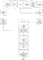
- the metal in the electrochemically active substance is preferably incorporated in the fuel electrode mixture and/or the cermet electrolyte slurry through use of a metal oxide powder (subsequently reduced into elemental metal under SOFC operating conditions) according to the protocols of Figure 3 of the drawings, discussed in further detail below.
- the cermet electrolyte slurry may be aqueous or non-aqueous (i.e., based on organic solvents, preferably alcohols and/or ketones).
- the sintering of the cermet electrolyte-coated fuel electrode may be carried out at temperatures ranging from about 1200°C to about 1600°C, or until the cermet electrolyte is fully dense under oxidizing atmosphere.
- the sintering of the cathodes may be carried out at temperatures in the range of about 1000°C to about 1200°C.
- the metal may be partially incorporated in the fuel electrode mixture and/or the cermet electrolyte slurry by means of metal compounds, preferably metal salts, pre-dissolved in aqueous or non-aqueous solvents.
- metal compounds preferably metal salts
- pore formers e.g., carbon powder, starch, polymer spheres, and so on
- the fuel electrode mixture may be partially incorporated in the fuel electrode mixture and/or the cermet electrolyte slurry by means of metal compounds, preferably metal salts, pre-dissolved in aqueous or non-aqueous solvents.
- pore formers e.g., carbon powder, starch, polymer spheres, and so on
- an anode current collector typically a conductive ink or paste
- the cathode current collector also a conductive ink or paste, for instance, may be coated onto the cathode .
- the anode supported SOFC may further have a deposited interlayer positioned between the fuel electrode support and the cermet electrolyte.
- the invention may further comprise a deposited interlayer between the cermet electrolyte and the cathode.
- FIG. 1A a general view of tubular anode-supported solid oxide fuel cell (SOFC) 10 of the invention is provided as a cylindrical shaped tubular body modified to best illustrate the internal anodic layer 12, intermediate cermet electrolyte 13 and external cathode 14.
- Anode 12 defines an inner tubular bore 15.
- FIG. 1B a general view of planar anode-supported SOFC 16 of the invention is provided as a planar shaped flat body modified to best illustrate the internal anodic layer 17, intermediate cermet electrolyte 18 and external cathode 19.
- a thick cermet fuel electrode i.e., anode
- anode provides mechanical reliability and durability
- a cermet electrolyte allows for better thermal expansion matching and electrochemical performance.
- the use of the anode as the support structure in the fuel cell is most beneficial from the standpoint of performance, as well as for processing.
- anodes of thickness on the order of 0.2 to 1.0 mm, it is possible to achieve high power densities through increased electrical conductivity and reduction of activation overpotential (i.e., voltage losses due to electrochemical charge transfer reactions).
- Thinner substrates would be impractical since the support would be too fragile and electrical conductivity would be insufficient.
- the content of the electrochemically active substance in the cermet is metal.
- the metal content is in the range of 50 vol% through 80 vol %, based on the total solids loading. When the metal content is less than 50 vol %, the cermet anode has poor electrical conductivity. When the metal content of the cermet anode is greater than 50 vol %, a good interfacial bonding is brought about among the metal particles, resulting in an increase in electrical conductivity.
- the porosity of the anode may be increased, so that concentration polarization (i.e ., voltage losses associated with resistance to gas flow through porous electrodes) is kept at a minimum level.
- concentration polarization i.e ., voltage losses associated with resistance to gas flow through porous electrodes
- the reduction of metal oxide powders into metal under a reducing atmosphere allows for porosity to be created in the anode substrate, thus the need for higher contents of metal oxide in the fuel electrode mixture.
- Additional porosity can be created via the use of artificial pore formers (e.g ., carbon powder, starch, polymer spheres), subsequently burned out during sintering. Maximum amounts of pore-forming agents are fixed at 50 vol %, based on the total solids loading, since higher ratios can lead to poor mechanical strength.
- metal contents of the cermet anode up to 80 vol % were found to be adequate to ensure very high electrical conductivity whilst maintaining sufficient porosity to minimize concentration polarization.
- Higher amounts of metal in the cermet anode can result in a large thermal expansion coefficient mismatch with the coated cermet electrolyte, resulting in cracks developing during processing or cell operation.
- the ceramic material of the cermet anode is discussed in detail below.
- Excessive thermal expansion coefficient mismatch between the anode support and a typical ceramic (i.e., 100% ceramic) electrolyte generally exist when the metal content in the anode is too high. This detrimental effect is usually avoided by limiting the amount of metal present in the anode to, for example, approximately 50 vol % ( see U.S. Patent No. 6,436,565 to Song et al. ), or by using a graded anode structure ( see U.S. Patent No. 6,228,521 to Kim et al. ).
- the present invention allows for large amounts of metal to be included in the anode, specifically, greater than 50 vol %.
- the application of a thin electrolyte layer onto a single-layered anode-supported SOFC is also more viable from a processing standpoint.
- metal contained in the electrolyte exists in its elemental (reduced) form on the fuel side; whilst the presence of air on the cathode side maintains the metal in its metal oxide (oxidized) form ( see Fig. 2 ).
- the thickness of these metal: ceramic and metal oxide: ceramic sub-layers are dependent upon the partial pressures of the fuel and oxidant (air).
- the metal oxide: ceramic electrolyte sub-layer must be dense and gas-tight in order to prevent mixing of the fuel and oxidant gases.
- metal present in the reduced electrolyte sub-layer creates a graded anode structure within the anode, which limits anode/electrolyte interfacial resistance and improves adhesion between these layers. Electrochemical performance is also enhanced through increased three-phase boundary area.
- metal oxide present in the oxidized electrolyte sub-layer creates a very thin and dense electrolyte structure required for high efficiency and lower operating temperatures. The aforementioned behavior is described in greater detail in view of Figure 2 .
- Figure 2 generally shows supporting anode layer 20, "porous" cermet electrolyte layer 22, dense cermet electrolyte layer 24 and cathode layer 26.
- metal is oxidized (e.g ., NiO) in dense cermet electrolyte layer 24, while metal is reduced ( e.g ., Ni) in "porous" cermet electrolyte layer 22.
- Enhanced electrochemical performance results from the existence of electrolyte sub-layers, specifically the metal: ceramic and metal oxide: ceramic layers.
- Electrochemical reactions are also enhanced through increased three-phase boundary domain.
- the metal oxide: ceramic sub-layer, i.e., dense cermet electrolyte layer 24 can become very thin (less than 10 microns).
- the metal oxide phase is sufficiently low ( ⁇ 15 vol%) and well-dispersed in the ceramic matrix, it is possible to achieve a dense, thin, and gas-tight metal oxide: ceramic structure.
- the ionic conductivity of the cermet electrolyte depends directly on the dispersion state and the electrochemical activity of the metal oxide phase. By decreasing the thickness of dense cermet electrolyte layer 24 under operating conditions (through reduction of the metal oxide on the fuel side), the electrolyte electrical resistance is also lowered.
- Figures 3 and 4 disclose processing block diagrams when "conventional-sized” and “nano-sized” powders are used, respectively.
- Nickel-based materials and 8 mol % yttria-stabilized-zirconia are used to illustrate the processing stages, but, as mentioned above, other transition metals and ceramic materials known to those skilled in the art, may be used.
- Aqueous or non-aqueous media may be used to suspend the particulates.
- aqueous media are often preferred because of their cost effectiveness and the enviromnental concerns related to the flammability and toxicity of organic solvents.
- Common processing additives disersants, binders, plasticizers
- dispersants, binders, plasticizers are also used to ensure a well-dispersed, homogeneous and stable mixture (see R. J. Pugh et al., "Surface and Colloid Chemistry in Advanced Ceramics Processing", Marcel Dekker, Oct. 1993 ).
- the characteristics of these mixtures, such as viscosity can be altered by changing the properties or the amounts of the different raw materials. They are then adapted to specific molding procedures.
- the ceramic material used in the fuel electrode support and the electrolyte may be stabilized-zirconia, preferably used for high-temperature SOFC (700°C to 1000°C). This includes preferably 8 mol% yttria-stabilized zirconia ("Y8SZ"), (ZrO 2 ) 0.92 (Y 2 O 3 ) 0.08 .
- Another material of interest is doped-ceria, preferably used for intermediate temperature SOFC (500°C to 700°C). This includes preferably gadolinium-doped ceria ("CGO”), (Ce 0.90 Gd 0.10 )O 1.95 .
- CGO gadolinium-doped ceria
- CGO gadolinium-doped ceria
- each of these materials may be employed over a wide range of temperatures.
- other materials suitable for SOFC electrolyte applications known to those of skill in the art may be used.
- the metal phase used in the cermet fuel electrode (anode) and the cermet electrolyte belongs, preferably, to the transition group of metals of the periodic table of elements, their alloys or physical mixtures.
- Nickel (Ni) is preferred, because of its high electrical conductivity under reducing atmosphere and its cost effectiveness.
- Metal may be introduced in the supported fuel electrode and cermet electrolyte via different precursors, known to those skilled in the art such as metal powders, metal oxide powders, and metal salts (aqueous or non-aqueous).
- Metal oxide powders, such as green NiO, are often preferred because of their cost effectiveness and their adaptability to ceramic processing. The use of fine metal oxide powders is particularly recommended for the cermet electrolyte processing since the metal will remain oxidized under SOFC operating conditions.
- the metal phase range may vary from 50 vol % to 80 vol % in the cermet anode.
- the thickness in the sintered state of the cermet anode will depend on the overall design of the fuel cell. For example, anode thickness in small diameter tubular fuel cells may range from 0.2 mm to 1.0 mm.
- the metal phase range varies from 0.1 vol % to 15 vol % in the cermet electrolyte.
- the thickness of the cermet electrolyte in the sintered state is preferably kept below 500 microns, preferably below 100 microns, more preferably below 50 microns in thickness, and most preferably 5-30 microns in thickness. The actual thickness will depend in part on the size and design of the fuel cell.
- the use of a thick anode support allows for very thin subsequent electrolyte and cathode coatings.
- the reduced thickness of the electrolyte and cathode coatings offers enhanced thermal shock resistance and electrochemical performance.
- the substantial increase in cell performance and stability also enables the cell to operate at lower temperatures. This, in turn, enables cost-effective materials (e.g. , stainless steel) to be used within the stack ( e.g., for cell manifolding).
- the processes described above also allow for depositing thin interlayers between the electrode and the electrolyte structures, without affecting the number of sintering cycles.
- interlayer thin films between the anode and the electrolyte, the electrolyte and the cathode, or both may be to increase cell performance, e.g ., through the use of catalytic materials, or to prevent adverse chemical reactions during sintering.
- These interlayers are optional in the present invention, as shown in both Figures 3 and 4 .
- the interlayer may be comprised of catalysts.
- CGO i.e., ceria gadolinium oxide
- Others may include strontium stabilized zirconia, i.e., SSZ, used with Ni and Ru.
- the interlayers may also contain other catalytically active metals, like Pt, Pd and Rh, to name but a few.
- the geometry of the anode support may be tubular open both ends, tubular closed at one end, planar, or other configurations known in the art.
- extrusion of plastic masses is preferred for manufacturing tubular shapes (open at both ends or closed at one end).
- U.S. Patent No. 6,998,187 entitled “SOLID OXIDE FUEL CELLS WITH NOVEL INTERNAL GEOMETRY", provides examples of variations on manufacturing tubular shapes.
- planar shapes are preferably molded using casting techniques (i.e., liquid processing) or pressing techniques (i.e., dry processing).
- Casting techniques include slip-casting, centrifugal casting, gel-casting, tape casting, and the like.
- Pressing techniques include dry pressing and isostatic pressing. All these processing routes are documented in the literature (see, for example, J. S. Reed, "Principles of Ceramic Processing, 2nd Edition", J. Wiley & Sons, Nov. 1994 ).
- the anode mixture may be a plastic mass molded by extrusion techniques.
- the anode mixture may be an aqueous or non-aqueous slurry molded by casting techniques, preferably slip-casting, centrifugal-casting, gel-casting, and tape-casting.
- the anode mixture may be a dry blend molded by pressing techniques, preferably dry-pressing and isostatic pressing.
- an aqueous or non-aqueous cermet electrolyte slurry containing a small amount of the transition metal compound is applied to the unsintered shaped anode support (tubular or planar).
- the supported anode may be partially sintered prior to electrolyte coating, but this is optional.
- Typical slurry coating techniques known to those skilled in the art may be used. This includes, but is not limited to, spraying, dip-coating, screen printing, pad printing, painting, transferring, and the like. The suitability of the coating technique depends on the shape of the fuel electrode substrate and the thickness of the coated layer. A thin, uniform and well-bonded structure is required to ensure maximum performance and minimum resistance losses.
- a method for manufacturing the anode supported SOFC using the cermet electrode relies on using conventional ceramic powders, conventional metal and/or metal oxide powders, and other metal compounds, including metal salts.
- sintering of these two layers can be achieved without any detrimental damage to the structural integrity of the fuel cell.
- This is in contrast with established fuel cell processing methods whereby the electrode substrate is partially sintered or pre-sintered before the electrolyte coating is applied ( see U.S. Patent No. 6,436,565 to Song et al. ).
- the subsequent firing of the cathode layers ( ⁇ 1200°C) allows for two sintering cycles only.
- the cermet electrolyte-coated anode is sintered at relatively high temperatures, ranging from 1200°C to 1600°C, in order to achieve full densification of the cermet electrolyte coating under an oxidizing atmosphere.
- air electrode slurry i.e., cathode slurry
- cathode slurry containing a mixture of cathode material and ceramic electrolyte material
- a second air electrode containing a single-phase cathode material is then applied onto the dry primary cathode coating.
- Preferred cathode materials belong to the following group of perovskites: LaSrMnO 3 , LaSnFO 3 , (LaSr)(CoFe)O 3 , LaCaMnO 3 and (LaCa)(CoFe)O 3 .
- Air electrode coatings are then generally sintered at relatively low temperatures, typically less than 1200°C. Lower temperature sintering is used since the chemical reactivity at the cathode/electrolyte interface usually increases at higher temperatures, which in turn results in the potential formation of resistive secondary phases ( see P. J. Gellings et al., "The CRC Handbook of Solid State Electrochemistry", CRC Press, Dec. 1996 ).
- the use of an interlayer between the electrolyte and the first cathode may help to prevent the formation of such resistive compounds at high temperatures, however in this embodiment the interlayer is optional.
- Nano-sized powders have an advantage over conventional ceramic powders in that their high surface area allows them to be densified at relatively low sintering temperatures. Therefore, the use of nano-sized ceramic and metal powders can significantly reduce the complete densification of the cermet electrolyte.
- the cathodes can be applied on the unsintered electrolyte coating, and the entire cell (i.e., anode support, cermet electrolyte and cathodes) can be co-sintered in a single cycle, at temperatures below 1200°C.
- Figure 4 shows nano-sized metal and ceramic powders being used in a manufacturing process of the invention, for anode and cermet electrolyte fabrication (described supra ).
- the incorporation of nano-sized powders in the cermet electrolyte enables significantly lower sintering temperature.
- Very high surface area (e . g ., > 100 m 2 /g) metal oxide (e.g., green NiO) and ceramic (e.g., Y8SZ) powders can reduce the sintering temperature of the cermet electrolyte to below 1200°C.
- the cathode layers (as described supra ) onto the unsintered cermet electrolyte-coated anode, and sinter the multiple layers at temperatures below 1200°C, so that the electrolyte may become fully dense.
- the use of nano-sized powders is optional in the manufacturing of the supported fuel electrode, and can also be partially incorporated along with "conventional" powders.
- the optional nano-sized materials aid in minimizing manufacturing costs, whilst electrical conductivity and mechanical stability are optimized.
- single stage sintering in the fabrication the anode-supported SOFC of this invention provide a significant technological advance compared to the traditional multi or three sintering stages required in most SOFC manufacturing processes.
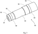
- FIG. 5 a general view of tubular anode-supported solid oxide fuel cell (SOFC) 50 of the invention is provided as a cylindrical shaped tubular body modified to best illustrate the internal anodic layer 52, intermediate cermet electrolyte 54 and external cathode 56.
- Anode 52 defines an inner bore 57.
- screen printed anode and cathode current collectors 58 and 59 are also shown in this embodiment.
- anode current collection generally relies on using metallic inserts (not shown).
- the high electrical conductivity of metallic inserts allows the transfer of electrons from the anode through multiple physical contact points.
- the main disadvantage of this technique is the problem of maintaining good physical contact between the metal inserts and the anode coating, under reducing atmosphere and over extended periods of time. Generally, physical contact is lost over time, due to instability of the metallic inserts under operating conditions.
- the use of a highly conductive metal-rich supported anode allows for conductive ink or paste to be applied directly onto the fuel electrode, without the use of any physical inserts into the tube ( see Fig. 5 ). This in turn is favorable to the electrochemical performance of the cell, since fuel feeding is not hindered by physical obstacles, and fuel is distributed more uniformly to the anode reaction sites.
- the use of a highly conductive cermet anode support is also beneficial for simplifying the anode current collection design.
- physical metallic inserts are used for drawing the electrons from the anode under operating conditions.
- these metallic inserts are prone to dimensional instability at operating temperatures, and the efficiency of the current collector is lowered if good physical contact is not maintained.
- the use of stable conductive inks or pastes applied directly onto the highly conductive fuel electrode is therefore preferred.
- Tubular fuel electrode supports are preferably molded via extrusion of pastes, i.e., plastic masses ( see J. Benbow et al., "Paste Flow and Extrusion", Clarendon Press, Jan. 1993 ).
- a green oxide, NiO powder is mixed with a Y8SZ powder, so that following reduction of NiO, the amount of Ni introduced in the mixture ranges from 30 to 80 vol %.
- the paste composition further includes distilled water (carrier), methylcellulose or hydroxypropyl methylcellulose (binder), and glycerol or polyethylene glycol (plasticizer).
- Appropriate paste compositions can include 70 to 90 wt % solids loading (NiO + Y8SZ), 5 to 25 wt % water, 1 to 15 wt% binder, and 0.1 to 5 wt% plasticizer.
- the composition is then mixed under conditions of high shear, using a high-shear mixer, such as a sigma-blade mixer, so that a homogeneous plastic mass is formed.
- Optional additives include pore formers (e.g ., carbon powder, starch, and polymer beads) and a solution of Ni(NO 3 ) 2 pre-dissolved in water (up to 15 wt%).
- pore formers e.g ., carbon powder, starch, and polymer beads
- Ni(NO 3 ) 2 pre-dissolved in water
- the anode tube may then be extruded by forcing the paste through a die at elevated pressure (e.g ., 1 to 50 kN).
- elevated pressure e.g . 1 to 50 kN
- the shape of the die determines the cross-sectional geometry of the extruded tubes. For example, tubes having an outer diameter of 5 mm and an inner diameter of 4 mm have successfully been extruded and tested for electrochemical performance.
- Extruded tubes may be dried in ambient air over a few hours. Shorter drying times are achieved by using a temperature/humidity chamber where the humidity is controlled. The humidity is gradually decreased from high starting settings, 90 to 100% RH, until the tube is fully dry.
- the cermet electrolyte slurry is a multi-component system, containing in particular a solvent (20 to 60 wt%), an inorganic phase (40 to 80 wt%), a dispersing agent (0.1 to 3 wt%), a binding agent (1 to 15 wt%), and a plasticizing agent (1 to 15 wt%).
- the solvent allows the powders to be dispersed and ensures that the organic components are dissolved.
- Water is the preferred medium, but easier processing is often achieved by using organic media, such as alcohols and ketones.
- the inorganic phase is made of a primary Y8SZ phase and a secondary green NiO phase, so that, following reduction of NiO, the amount of Ni introduced in the mixture ranges from 0.1 - 15.0 vol %.
- the properties required from an ideally sinterable powder to produce a theoretically dense coating are a fine particle size (i.e., 0.1 to 1.0 micron), a narrow particle size distribution, an equiaxed shape, and a non-agglomerated state.
- the dispersing agent (dispersant) is necessary to obtain good, stable de-agglomeration and dispersion of the Y8SZ and NiO particles in the solvent, and to stabilize the suspension with a high solids: organic ratio.
- Commercial dispersants are readily available and should be tested for efficiency in the required solvent. For example, "KD2" (from ICI) was proven to be an effective dispersant for Y8SZ and NiO in acetone.
- the binding agent (binder) is added to the slurry in order to enhance the strength of the unsintered coating.
- the binder forms organic bridges, resulting in strong adhesion after evaporation of solvent.
- Polyvinyl alcohol (PVA) and polyvinyl butyral (PVB) are examples of suitable binders for water-based slurries and organic media-based slurries, respectively. Additional suitable binders known to those skilled in the art may also be used.
- a plasticizing agent is added to the slurry to reduce the glass transition of the binder and for ease of handling and storage.
- the invention contemplates, but is not limited to common plasticizers for PVA, such as polyethylene glycol, glycerol and atmospheric water.
- common plasticizers for PVB include, but are not limited to, dibutyl phthalate (DBP) and polyethylene glycol (PEG).
- a particularly effective method for dispersing the ceramic and metal oxide powder in the solvent is milling and mixing. This breaks down the naturally occurring agglomerates in the starting powder and promotes the adsorption of dispersant.
- the most common milling method is ball-milling, but more aggressive milling techniques, for example vibratory milling, are preferred to ensure more effective de-agglomeration of the powders. This requires the use of grinding media, preferably stabilized-zirconia beads.
- the sequence of addition of organic additives is important because of the competing adsorption of the different organic additives onto the powders.
- slurry processing is performed in two stages. Firstly, the powders are immersed in the solvent, and the dispersant is mixed in, for up to 24 hours. When a homogeneous mixture is obtained and the particles are appropriately dispersed, the binder and plasticizer are added for a second milling/mixing step, again for up to 24 hours. The dispersant is added before the other organic compounds to prevent competitive adsorption onto the particle surface.
- anode support tubes can be dip-coated in the cermet electrolyte slurry.
- the thickness of the coating is directly dependent upon the viscosity of the slurry. Thin layers are obtained when very low viscosity slurries are used, typically ⁇ 50 mPa-s.
- the cermet electrolyte-coated anode support is sintered between 1200°C and 1600°C, or until the cermet electrolyte is fully dense.
- the heating rate from room temperature up to 600°C should be kept relatively low (e.g ., ⁇ 2°C/min) to avoid any failure in the final product due to a non-homogeneous burn out of the organic compounds.
- the dwell time is preferably between 0.5 and 4.0 hours.
- the first cathode layer is a mixture of cathode material (e.g., 50 wt%) and Y8SZ ( e.g., 50 wt%).
- the preferred cathode materials are La 1-x Sr x MnO 3 and La 1-x Sn x FeO 3 , wherein x is between 0.1 and 0.5.
- the second electrode is a single-phase cathode material, used for enhanced electrical conductivity, typically consisting of the aforementioned preferred cathode materials.
- Air electrodes can be painted or sprayed, for example using an airbrush, however, other methods know in the art are equally suitable. After drying, they are sintered at relatively low temperatures, typically below 1200°C, with a dwell time preferably between 0.5 and 4.0 hours.
Landscapes
- Chemical & Material Sciences (AREA)
- Engineering & Computer Science (AREA)
- Electrochemistry (AREA)
- General Chemical & Material Sciences (AREA)
- Chemical Kinetics & Catalysis (AREA)
- Manufacturing & Machinery (AREA)
- Sustainable Development (AREA)
- Life Sciences & Earth Sciences (AREA)
- Sustainable Energy (AREA)
- Materials Engineering (AREA)
- Composite Materials (AREA)
- Ceramic Engineering (AREA)
- Physics & Mathematics (AREA)
- Thermal Sciences (AREA)
- Inert Electrodes (AREA)
- Fuel Cell (AREA)
Claims (26)
- Festoxidbrennstoffzelle, umfassend:eine anodische Cermetschicht (20) mit einer keramischen Phase und einer metallischen Phase,mindestens eine kathodische Schicht (26) undeine elektrolytische Cermetschicht (22, 24), wobei die elektrolytische Cermetschicht (22, 24) eine keramische Phase und eine metallische Phase, die innerhalb der keramischen Phase dispergiert ist, umfasst, wobei die elektrolytische Cermetschicht (22, 24) zwischen der anodischen Cermetschicht (20) und der kathodischen Schicht (26) angeordnet ist, dadurch gekennzeichnet, dassdie metallische Phase der anodischen Cermetschicht (20) und die metallische Phase der elektrolytischen Cermetschicht (22, 24) ein gemeinsames Übergangsmetall umfassen,die anodische Cermetschicht (20) einen Metallgehalt im Bereich von 50 Vol.-% bis 80 Vol.-% aufweist unddie metallische Phase einen Metallgehalt im Bereich von 0,1 Vol.-% bis 15 Vol.-% der elektrolytischen Cermetschicht (22, 24) aufweist.
- Festoxidbrennstoffzelle nach Anspruch 1, die als Verbundstruktur gekennzeichnet ist, wobei die anodische Cermetschicht (20) eine innere Schicht ist und die kathodische Schicht (26) eine äußere Schicht ist.
- Festoxidbrennstoffzelle nach Anspruch 1, bei der die elektrolytische Cermetschicht (22, 24) ein keramisches Material umfasst, das aus der Gruppe, bestehend aus einem stabilisierten Zirkoniumoxid, einem dotierten Ceroxid und Gemischen davon, ausgewählt ist.
- Festoxidbrennstoffzelle nach Anspruch 1, bei der das Übergangsmetall ein Element ist, das aus der Gruppe, bestehend aus Ni, Co, Cu, Ag, W, Pt und Ru, ausgewählt ist.
- Festoxidbrennstoffzelle nach Anspruch 3, bei der die Dicke der elektrolytischen Cermetschicht (22, 24) in einem gesinterten Zustand weniger als 0,1 mm beträgt.
- Festoxidbrennstoffzelle nach Anspruch 1, bei der die anodische Cermetschicht (20) ein keramisches Material umfasst, das aus der Gruppe, bestehend aus einem stabilisierten Zirkoniumoxid, einem dotierten Ceroxid und Gemischen davon, ausgewählt ist.
- Festoxidbrennstoffzelle nach Anspruch 6, bei der die Dicke der anodischen Cermetschicht (20) in einem gesinterten Zustand in einem Bereich von 0,2 mm bis 1,0 mm liegt.
- Festoxidbrennstoffzelle nach Anspruch 1, bei der kathodische Schicht (26) umfasst:eine primäre kathodische Schicht, die ein erstes kathodisches Material und ein kathodisches keramisches Material umfasst, das aus der Gruppe, bestehend aus einem stabilisierten Zirkoniumoxid, einem dotierten Ceroxid und Gemischen davon, ausgewählt ist, undeine sekundäre kathodische Schicht, die ein zweites kathodisches Material umfasst.
- Festoxidbrennstoffzelle nach Anspruch 3, 6 oder 8, bei der das stabilisierte Zirkoniumoxid (ZrO2)0,92(Y2O3)0,08 ist und das dotierte Ceroxid (Ce0,90Gd0,10)O1,95 ist.
- Festoxidbrennstoffzelle nach Anspruch 8, bei der das erste und das zweite kathodische Material unabhängig aus der Gruppe, bestehend aus La1-xSrxMnO3 und La1-xSnxFeO3, ausgewählt sind, wobei x im Bereich von 0,1 bis 0,5 liegt.
- Festoxidbrennstoffzelle nach Anspruch 1, die ferner mindestens eine Zwischenschicht umfasst, die ein katalytisches Material umfasst, das angrenzend an die anodische (20) und/oder die mindestens eine kathodische Schicht (26) und die elektrolytische Cermetschicht (22, 24) angeordnet ist.
- Festoxidbrennstoffzelle nach Anspruch 1, dadurch gekennzeichnet, dass sie einen strukturellen Aufbau (50) aufweist, der röhrenförmig und an beiden Enden offen ist, röhrenförmig und an einem Ende offen ist, planar oder monolithisch ist, wobei der strukturelle Aufbau (50) eine Anode (58) und einen Kathodenstromkollektor (59) umfasst.
- Brennstoffzellenstapel, dadurch gekennzeichnet, dass er eine Mehrzahl der Festoxidbrennstoffzellen nach Anspruch 12 umfasst.
- Verfahren zur Herstellung einer Festoxidbrennstoffzelle, umfassend die Schritte:(i) Ausbilden einer anodischen Cermetaufschlämmung zu einer anodischen Cermetschicht (20), wobei die anodische Cermetschicht (20) eine metallische Phase mit einem Metallgehalt im Bereich von 50 Vol.-% bis 80 Vol.-% umfasst;(ii) Aufbringen einer Cermetelektrolytaufschlämmung auf die anodische Cermetschicht (20) in einem ersten Aufschlämmungsbeschichtungsvorgang zum Erzeugen einer Cermetelektrolyt-beschichteten Anode, die eine elektrolytische Cermetschicht (22, 24) umfasst, die auf der anodischen Cermetschicht (20) angeordnet ist, wobei die elektrolytische Cermetschicht (22, 24) eine metallische Phase mit einem Metallgehalt im Bereich von 0,1 Vol.-% bis 15 Vol.-% umfasst, und wobei die metallische Phase der anodischen Cermetaufschlämmung und die metallische Phase der Cermetelektrolytaufschlämmung ein gemeinsames Übergangsmetall umfassen;(iii) Aufbringen mindestens einer kathodischen Aufschlämmung auf die Cermetelektrolyt-beschichtete Anode in einem zweiten Aufschlämmungsbeschichtungsvorgang zum Erzeugen einer kathodischen Schicht (26), und(iv) Sintern der anodischen Cermetschicht (20), der Cermetelektrolytaufschlämmung und der mindestens einen kathodischen Schicht (26).
- Verfahren nach Anspruch 14, bei dem:das erste keramische Material ein keramisches Pulver mit einer herkömmlichen Größe und ein keramisches Pulver mit Nanogröße umfasst, und die erste metallische Phase ein Metallpulver mit einer herkömmlichen Größe und ein Metallpulver mit Nanogröße umfasst, unddas zweite keramische Material ein keramisches Pulver mit Nanogröße umfasst und die zweite metallische Phase ein Metallpulver mit Nanogröße umfasst,wobei die Materialien mit einer herkömmlichen Größe feste Materialien sind, die, in einer trockenen Pulverform, eine Größenverteilung aufweisen, bei der > 75 % der Teilchen eine Größe von mehr als oder gleich 300 nm aufweisen und wobei die spezifische Oberfläche kleiner als 50 m2/g ist, und wobei die Materialien mit Nanogröße feste Materialien sind, die, in einer trockenen Pulverform, eine Größenverteilung aufweisen, bei der > 75 % der Teilchen eine Größe von weniger als oder gleich 300 nm aufweisen und wobei die spezifische Oberfläche größer als 50 m2/g ist.
- Verfahren nach Anspruch 14, gekennzeichnet durch einen weiteren Schritt, der das Sintern der Cermetelektrolyt-beschichteten Anode nach dem Aufbringen der Cermetelektrolytaufschlämmung von Schritt (ii) umfasst.
- Verfahren nach Anspruch 15 oder 16, bei demdie anodische Cermetaufschlämmung ein erstes keramisches Material umfasst, das aus der Gruppe, bestehend aus einem stabilisierten Zirkoniumoxid, einem dotierten Ceroxid und Gemischen davon, ausgewählt ist,die Cermetelektrolytaufschlämmung ein zweites keramisches Material umfasst, das aus der Gruppe, bestehend aus einem stabilisierten Zirkoniumoxid, einem dotierten Ceroxid und Gemischen davon, ausgewählt ist, unddie mindestens eine kathodische Aufschlämmung ein kathodisches Material umfasst, das aus der Gruppe, bestehend aus La1-xSrxMnO3 und La1-xSnxFeO3, wobei x im Bereich von 0,1 bis 0,5 liegt, ausgewählt ist.
- Verfahren nach Anspruch 17, bei dem die mindestens eine kathodische Aufschlämmung ferner ein kathodisches keramisches Material umfasst, das aus der Gruppe, bestehend aus einem stabilisierten Zirkoniumoxid, einem dotierten Ceroxid und Gemischen davon, ausgewählt ist.
- Verfahren nach Anspruch 17, bei dem das erste und das zweite keramische Material ein keramisches Material mit einer herkömmlichen Größe sind, das, in einer trockenen Pulverform, eine Größenverteilung aufweist, bei der > 75 % der Teilchen eine Größe von mehr als oder gleich 300 nm aufweisen und wobei die spezifische Oberfläche kleiner als 50 m2/g ist.
- Verfahren nach Anspruch 17, bei dem die anodische Cermetaufschlämmung ferner ein porenbildendes Material umfasst.
- Verfahren nach Anspruch 17, bei dem ein Metall in die anodische Cermetaufschlämmung und die Cermetelektrolytaufschlämmung mittels eines Metalloxids und/oder eines Metallsalzes einbezogen ist.
- Verfahren nach Anspruch 17, bei dem die anodische Cermetschicht (20) durch ein Extrusions-, Gieß- oder Pressverfahren gebildet wird.
- Verfahren nach Anspruch 15 oder 16, bei dem die mindestens eine kathodische Aufschlämmung ein kathodisches Material umfasst, das aus der Gruppe, bestehend aus LaSrMnO3, LaSnFeO3, (LaSr)(CoFe)O3, LaCaMnO3 und (LaCa)(CoFe)O3, ausgewählt ist.
- Verfahren nach Anspruch 16, gekennzeichnet durch einen weiteren Schritt, umfassend:
Anordnen mindestens einer Zwischenschicht, die ein katalytisches Material umfasst, angrenzend an die anodische (20) und/oder die kathodische Schicht (26) und die elektrolytische Cermetschicht (22, 24). - Verfahren nach Anspruch 18, gekennzeichnet durch einen weiteren Schritt, umfassend:(v) Aufbringen eines Anodenstromkollektors (58) und eines Kathodenstromkollektors (59) auf die anodische Cermetschicht (20) und die mindestens eine kathodische Schicht (26).
- Festoxidbrennstoffzelle nach Anspruch 1, bei der die elektrolytische Cermetschicht (24) gasdicht ist.
Applications Claiming Priority (5)
| Application Number | Priority Date | Filing Date | Title |
|---|---|---|---|
| US52639803P | 2003-12-02 | 2003-12-02 | |
| US10/910,026 US6998187B2 (en) | 2003-08-07 | 2004-08-03 | Solid oxide fuel cells with novel internal geometry |
| PCT/US2004/025233 WO2005018018A2 (en) | 2003-08-07 | 2004-08-05 | Solid oxide fuel cells with novel internal geometry |
| US10/999,735 US7498095B2 (en) | 2003-08-07 | 2004-11-30 | Anode-supported solid oxide fuel cells using a cermet electrolyte |
| PCT/US2004/040193 WO2005057685A2 (en) | 2003-12-02 | 2004-12-01 | Anode-supported sofc with cermet electrolyte |
Publications (3)
| Publication Number | Publication Date |
|---|---|
| EP1698002A2 EP1698002A2 (de) | 2006-09-06 |
| EP1698002A4 EP1698002A4 (de) | 2008-12-31 |
| EP1698002B1 true EP1698002B1 (de) | 2019-02-27 |
Family
ID=36791353
Family Applications (1)
| Application Number | Title | Priority Date | Filing Date |
|---|---|---|---|
| EP04812652.8A Active EP1698002B1 (de) | 2003-12-02 | 2004-12-01 | Anodengetragene festoxid-brennstoffzellen mit einem cermet-elektrolyt |
Country Status (8)
| Country | Link |
|---|---|
| US (1) | US7498095B2 (de) |
| EP (1) | EP1698002B1 (de) |
| JP (1) | JP5469795B2 (de) |
| AU (1) | AU2004297899B2 (de) |
| CA (1) | CA2548228C (de) |
| RU (1) | RU2342740C2 (de) |
| UA (1) | UA83400C2 (de) |
| WO (1) | WO2005057685A2 (de) |
Families Citing this family (50)
| Publication number | Priority date | Publication date | Assignee | Title |
|---|---|---|---|---|
| CA2569866C (en) * | 2004-06-10 | 2011-05-17 | Risoe National Laboratory | Solid oxide fuel cell |
| WO2006069753A1 (en) * | 2004-12-28 | 2006-07-06 | Technical University Of Denmark | Method of producing metal to glass, metal to metal or metal to ceramic connections |
| ATE434500T1 (de) * | 2005-01-12 | 2009-07-15 | Univ Denmark Tech Dtu | Verfahren zum schrumpfen und zur porositätsreglung von mehrlagigen strukturen während des sinterns |
| CA2595854C (en) * | 2005-01-31 | 2015-04-14 | Technical University Of Denmark | Redox stable anode |
| US7601183B2 (en) * | 2005-02-02 | 2009-10-13 | Technical University Of Denmark | Method for producing a reversible solid oxide fuel cell |
| DE102005023048B4 (de) * | 2005-05-13 | 2011-06-22 | Forschungszentrum Jülich GmbH, 52428 | Verfahren zur Herstellung eines Kathoden-Elektrolyt-Verbundes und eine Hochtemperatur-Brennstoffzelle |
| DK1760817T3 (da) * | 2005-08-31 | 2013-10-14 | Univ Denmark Tech Dtu | Reversibel fastoxidbrændselscellestak og fremgangsmåde til fremstilling af samme |
| JP2007172846A (ja) * | 2005-12-19 | 2007-07-05 | National Institute Of Advanced Industrial & Technology | チューブ型電気化学リアクターセル及びそれらから構成される電気化学反応システム |
| US8226861B2 (en) * | 2006-06-27 | 2012-07-24 | Lawrence Livermore National Security, Llc | Filter casting nanoscale porous materials |
| AT9339U1 (de) * | 2006-07-06 | 2007-08-15 | Plansee Se | Verfahren zur herstellung eines extrudierten formkörpers |
| CA2663467A1 (en) * | 2006-08-24 | 2008-02-28 | Kyocera Corporation | Fuel cell, fuel cell stack, and fuel cell apparatus |
| JP4240530B2 (ja) | 2006-09-15 | 2009-03-18 | Toto株式会社 | 燃料電池セル体、燃料電池セルユニット、燃料電池セルスタック及びそれらを含む燃料電池 |
| ATE550802T1 (de) * | 2006-11-23 | 2012-04-15 | Univ Denmark Tech Dtu | Methode zur herstellung von reversiblen festoxid- zellen |
| KR100874110B1 (ko) * | 2007-07-20 | 2008-12-15 | 한국과학기술원 | 고체산화물 연료전지용 셀의 연료극 제조방법, 이에 따라제조된 연료극 및 고체산화물 연료전지용 셀 |
| US8309270B2 (en) * | 2007-08-03 | 2012-11-13 | Cp Sofc Ip, Llc | Solid oxide fuel cell systems with improved gas channeling and heat exchange |
| US7914636B2 (en) * | 2007-09-11 | 2011-03-29 | Institute Of Nuclear Energy Research | Synergistic process and recipe for fabrication of a high integrity membrane electrode assembly of solid oxide fuel cell |
| US9246184B1 (en) | 2007-11-13 | 2016-01-26 | Bloom Energy Corporation | Electrolyte supported cell designed for longer life and higher power |
| CN101855767A (zh) | 2007-11-13 | 2010-10-06 | 博隆能源股份有限公司 | 针对较长寿命和较高电力设计的电解质支撑型电池 |
| US7815843B2 (en) * | 2007-12-27 | 2010-10-19 | Institute Of Nuclear Energy Research | Process for anode treatment of solid oxide fuel cell—membrane electrode assembly to upgrade power density in performance test |
| EP2336083A1 (de) | 2009-12-17 | 2011-06-22 | Topsøe Fuel Cell A/S | Gasgenerator und Verfahren zur Umwandlung eines Brennstoffs in ein sauerstoffarmen Gases und/oder wasserstoffangereicherten Gases |
| US8778560B2 (en) * | 2010-02-03 | 2014-07-15 | University Of South Carolina | Mixed ionic and electronic conductor based on Sr2Fe2-xM0XO6 perovskite |
| US9318765B2 (en) * | 2010-03-02 | 2016-04-19 | Santoku Corporation | Solid electrolyte membrane, fuel battery cell, and fuel battery |
| SG177851A1 (en) * | 2010-07-13 | 2012-02-28 | Agency Science Tech & Res | Method for forming a catalyst comprising catalytic nanoparticles and a catalyst support |
| KR20120014826A (ko) | 2010-08-10 | 2012-02-20 | 삼성에스디아이 주식회사 | 셀 결합체를 구비한 고체 산화물 연료전지 |
| US20120251922A1 (en) | 2011-03-28 | 2012-10-04 | WATT Fuel Cell Corp | Electrode for a solid oxide fuel cell and method for its manufacture |
| GB2490869A (en) * | 2011-05-09 | 2012-11-21 | Univ Birmingham | Cathode ink |
| DE102011108620B4 (de) * | 2011-07-22 | 2015-08-27 | Technische Universität Dresden | Verfahren zur Herstellung eines Bauelements für Hochtemperaturanwendungen, mit dem Verfahren hergestelltes Bauteil sowie seine Verwendung |
| US8652707B2 (en) | 2011-09-01 | 2014-02-18 | Watt Fuel Cell Corp. | Process for producing tubular ceramic structures of non-circular cross section |
| US9452548B2 (en) | 2011-09-01 | 2016-09-27 | Watt Fuel Cell Corp. | Process for producing tubular ceramic structures |
| US9306195B2 (en) | 2011-09-29 | 2016-04-05 | General Electric Company | Electrochemical cells |
| US20140287341A1 (en) * | 2011-10-24 | 2014-09-25 | Technical University Of Denmark | Modified anode/electrolyte structure for a solid oxide electrochemical cell and a method for making said structure |
| KR20130052920A (ko) * | 2011-11-14 | 2013-05-23 | 삼성에스디아이 주식회사 | 연료전지 |
| US20140272665A1 (en) * | 2013-03-13 | 2014-09-18 | Redox Power Systems, LLC | Ceramic Fuel Cell With Enhanced Flatness And Strength And Methods Of Making Same |
| DE102013008472A1 (de) | 2013-05-21 | 2014-11-27 | Plansee Composite Materials Gmbh | Mehrlagige Schichtanordnung für einen Festkörperelektrolyt |
| EP2808932A1 (de) | 2013-05-31 | 2014-12-03 | Topsøe Fuel Cell A/S | Metallgestützte Festoxidzelle |
| JP5603515B1 (ja) * | 2013-08-23 | 2014-10-08 | 日本碍子株式会社 | 空気極材料及び固体酸化物型燃料電池 |
| NL2011422C2 (en) | 2013-09-11 | 2015-03-16 | Exergy Holding B V | Electrolytic seperator, manufacturing method and system. |
| KR101865032B1 (ko) | 2013-11-06 | 2018-06-07 | 와트 퓨얼 셀 코퍼레이션 | 액체 연료 cpox 개질장치-연료 전지 시스템, 및 전기 생산 방법 |
| MX2016004622A (es) | 2013-11-06 | 2016-08-01 | WATT Fuel Cell Corp | Reformador de cpox de combustible gaseoso integrado y sistemas de celda de combustible, y metodos para producir electricidad. |
| GB2524638B (en) * | 2015-02-06 | 2016-04-06 | Ceres Ip Co Ltd | Electrolyte forming process |
| GB2524640B (en) | 2015-02-06 | 2016-07-20 | Ceres Ip Co Ltd | Electrolyte forming process |
| WO2016154198A1 (en) | 2015-03-24 | 2016-09-29 | Bloom Energy Corporation | Perimeter electrolyte reinforcement layer composition for solid oxide fuel cell electrolytes |
| US10458027B2 (en) | 2015-10-08 | 2019-10-29 | Low Emission Resources Corporation | Electrode-supported tubular solid-oxide electrochemical cell |
| CN109860676A (zh) * | 2019-04-09 | 2019-06-07 | 深圳市致远动力科技有限公司 | 一种膜电极结构、燃料电池及电池堆 |
| RU2706417C1 (ru) * | 2019-04-10 | 2019-11-19 | Федеральное государственное бюджетное учреждение науки Институт высокотемпературной электрохимии Уральского отделения Российской Академии наук | Способ изготовления единичной многослойной ячейки твердооксидного топливного элемента |
| RU196629U1 (ru) * | 2019-12-13 | 2020-03-10 | Публичное акционерное общество "КАМАЗ" | Мембранно-электродный блок твердооксидного топливного элемента с контактными слоями |
| RU2735327C1 (ru) * | 2020-05-12 | 2020-10-30 | Федеральное государственное бюджетное учреждение науки Институт физики твердого тела Российской академии наук (ИФТТ РАН) | Способ изготовления двухслойной анодной подложки с тонкопленочным электролитом для твердооксидного топливного элемента |
| CN113381041B (zh) * | 2021-06-29 | 2022-11-04 | 清华四川能源互联网研究院 | 一种电极支撑型固体氧化物燃料电池及其制备方法 |
| CN113782794B (zh) * | 2021-08-30 | 2024-03-08 | 湖北大学 | 一种基于金属离子电池材料的燃料电池及其制作方法 |
| WO2023128807A1 (ru) * | 2021-12-29 | 2023-07-06 | Общество с ограниченной ответственностью "Научно-исследовательский центр "ТОПАЗ" (ООО "НИЦ "ТОПАЗ") | Трубчатый твердооксидный топливный элемент и способ его изготовления |
Family Cites Families (29)
| Publication number | Priority date | Publication date | Assignee | Title |
|---|---|---|---|---|
| US3607323A (en) | 1968-07-31 | 1971-09-21 | Gen Electric | Sintered stabilized zirconia containing discontinuous phase of cobalt-containing oxide |
| US5035962A (en) * | 1990-03-21 | 1991-07-30 | Westinghouse Electric Corp. | Layered method of electrode for solid oxide electrochemical cells |
| US5108850A (en) | 1990-08-01 | 1992-04-28 | Westinghouse Electric Corp. | Thin tubular self-supporting electrode for solid oxide electrolyte electrochemical cells |
| US5474800A (en) | 1991-06-20 | 1995-12-12 | Tokyo Gas Company, Ltd. | Method for preparing anode for solid oxide fuel cells |
| US5273837A (en) | 1992-12-23 | 1993-12-28 | Corning Incorporated | Solid electrolyte fuel cells |
| DE19519847C1 (de) | 1995-05-31 | 1997-01-23 | Forschungszentrum Juelich Gmbh | Anodensubstrat für eine Hochtemperatur-Brennstoffzelle |
| US5964991A (en) | 1996-09-26 | 1999-10-12 | Ngk Insulators, Ltd. | Sintered laminated structures, electrochemical cells and process for producing such sintered laminated structures |
| WO1998021769A1 (fr) | 1996-11-11 | 1998-05-22 | Gorina, Liliya Fedorovna | Mode de fabrication d'une pile isolee a combustible haute temperature et de ses composants: cathode, anode, passage de courant, couches d'isolation electrique et d'interface, et de l'electrolyte |
| US5989634A (en) | 1997-06-25 | 1999-11-23 | Isenberg; Arnold O. | Process of manufacturing solid oxygen ion conducting oxide layers |
| RU2138885C1 (ru) | 1997-11-05 | 1999-09-27 | Миллер Олег Олегович | Блок сборок твердооксидных топливных элементов с коэффициентом температурного расширения (ктр), превышающим ктр их электролита |
| US5916700A (en) | 1998-01-23 | 1999-06-29 | Siemens Westinghouse Power Corporation | Lanthanum manganite-based air electrode for solid oxide fuel cells |
| US6379485B1 (en) | 1998-04-09 | 2002-04-30 | Siemens Westinghouse Power Corporation | Method of making closed end ceramic fuel cell tubes |
| US5993985A (en) | 1998-04-09 | 1999-11-30 | Siemens Westinghouse Power Corporation | Fuel cell tubes and method of making same |
| AU3171399A (en) * | 1998-04-21 | 1999-11-08 | Toto Ltd. | Solid electrolyte fuel cell and method of producing the same |
| US6228521B1 (en) | 1998-12-08 | 2001-05-08 | The University Of Utah Research Foundation | High power density solid oxide fuel cell having a graded anode |
| KR100344936B1 (ko) | 1999-10-01 | 2002-07-19 | 한국에너지기술연구원 | 연료극 지지체식 원통형 고체산화물 연료전지 및 그 제조방법 |
| US6428920B1 (en) | 2000-05-18 | 2002-08-06 | Corning Incorporated | Roughened electrolyte interface layer for solid oxide fuel cells |
| WO2001089010A1 (en) | 2000-05-18 | 2001-11-22 | Corning Incorporated | Solid oxide fuel cells with symmetric composite electrodes |
| US7378173B2 (en) * | 2000-05-18 | 2008-05-27 | Corning Incorporated | Fuel cells with enhanced via fill compositions and/or enhanced via fill geometries |
| US6492051B1 (en) * | 2000-09-01 | 2002-12-10 | Siemens Westinghouse Power Corporation | High power density solid oxide fuel cells having improved electrode-electrolyte interface modifications |
| JP4605885B2 (ja) * | 2000-10-23 | 2011-01-05 | 東邦瓦斯株式会社 | 支持膜式固体電解質型燃料電池 |
| RU2197039C2 (ru) | 2000-11-10 | 2003-01-20 | Государственное унитарное предприятие Государственный научный центр РФ Физико-энергетический институт им. акад. А.И. Лейпунского | Твердооксидный топливный элемент и способ его изготовления |
| WO2002078111A2 (en) * | 2001-03-27 | 2002-10-03 | Global Thermoelectric Inc. | Sofc stack with thermal compression elements |
| US7595127B2 (en) | 2001-06-29 | 2009-09-29 | Nextech Materials, Ltd. | Nano-composite electrodes and method of making the same |
| KR100885696B1 (ko) | 2002-05-07 | 2009-02-26 | 더 리전트 오브 더 유니버시티 오브 캘리포니아 | 전기화학 전지 스택 어셈블리 |
| JP3976181B2 (ja) | 2002-07-19 | 2007-09-12 | 東邦瓦斯株式会社 | 固体酸化物燃料電池単セル及びこれを用いた固体酸化物燃料電池 |
| CA2440288A1 (en) | 2002-09-10 | 2004-03-10 | Alberta Research Council Inc. | Crack-resistant anode-supported fuel cell |
| US6998187B2 (en) | 2003-08-07 | 2006-02-14 | Nanodynamics, Inc. | Solid oxide fuel cells with novel internal geometry |
| JP4476689B2 (ja) * | 2004-05-11 | 2010-06-09 | 東邦瓦斯株式会社 | 低温作動型固体酸化物形燃料電池単セル |
-
2004
- 2004-01-12 UA UAA200607298A patent/UA83400C2/uk unknown
- 2004-11-30 US US10/999,735 patent/US7498095B2/en active Active
- 2004-12-01 WO PCT/US2004/040193 patent/WO2005057685A2/en active Application Filing
- 2004-12-01 AU AU2004297899A patent/AU2004297899B2/en active Active
- 2004-12-01 RU RU2006123420/09A patent/RU2342740C2/ru not_active IP Right Cessation
- 2004-12-01 JP JP2006542702A patent/JP5469795B2/ja active Active
- 2004-12-01 CA CA2548228A patent/CA2548228C/en active Active
- 2004-12-01 EP EP04812652.8A patent/EP1698002B1/de active Active
Non-Patent Citations (1)
| Title |
|---|
| None * |
Also Published As
| Publication number | Publication date |
|---|---|
| UA83400C2 (uk) | 2008-07-10 |
| JP2007529852A (ja) | 2007-10-25 |
| JP5469795B2 (ja) | 2014-04-16 |
| EP1698002A2 (de) | 2006-09-06 |
| AU2004297899A1 (en) | 2005-06-23 |
| CA2548228A1 (en) | 2005-06-23 |
| CA2548228C (en) | 2011-02-08 |
| WO2005057685A3 (en) | 2005-09-01 |
| AU2004297899B2 (en) | 2010-07-08 |
| EP1698002A4 (de) | 2008-12-31 |
| WO2005057685A2 (en) | 2005-06-23 |
| RU2006123420A (ru) | 2008-01-10 |
| US7498095B2 (en) | 2009-03-03 |
| US20050181253A1 (en) | 2005-08-18 |
| RU2342740C2 (ru) | 2008-12-27 |
Similar Documents
| Publication | Publication Date | Title |
|---|---|---|
| EP1698002B1 (de) | Anodengetragene festoxid-brennstoffzellen mit einem cermet-elektrolyt | |
| US6998187B2 (en) | Solid oxide fuel cells with novel internal geometry | |
| US7553573B2 (en) | Solid state electrochemical composite | |
| US7740772B2 (en) | Ceramic anodes and method of producing the same | |
| US6846511B2 (en) | Method of making a layered composite electrode/electrolyte | |
| JP2007529852A5 (de) | ||
| Yamahara et al. | Catalyst-infiltrated supporting cathode for thin-film SOFCs | |
| US20060113034A1 (en) | Electrochemical cell architecture and method of making same via controlled powder morphology | |
| US8518605B2 (en) | Ceramic material combination for an anode of a high-temperature fuel cell | |
| US20070117006A1 (en) | Direct Fabrication of Copper Cermet for Use in Solid Oxide Fuel Cell | |
| JP2002015754A (ja) | 固体電解質型燃料電池セルおよびその製法 | |
| CN101107740A (zh) | 使用金属陶瓷电解质的阳极支撑的固体氧化物燃料电池 | |
| KR100833626B1 (ko) | 서멧 전해질을 사용하는 애노드 지지된 고체 산화물 연료 전지 | |
| JP3342610B2 (ja) | 固体電解質型燃料電池セル | |
| JP2002134132A (ja) | 固体電解質型燃料電池セルおよびその製法 | |
| KR101276690B1 (ko) | 전극 반응층이 개선된 고체산화물 연료 전지 및 그 제조 방법 | |
| JPH09129244A (ja) | 固体電解質型燃料電池セル | |
| JP2002231256A (ja) | 固体電解質型燃料電池セルおよび燃料電池 |
Legal Events
| Date | Code | Title | Description |
|---|---|---|---|
| PUAI | Public reference made under article 153(3) epc to a published international application that has entered the european phase |
Free format text: ORIGINAL CODE: 0009012 |
|
| 17P | Request for examination filed |
Effective date: 20060531 |
|
| AK | Designated contracting states |
Kind code of ref document: A2 Designated state(s): AT BE BG CH CY CZ DE DK EE ES FI FR GB GR HU IE IS IT LI LT LU MC NL PL PT RO SE SI SK TR |
|
| RIN1 | Information on inventor provided before grant (corrected) |
Inventor name: FINNERTY, CAINE Inventor name: COIMBRA, DAVID |
|
| DAX | Request for extension of the european patent (deleted) | ||
| RAP1 | Party data changed (applicant data changed or rights of an application transferred) |
Owner name: NANODYNAMICS ENERGY, INC. |
|
| RIC1 | Information provided on ipc code assigned before grant |
Ipc: H01M 4/88 20060101ALI20080808BHEP Ipc: H01M 8/08 20060101ALI20080808BHEP Ipc: H01M 8/10 20060101ALI20080808BHEP Ipc: H01M 8/00 20060101AFI20080808BHEP Ipc: H01M 4/00 20060101ALI20080808BHEP Ipc: H01M 4/86 20060101ALI20080808BHEP |
|
| A4 | Supplementary search report drawn up and despatched |
Effective date: 20081128 |
|
| RIC1 | Information provided on ipc code assigned before grant |
Ipc: H01M 4/88 20060101ALI20081124BHEP Ipc: H01M 8/00 20060101ALN20081124BHEP Ipc: H01M 4/92 20060101ALI20081124BHEP Ipc: H01M 8/24 20060101ALI20081124BHEP Ipc: H01M 8/12 20060101ALI20081124BHEP Ipc: H01M 4/86 20060101AFI20081124BHEP |
|
| 17Q | First examination report despatched |
Effective date: 20120312 |
|
| STAA | Information on the status of an ep patent application or granted ep patent |
Free format text: STATUS: EXAMINATION IS IN PROGRESS |
|
| REG | Reference to a national code |
Ref country code: DE Ref legal event code: R079 Ref document number: 602004053744 Country of ref document: DE Free format text: PREVIOUS MAIN CLASS: H01M0002000000 Ipc: H01M0008126000 |
|
| RIC1 | Information provided on ipc code assigned before grant |
Ipc: H01M 4/92 20060101ALI20170420BHEP Ipc: H01M 8/1253 20160101ALI20170420BHEP Ipc: H01M 4/86 20060101ALI20170420BHEP Ipc: H01M 8/124 20160101ALI20170420BHEP Ipc: H01M 4/90 20060101ALI20170420BHEP Ipc: H01M 8/126 20160101AFI20170420BHEP Ipc: H01M 8/1213 20160101ALI20170420BHEP Ipc: H01M 4/88 20060101ALI20170420BHEP |
|
| GRAP | Despatch of communication of intention to grant a patent |
Free format text: ORIGINAL CODE: EPIDOSNIGR1 |
|
| STAA | Information on the status of an ep patent application or granted ep patent |
Free format text: STATUS: GRANT OF PATENT IS INTENDED |
|
| INTG | Intention to grant announced |
Effective date: 20170531 |
|
| GRAS | Grant fee paid |
Free format text: ORIGINAL CODE: EPIDOSNIGR3 |
|
| 19U | Interruption of proceedings before grant |
Effective date: 20090727 |
|
| 19W | Proceedings resumed before grant after interruption of proceedings |
Effective date: 20181203 |
|
| RAP1 | Party data changed (applicant data changed or rights of an application transferred) |
Owner name: NANO CP, LLC |
|
| GRAA | (expected) grant |
Free format text: ORIGINAL CODE: 0009210 |
|
| STAA | Information on the status of an ep patent application or granted ep patent |
Free format text: STATUS: THE PATENT HAS BEEN GRANTED |
|
| RAP1 | Party data changed (applicant data changed or rights of an application transferred) |
Owner name: CP SOFC IP, LLC |
|
| RIC1 | Information provided on ipc code assigned before grant |
Ipc: H01M 4/88 20060101ALI20170420BHEP Ipc: H01M 8/1253 20160101ALI20170420BHEP Ipc: H01M 8/124 20160101ALI20170420BHEP Ipc: H01M 4/86 20060101ALI20170420BHEP Ipc: H01M 4/90 20060101ALI20170420BHEP Ipc: H01M 8/1213 20160101ALI20170420BHEP Ipc: H01M 4/92 20060101ALI20170420BHEP Ipc: H01M 8/126 20160101AFI20170420BHEP |
|
| AK | Designated contracting states |
Kind code of ref document: B1 Designated state(s): AT BE BG CH CY CZ DE DK EE ES FI FR GB GR HU IE IS IT LI LT LU MC NL PL PT RO SE SI SK TR |
|
| REG | Reference to a national code |
Ref country code: GB Ref legal event code: FG4D |
|
| REG | Reference to a national code |
Ref country code: CH Ref legal event code: EP |
|
| REG | Reference to a national code |
Ref country code: AT Ref legal event code: REF Ref document number: 1102661 Country of ref document: AT Kind code of ref document: T Effective date: 20190315 |
|
| REG | Reference to a national code |
Ref country code: IE Ref legal event code: FG4D |
|
| REG | Reference to a national code |
Ref country code: DE Ref legal event code: R096 Ref document number: 602004053744 Country of ref document: DE |
|
| REG | Reference to a national code |
Ref country code: NL Ref legal event code: MP Effective date: 20190227 |
|
| REG | Reference to a national code |
Ref country code: LT Ref legal event code: MG4D |
|
| PG25 | Lapsed in a contracting state [announced via postgrant information from national office to epo] |
Ref country code: FI Free format text: LAPSE BECAUSE OF FAILURE TO SUBMIT A TRANSLATION OF THE DESCRIPTION OR TO PAY THE FEE WITHIN THE PRESCRIBED TIME-LIMIT Effective date: 20190227 Ref country code: LT Free format text: LAPSE BECAUSE OF FAILURE TO SUBMIT A TRANSLATION OF THE DESCRIPTION OR TO PAY THE FEE WITHIN THE PRESCRIBED TIME-LIMIT Effective date: 20190227 Ref country code: PT Free format text: LAPSE BECAUSE OF FAILURE TO SUBMIT A TRANSLATION OF THE DESCRIPTION OR TO PAY THE FEE WITHIN THE PRESCRIBED TIME-LIMIT Effective date: 20190627 Ref country code: SE Free format text: LAPSE BECAUSE OF FAILURE TO SUBMIT A TRANSLATION OF THE DESCRIPTION OR TO PAY THE FEE WITHIN THE PRESCRIBED TIME-LIMIT Effective date: 20190227 Ref country code: NL Free format text: LAPSE BECAUSE OF FAILURE TO SUBMIT A TRANSLATION OF THE DESCRIPTION OR TO PAY THE FEE WITHIN THE PRESCRIBED TIME-LIMIT Effective date: 20190227 |
|
| PG25 | Lapsed in a contracting state [announced via postgrant information from national office to epo] |
Ref country code: GR Free format text: LAPSE BECAUSE OF FAILURE TO SUBMIT A TRANSLATION OF THE DESCRIPTION OR TO PAY THE FEE WITHIN THE PRESCRIBED TIME-LIMIT Effective date: 20190528 Ref country code: BG Free format text: LAPSE BECAUSE OF FAILURE TO SUBMIT A TRANSLATION OF THE DESCRIPTION OR TO PAY THE FEE WITHIN THE PRESCRIBED TIME-LIMIT Effective date: 20190527 Ref country code: IS Free format text: LAPSE BECAUSE OF FAILURE TO SUBMIT A TRANSLATION OF THE DESCRIPTION OR TO PAY THE FEE WITHIN THE PRESCRIBED TIME-LIMIT Effective date: 20190627 |
|
| REG | Reference to a national code |
Ref country code: AT Ref legal event code: MK05 Ref document number: 1102661 Country of ref document: AT Kind code of ref document: T Effective date: 20190227 |
|
| PG25 | Lapsed in a contracting state [announced via postgrant information from national office to epo] |
Ref country code: ES Free format text: LAPSE BECAUSE OF FAILURE TO SUBMIT A TRANSLATION OF THE DESCRIPTION OR TO PAY THE FEE WITHIN THE PRESCRIBED TIME-LIMIT Effective date: 20190227 Ref country code: EE Free format text: LAPSE BECAUSE OF FAILURE TO SUBMIT A TRANSLATION OF THE DESCRIPTION OR TO PAY THE FEE WITHIN THE PRESCRIBED TIME-LIMIT Effective date: 20190227 Ref country code: DK Free format text: LAPSE BECAUSE OF FAILURE TO SUBMIT A TRANSLATION OF THE DESCRIPTION OR TO PAY THE FEE WITHIN THE PRESCRIBED TIME-LIMIT Effective date: 20190227 Ref country code: SK Free format text: LAPSE BECAUSE OF FAILURE TO SUBMIT A TRANSLATION OF THE DESCRIPTION OR TO PAY THE FEE WITHIN THE PRESCRIBED TIME-LIMIT Effective date: 20190227 Ref country code: CZ Free format text: LAPSE BECAUSE OF FAILURE TO SUBMIT A TRANSLATION OF THE DESCRIPTION OR TO PAY THE FEE WITHIN THE PRESCRIBED TIME-LIMIT Effective date: 20190227 Ref country code: RO Free format text: LAPSE BECAUSE OF FAILURE TO SUBMIT A TRANSLATION OF THE DESCRIPTION OR TO PAY THE FEE WITHIN THE PRESCRIBED TIME-LIMIT Effective date: 20190227 |
|
| REG | Reference to a national code |
Ref country code: DE Ref legal event code: R097 Ref document number: 602004053744 Country of ref document: DE |
|
| PG25 | Lapsed in a contracting state [announced via postgrant information from national office to epo] |
Ref country code: PL Free format text: LAPSE BECAUSE OF FAILURE TO SUBMIT A TRANSLATION OF THE DESCRIPTION OR TO PAY THE FEE WITHIN THE PRESCRIBED TIME-LIMIT Effective date: 20190227 |
|
| PG25 | Lapsed in a contracting state [announced via postgrant information from national office to epo] |
Ref country code: AT Free format text: LAPSE BECAUSE OF FAILURE TO SUBMIT A TRANSLATION OF THE DESCRIPTION OR TO PAY THE FEE WITHIN THE PRESCRIBED TIME-LIMIT Effective date: 20190227 |
|
| PLBE | No opposition filed within time limit |
Free format text: ORIGINAL CODE: 0009261 |
|
| STAA | Information on the status of an ep patent application or granted ep patent |
Free format text: STATUS: NO OPPOSITION FILED WITHIN TIME LIMIT |
|
| 26N | No opposition filed |
Effective date: 20191128 |
|
| PG25 | Lapsed in a contracting state [announced via postgrant information from national office to epo] |
Ref country code: SI Free format text: LAPSE BECAUSE OF FAILURE TO SUBMIT A TRANSLATION OF THE DESCRIPTION OR TO PAY THE FEE WITHIN THE PRESCRIBED TIME-LIMIT Effective date: 20190227 |
|
| PG25 | Lapsed in a contracting state [announced via postgrant information from national office to epo] |
Ref country code: TR Free format text: LAPSE BECAUSE OF FAILURE TO SUBMIT A TRANSLATION OF THE DESCRIPTION OR TO PAY THE FEE WITHIN THE PRESCRIBED TIME-LIMIT Effective date: 20190227 |
|
| REG | Reference to a national code |
Ref country code: CH Ref legal event code: PL |
|
| REG | Reference to a national code |
Ref country code: BE Ref legal event code: MM Effective date: 20191231 |
|
| PG25 | Lapsed in a contracting state [announced via postgrant information from national office to epo] |
Ref country code: MC Free format text: LAPSE BECAUSE OF FAILURE TO SUBMIT A TRANSLATION OF THE DESCRIPTION OR TO PAY THE FEE WITHIN THE PRESCRIBED TIME-LIMIT Effective date: 20190227 |
|
| PG25 | Lapsed in a contracting state [announced via postgrant information from national office to epo] |
Ref country code: IE Free format text: LAPSE BECAUSE OF NON-PAYMENT OF DUE FEES Effective date: 20191201 Ref country code: LU Free format text: LAPSE BECAUSE OF NON-PAYMENT OF DUE FEES Effective date: 20191201 |
|
| PG25 | Lapsed in a contracting state [announced via postgrant information from national office to epo] |
Ref country code: LI Free format text: LAPSE BECAUSE OF NON-PAYMENT OF DUE FEES Effective date: 20191231 Ref country code: BE Free format text: LAPSE BECAUSE OF NON-PAYMENT OF DUE FEES Effective date: 20191231 Ref country code: CH Free format text: LAPSE BECAUSE OF NON-PAYMENT OF DUE FEES Effective date: 20191231 |
|
| PG25 | Lapsed in a contracting state [announced via postgrant information from national office to epo] |
Ref country code: CY Free format text: LAPSE BECAUSE OF FAILURE TO SUBMIT A TRANSLATION OF THE DESCRIPTION OR TO PAY THE FEE WITHIN THE PRESCRIBED TIME-LIMIT Effective date: 20190227 |
|
| PG25 | Lapsed in a contracting state [announced via postgrant information from national office to epo] |
Ref country code: HU Free format text: LAPSE BECAUSE OF FAILURE TO SUBMIT A TRANSLATION OF THE DESCRIPTION OR TO PAY THE FEE WITHIN THE PRESCRIBED TIME-LIMIT; INVALID AB INITIO Effective date: 20041201 |
|
| P01 | Opt-out of the competence of the unified patent court (upc) registered |
Effective date: 20230412 |
|
| PGFP | Annual fee paid to national office [announced via postgrant information from national office to epo] |
Ref country code: GB Payment date: 20231227 Year of fee payment: 20 |
|
| PGFP | Annual fee paid to national office [announced via postgrant information from national office to epo] |
Ref country code: IT Payment date: 20231220 Year of fee payment: 20 Ref country code: FR Payment date: 20231227 Year of fee payment: 20 |
|
| PGFP | Annual fee paid to national office [announced via postgrant information from national office to epo] |
Ref country code: DE Payment date: 20231229 Year of fee payment: 20 |