EP1695403B1 - Membrane fuell cell countercurrent-fed with non-humidified air - Google Patents
Membrane fuell cell countercurrent-fed with non-humidified air Download PDFInfo
- Publication number
- EP1695403B1 EP1695403B1 EP04804023.2A EP04804023A EP1695403B1 EP 1695403 B1 EP1695403 B1 EP 1695403B1 EP 04804023 A EP04804023 A EP 04804023A EP 1695403 B1 EP1695403 B1 EP 1695403B1
- Authority
- EP
- European Patent Office
- Prior art keywords
- cell
- water
- air
- membrane
- compartment
- Prior art date
- Legal status (The legal status is an assumption and is not a legal conclusion. Google has not performed a legal analysis and makes no representation as to the accuracy of the status listed.)
- Expired - Lifetime
Links
- 239000012528 membrane Substances 0.000 title claims description 52
- XLYOFNOQVPJJNP-UHFFFAOYSA-N water Substances O XLYOFNOQVPJJNP-UHFFFAOYSA-N 0.000 claims description 83
- 239000000446 fuel Substances 0.000 claims description 41
- 238000000034 method Methods 0.000 claims description 19
- UFHFLCQGNIYNRP-UHFFFAOYSA-N Hydrogen Chemical compound [H][H] UFHFLCQGNIYNRP-UHFFFAOYSA-N 0.000 claims description 16
- 239000001257 hydrogen Substances 0.000 claims description 16
- 229910052739 hydrogen Inorganic materials 0.000 claims description 16
- 239000000463 material Substances 0.000 claims description 16
- 239000007788 liquid Substances 0.000 claims description 15
- 238000002347 injection Methods 0.000 claims description 10
- 239000007924 injection Substances 0.000 claims description 10
- 238000006243 chemical reaction Methods 0.000 claims description 7
- 239000011148 porous material Substances 0.000 claims description 6
- 230000033228 biological regulation Effects 0.000 claims description 5
- 239000011800 void material Substances 0.000 claims description 4
- 238000004891 communication Methods 0.000 claims description 3
- 239000012809 cooling fluid Substances 0.000 claims 2
- 238000000605 extraction Methods 0.000 claims 1
- 239000007789 gas Substances 0.000 description 28
- 230000036571 hydration Effects 0.000 description 13
- 238000006703 hydration reaction Methods 0.000 description 13
- 239000000498 cooling water Substances 0.000 description 10
- 230000015572 biosynthetic process Effects 0.000 description 8
- 230000000694 effects Effects 0.000 description 7
- 208000005156 Dehydration Diseases 0.000 description 6
- 230000018044 dehydration Effects 0.000 description 6
- 238000006297 dehydration reaction Methods 0.000 description 6
- 238000001704 evaporation Methods 0.000 description 6
- 230000008020 evaporation Effects 0.000 description 6
- 229920000642 polymer Polymers 0.000 description 6
- 238000001816 cooling Methods 0.000 description 5
- 238000009826 distribution Methods 0.000 description 5
- 238000005265 energy consumption Methods 0.000 description 5
- QVGXLLKOCUKJST-UHFFFAOYSA-N atomic oxygen Chemical compound [O] QVGXLLKOCUKJST-UHFFFAOYSA-N 0.000 description 4
- 230000006835 compression Effects 0.000 description 4
- 238000007906 compression Methods 0.000 description 4
- 239000001301 oxygen Substances 0.000 description 4
- 229910052760 oxygen Inorganic materials 0.000 description 4
- 230000008569 process Effects 0.000 description 4
- 239000000047 product Substances 0.000 description 4
- 229920006395 saturated elastomer Polymers 0.000 description 4
- 239000011248 coating agent Substances 0.000 description 3
- 238000000576 coating method Methods 0.000 description 3
- 238000009792 diffusion process Methods 0.000 description 3
- 230000005484 gravity Effects 0.000 description 3
- 239000007791 liquid phase Substances 0.000 description 3
- 229910000623 nickel–chromium alloy Inorganic materials 0.000 description 3
- 239000012071 phase Substances 0.000 description 3
- OKTJSMMVPCPJKN-UHFFFAOYSA-N Carbon Chemical compound [C] OKTJSMMVPCPJKN-UHFFFAOYSA-N 0.000 description 2
- PXHVJJICTQNCMI-UHFFFAOYSA-N Nickel Chemical compound [Ni] PXHVJJICTQNCMI-UHFFFAOYSA-N 0.000 description 2
- 230000008901 benefit Effects 0.000 description 2
- 230000008602 contraction Effects 0.000 description 2
- 238000010586 diagram Methods 0.000 description 2
- 239000006260 foam Substances 0.000 description 2
- 229910002804 graphite Inorganic materials 0.000 description 2
- 239000010439 graphite Substances 0.000 description 2
- 238000004519 manufacturing process Methods 0.000 description 2
- 230000000750 progressive effect Effects 0.000 description 2
- 238000007789 sealing Methods 0.000 description 2
- 239000000243 solution Substances 0.000 description 2
- 239000010935 stainless steel Substances 0.000 description 2
- 229910001220 stainless steel Inorganic materials 0.000 description 2
- 238000012546 transfer Methods 0.000 description 2
- 238000003809 water extraction Methods 0.000 description 2
- 229920000557 Nafion® Polymers 0.000 description 1
- 229910000990 Ni alloy Inorganic materials 0.000 description 1
- 229910006069 SO3H Inorganic materials 0.000 description 1
- 208000013201 Stress fracture Diseases 0.000 description 1
- 230000009471 action Effects 0.000 description 1
- 230000002238 attenuated effect Effects 0.000 description 1
- 230000005587 bubbling Effects 0.000 description 1
- 230000003197 catalytic effect Effects 0.000 description 1
- 239000007795 chemical reaction product Substances 0.000 description 1
- 238000002485 combustion reaction Methods 0.000 description 1
- 230000003750 conditioning effect Effects 0.000 description 1
- 239000004020 conductor Substances 0.000 description 1
- 230000007797 corrosion Effects 0.000 description 1
- 238000005260 corrosion Methods 0.000 description 1
- 230000007547 defect Effects 0.000 description 1
- 230000001066 destructive effect Effects 0.000 description 1
- 238000010494 dissociation reaction Methods 0.000 description 1
- 230000005593 dissociations Effects 0.000 description 1
- 238000001035 drying Methods 0.000 description 1
- 238000009791 electrochemical migration reaction Methods 0.000 description 1
- 238000005516 engineering process Methods 0.000 description 1
- 239000000284 extract Substances 0.000 description 1
- 230000002349 favourable effect Effects 0.000 description 1
- 150000004677 hydrates Chemical class 0.000 description 1
- 239000012535 impurity Substances 0.000 description 1
- 238000009434 installation Methods 0.000 description 1
- 229910003002 lithium salt Inorganic materials 0.000 description 1
- 159000000002 lithium salts Chemical class 0.000 description 1
- 229910001092 metal group alloy Inorganic materials 0.000 description 1
- 238000013508 migration Methods 0.000 description 1
- 230000005012 migration Effects 0.000 description 1
- 239000000203 mixture Substances 0.000 description 1
- 230000004048 modification Effects 0.000 description 1
- 238000012986 modification Methods 0.000 description 1
- 230000010355 oscillation Effects 0.000 description 1
- 244000045947 parasite Species 0.000 description 1
- 239000002245 particle Substances 0.000 description 1
- 238000005325 percolation Methods 0.000 description 1
- 230000002093 peripheral effect Effects 0.000 description 1
- 150000002978 peroxides Chemical class 0.000 description 1
- 238000004321 preservation Methods 0.000 description 1
- 238000010926 purge Methods 0.000 description 1
- -1 radical compounds Chemical class 0.000 description 1
- 239000011347 resin Substances 0.000 description 1
- 229920005989 resin Polymers 0.000 description 1
- 239000007787 solid Substances 0.000 description 1
- 239000000126 substance Substances 0.000 description 1
- 238000012360 testing method Methods 0.000 description 1
- 238000009827 uniform distribution Methods 0.000 description 1
Images



Classifications
-
- H—ELECTRICITY
- H01—ELECTRIC ELEMENTS
- H01M—PROCESSES OR MEANS, e.g. BATTERIES, FOR THE DIRECT CONVERSION OF CHEMICAL ENERGY INTO ELECTRICAL ENERGY
- H01M8/00—Fuel cells; Manufacture thereof
- H01M8/02—Details
- H01M8/0202—Collectors; Separators, e.g. bipolar separators; Interconnectors
-
- H—ELECTRICITY
- H01—ELECTRIC ELEMENTS
- H01M—PROCESSES OR MEANS, e.g. BATTERIES, FOR THE DIRECT CONVERSION OF CHEMICAL ENERGY INTO ELECTRICAL ENERGY
- H01M8/00—Fuel cells; Manufacture thereof
- H01M8/02—Details
- H01M8/0202—Collectors; Separators, e.g. bipolar separators; Interconnectors
- H01M8/023—Porous and characterised by the material
-
- H—ELECTRICITY
- H01—ELECTRIC ELEMENTS
- H01M—PROCESSES OR MEANS, e.g. BATTERIES, FOR THE DIRECT CONVERSION OF CHEMICAL ENERGY INTO ELECTRICAL ENERGY
- H01M8/00—Fuel cells; Manufacture thereof
- H01M8/04—Auxiliary arrangements, e.g. for control of pressure or for circulation of fluids
- H01M8/04007—Auxiliary arrangements, e.g. for control of pressure or for circulation of fluids related to heat exchange
- H01M8/04029—Heat exchange using liquids
-
- H—ELECTRICITY
- H01—ELECTRIC ELEMENTS
- H01M—PROCESSES OR MEANS, e.g. BATTERIES, FOR THE DIRECT CONVERSION OF CHEMICAL ENERGY INTO ELECTRICAL ENERGY
- H01M8/00—Fuel cells; Manufacture thereof
- H01M8/04—Auxiliary arrangements, e.g. for control of pressure or for circulation of fluids
- H01M8/04082—Arrangements for control of reactant parameters, e.g. pressure or concentration
- H01M8/04089—Arrangements for control of reactant parameters, e.g. pressure or concentration of gaseous reactants
- H01M8/04104—Regulation of differential pressures
-
- H—ELECTRICITY
- H01—ELECTRIC ELEMENTS
- H01M—PROCESSES OR MEANS, e.g. BATTERIES, FOR THE DIRECT CONVERSION OF CHEMICAL ENERGY INTO ELECTRICAL ENERGY
- H01M8/00—Fuel cells; Manufacture thereof
- H01M8/04—Auxiliary arrangements, e.g. for control of pressure or for circulation of fluids
- H01M8/04082—Arrangements for control of reactant parameters, e.g. pressure or concentration
- H01M8/04089—Arrangements for control of reactant parameters, e.g. pressure or concentration of gaseous reactants
- H01M8/04119—Arrangements for control of reactant parameters, e.g. pressure or concentration of gaseous reactants with simultaneous supply or evacuation of electrolyte; Humidifying or dehumidifying
-
- H—ELECTRICITY
- H01—ELECTRIC ELEMENTS
- H01M—PROCESSES OR MEANS, e.g. BATTERIES, FOR THE DIRECT CONVERSION OF CHEMICAL ENERGY INTO ELECTRICAL ENERGY
- H01M8/00—Fuel cells; Manufacture thereof
- H01M8/24—Grouping of fuel cells, e.g. stacking of fuel cells
- H01M8/241—Grouping of fuel cells, e.g. stacking of fuel cells with solid or matrix-supported electrolytes
-
- H—ELECTRICITY
- H01—ELECTRIC ELEMENTS
- H01M—PROCESSES OR MEANS, e.g. BATTERIES, FOR THE DIRECT CONVERSION OF CHEMICAL ENERGY INTO ELECTRICAL ENERGY
- H01M8/00—Fuel cells; Manufacture thereof
- H01M8/24—Grouping of fuel cells, e.g. stacking of fuel cells
- H01M8/2457—Grouping of fuel cells, e.g. stacking of fuel cells with both reactants being gaseous or vaporised
-
- H—ELECTRICITY
- H01—ELECTRIC ELEMENTS
- H01M—PROCESSES OR MEANS, e.g. BATTERIES, FOR THE DIRECT CONVERSION OF CHEMICAL ENERGY INTO ELECTRICAL ENERGY
- H01M8/00—Fuel cells; Manufacture thereof
- H01M8/10—Fuel cells with solid electrolytes
- H01M2008/1095—Fuel cells with polymeric electrolytes
-
- H—ELECTRICITY
- H01—ELECTRIC ELEMENTS
- H01M—PROCESSES OR MEANS, e.g. BATTERIES, FOR THE DIRECT CONVERSION OF CHEMICAL ENERGY INTO ELECTRICAL ENERGY
- H01M4/00—Electrodes
- H01M4/86—Inert electrodes with catalytic activity, e.g. for fuel cells
- H01M4/8605—Porous electrodes
- H01M4/861—Porous electrodes with a gradient in the porosity
-
- H—ELECTRICITY
- H01—ELECTRIC ELEMENTS
- H01M—PROCESSES OR MEANS, e.g. BATTERIES, FOR THE DIRECT CONVERSION OF CHEMICAL ENERGY INTO ELECTRICAL ENERGY
- H01M8/00—Fuel cells; Manufacture thereof
- H01M8/04—Auxiliary arrangements, e.g. for control of pressure or for circulation of fluids
- H01M8/04082—Arrangements for control of reactant parameters, e.g. pressure or concentration
- H01M8/04089—Arrangements for control of reactant parameters, e.g. pressure or concentration of gaseous reactants
- H01M8/04119—Arrangements for control of reactant parameters, e.g. pressure or concentration of gaseous reactants with simultaneous supply or evacuation of electrolyte; Humidifying or dehumidifying
- H01M8/04126—Humidifying
- H01M8/04134—Humidifying by coolants
-
- H—ELECTRICITY
- H01—ELECTRIC ELEMENTS
- H01M—PROCESSES OR MEANS, e.g. BATTERIES, FOR THE DIRECT CONVERSION OF CHEMICAL ENERGY INTO ELECTRICAL ENERGY
- H01M8/00—Fuel cells; Manufacture thereof
- H01M8/04—Auxiliary arrangements, e.g. for control of pressure or for circulation of fluids
- H01M8/04291—Arrangements for managing water in solid electrolyte fuel cell systems
-
- Y—GENERAL TAGGING OF NEW TECHNOLOGICAL DEVELOPMENTS; GENERAL TAGGING OF CROSS-SECTIONAL TECHNOLOGIES SPANNING OVER SEVERAL SECTIONS OF THE IPC; TECHNICAL SUBJECTS COVERED BY FORMER USPC CROSS-REFERENCE ART COLLECTIONS [XRACs] AND DIGESTS
- Y02—TECHNOLOGIES OR APPLICATIONS FOR MITIGATION OR ADAPTATION AGAINST CLIMATE CHANGE
- Y02E—REDUCTION OF GREENHOUSE GAS [GHG] EMISSIONS, RELATED TO ENERGY GENERATION, TRANSMISSION OR DISTRIBUTION
- Y02E60/00—Enabling technologies; Technologies with a potential or indirect contribution to GHG emissions mitigation
- Y02E60/30—Hydrogen technology
- Y02E60/50—Fuel cells
Definitions
- Fuel cells are characterised by their capacity of directly converting the chemical energy of a fuel, for example pure hydrogen or hydrogen-containing gas, to electrical energy with no intermediate combustion stage. This allows fuel cells to get rid of the constraints of Carnot's principle and therefore to have an intrinsically higher energy efficiency than the conventional generators.
- membrane fuel cells are a solid state device with a particularly simplified internal structure and with a remarkable capacity both of providing the nominal power in a very limited time starting from zero output conditions, and of promptly responding to instant electrical energy requests.
- This set of characteristics makes membrane fuel cells very attractive for use in the automotive and stationary field for small power appliances, as is the case, very interesting under a commercial standpoint, of systems directed to private housing installations, hotels, telecommunication relays, as well as computing centres and hospitals as an emergency unit.
- membrane fuel cells present however also a few drawbacks: among these, particular relevance has the need of maintaining the proton conductive polymeric membrane in a fully hydrated state, being its conductivity precisely a function of its water content.
- the membrane must be inert against the strongly aggressive action of peroxide and radical compounds which are formed as intermediate reaction products and for this reason the currently commercially available types consist of perfluorinated polymers.
- sulphonic groups -SO 3 H
- the dissociation which is thus a mandatory passage for channel formation, only takes place when the membrane contains a certain water amount, that is when the membrane is characterised by a suitable degree of hydration.
- the membrane water content is the result of a delicate equilibrium between water formed during operation and water withdrawn from the gases flowing across the fuel cell.
- Air saturation is achievable in the simplest of manners by bubbling the air in suitable external saturators consisting of vessels where demineralised water is maintained at the desired temperature by thermal exchange, for instance with the cooling water of the fuel cell: nevertheless, having to maintain the thermal exchange surfaces within reasonable limits, the saturator average temperature results lower than that of the cell and hence air still has a potential capability of dehydrating the membrane, which is displayed in particular at high output conditions.
- a modification of this device provides that the liquid water dragged by the exhaust air and discharged from the fuel cell be separated and collected in a vessel integrated with the cell itself: in this way it is achieved both a simplification of the overall system since the external saturator is eliminated, and a higher thermal level for the water evaporation because of the improved thermal exchange. Also with this solution, however, the temperature of saturation, although increased, remains lower than that of fuel cell operation.
- enthalpic unit consists of a vessel divided into two compartments by a selective water-permeable membrane: the two compartments are respectively fed with air at ambient temperature to be directed to the stack and with water vapour-saturated warm exhaust air exiting the cells.
- a heat and water exchange takes place across the membrane from the exhaust to the air feed, which warms up and is humidified: also in this case, however, the final temperature of the air feed is certainly lower than the operating temperature of the fuel cells.
- US 6,406,807 discloses the direct injection of water inside the fuel cells: the evaporation effectively withdraws the reaction heat simultaneously generating the vapour partial pressure required for maintaining a correct hydration of the membranes.
- the method is somehow critical in consideration of the fact that the amount of water has to be calibrated as a function of power output to prevent the two opposed hazards of hydration loss (injection of an insufficient amount of water) and of electrode flooding (injection of an excessive amount of water).
- the basic aim of the present invention is to overcome the limitations of the prior art by disclosing a fuel cell which can be operated with non-externally humidified air also at moderate pressures.
- WO 00/63992 A and US 2001/033956 A1 describe a membrane fuel cell delimited by bipolar plates comprising a cathodic compartment and an anodic compartment, wherein the cathodic compartment comprises means for feeding air from bottom to top and the anodic compartment comprises means for feeding hydrogen-containing fuel from top to bottom. At least one of the cathodic and anodic compartments comprises a flow distributor consisting of a porous material.
- the membrane fuel cell of the present invention is defined in claim1.
- the fuel cell is equipped with vertically disposed bipolar plates, internal gas feed flow distributors, catalytic anode and cathode, proton-conducting membrane and cooling device, said internal distributors consisting of porous planar elements optionally provided with residual deformability and elasticity, such as three-dimensionally reticulated materials, sintered materials, juxtaposed meshes or expanded sheets, in which the gas feed with flow-rate adjusted as a function of the electrical current output is comprised of non-externally humidified air introduced at the bottom of the cell and of hydrogen or hydrogen-containing gas, optionally saturated with water vapour, introduced from the top of the cell (counter-current gas flows), wherein the pressure of the outlet air is lower than 3 bar, preferably lower than 2.5 bar and even more preferably close to atmospheric pressure, in which case the air pressure drop across the relevant flow distributor is lower than 1 bar and typically equal to 0.5 bar in the operating conditions corresponding to the maximum nominal current output.
- air is fed at a pressure lower than 3 bar, the pressure drop across the relevant flow-distributor is negligible and the temperature of air discharged from the cell is kept close to but below the dew point, corresponding to the water vapour partial pressure which is a function of the ratio of moles of product water to moles of discharged air and vapour.
- liquid water is injected at the bottom of the cell (in correspondence of the air inlet at a pressure lower than 3 bar), its flow-rate being adjusted as a function of the electrical current output.
- liquid water is injected at the cell bottom and the flow-rates of air fed at a pressure lower than 3 bar and of injected water, adjusted to the value required for maximum nominal output, are kept constant under the whole range of electrical current.
- the region of membrane more exposed to the risk of dehydration is the one immediately adjacent to the gas inlet, and in particular to the air inlet whereto specific reference will be made hereafter.
- This region in fact, is subject to a quick evaporation of the product water, which is generated by the reaction between the air, the protons migrating across the membrane and the electrons flowing through the external circuit. If the rate of evaporation is higher than that of water formation, the membrane undergoes a progressive dehydration hindering proton migration with a consequent downfall in conductivity and performances.
- the prior art is substantially directed either to ensure the prehumidification of the air feed initially containing just the ambient humidity (hereafter defined as dry air), which being nevertheless incomplete for the above mentioned reasons only softens the dehydration hazards without eliminating the same, and/or to employ electrodes provided with a lower porosity in the gas inlet region, capable of hindering the diffusion of the product water better preserving the membrane hydration, but at the cost of a performance lessening and of non negligible complications in the manufacturing phase.
- dry air just the ambient humidity
- the inventors on the basis of a wide testing, surprisingly found that it is possible to operate a fuel cell in a stable fashion over a wide range of current densities as requested by practical applications, with voltages corresponding to good energy conversion efficiencies and with stoichiometric excesses equivalent to those of common use in the prior art also at moderate pressures, in particular below 3 bar, and more particularly at near-atmospheric pressures and with no prehumidification of the air feed.
- internal gas distributors consisting of planar porous elements, for instance three-dimensional reticulated materials, sintered materials, juxtaposed meshes as described in US 5,578,388 , while feeding dry air from the cell bottom.
- the three-dimensional reticulated material is shown in figure 2 : the material is obtained out of an open-cell polymer foam reinforced with a metallic coating, for instance nickel or nickel-chromium alloy, the latter being preferred due to its enhanced corrosion resistance.
- the polymer foam is reinforced with a resin coating containing a conductive charge, for instance in form of graphite particles.
- the internal distributor in form of porous planar element has the advantage, in comparison to the type consisting of a grooved planar element, of accepting the presence of water droplets without introducing sensible inhomogeneities in the distribution of gas, in particular of air. Moreover if the ratio of void internal volume to total volume of the porous element is high, typically above 50%, the gas passage velocity is reduced and therefore it is likewise reduced also the dragging effect of the water droplets, which can now percolate at least partially under the effect of gravity to the cell bottom, where they facilitate the humidifying process of the dry air feed and maintain an optimal membrane hydration just in the region of higher criticality.
- Figure 1 shows a cross-section of the fuel cell according to the invention, wherein (15) indicates the fuel cell, (16) the cooling device, (1) and (2) respectively the dry air inlet and the exhaust air outlet, (3) and (4) the inlet and outlet of the pure hydrogen or hydrogen-containing gas, (5) and (6) the cooling water inlet and outlet, (7) the bipolar plates made of conductive material, for instance graphite or polymer-graphite composites or metallic alloys such as stainless steel, (8) the gas internal distributors of the cell consisting of porous planar elements, for example manufactured out of the three-dimensional reticulated material of figure 2 , (9) the cathode, that is the catalysed electrode fed with air, (10) the anode, that is the catalysed electrode fed with hydrogen or hydrogen-containing gas, (11) the proton-conducting membrane, (12) the sealing gasket frames provided, as the bipolar plates, with appropriate holes suitable to form by juxtaposition the longitudinal manifolds for the passage of the gases and the cooling water (identified by the lines with
- FIG. 3 shows a section of a top-view of a fuel cell according to the prior art, wherein the equivalent components with respect to the cell of the previous drawings are identified by the same reference numerals.
- the internal distributors (8) consist of planar elements free of porosity and provided with vertical grooves.
- the grooved distributors normally constitute a whole with the bipolar plates.
- the feed and discharge flows of air (1) and (2) and of fuel (3) and (4) which are both directed from the upper to the lower part of the cell (cocurrent flows).
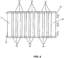
- Figure 4 shows how a multiplicity of cells according to the invention can be assembled to form a stack comprising, besides the various cells, also two terminal plates (17) and (18) whose stiffness ensures a uniform compression of all the components in the longitudinal direction.
- the lines with crosses indicate the manifolds for the passage of the gas feeds, the discharges gases and the cooling water and which are formed by the juxtaposition of the appropriate holes present on the bipolar plates and on the gasket frames, as known in the art.
- the first embodiment intends to take advantage from the mentioned capacity of the porous-type element to uniformly distribute the gases, air in particular, also in the presence of water droplets stuck inside the structure, however in operating conditions minimising the probability of percolation of liquid water toward the lower part of the cell.
- the hydration of the membrane in the lower region where air is fed is ensured by the diffusion of liquid water from the anodic compartment across the membrane.
- liquid water in the anodic compartment is made possible by the relevant flow-rate contraction undergone by pure hydrogen and to a significant extent also by the hydrogen-containing gas: such contraction determines the supersaturation of the water vapour whereof hydrogen has been enriched in the transit across the cell or which was already present in the fed hydrogen-containing gas. It follows that liquid water separates in the lower part of the cell succeeding in maintaining the membrane hydrated also when dry air is injected on the opposite side. Nevertheless, since the amount of water which condenses on the anode side is relatively modest, it is necessary that the air volumetric flow-rate be limited, particularly in conditions of maximum electrical output when the quantity of air required for the regular functioning is certainly remarkable.
- the air pressure in correspondence of the cell inlet region be higher than atmospheric, but lower than 3 bar, preferably lower than 2.5 bar, to limit the energy consumption of the compressor, as previously said.
- the reduced volumetric flow-rate if on one hand is favourable for maintaining the hydration in the critical region of the membrane, results however counterproductive since the water vapour saturation is rapidly reached.
- a sensible amount of liquid water is formed, which may negatively affect the behaviour even of a tolerant component as is the porous planar element.
- This problem can be solved by selecting a planar element whose porosity establishes a sensible pressure drop on the air flow.
- the pressure drop implies the increase of the air volumetric flow-rate with consequent enhanced capacity of vaporising liquid water.
- the capacity of vaporising water in the liquid phase may be further influenced through the exhaust air temperature, in its turn being a function of the cooling water temperature.
- Figure 5 shows the voltages of a 15 cell stack subjected to a severe electrical output cycle from 2000 A/m 2 to 10000 A/m 2 . In figure 6 the trend in time of the voltage at 2000 A/m 2 is reported.
- the cells of the stack were comprised of AISI 316 L-type stainless steel bipolar plates, internal gas distributors of nickel-chromium alloy three-dimensional reticulated type, ELAT® electrodes provided by De Nora North America, E-Tek Division, USA, Nafion® N1135 membranes provided by DuPont, USA..
- the operating conditions were: dry air fed in the lower part of the cells at 1.5 bar at 25-50°C, exhaust air discharged from the upper part of the cells at near-atmospheric pressure (pressure variation in crossing the porous planar element: about 0.5 bar), air stoichiometric excess equal to 1.7-2.4, hydrogen fed in the upper part of cells at 1.3 bar, hydrogen stoichiometric excess equal to 1.1-1.2, operating temperature 65-75°C, inlet and outlet cooling water temperature respectively 62°C and 74°C.
- the stack operation results extremely stable notwithstanding the dry air feed and the very severe operating conditions.
- the second embodiment of the invention addresses this problem ensuring a practically uniform pressure distribution on the membrane, also with modest cathode-anode pressure differentials.
- the porous internal distributor is characterised by high void volume to total volume ratio, for instance above 50%, and preferably above 70%: as a consequence, the air pressure drop across the distributor is extremely reduced, indicatively below 0.2 bar, more preferably below 0.1 bar.
- the air volumetric flow-rate is high and capable of dehydrating the membrane in the feed region where the available water is only that which diffuses across the membrane from the anodic compartment.
- This problem may be kept under control by fixing the exhaust air temperature marginally below the dew point which is a function of the ratio moles of water formed by reaction/total discharged moles of exhaust air and vapour, through the regulation of the cooling water temperature: in this way a fraction of the water formed by reaction condenses and percolates through the porous distributor to the bottom of the cell, where it keeps the membrane hydrated.
- the stack in accordance with the invention was operated with the settings employed for obtaining the data of figures 5 and 6 , the differences being the distributors consisting of nickel-chromium alloy three-dimensionally reticulated material with a void volume/total volume ratio of 75%, the feed pressure of 1.2 bar and the exhaust air outlet temperature kept around 60-65°C.
- the results obtained were fully satisfactory, with a substantial stack voltage stability also after 560 hours of operation with voltages equivalent to those indicated in figures 5 and 6 .
- the described operation requires some control instrumentation of the exhaust air outlet temperature and of the cooling water temperature.
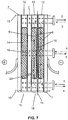
- the membrane hydration in the lower critical region in conditions of dry air feed at moderate pressure, lower than 3 bar, preferably lower than 2.5 bar and even more preferably at near-atmospheric pressure is ensured merely by means of the direct water injection as sketched in figure 7 : the bipolar plate (19) facing the cathode (9) is provided with calibrated holes (20) through which the water fed at (16) is injected into the cathodic compartment (dotted line) in the proximity of the dry air feed. Since the injected water, besides keeping the membrane hydrated, evaporates to humidify the air, it also guarantees an effective cooling making the cooling water circulation through (16) not necessary anymore.
- the flow of injected water is established in a simple fashion by means of an adjustable rotating external pump (not shown in figure 7 ).
- the exhaust air outlet temperature does not require any particular adjustment and may certainly result higher than the dew point as above defined.
- the stack of the invention consisting of 15 cells modified as indicated to adapt them to the humidifying water injection, was operated in the electrical output conditions used for obtaining the data of figures 5 and 6 , with a very satisfactory voltage stability and slightly better voltages than those collected in figures 5 and 6 . It can be supposed, without thereby limiting the invention at all, that the effectiveness of the injected water is due to the formation of a small liquid phase level in the lower part of the cells.
- This level fully hydrates the membranes and quickly humidifies the air, which is forced to bubble through it.
- the water-flow rate is adjusted as a function of the electrical output by acting on the rotation regime of the injection pump so as to obtain an equilibrium condition between amount injected and amount withdrawn in form of vaporised water and of dragged water as atomised phase.
- An operating alternative to this embodiment is characterised by a remarkable simplification of the regulations and contemplates that the fuel cell or stack, in the case of a multiplicity of cells, be provided with air feed and water injection fixed at the required value for the maximum nominal electrical output conditions: thus the lower is the electrical output, the larger are the excesses of air and water.
- the dehydrating effect of the high air flow-rates is effectively counteracted by the injection of water even in the critical air inlet region and even in conditions of reduced or nil formation of product water as occurs at low or zero electrical output.
- this kind of operation entails a higher average energy consumption for feeding the air, which can be however within acceptable limits depending on the air feeding pressure that can be particularly moderate, typically 1.2 bar, and preferably 1.1 bar: for example, in the case of a 5kW electrical power stack, the dry air flow-rate with a stoichiometric excess of 2 results to be about 16 m 3 /hour,, corresponding to an indicative power of just 0.25 kW for bringing the pressure to 1.2 bar.
- the stack of the invention operated as indicated, showed excellent performances, with a system simplicity and therefore with an operative reliability inconceivable up to now.
Landscapes
- Life Sciences & Earth Sciences (AREA)
- Engineering & Computer Science (AREA)
- Manufacturing & Machinery (AREA)
- Sustainable Development (AREA)
- Sustainable Energy (AREA)
- Chemical & Material Sciences (AREA)
- Chemical Kinetics & Catalysis (AREA)
- Electrochemistry (AREA)
- General Chemical & Material Sciences (AREA)
- Fuel Cell (AREA)
Applications Claiming Priority (2)
| Application Number | Priority Date | Filing Date | Title |
|---|---|---|---|
| IT002531A ITMI20032531A1 (it) | 2003-12-19 | 2003-12-19 | Cella a combustione a membrana alimentata in |
| PCT/EP2004/014420 WO2005060031A2 (en) | 2003-12-19 | 2004-12-17 | Membrane fuell cell countercurrent-fed with non-humidified air |
Publications (2)
| Publication Number | Publication Date |
|---|---|
| EP1695403A2 EP1695403A2 (en) | 2006-08-30 |
| EP1695403B1 true EP1695403B1 (en) | 2019-01-16 |
Family
ID=34685628
Family Applications (1)
| Application Number | Title | Priority Date | Filing Date |
|---|---|---|---|
| EP04804023.2A Expired - Lifetime EP1695403B1 (en) | 2003-12-19 | 2004-12-17 | Membrane fuell cell countercurrent-fed with non-humidified air |
Country Status (7)
| Country | Link |
|---|---|
| US (1) | US9806350B2 (it) |
| EP (1) | EP1695403B1 (it) |
| JP (1) | JP2007515759A (it) |
| CA (1) | CA2548490C (it) |
| ES (1) | ES2716763T3 (it) |
| IT (1) | ITMI20032531A1 (it) |
| WO (1) | WO2005060031A2 (it) |
Families Citing this family (7)
| Publication number | Priority date | Publication date | Assignee | Title |
|---|---|---|---|---|
| JP4940655B2 (ja) * | 2005-12-27 | 2012-05-30 | トヨタ自動車株式会社 | 燃料電池 |
| JP5011763B2 (ja) * | 2006-03-10 | 2012-08-29 | トヨタ自動車株式会社 | 燃料電池 |
| JP5361204B2 (ja) * | 2008-02-18 | 2013-12-04 | キヤノン株式会社 | 燃料電池スタック |
| US8889314B2 (en) * | 2009-01-13 | 2014-11-18 | GM Global Technology Operations LLC | Bipolar plate for a fuel cell stack |
| KR101230892B1 (ko) * | 2010-11-05 | 2013-02-07 | 현대자동차주식회사 | 연료전지용 금속다공체 |
| CN104396074B (zh) * | 2012-07-23 | 2017-05-31 | 丰田自动车株式会社 | 燃料电池系统及其运转方法 |
| CN117284650B (zh) * | 2023-11-24 | 2024-02-23 | 江苏扬子催化剂有限公司 | 一种催化剂载体加湿料仓 |
Family Cites Families (22)
| Publication number | Priority date | Publication date | Assignee | Title |
|---|---|---|---|---|
| IT1270878B (it) * | 1993-04-30 | 1997-05-13 | Permelec Spa Nora | Migliorata cella elettrochimica utilizzante membrane a scambio ionico e piatti bipolari metallici |
| JPH08255619A (ja) * | 1995-03-20 | 1996-10-01 | Matsushita Electric Ind Co Ltd | 燃料電池 |
| IT1284072B1 (it) * | 1996-06-26 | 1998-05-08 | De Nora Spa | Cella elettrochimica a membrana provvista di elettrodi a diffusione gassosa contattati da portacorrente metallici lisci e porosi a |
| JP3499090B2 (ja) * | 1996-08-07 | 2004-02-23 | 本田技研工業株式会社 | 燃料電池 |
| JP3627412B2 (ja) * | 1996-11-29 | 2005-03-09 | 東レ株式会社 | 固体高分子型燃料電池用集電体 |
| US5998054A (en) * | 1997-07-23 | 1999-12-07 | Plug Power, L.L.C. | Fuel cell membrane hydration and fluid metering |
| US6207312B1 (en) | 1998-09-18 | 2001-03-27 | Energy Partners, L.C. | Self-humidifying fuel cell |
| IT1312198B1 (it) * | 1999-04-21 | 2002-04-09 | De Nora Spa | Cella a combustibile raffreddata mediante iniezione diretta di acqualiquida |
| IT1314256B1 (it) | 1999-12-03 | 2002-12-06 | Nora Fuel Cells S P A De | Batteria di celle a combustibile a membrana polimerica. |
| US6770394B2 (en) * | 2000-02-11 | 2004-08-03 | The Texas A&M University System | Fuel cell with monolithic flow field-bipolar plate assembly and method for making and cooling a fuel cell stack |
| US20030148157A1 (en) * | 2000-04-06 | 2003-08-07 | Grasso Albert P. | Functional integration of multiple components for a fuel cell power plant |
| KR100680884B1 (ko) * | 2000-07-14 | 2007-02-08 | 프란츠 하이머 마쉬넨바우 카게 | 드릴링, 밀링 또는 리밍 공구와 같은, 회전축에 관하여회전가능한 공구용 공구홀더 |
| JP3610892B2 (ja) * | 2000-07-26 | 2005-01-19 | トヨタ自動車株式会社 | 燃料電池 |
| JP2002042833A (ja) | 2000-07-26 | 2002-02-08 | Fuji Electric Co Ltd | 固体高分子電解質型燃料電池 |
| JP2002184428A (ja) * | 2000-12-11 | 2002-06-28 | Toyota Motor Corp | 燃料電池 |
| US6627035B2 (en) * | 2001-01-24 | 2003-09-30 | Gas Technology Institute | Gas diffusion electrode manufacture and MEA fabrication |
| DE10103568A1 (de) * | 2001-01-26 | 2002-08-14 | Daimler Chrysler Ag | Verfahren zur Verbesserung des Wasserhaushalts von Brennstoffzellen |
| JP2003272666A (ja) | 2001-08-21 | 2003-09-26 | Equos Research Co Ltd | 燃料電池 |
| JP4085652B2 (ja) * | 2001-08-21 | 2008-05-14 | 株式会社エクォス・リサーチ | 燃料電池 |
| JP4344500B2 (ja) * | 2002-01-07 | 2009-10-14 | 本田技研工業株式会社 | 燃料電池 |
| DE10216953B4 (de) * | 2002-04-17 | 2006-02-23 | Daimlerchrysler Ag | Vorrichtung und Verfahren zur Versorgung einer Brennstoffzelle mit Prozessluft und deren Verwendung |
| KR100669689B1 (ko) * | 2003-03-25 | 2007-01-18 | 삼성에스디아이 주식회사 | 바이폴라판과 이를 채용하는 연료전지 |
-
2003
- 2003-12-19 IT IT002531A patent/ITMI20032531A1/it unknown
-
2004
- 2004-12-17 WO PCT/EP2004/014420 patent/WO2005060031A2/en not_active Ceased
- 2004-12-17 US US10/583,023 patent/US9806350B2/en active Active
- 2004-12-17 ES ES04804023T patent/ES2716763T3/es not_active Expired - Lifetime
- 2004-12-17 JP JP2006544361A patent/JP2007515759A/ja active Pending
- 2004-12-17 CA CA2548490A patent/CA2548490C/en not_active Expired - Lifetime
- 2004-12-17 EP EP04804023.2A patent/EP1695403B1/en not_active Expired - Lifetime
Non-Patent Citations (1)
| Title |
|---|
| None * |
Also Published As
| Publication number | Publication date |
|---|---|
| CA2548490A1 (en) | 2005-06-30 |
| WO2005060031A2 (en) | 2005-06-30 |
| WO2005060031A3 (en) | 2006-01-05 |
| ITMI20032531A1 (it) | 2005-06-20 |
| US9806350B2 (en) | 2017-10-31 |
| ES2716763T3 (es) | 2019-06-14 |
| CA2548490C (en) | 2017-10-17 |
| EP1695403A2 (en) | 2006-08-30 |
| US20070281187A1 (en) | 2007-12-06 |
| JP2007515759A (ja) | 2007-06-14 |
Similar Documents
| Publication | Publication Date | Title |
|---|---|---|
| KR100778648B1 (ko) | 고분자 막 연료 전지의 스택 | |
| Lin et al. | Effect of thickness and hydrophobic polymer content of the gas diffusion layer on electrode flooding level in a PEMFC | |
| US4826741A (en) | Ion exchange fuel cell assembly with improved water and thermal management | |
| US5952119A (en) | Fuel cell membrane humidification | |
| US4818637A (en) | Hydrogen/halogen fuel cell with improved water management system | |
| JP3382708B2 (ja) | 固体高分子電解質燃料電池用ガスセパレータ | |
| CN102163723B (zh) | 高弯曲度的扩散介质 | |
| EP1695403B1 (en) | Membrane fuell cell countercurrent-fed with non-humidified air | |
| JP5051976B2 (ja) | 電気化学発電装置及びその使用方法 | |
| EP1301956B1 (en) | Polymer fuel cell structure | |
| JP3111682B2 (ja) | 固体高分子電解質型燃料電池システム | |
| CN101395753A (zh) | 燃料电池系统 | |
| López et al. | Comparison of water management between two bipolar plate flow-field geometries in proton exchange membrane fuel cells at low-density current range | |
| JP2000277128A (ja) | 固体高分子型燃料電池 | |
| Jithesh et al. | Experimental investigation of dry feed operation in a polymer electrolyte membrane fuel cell | |
| US20090130500A1 (en) | Method of operating a fuel cell stack at low pressure and low power conditions | |
| JPWO2008050640A1 (ja) | 燃料電池 | |
| JP2004529458A (ja) | 燃料電池の水分平衡を改良する方法 | |
| US8546039B2 (en) | Solid polymer fuel cell | |
| US20090263688A1 (en) | Fuel cell | |
| Wilson et al. | Alternative flow-field and backing concepts for polymer electrolyte fuel cells | |
| CN112514124A (zh) | 加湿器、带有加湿器的燃料电池装置以及机动车 | |
| WO2004088768A2 (en) | Method for operating a membrane electrochemical generator | |
| Aman et al. | Water Management in PEM Fuel Cells | |
| CA1323905C (en) | Ion exchange fuel cell assembly with improved water and thermal management |
Legal Events
| Date | Code | Title | Description |
|---|---|---|---|
| PUAI | Public reference made under article 153(3) epc to a published international application that has entered the european phase |
Free format text: ORIGINAL CODE: 0009012 |
|
| 17P | Request for examination filed |
Effective date: 20060614 |
|
| AK | Designated contracting states |
Kind code of ref document: A2 Designated state(s): AT BE BG CH CY CZ DE DK EE ES FI FR GB GR HU IE IS IT LI LT LU MC NL PL PT RO SE SI SK TR |
|
| DAX | Request for extension of the european patent (deleted) | ||
| 17Q | First examination report despatched |
Effective date: 20080229 |
|
| STAA | Information on the status of an ep patent application or granted ep patent |
Free format text: STATUS: EXAMINATION IS IN PROGRESS |
|
| RIC1 | Information provided on ipc code assigned before grant |
Ipc: H01M 8/0258 20160101ALI20180612BHEP Ipc: H01M 8/04089 20160101ALI20180612BHEP Ipc: H01M 8/04119 20160101ALI20180612BHEP Ipc: H01M 8/023 20160101ALI20180612BHEP Ipc: H01M 8/0202 20160101AFI20180612BHEP Ipc: H01M 8/1018 20160101ALN20180612BHEP Ipc: H01M 8/04029 20160101ALI20180612BHEP Ipc: H01M 8/04291 20160101ALN20180612BHEP Ipc: H01M 8/0267 20160101ALI20180612BHEP Ipc: H01M 4/86 20060101ALN20180612BHEP |
|
| GRAP | Despatch of communication of intention to grant a patent |
Free format text: ORIGINAL CODE: EPIDOSNIGR1 |
|
| STAA | Information on the status of an ep patent application or granted ep patent |
Free format text: STATUS: GRANT OF PATENT IS INTENDED |
|
| INTG | Intention to grant announced |
Effective date: 20180725 |
|
| GRAJ | Information related to disapproval of communication of intention to grant by the applicant or resumption of examination proceedings by the epo deleted |
Free format text: ORIGINAL CODE: EPIDOSDIGR1 |
|
| STAA | Information on the status of an ep patent application or granted ep patent |
Free format text: STATUS: EXAMINATION IS IN PROGRESS |
|
| REG | Reference to a national code |
Ref country code: DE Ref legal event code: R079 Ref document number: 602004053647 Country of ref document: DE Free format text: PREVIOUS MAIN CLASS: H01M0008020000 Ipc: H01M0008020200 |
|
| GRAR | Information related to intention to grant a patent recorded |
Free format text: ORIGINAL CODE: EPIDOSNIGR71 |
|
| GRAS | Grant fee paid |
Free format text: ORIGINAL CODE: EPIDOSNIGR3 |
|
| STAA | Information on the status of an ep patent application or granted ep patent |
Free format text: STATUS: GRANT OF PATENT IS INTENDED |
|
| GRAA | (expected) grant |
Free format text: ORIGINAL CODE: 0009210 |
|
| STAA | Information on the status of an ep patent application or granted ep patent |
Free format text: STATUS: THE PATENT HAS BEEN GRANTED |
|
| INTC | Intention to grant announced (deleted) | ||
| INTG | Intention to grant announced |
Effective date: 20181203 |
|
| RIC1 | Information provided on ipc code assigned before grant |
Ipc: H01M 8/0258 20160101ALI20181130BHEP Ipc: H01M 8/04089 20160101ALI20181130BHEP Ipc: H01M 8/0202 20160101AFI20181130BHEP Ipc: H01M 8/023 20160101ALI20181130BHEP Ipc: H01M 8/04119 20160101ALI20181130BHEP Ipc: H01M 4/86 20060101ALN20181130BHEP Ipc: H01M 8/0267 20160101ALI20181130BHEP Ipc: H01M 8/04291 20160101ALN20181130BHEP Ipc: H01M 8/04029 20160101ALI20181130BHEP Ipc: H01M 8/1018 20160101ALN20181130BHEP |
|
| AK | Designated contracting states |
Kind code of ref document: B1 Designated state(s): AT BE BG CH CY CZ DE DK EE ES FI FR GB GR HU IE IS IT LI LT LU MC NL PL PT RO SE SI SK TR |
|
| REG | Reference to a national code |
Ref country code: GB Ref legal event code: FG4D |
|
| REG | Reference to a national code |
Ref country code: CH Ref legal event code: EP Ref country code: CH Ref legal event code: PK Free format text: BERICHTIGUNGEN |
|
| REG | Reference to a national code |
Ref country code: IE Ref legal event code: FG4D |
|
| RIC2 | Information provided on ipc code assigned after grant |
Ipc: H01M 4/86 20060101ALN20181130BHEP Ipc: H01M 8/04029 20160101ALI20181130BHEP Ipc: H01M 8/04291 20160101ALN20181130BHEP Ipc: H01M 8/0202 20160101AFI20181130BHEP Ipc: H01M 8/023 20160101ALI20181130BHEP Ipc: H01M 8/0267 20160101ALI20181130BHEP Ipc: H01M 8/1018 20160101ALN20181130BHEP Ipc: H01M 8/0258 20160101ALI20181130BHEP Ipc: H01M 8/04089 20160101ALI20181130BHEP Ipc: H01M 8/04119 20160101ALI20181130BHEP |
|
| REG | Reference to a national code |
Ref country code: DE Ref legal event code: R096 Ref document number: 602004053647 Country of ref document: DE |
|
| REG | Reference to a national code |
Ref country code: AT Ref legal event code: REF Ref document number: 1090400 Country of ref document: AT Kind code of ref document: T Effective date: 20190215 |
|
| REG | Reference to a national code |
Ref country code: DE Ref legal event code: R082 Ref document number: 602004053647 Country of ref document: DE Representative=s name: REITSTOETTER KINZEBACH, DE Ref country code: DE Ref legal event code: R081 Ref document number: 602004053647 Country of ref document: DE Owner name: NUVERA FUEL CELLS, LLC, BILLERICA, US Free format text: FORMER OWNER: NUVERA FUEL CELLS EUROPE S.R.L., MAILAND/MILANO, IT |
|
| RAP2 | Party data changed (patent owner data changed or rights of a patent transferred) |
Owner name: NUVERA FUEL CELLS, LLC |
|
| REG | Reference to a national code |
Ref country code: GB Ref legal event code: 732E Free format text: REGISTERED BETWEEN 20190404 AND 20190410 |
|
| REG | Reference to a national code |
Ref country code: NL Ref legal event code: MP Effective date: 20190116 |
|
| REG | Reference to a national code |
Ref country code: LT Ref legal event code: MG4D |
|
| REG | Reference to a national code |
Ref country code: ES Ref legal event code: FG2A Ref document number: 2716763 Country of ref document: ES Kind code of ref document: T3 Effective date: 20190614 |
|
| PG25 | Lapsed in a contracting state [announced via postgrant information from national office to epo] |
Ref country code: NL Free format text: LAPSE BECAUSE OF FAILURE TO SUBMIT A TRANSLATION OF THE DESCRIPTION OR TO PAY THE FEE WITHIN THE PRESCRIBED TIME-LIMIT Effective date: 20190116 |
|
| REG | Reference to a national code |
Ref country code: AT Ref legal event code: MK05 Ref document number: 1090400 Country of ref document: AT Kind code of ref document: T Effective date: 20190116 |
|
| PG25 | Lapsed in a contracting state [announced via postgrant information from national office to epo] |
Ref country code: LT Free format text: LAPSE BECAUSE OF FAILURE TO SUBMIT A TRANSLATION OF THE DESCRIPTION OR TO PAY THE FEE WITHIN THE PRESCRIBED TIME-LIMIT Effective date: 20190116 Ref country code: PL Free format text: LAPSE BECAUSE OF FAILURE TO SUBMIT A TRANSLATION OF THE DESCRIPTION OR TO PAY THE FEE WITHIN THE PRESCRIBED TIME-LIMIT Effective date: 20190116 Ref country code: PT Free format text: LAPSE BECAUSE OF FAILURE TO SUBMIT A TRANSLATION OF THE DESCRIPTION OR TO PAY THE FEE WITHIN THE PRESCRIBED TIME-LIMIT Effective date: 20190516 Ref country code: SE Free format text: LAPSE BECAUSE OF FAILURE TO SUBMIT A TRANSLATION OF THE DESCRIPTION OR TO PAY THE FEE WITHIN THE PRESCRIBED TIME-LIMIT Effective date: 20190116 Ref country code: FI Free format text: LAPSE BECAUSE OF FAILURE TO SUBMIT A TRANSLATION OF THE DESCRIPTION OR TO PAY THE FEE WITHIN THE PRESCRIBED TIME-LIMIT Effective date: 20190116 |
|
| PG25 | Lapsed in a contracting state [announced via postgrant information from national office to epo] |
Ref country code: GR Free format text: LAPSE BECAUSE OF FAILURE TO SUBMIT A TRANSLATION OF THE DESCRIPTION OR TO PAY THE FEE WITHIN THE PRESCRIBED TIME-LIMIT Effective date: 20190417 Ref country code: IS Free format text: LAPSE BECAUSE OF FAILURE TO SUBMIT A TRANSLATION OF THE DESCRIPTION OR TO PAY THE FEE WITHIN THE PRESCRIBED TIME-LIMIT Effective date: 20190516 Ref country code: BG Free format text: LAPSE BECAUSE OF FAILURE TO SUBMIT A TRANSLATION OF THE DESCRIPTION OR TO PAY THE FEE WITHIN THE PRESCRIBED TIME-LIMIT Effective date: 20190416 |
|
| REG | Reference to a national code |
Ref country code: DE Ref legal event code: R097 Ref document number: 602004053647 Country of ref document: DE |
|
| PG25 | Lapsed in a contracting state [announced via postgrant information from national office to epo] |
Ref country code: SK Free format text: LAPSE BECAUSE OF FAILURE TO SUBMIT A TRANSLATION OF THE DESCRIPTION OR TO PAY THE FEE WITHIN THE PRESCRIBED TIME-LIMIT Effective date: 20190116 Ref country code: DK Free format text: LAPSE BECAUSE OF FAILURE TO SUBMIT A TRANSLATION OF THE DESCRIPTION OR TO PAY THE FEE WITHIN THE PRESCRIBED TIME-LIMIT Effective date: 20190116 Ref country code: CZ Free format text: LAPSE BECAUSE OF FAILURE TO SUBMIT A TRANSLATION OF THE DESCRIPTION OR TO PAY THE FEE WITHIN THE PRESCRIBED TIME-LIMIT Effective date: 20190116 Ref country code: RO Free format text: LAPSE BECAUSE OF FAILURE TO SUBMIT A TRANSLATION OF THE DESCRIPTION OR TO PAY THE FEE WITHIN THE PRESCRIBED TIME-LIMIT Effective date: 20190116 Ref country code: EE Free format text: LAPSE BECAUSE OF FAILURE TO SUBMIT A TRANSLATION OF THE DESCRIPTION OR TO PAY THE FEE WITHIN THE PRESCRIBED TIME-LIMIT Effective date: 20190116 Ref country code: AT Free format text: LAPSE BECAUSE OF FAILURE TO SUBMIT A TRANSLATION OF THE DESCRIPTION OR TO PAY THE FEE WITHIN THE PRESCRIBED TIME-LIMIT Effective date: 20190116 |
|
| PLBE | No opposition filed within time limit |
Free format text: ORIGINAL CODE: 0009261 |
|
| STAA | Information on the status of an ep patent application or granted ep patent |
Free format text: STATUS: NO OPPOSITION FILED WITHIN TIME LIMIT |
|
| 26N | No opposition filed |
Effective date: 20191017 |
|
| PG25 | Lapsed in a contracting state [announced via postgrant information from national office to epo] |
Ref country code: SI Free format text: LAPSE BECAUSE OF FAILURE TO SUBMIT A TRANSLATION OF THE DESCRIPTION OR TO PAY THE FEE WITHIN THE PRESCRIBED TIME-LIMIT Effective date: 20190116 |
|
| PG25 | Lapsed in a contracting state [announced via postgrant information from national office to epo] |
Ref country code: TR Free format text: LAPSE BECAUSE OF FAILURE TO SUBMIT A TRANSLATION OF THE DESCRIPTION OR TO PAY THE FEE WITHIN THE PRESCRIBED TIME-LIMIT Effective date: 20190116 |
|
| REG | Reference to a national code |
Ref country code: CH Ref legal event code: PL |
|
| REG | Reference to a national code |
Ref country code: BE Ref legal event code: MM Effective date: 20191231 |
|
| PG25 | Lapsed in a contracting state [announced via postgrant information from national office to epo] |
Ref country code: MC Free format text: LAPSE BECAUSE OF FAILURE TO SUBMIT A TRANSLATION OF THE DESCRIPTION OR TO PAY THE FEE WITHIN THE PRESCRIBED TIME-LIMIT Effective date: 20190116 |
|
| PG25 | Lapsed in a contracting state [announced via postgrant information from national office to epo] |
Ref country code: LU Free format text: LAPSE BECAUSE OF NON-PAYMENT OF DUE FEES Effective date: 20191217 Ref country code: IE Free format text: LAPSE BECAUSE OF NON-PAYMENT OF DUE FEES Effective date: 20191217 |
|
| PG25 | Lapsed in a contracting state [announced via postgrant information from national office to epo] |
Ref country code: CH Free format text: LAPSE BECAUSE OF NON-PAYMENT OF DUE FEES Effective date: 20191231 Ref country code: LI Free format text: LAPSE BECAUSE OF NON-PAYMENT OF DUE FEES Effective date: 20191231 Ref country code: BE Free format text: LAPSE BECAUSE OF NON-PAYMENT OF DUE FEES Effective date: 20191231 |
|
| PG25 | Lapsed in a contracting state [announced via postgrant information from national office to epo] |
Ref country code: CY Free format text: LAPSE BECAUSE OF FAILURE TO SUBMIT A TRANSLATION OF THE DESCRIPTION OR TO PAY THE FEE WITHIN THE PRESCRIBED TIME-LIMIT Effective date: 20190116 |
|
| PG25 | Lapsed in a contracting state [announced via postgrant information from national office to epo] |
Ref country code: HU Free format text: LAPSE BECAUSE OF FAILURE TO SUBMIT A TRANSLATION OF THE DESCRIPTION OR TO PAY THE FEE WITHIN THE PRESCRIBED TIME-LIMIT; INVALID AB INITIO Effective date: 20041217 |
|
| PGFP | Annual fee paid to national office [announced via postgrant information from national office to epo] |
Ref country code: GB Payment date: 20231106 Year of fee payment: 20 |
|
| PGFP | Annual fee paid to national office [announced via postgrant information from national office to epo] |
Ref country code: IT Payment date: 20231019 Year of fee payment: 20 Ref country code: FR Payment date: 20231107 Year of fee payment: 20 Ref country code: DE Payment date: 20231106 Year of fee payment: 20 |
|
| PGFP | Annual fee paid to national office [announced via postgrant information from national office to epo] |
Ref country code: ES Payment date: 20240109 Year of fee payment: 20 |
|
| REG | Reference to a national code |
Ref country code: DE Ref legal event code: R071 Ref document number: 602004053647 Country of ref document: DE |
|
| REG | Reference to a national code |
Ref country code: ES Ref legal event code: FD2A Effective date: 20241230 |
|
| REG | Reference to a national code |
Ref country code: GB Ref legal event code: PE20 Expiry date: 20241216 |
|
| PG25 | Lapsed in a contracting state [announced via postgrant information from national office to epo] |
Ref country code: GB Free format text: LAPSE BECAUSE OF EXPIRATION OF PROTECTION Effective date: 20241216 |
|
| PG25 | Lapsed in a contracting state [announced via postgrant information from national office to epo] |
Ref country code: ES Free format text: LAPSE BECAUSE OF EXPIRATION OF PROTECTION Effective date: 20241218 |
|
| PG25 | Lapsed in a contracting state [announced via postgrant information from national office to epo] |
Ref country code: GB Free format text: LAPSE BECAUSE OF EXPIRATION OF PROTECTION Effective date: 20241216 Ref country code: ES Free format text: LAPSE BECAUSE OF EXPIRATION OF PROTECTION Effective date: 20241218 |