EP1686246B1 - Silencieux pour système d'échappement - Google Patents
Silencieux pour système d'échappement Download PDFInfo
- Publication number
- EP1686246B1 EP1686246B1 EP05023124A EP05023124A EP1686246B1 EP 1686246 B1 EP1686246 B1 EP 1686246B1 EP 05023124 A EP05023124 A EP 05023124A EP 05023124 A EP05023124 A EP 05023124A EP 1686246 B1 EP1686246 B1 EP 1686246B1
- Authority
- EP
- European Patent Office
- Prior art keywords
- silencer
- muffler
- flow line
- exhaust
- housing
- Prior art date
- Legal status (The legal status is an assumption and is not a legal conclusion. Google has not performed a legal analysis and makes no representation as to the accuracy of the status listed.)
- Expired - Fee Related
Links
Images
Classifications
-
- F—MECHANICAL ENGINEERING; LIGHTING; HEATING; WEAPONS; BLASTING
- F01—MACHINES OR ENGINES IN GENERAL; ENGINE PLANTS IN GENERAL; STEAM ENGINES
- F01N—GAS-FLOW SILENCERS OR EXHAUST APPARATUS FOR MACHINES OR ENGINES IN GENERAL; GAS-FLOW SILENCERS OR EXHAUST APPARATUS FOR INTERNAL COMBUSTION ENGINES
- F01N1/00—Silencing apparatus characterised by method of silencing
- F01N1/16—Silencing apparatus characterised by method of silencing by using movable parts
- F01N1/166—Silencing apparatus characterised by method of silencing by using movable parts for changing gas flow path through the silencer or for adjusting the dimensions of a chamber or a pipe
-
- F—MECHANICAL ENGINEERING; LIGHTING; HEATING; WEAPONS; BLASTING
- F01—MACHINES OR ENGINES IN GENERAL; ENGINE PLANTS IN GENERAL; STEAM ENGINES
- F01N—GAS-FLOW SILENCERS OR EXHAUST APPARATUS FOR MACHINES OR ENGINES IN GENERAL; GAS-FLOW SILENCERS OR EXHAUST APPARATUS FOR INTERNAL COMBUSTION ENGINES
- F01N1/00—Silencing apparatus characterised by method of silencing
- F01N1/003—Silencing apparatus characterised by method of silencing by using dead chambers communicating with gas flow passages
- F01N1/006—Silencing apparatus characterised by method of silencing by using dead chambers communicating with gas flow passages comprising at least one perforated tube extending from inlet to outlet of the silencer
-
- F—MECHANICAL ENGINEERING; LIGHTING; HEATING; WEAPONS; BLASTING
- F01—MACHINES OR ENGINES IN GENERAL; ENGINE PLANTS IN GENERAL; STEAM ENGINES
- F01N—GAS-FLOW SILENCERS OR EXHAUST APPARATUS FOR MACHINES OR ENGINES IN GENERAL; GAS-FLOW SILENCERS OR EXHAUST APPARATUS FOR INTERNAL COMBUSTION ENGINES
- F01N1/00—Silencing apparatus characterised by method of silencing
- F01N1/08—Silencing apparatus characterised by method of silencing by reducing exhaust energy by throttling or whirling
- F01N1/083—Silencing apparatus characterised by method of silencing by reducing exhaust energy by throttling or whirling using transversal baffles defining a tortuous path for the gases or successively throttling gas flow
-
- F—MECHANICAL ENGINEERING; LIGHTING; HEATING; WEAPONS; BLASTING
- F01—MACHINES OR ENGINES IN GENERAL; ENGINE PLANTS IN GENERAL; STEAM ENGINES
- F01N—GAS-FLOW SILENCERS OR EXHAUST APPARATUS FOR MACHINES OR ENGINES IN GENERAL; GAS-FLOW SILENCERS OR EXHAUST APPARATUS FOR INTERNAL COMBUSTION ENGINES
- F01N1/00—Silencing apparatus characterised by method of silencing
- F01N1/08—Silencing apparatus characterised by method of silencing by reducing exhaust energy by throttling or whirling
- F01N1/084—Silencing apparatus characterised by method of silencing by reducing exhaust energy by throttling or whirling the gases flowing through the silencer two or more times longitudinally in opposite directions, e.g. using parallel or concentric tubes
-
- F—MECHANICAL ENGINEERING; LIGHTING; HEATING; WEAPONS; BLASTING
- F01—MACHINES OR ENGINES IN GENERAL; ENGINE PLANTS IN GENERAL; STEAM ENGINES
- F01N—GAS-FLOW SILENCERS OR EXHAUST APPARATUS FOR MACHINES OR ENGINES IN GENERAL; GAS-FLOW SILENCERS OR EXHAUST APPARATUS FOR INTERNAL COMBUSTION ENGINES
- F01N13/00—Exhaust or silencing apparatus characterised by constructional features ; Exhaust or silencing apparatus, or parts thereof, having pertinent characteristics not provided for in, or of interest apart from, groups F01N1/00 - F01N5/00, F01N9/00, F01N11/00
- F01N13/18—Construction facilitating manufacture, assembly, or disassembly
- F01N13/1888—Construction facilitating manufacture, assembly, or disassembly the housing of the assembly consisting of two or more parts, e.g. two half-shells
- F01N13/1894—Construction facilitating manufacture, assembly, or disassembly the housing of the assembly consisting of two or more parts, e.g. two half-shells the parts being assembled in longitudinal direction
-
- F—MECHANICAL ENGINEERING; LIGHTING; HEATING; WEAPONS; BLASTING
- F01—MACHINES OR ENGINES IN GENERAL; ENGINE PLANTS IN GENERAL; STEAM ENGINES
- F01N—GAS-FLOW SILENCERS OR EXHAUST APPARATUS FOR MACHINES OR ENGINES IN GENERAL; GAS-FLOW SILENCERS OR EXHAUST APPARATUS FOR INTERNAL COMBUSTION ENGINES
- F01N3/00—Exhaust or silencing apparatus having means for purifying, rendering innocuous, or otherwise treating exhaust
- F01N3/08—Exhaust or silencing apparatus having means for purifying, rendering innocuous, or otherwise treating exhaust for rendering innocuous
- F01N3/10—Exhaust or silencing apparatus having means for purifying, rendering innocuous, or otherwise treating exhaust for rendering innocuous by thermal or catalytic conversion of noxious components of exhaust
- F01N3/24—Exhaust or silencing apparatus having means for purifying, rendering innocuous, or otherwise treating exhaust for rendering innocuous by thermal or catalytic conversion of noxious components of exhaust characterised by constructional aspects of converting apparatus
- F01N3/28—Construction of catalytic reactors
- F01N3/2882—Catalytic reactors combined or associated with other devices, e.g. exhaust silencers or other exhaust purification devices
- F01N3/2885—Catalytic reactors combined or associated with other devices, e.g. exhaust silencers or other exhaust purification devices with exhaust silencers in a single housing
-
- Y—GENERAL TAGGING OF NEW TECHNOLOGICAL DEVELOPMENTS; GENERAL TAGGING OF CROSS-SECTIONAL TECHNOLOGIES SPANNING OVER SEVERAL SECTIONS OF THE IPC; TECHNICAL SUBJECTS COVERED BY FORMER USPC CROSS-REFERENCE ART COLLECTIONS [XRACs] AND DIGESTS
- Y02—TECHNOLOGIES OR APPLICATIONS FOR MITIGATION OR ADAPTATION AGAINST CLIMATE CHANGE
- Y02A—TECHNOLOGIES FOR ADAPTATION TO CLIMATE CHANGE
- Y02A50/00—TECHNOLOGIES FOR ADAPTATION TO CLIMATE CHANGE in human health protection, e.g. against extreme weather
- Y02A50/20—Air quality improvement or preservation, e.g. vehicle emission control or emission reduction by using catalytic converters
Definitions
- the invention is based on a silencer for an exhaust system of an internal combustion engine of a motor vehicle, according to the preamble of claim 1.
- a muffler for an exhaust system of an internal combustion engine is known.
- the muffler consists of a catalyst and a downstream actual muffler, in which a first and second flow line are arranged.
- the muffler on the catalyst has an exhaust gas inlet and on the muffler an exhaust gas outlet.
- One of the flow lines namely the first flow line, passes through the muffler completely and opens into an exhaust gas end pipe, which lies downstream of the muffler.
- the second flow line which only partially passes through the muffler, and the first flow line is located within the muffler an overflow.
- a branching element is provided, which is connected via the catalyst to the exhaust gas inlet.
- a shut-off is provided between the catalyst, which has a housing, and the muffler is in the first flow line, a shut-off, which is thus also upstream of the muffler.
- a silencer of an exhaust system is from the DE 38 35 079 A1 known.
- Fig. 5 in this DE 38 35 079 A1 shows this muffler, which has a single exhaust inlet and two exhaust tailpipes.
- the muffler is completely penetrated by a first flow line, which has both the single exhaust inlet and one of the exhaust tailpipes.
- a shut-off means for shutting off and releasing the first flow line is arranged in the exhaust gas end pipe, which lies downstream of the muffler.
- the shut-off is designed as a so-called exhaust flap, which can be operated via a pivot mechanism.
- Within the Silencer is arranged a second flow line, which is led out with the second exhaust pipe from the muffler.
- the shut-off means If the shut-off means is open, the exhaust gas stream of the internal combustion engine enters via the exhaust gas inlet and can be guided unhindered via the first flow line to the exhaust gas end pipe.
- the shut-off means When the shut-off means is closed, the exhaust gas exits via a perforation in the first flow line arranged inside the silencer, penetrates a nozzle arranged in a dividing wall and enters the second flow path via a perforation and can thus be transported away via the second exhaust end pipe.
- the two perforations and arranged in the partition wall thus form a lying within the muffler Kochströmweg between the first and the second flow line.
- the object of the invention is to optimize a silencer of the type mentioned in terms of its function and integration into an exhaust system.
- the advantages achieved by the invention are to be seen in the fact that the arrangement of the shut-off upstream of the housing of the muffler, but downstream of a catalyst housing, a favorable effect on the exiting from the exhaust tailpipe exhaust noise is possible. It has been shown that a clear sound difference can be achieved by the inventive arrangement of the shut-off device in front of the muffler when the exhaust gas produced by the internal combustion engine is guided over the first or second flow line.
- the silencer according to the invention can also be integrated into conventional exhaust systems and, if appropriate, retrofitted into an existing exhaust system without shut-off means.
- the catalyst housing has a front plate which forms the branching element.
- the front plate branching openings, to which connect the first and second flow line.
- the catalyst housing is fastened directly to the muffler, whereby between the catalyst housing and the muffler otherwise provided exhaust pipes can be omitted, wherein the catalyst housing is at least partially within the muffler.
- the blocking means is outside the muffler. This allows a simple connection of the shut-off with a designated drive.
- the muffler has a cutout in which the bypass section extends with the blocking means. Compared with a conventional silencer without shut-off means, no enlarged installation space is therefore necessary in the silencer according to the invention.
- the overflow path has a damping device, as stated in claim 3, the sound of the muffler will continue to differ when the blocking means are open or closed.
- the damping device have a perforated partition, which is disposed within the muffler.
- a particularly preferred embodiment of the overflow is specified in claim 5. It is advantageous that when the shut-off means a limited by the first partition chamber with a volume via the inlet to the first flow line is coupled, which affects the sound of the muffler with open shut-off favorable.
- the second partition wall can support the first and second flow line within the muffler.
- another chamber can be provided within the muffler, which is coupled with its volume to the first chamber, which favorably influences the damping of the noise of the exhaust gas.
- the muffler according to the invention can be advantageously connected to a secondary exhaust outlet, which can also be provided for a conventional muffler without shut-off.
- a modular exhaust system can be provided in which the silencer with shut-off can be easily replaced with a silencer with shut-off and vice versa.
- the modular design is further developed if, according to claim 9, the catalyst housing, the muffler with the two flow lines, the Exhaust tailpipe and the shut-off form a preassembled unit that can be used in the motor vehicle with the exhaust system.
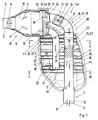
- Fig. 1 shows a longitudinal section of a muffler 1 of an otherwise not shown exhaust system for an internal combustion engine of a motor vehicle.
- the exhaust system is designed with two columns for the internal combustion engine, which may for example have two cylinder banks. Accordingly, the exhaust system for each cylinder bank such a muffler 1.
- a wiring harness not shown here, which is connected in a known manner, optionally with the interposition of a so-called pre-catalyst with the internal combustion engine.
- the muffler 1 has on the output side a single exhaust end pipe 3, which optionally leads to the other exhaust end of the other muffler exhaust system to an exhaust outlet not shown here at the rear of the vehicle.
- the exhaust end pipe 3 has an end pipe opening 4 and the exhaust gas inlet 2 has an inlet opening 5. Consequently, within the muffler 1, a flow direction for the exhaust gas, which is characterized by downstream arrows 6 results.
- the muffler 1 which has a muffler housing 7, in which a first and second flow line 8 and 9 a first and second flow path 10 and 11 is formed for the inlet opening 5 entering the exhaust gas.
- the first and second flow paths 8 and 9 are each provided with a plurality of arrows with the corresponding reference numerals 10 and 11.
- an overflow path 12 is formed between the first and second flow lines 8 and 9 and between the first and second flow paths 10 and 11, respectively, which allows exhaust gas leaving the second flow line 9 to flow into the first flow path 8 within the muffler 1 to initiate.
- the first flow line 8 passes through the muffler 1 completely and ends outside the muffler 1 with the exhaust end 3.
- a shut-off 13 with a movable valve body, in particular in the form of a movable flap 14, arranged, which shut-off 13, the first flow line Shut off 8 and release for the first flow path 10.
- the shut-off means 13, for example, a not shown here drive is associated with the flap 14 in the in Fig. 1 shown open position OT for releasing and in a closed position, not shown, for shutting off the first flow line 8 can move.
- the muffler 1 upstream ie in the opposite direction to the arrow 6, the muffler 1 is a catalyst 15 upstream with a arranged in a catalyst housing 16 exhaust treatment insert 15 ', which catalyst 15 is partially integrated with its catalyst housing 16 in the muffler housing 7.
- the second flow line 9 is arranged, which ends with an orifice 17 within the muffler housing 7, so that the exhaust gas into the muffler housing 7, via the overflow 12 into the first Flow flow line 8 and finally can flow to the exhaust pipe end 3.
- the first partition 18 is located upstream of the mouth 17, so that within the muffler housing 7, a first chamber 19 is bounded by a first side 20 of the partition 18.
- a second chamber 22 is formed within the muffler housing 7.
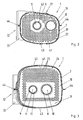
- the first partition wall 18 At least one opening, but preferably a plurality of opening 23 comprehensive perforation 24, as shown in the cross section Fig. 3 shows, are provided in the rest of the same parts with the same reference numerals.
- the inlet 25 is located within the second chamber 22 and on the second side 21 of the first partition wall 18.
- the inlet 25 is formed by a perforation 27 or perforation having a plurality of openings 28 penetrating the jacket 26 of the first flow line 8.
- a damping device 29 for the exhaust gas which has at least the perforated first partition wall 18. If the inlet 25 causes an attenuation of the exhaust gas by means of a corresponding configuration, then the inlet 25 may be assigned to the damping device 29, if appropriate.
- this inlet 25 serves to introduce the exhaust gas from the second flow path 11 into the first flow path 10 when the shut-off means 13 shuts off the first flow line 8, and on the other hand for coupling a damper volume (second chamber 22) for the first flow path 10 when the shut-off means 13 releases the first flow line 8, or the flap 14 is in the open position OT.
- a branching element 30 downstream of the exhaust gas inlet 2 is arranged downstream of both the first and second flow lines 8 and 9 9 is connected.
- the branching element 30 is part of the catalyst housing 16 and preferably forms its front plate 31, which - due to the partial integration of the catalyst 15 in the muffler 1 - within the muffler housing. 7 comes to rest and at the same time forms a wall of the muffler housing 7. In the embodiment shown, the catalyst 15 is thus fastened with its housing 16 directly to the muffler 1.
- the muffler housing 7 has a receiving channel 32, which is formed by a surrounding the catalyst housing 16 flange 33.
- the end plate 31 has two corresponding branching openings 34 and 35, in each of which the associated first and second flow line 8 and 9 are used.
- the branch opening 35 lies within the muffler housing 7 and the branch opening 34 breaks through the muffler housing 7 in the region of a housing cutout 36 of the muffler housing 7.
- the first flow line 8 extends with a bent bypass section 37 which thus lies outside the muffler housing 7 and in which the blocking means 13 is arranged.
- bypass section 37 extends within an approximately quarter-circular, imaginary edge contour 38 (dashed lines) of the muffler housing 7. With the bypass section 37 and an adjoining pipe section 37 'of the first flow line 8, the damping device 29 is bypassed.
- a second partition wall 39 has - as the first partition 18 - at least one opening, but preferably a plurality of openings 23 comprehensive perforation 24, whereby the volume of the third chamber 40 can act as a damping volume for the second flow path 11.
- the muffler housing 7 is composed of two shell-like housing parts 42 and 43, each having an outwardly bent edge strips 44, where they are firmly connected to each other. After the two housing parts 42 and 43 are assembled, so the silencer housing 7 is closed, there is a preassembled unit 45, the catalyst 15 with its housing 16, the muffler 1 with the two flow lines 8 and 9, the exhaust end pipe 3, the exhaust inlet 2 and the blocking means 13 includes.
- the assembly 45 can therefore be used as a module in the exhaust system of the motor vehicle.
- the branching element 30 or the end plate 31 of the catalyst housing 16 has a circumferential collar 46, which may be embodied integrally with the end plate 31, so that the branching element is realized cup-shaped.
- the collar 46 may be partially within the catalyst housing 16, ie plugged therein.
- the branching opening 35 could thus alternatively be arranged laterally on the branching element 30 and face the second dividing wall 39, which is not shown in the figures, however.
- the other branch opening 34 could therefore be approximately go out centrally from the end plate 31;
- a perforation could be formed in the collar 46 or in the portion 47 of the catalyst housing 16 located inside the muffler housing 7 in a modification which is not shown. This perforation could be introduced only partially or over the entire circumference of the collar 46 or section 47.
- the inlet 25 embodied as a perforation 27 in the first flow line 8 can in one embodiment be realized as a circulating separating cut (not shown) in the jacket 26, so that the flow line 8 is split between the first and second dividing wall 18, 39 and has two pipe ends the flow line 8 are spaced apart.
- the downstream tube end could be widened in a funnel shape.
- the distance between the two pipe ends to each other for example, be 10 mm to 30 mm.
Landscapes
- Engineering & Computer Science (AREA)
- Chemical & Material Sciences (AREA)
- Combustion & Propulsion (AREA)
- Mechanical Engineering (AREA)
- General Engineering & Computer Science (AREA)
- Chemical Kinetics & Catalysis (AREA)
- Health & Medical Sciences (AREA)
- Toxicology (AREA)
- Exhaust Silencers (AREA)
- Exhaust Gas After Treatment (AREA)
- Exhaust Gas Treatment By Means Of Catalyst (AREA)
Claims (9)
- Silencieux (1) pour un système de gaz d'échappement d'un moteur à combustion interne d'un véhicule automobile, avec une entrée de gaz d'échappement (2), avec une première conduite d'écoulement (8) disposée à l'intérieur du silencieux et traversant celui-ci entièrement, dans laquelle est disposé un élément de fermeture (13) pour la fermer et la libérer, avec un tube final à gaz d'échappement (3), qui est situé en aval du silencieux (1) et qui est raccordé à la première conduite d'écoulement (8), avec une deuxième conduite d'écoulement (9) qui traverse partiellement le silencieux, avec un chemin de trop-plein (12) situé à l'intérieur du silencieux entre la première et la deuxième conduites d'écoulement, dans lequel la première et la deuxième conduites d'écoulement (8, 9) sont raccordées à l'entrée de gaz d'échappement (2) au moyen d'un élément de branchement (30), un boîtier de catalyseur (16) est disposé entre l'entrée de gaz d'échappement (2) et l'élément de branchement (30), et le moyen de fermeture (13) est disposé dans la première conduite d'écoulement (8) en amont du silencieux (1) mais en aval du boîtier de catalyseur (16), caractérisé en ce que le boîtier de catalyseur (16) présente une plaque frontale avec des ouvertures de branchement (34, 35), qui forme l'élément de branchement (30), en ce que le boîtier de catalyseur (16) est fixé directement sur le silencieux (1), en ce que le boîtier de catalyseur (16) est situé au moins partiellement à l'intérieur du silencieux (1), en ce que la première conduite d'écoulement (8) s'étend avec au moins une section dé dérivation (37) à l'extérieur du silencieux (1), en ce que le moyen de fermeture (13) est disposé dans la section de dérivation (37), en ce que le boîtier (7) du silencieux (1) présente une découpe de boîtier (36) et en ce que la section de dérivation (37) s'étend à l'intérieur de cette découpe de boîtier (36).
- Silencieux selon la revendication 1, caractérisé en ce qu'au moins la plaque frontale (31) est située à l'intérieur du silencieux (1).
- Silencieux selon la revendication 1, caractérisé en ce que le chemin de trop-plein (12) présente un dispositif d'amortissement (29).
- Silencieux selon la revendication 3, caractérisé en ce que le dispositif d'amortissement (29) comporte une première paroi de séparation perforée (18) disposée à l'intérieur du silencieux (1).
- Silencieux selon les revendications 1 et 4, caractérisé en ce que la deuxième conduite d'écoulement (9) débouche dans le silencieux (1) sur un premier côté (20) de la paroi de séparation (18) (embouchure 17) et en ce que la première conduite d'écoulement (8) présente, à l'intérieur du silencieux (1), une entrée (25) qui est située sur un deuxième côté (21) de la paroi de séparation (18).
- Silencieux selon les revendications 1 et 4 ou 5, caractérisé en ce qu'une deuxième paroi de séparation (39) est disposée à l'intérieur du silencieux (1) en amont de la première paroi de séparation (18), et est traversée par la première et par la deuxième conduites d'écoulement (8, 9).
- Silencieux selon la revendication 6, caractérisé en ce que la deuxième paroi de séparation (39) est perforée et est disposée en amont de l'entrée (25) de la première conduite d'écoulement (8).
- Silencieux selon la revendication 1, caractérisé en ce qu'un seul tube final à gaz d'échappement (3) est mené hors du silencieux (1).
- Silencieux selon l'une quelconque des revendications précédentes, caractérisé en ce que le boîtier de catalyseur (16), le silencieux (1) avec les deux conduites d'écoulement (8, 9), le tube final à gaz d'échappement (3) et le moyen de fermeture (13) forment une unité de construction pré-assemblée (45), qui peut être utilisée dans le véhicule automobile.
Applications Claiming Priority (1)
| Application Number | Priority Date | Filing Date | Title |
|---|---|---|---|
| DE102005003582A DE102005003582A1 (de) | 2005-01-26 | 2005-01-26 | Schalldämpfer für eine Abgasanlage |
Publications (3)
| Publication Number | Publication Date |
|---|---|
| EP1686246A2 EP1686246A2 (fr) | 2006-08-02 |
| EP1686246A3 EP1686246A3 (fr) | 2009-02-25 |
| EP1686246B1 true EP1686246B1 (fr) | 2012-04-11 |
Family
ID=36096778
Family Applications (1)
| Application Number | Title | Priority Date | Filing Date |
|---|---|---|---|
| EP05023124A Expired - Fee Related EP1686246B1 (fr) | 2005-01-26 | 2005-10-24 | Silencieux pour système d'échappement |
Country Status (4)
| Country | Link |
|---|---|
| US (1) | US7438157B2 (fr) |
| EP (1) | EP1686246B1 (fr) |
| JP (1) | JP4249746B2 (fr) |
| DE (1) | DE102005003582A1 (fr) |
Cited By (3)
| Publication number | Priority date | Publication date | Assignee | Title |
|---|---|---|---|---|
| DE102014118633A1 (de) | 2014-12-15 | 2016-06-16 | Dr. Ing. H.C. F. Porsche Aktiengesellschaft | Abgasanlage eines Kraftfahrzeugs und Kraftfahrzeug |
| DE102015007767A1 (de) | 2015-06-18 | 2016-12-22 | Dr. Ing. H.C. F. Porsche Ag | Schalldämpfer für eine Abgasanlage eines Kraftfahrzeugs, Abgasanlage und Kraftfahrzeug |
| EP3910170A1 (fr) * | 2016-11-04 | 2021-11-17 | PIAGGIO & C. S.p.A. | Silencieux pour véhicules à moteur |
Families Citing this family (19)
| Publication number | Priority date | Publication date | Assignee | Title |
|---|---|---|---|---|
| DE10346479A1 (de) * | 2003-10-02 | 2005-05-12 | Bayerische Motoren Werke Ag | Abgasanlage für eine Brennkraftmaschine |
| DE102005041692A1 (de) * | 2005-09-01 | 2007-03-15 | J. Eberspächer GmbH & Co. KG | Schalldämpfer für eine Abgasanlage |
| DE102006020155A1 (de) * | 2005-12-15 | 2007-06-21 | Friedrich Boysen Gmbh & Co. Kg | Abgasanlage für Brennkraftmaschinen |
| DE102007026811A1 (de) * | 2007-06-06 | 2008-12-11 | J. Eberspächer GmbH & Co. KG | Schalldämpfer |
| JP5912605B2 (ja) * | 2012-02-03 | 2016-04-27 | 本田技研工業株式会社 | 排気マフラー装置 |
| DE102014209313A1 (de) | 2014-05-16 | 2015-11-19 | Bayerische Motoren Werke Aktiengesellschaft | Abgasanlage mit variablen Abgaswegen |
| JP5945018B1 (ja) * | 2015-01-30 | 2016-07-05 | 本田技研工業株式会社 | 排気マフラー |
| JP6290812B2 (ja) * | 2015-03-26 | 2018-03-07 | 本田技研工業株式会社 | 消音器 |
| WO2017159020A1 (fr) | 2016-03-17 | 2017-09-21 | 本田技研工業株式会社 | Dispositif d'échappement pour moteur à combustion interne |
| KR101762280B1 (ko) * | 2016-03-28 | 2017-07-28 | 현대자동차주식회사 | 중앙 관통형 능동밸브 구조 |
| DE102018124198A1 (de) | 2017-10-05 | 2019-04-11 | Tenneco Automotive Operating Company Inc. | Akustisch abgestimmter Schalldämpfer |
| US11365658B2 (en) | 2017-10-05 | 2022-06-21 | Tenneco Automotive Operating Company Inc. | Acoustically tuned muffler |
| JP7059570B2 (ja) * | 2017-11-09 | 2022-04-26 | スズキ株式会社 | 車両の排気装置 |
| US11199116B2 (en) * | 2017-12-13 | 2021-12-14 | Tenneco Automotive Operating Company Inc. | Acoustically tuned muffler |
| US11268430B2 (en) | 2019-01-17 | 2022-03-08 | Tenneco Automotive Operating Company Inc. | Diffusion surface alloyed metal exhaust component with welded edges |
| US11268429B2 (en) | 2019-01-17 | 2022-03-08 | Tenneco Automotive Operating Company Inc. | Diffusion surface alloyed metal exhaust component with inwardly turned edges |
| US10975743B1 (en) | 2020-03-13 | 2021-04-13 | Tenneco Automotive Operating Company Inc. | Vehicle exhaust component |
| KR20210138910A (ko) * | 2020-05-13 | 2021-11-22 | 현대자동차주식회사 | 차량의 배기계 소음 저감 장치 |
| KR20220022294A (ko) * | 2020-08-18 | 2022-02-25 | 현대자동차주식회사 | 엔진 배기음 주행 모드 연동 방법 및 스마트 차량 배기 시스템 |
Family Cites Families (24)
| Publication number | Priority date | Publication date | Assignee | Title |
|---|---|---|---|---|
| US1403614A (en) * | 1920-10-11 | 1922-01-17 | August W Ruehl | Muffler |
| US1512210A (en) * | 1921-11-10 | 1924-10-21 | Palemon H Gaskins | Muffler |
| US2625234A (en) * | 1950-05-10 | 1953-01-13 | Perry B Fina | Valve controlled muffler with a plurality of through passages |
| US3154174A (en) * | 1962-11-30 | 1964-10-27 | Alvin S Haining | Dual purpose muffler with valved by-pass means |
| US4032310A (en) * | 1974-05-15 | 1977-06-28 | Ignoffo Vincent E | Muffler and exhaust gas purifier for internal combustion engines |
| DE3540231A1 (de) * | 1985-11-13 | 1987-05-14 | Messerschmitt Boelkow Blohm | Kombinierter schall- und schwingungsdaempfer |
| US4913260A (en) * | 1988-01-11 | 1990-04-03 | Tenneco Inc. | Gas silencing system with controlling sound attenuation |
| US4866933A (en) * | 1988-09-21 | 1989-09-19 | Whau Chih Kao | Exhaust silencer |
| DE9217940U1 (fr) * | 1992-03-24 | 1993-03-18 | H.J.S. Fahrzeugteile-Fabrik Gmbh & Co, 5750 Menden, De | |
| US5355973A (en) * | 1992-06-02 | 1994-10-18 | Donaldson Company, Inc. | Muffler with catalytic converter arrangement; and method |
| JPH0742852B2 (ja) * | 1992-12-04 | 1995-05-15 | 義明 角田 | 掃気促進効果を有するマフラ |
| DE29512732U1 (de) * | 1994-09-30 | 1995-11-02 | Zeuna Staerker Kg | Schalldämpfer für die Abgasanlage eines Verbrennungsmotors |
| DE29501002U1 (de) * | 1995-01-24 | 1995-03-23 | Schaetz Tuning Motorsportartik | Auspuffanlage für Kraftfahrzeuge |
| DE19503322C2 (de) * | 1995-02-02 | 2000-08-24 | Gillet Heinrich Gmbh | Schalldämpfer mit variabler Dämpfungscharakteristik |
| JPH09228819A (ja) * | 1996-02-20 | 1997-09-02 | Calsonic Corp | 制御型排気系システム |
| DE19729666C2 (de) * | 1996-07-20 | 2002-01-17 | Gillet Heinrich Gmbh | Schalldämpfer mit variabler Dämpfungscharakteristik |
| DE19837097B4 (de) * | 1998-08-17 | 2005-06-30 | Dr.Ing.H.C. F. Porsche Ag | Abgasanlage einer Brennkraftmaschine |
| DE10030490B4 (de) * | 2000-06-21 | 2005-07-21 | Dr.Ing.H.C. F. Porsche Ag | Abgasanlage für eine Brennkraftmaschine |
| US6598390B2 (en) * | 2001-12-26 | 2003-07-29 | Liang Fei Industry Co. Ltd. | Easily controlled exhaust pipe |
| JP3738752B2 (ja) * | 2002-05-21 | 2006-01-25 | トヨタ自動車株式会社 | 内燃機関用マフラ |
| JP2005016444A (ja) * | 2003-06-26 | 2005-01-20 | Toyota Motor Corp | 内燃機関の排気装置 |
| DE10346479A1 (de) * | 2003-10-02 | 2005-05-12 | Bayerische Motoren Werke Ag | Abgasanlage für eine Brennkraftmaschine |
| DE102005041692A1 (de) * | 2005-09-01 | 2007-03-15 | J. Eberspächer GmbH & Co. KG | Schalldämpfer für eine Abgasanlage |
| JP2007205348A (ja) * | 2006-01-06 | 2007-08-16 | Yamaha Motor Co Ltd | マフラー及びマフラーを備えた車両 |
-
2005
- 2005-01-26 DE DE102005003582A patent/DE102005003582A1/de not_active Withdrawn
- 2005-10-24 EP EP05023124A patent/EP1686246B1/fr not_active Expired - Fee Related
- 2005-12-20 JP JP2005365955A patent/JP4249746B2/ja not_active Expired - Fee Related
- 2005-12-30 US US11/320,628 patent/US7438157B2/en not_active Expired - Fee Related
Cited By (3)
| Publication number | Priority date | Publication date | Assignee | Title |
|---|---|---|---|---|
| DE102014118633A1 (de) | 2014-12-15 | 2016-06-16 | Dr. Ing. H.C. F. Porsche Aktiengesellschaft | Abgasanlage eines Kraftfahrzeugs und Kraftfahrzeug |
| DE102015007767A1 (de) | 2015-06-18 | 2016-12-22 | Dr. Ing. H.C. F. Porsche Ag | Schalldämpfer für eine Abgasanlage eines Kraftfahrzeugs, Abgasanlage und Kraftfahrzeug |
| EP3910170A1 (fr) * | 2016-11-04 | 2021-11-17 | PIAGGIO & C. S.p.A. | Silencieux pour véhicules à moteur |
Also Published As
| Publication number | Publication date |
|---|---|
| US7438157B2 (en) | 2008-10-21 |
| JP2006207577A (ja) | 2006-08-10 |
| EP1686246A3 (fr) | 2009-02-25 |
| US20060162995A1 (en) | 2006-07-27 |
| EP1686246A2 (fr) | 2006-08-02 |
| DE102005003582A1 (de) | 2006-08-03 |
| JP4249746B2 (ja) | 2009-04-08 |
Similar Documents
| Publication | Publication Date | Title |
|---|---|---|
| EP1686246B1 (fr) | Silencieux pour système d'échappement | |
| EP1914398B1 (fr) | Amortisseur de bruit secondaire de gaz d'échappement | |
| DE102005041692A1 (de) | Schalldämpfer für eine Abgasanlage | |
| EP1959106B2 (fr) | Silencieux pour un système d'échappement | |
| DE112009000440T5 (de) | Schnappventil für Abgasanlage | |
| DE60308618T2 (de) | Fingerförmiges Klappenventil | |
| EP1795719B1 (fr) | Silencieux pour un système d'échappement | |
| DE102015011175B4 (de) | Abgasanlage für eine Brennkraftmaschine | |
| DE10300773A1 (de) | Abgasanlage für eine mehrzylindrige Brennkraftmaschine | |
| EP1798390B1 (fr) | Système d'échappement pour moteurs à combustion interne | |
| EP1321639B1 (fr) | Dispositif silencieux | |
| DE102008023553B4 (de) | Schalldämpfer für eine Abgasanlage | |
| DE102017131281B4 (de) | Schalldämpferanordnung | |
| DE10254631B4 (de) | Schalldämpfer für eine Abgasanlage einer Brennkraftmaschine | |
| DE102005005487B4 (de) | Schalldämpfer für eine Abgasanlage einer Brennkraftmaschine | |
| DE102015102611A1 (de) | Abgasführungssystem für eine Brennkraftmaschine | |
| DE102020101471A1 (de) | Schalldämpfer | |
| DE102012020243B4 (de) | Trägergehäuse für eine Abgasturbolader-Anordnung, Abgasturbolader-Anordnung und Verbrennungsmotor | |
| DE102009054074B4 (de) | Schalldämpferanordnung in einem Abgasstrang einer Brennkraftmaschine | |
| EP3175096B1 (fr) | Systeme d'echappement pour un moteur a combustion interne | |
| DE202006004006U1 (de) | Schalldämpfer für eine Abgasanlage | |
| DE102011088150A1 (de) | Schalldämpfer-Anordnung | |
| DE102016106340A1 (de) | Abgasanlage für ein Kraftfahrzeug und Kraftfahrzeug | |
| EP4105456A1 (fr) | Silencieux pour un systéme d'échappement d'un moteur à combustion interne | |
| DE202017107901U1 (de) | Schalldämpferanordnung |
Legal Events
| Date | Code | Title | Description |
|---|---|---|---|
| PUAI | Public reference made under article 153(3) epc to a published international application that has entered the european phase |
Free format text: ORIGINAL CODE: 0009012 |
|
| AK | Designated contracting states |
Kind code of ref document: A2 Designated state(s): AT BE BG CH CY CZ DE DK EE ES FI FR GB GR HU IE IS IT LI LT LU LV MC NL PL PT RO SE SI SK TR |
|
| AX | Request for extension of the european patent |
Extension state: AL BA HR MK YU |
|
| RAP1 | Party data changed (applicant data changed or rights of an application transferred) |
Owner name: DR. ING. H.C. F. PORSCHE AKTIENGESELLSCHAFT |
|
| RAP1 | Party data changed (applicant data changed or rights of an application transferred) |
Owner name: DR. ING. H.C. F. PORSCHE AKTIENGESELLSCHAFT |
|
| PUAL | Search report despatched |
Free format text: ORIGINAL CODE: 0009013 |
|
| AK | Designated contracting states |
Kind code of ref document: A3 Designated state(s): AT BE BG CH CY CZ DE DK EE ES FI FR GB GR HU IE IS IT LI LT LU LV MC NL PL PT RO SE SI SK TR |
|
| AX | Request for extension of the european patent |
Extension state: AL BA HR MK YU |
|
| 17Q | First examination report despatched |
Effective date: 20090923 |
|
| AKX | Designation fees paid |
Designated state(s): FR GB IT |
|
| 17P | Request for examination filed |
Effective date: 20090825 |
|
| RBV | Designated contracting states (corrected) |
Designated state(s): DE FR GB IT |
|
| REG | Reference to a national code |
Ref country code: DE Ref legal event code: 8566 |
|
| RAP1 | Party data changed (applicant data changed or rights of an application transferred) |
Owner name: DR. ING. H.C. F. PORSCHE AG |
|
| GRAP | Despatch of communication of intention to grant a patent |
Free format text: ORIGINAL CODE: EPIDOSNIGR1 |
|
| GRAS | Grant fee paid |
Free format text: ORIGINAL CODE: EPIDOSNIGR3 |
|
| GRAA | (expected) grant |
Free format text: ORIGINAL CODE: 0009210 |
|
| AK | Designated contracting states |
Kind code of ref document: B1 Designated state(s): DE FR GB IT |
|
| REG | Reference to a national code |
Ref country code: GB Ref legal event code: FG4D Free format text: NOT ENGLISH |
|
| REG | Reference to a national code |
Ref country code: DE Ref legal event code: R096 Ref document number: 502005012611 Country of ref document: DE Effective date: 20120606 |
|
| PLBE | No opposition filed within time limit |
Free format text: ORIGINAL CODE: 0009261 |
|
| STAA | Information on the status of an ep patent application or granted ep patent |
Free format text: STATUS: NO OPPOSITION FILED WITHIN TIME LIMIT |
|
| 26N | No opposition filed |
Effective date: 20130114 |
|
| REG | Reference to a national code |
Ref country code: DE Ref legal event code: R097 Ref document number: 502005012611 Country of ref document: DE Effective date: 20130114 |
|
| PGFP | Annual fee paid to national office [announced via postgrant information from national office to epo] |
Ref country code: FR Payment date: 20141022 Year of fee payment: 10 Ref country code: GB Payment date: 20141021 Year of fee payment: 10 |
|
| PGFP | Annual fee paid to national office [announced via postgrant information from national office to epo] |
Ref country code: IT Payment date: 20141028 Year of fee payment: 10 |
|
| PGFP | Annual fee paid to national office [announced via postgrant information from national office to epo] |
Ref country code: DE Payment date: 20141003 Year of fee payment: 10 |
|
| REG | Reference to a national code |
Ref country code: DE Ref legal event code: R119 Ref document number: 502005012611 Country of ref document: DE |
|
| GBPC | Gb: european patent ceased through non-payment of renewal fee |
Effective date: 20151024 |
|
| PG25 | Lapsed in a contracting state [announced via postgrant information from national office to epo] |
Ref country code: GB Free format text: LAPSE BECAUSE OF NON-PAYMENT OF DUE FEES Effective date: 20151024 Ref country code: IT Free format text: LAPSE BECAUSE OF NON-PAYMENT OF DUE FEES Effective date: 20151024 Ref country code: DE Free format text: LAPSE BECAUSE OF NON-PAYMENT OF DUE FEES Effective date: 20160503 |
|
| REG | Reference to a national code |
Ref country code: FR Ref legal event code: ST Effective date: 20160630 |
|
| PG25 | Lapsed in a contracting state [announced via postgrant information from national office to epo] |
Ref country code: FR Free format text: LAPSE BECAUSE OF NON-PAYMENT OF DUE FEES Effective date: 20151102 |