EP1674942B1 - Image formation apparatus with switching between color printing mode and monochrome printing mode - Google Patents
Image formation apparatus with switching between color printing mode and monochrome printing mode Download PDFInfo
- Publication number
- EP1674942B1 EP1674942B1 EP05257585A EP05257585A EP1674942B1 EP 1674942 B1 EP1674942 B1 EP 1674942B1 EP 05257585 A EP05257585 A EP 05257585A EP 05257585 A EP05257585 A EP 05257585A EP 1674942 B1 EP1674942 B1 EP 1674942B1
- Authority
- EP
- European Patent Office
- Prior art keywords
- image forming
- image
- transfer position
- bearing member
- color
- Prior art date
- Legal status (The legal status is an assumption and is not a legal conclusion. Google has not performed a legal analysis and makes no representation as to the accuracy of the status listed.)
- Expired - Lifetime
Links
Images


Classifications
-
- G—PHYSICS
- G03—PHOTOGRAPHY; CINEMATOGRAPHY; ANALOGOUS TECHNIQUES USING WAVES OTHER THAN OPTICAL WAVES; ELECTROGRAPHY; HOLOGRAPHY
- G03G—ELECTROGRAPHY; ELECTROPHOTOGRAPHY; MAGNETOGRAPHY
- G03G15/00—Apparatus for electrographic processes using a charge pattern
- G03G15/01—Apparatus for electrographic processes using a charge pattern for producing multicoloured copies
-
- G—PHYSICS
- G03—PHOTOGRAPHY; CINEMATOGRAPHY; ANALOGOUS TECHNIQUES USING WAVES OTHER THAN OPTICAL WAVES; ELECTROGRAPHY; HOLOGRAPHY
- G03G—ELECTROGRAPHY; ELECTROPHOTOGRAPHY; MAGNETOGRAPHY
- G03G15/00—Apparatus for electrographic processes using a charge pattern
- G03G15/50—Machine control of apparatus for electrographic processes using a charge pattern, e.g. regulating differents parts of the machine, multimode copiers, microprocessor control
-
- G—PHYSICS
- G03—PHOTOGRAPHY; CINEMATOGRAPHY; ANALOGOUS TECHNIQUES USING WAVES OTHER THAN OPTICAL WAVES; ELECTROGRAPHY; HOLOGRAPHY
- G03G—ELECTROGRAPHY; ELECTROPHOTOGRAPHY; MAGNETOGRAPHY
- G03G15/00—Apparatus for electrographic processes using a charge pattern
- G03G15/01—Apparatus for electrographic processes using a charge pattern for producing multicoloured copies
- G03G15/0105—Details of unit
- G03G15/0131—Details of unit for transferring a pattern to a second base
- G03G15/0136—Details of unit for transferring a pattern to a second base transfer member separable from recording member or vice versa, mode switching
-
- G—PHYSICS
- G03—PHOTOGRAPHY; CINEMATOGRAPHY; ANALOGOUS TECHNIQUES USING WAVES OTHER THAN OPTICAL WAVES; ELECTROGRAPHY; HOLOGRAPHY
- G03G—ELECTROGRAPHY; ELECTROPHOTOGRAPHY; MAGNETOGRAPHY
- G03G15/00—Apparatus for electrographic processes using a charge pattern
- G03G15/01—Apparatus for electrographic processes using a charge pattern for producing multicoloured copies
- G03G15/0142—Structure of complete machines
- G03G15/0178—Structure of complete machines using more than one reusable electrographic recording member, e.g. one for every monocolour image
- G03G15/0194—Structure of complete machines using more than one reusable electrographic recording member, e.g. one for every monocolour image primary transfer to the final recording medium
-
- G—PHYSICS
- G03—PHOTOGRAPHY; CINEMATOGRAPHY; ANALOGOUS TECHNIQUES USING WAVES OTHER THAN OPTICAL WAVES; ELECTROGRAPHY; HOLOGRAPHY
- G03G—ELECTROGRAPHY; ELECTROPHOTOGRAPHY; MAGNETOGRAPHY
- G03G2215/00—Apparatus for electrophotographic processes
- G03G2215/01—Apparatus for electrophotographic processes for producing multicoloured copies
- G03G2215/0103—Plural electrographic recording members
- G03G2215/0119—Linear arrangement adjacent plural transfer points
- G03G2215/0122—Linear arrangement adjacent plural transfer points primary transfer to an intermediate transfer belt
- G03G2215/0125—Linear arrangement adjacent plural transfer points primary transfer to an intermediate transfer belt the linear arrangement being horizontal or slanted
- G03G2215/0132—Linear arrangement adjacent plural transfer points primary transfer to an intermediate transfer belt the linear arrangement being horizontal or slanted vertical medium transport path at the secondary transfer
-
- G—PHYSICS
- G03—PHOTOGRAPHY; CINEMATOGRAPHY; ANALOGOUS TECHNIQUES USING WAVES OTHER THAN OPTICAL WAVES; ELECTROGRAPHY; HOLOGRAPHY
- G03G—ELECTROGRAPHY; ELECTROPHOTOGRAPHY; MAGNETOGRAPHY
- G03G2215/00—Apparatus for electrophotographic processes
- G03G2215/01—Apparatus for electrophotographic processes for producing multicoloured copies
- G03G2215/0151—Apparatus for electrophotographic processes for producing multicoloured copies characterised by the technical problem
- G03G2215/0154—Vibrations and positional disturbances when one member abuts or contacts another member
Definitions
- the present invention relates to an image forming apparatus using electrophotography, such as an electrophotographic copying machine, an electrophotographic printer (e.g., a laser beam printer or an LED printer), a facsimile apparatus, and a word processor.
- an electrophotographic printer e.g., a laser beam printer or an LED printer
- a facsimile apparatus e.g., a facsimile apparatus
- a word processor e.g., a facsimile apparatus.
- an inline-type image forming apparatus using an intermediate transfer medium which forms a full-color image by a plurality of color toner images.
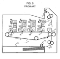
- image forming stations 10Y, 10M, 10C, and 10Bk corresponding to a plurality of colors are respectively constituted by developing means, electrophotographic photosensitive drums 1Y, 1M, 1C, and 1Bk serving as first image bearing members, and process means that act on the drums, as shown in FIG. 9 .
- the image forming stations 10Y, 10M, 10C, and 10Bk are arranged in a line so as to oppose an intermediate transfer medium 7 serving as a second image bearing member.
- Toner images of different colors are transferred one on another onto the intermediate transfer medium 7, and are transferred together onto a transfer material 13 by a secondary transfer means 8. This method is widely used because good output can be obtained, regardless of the type of the transfer material, and speedy formation of color images is possible.
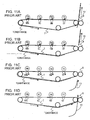
- the photosensitive drums 1Y, 1M, and 1C in the color-image forming stations 10Y, 10M, and 10C can be separated from the intermediate transfer medium 7 without rotation of the drums, as shown in FIG. 10 . In this case, the use of the photosensitive drums 1Y, 1M, and 1C is avoided during formation of a monocolor image.
- Japanese Patent Laid-Open No. 2004-4398 proposes a separation means that separates photosensitive drums Y, M, C, and Bk from an intermediate transfer belt in order to reduce the use of the photosensitive drums. Separation is performed after primary transfer of all toner images to be transferred onto the last sheet in one print job is completed, before the toner images are subjected to secondary transfer, and after secondary transfer onto the last second sheet is completed.
- switching between the modes must be performed so that image defects, such as color misregistration, are not caused by the influence of the operation of moving the intermediate transfer medium and the color-image forming stations into contact with or apart from each other.
- the intermediate transfer medium and the color-image forming stations when the full-color mode is switched to a monocolor mode, the intermediate transfer medium and the color-image forming stations must be separated while a full-color image formed on the intermediate transfer medium does not lie at a primary transfer position in the black-image forming station and at a secondary transfer position.
- the intermediate transfer medium and the color-image forming stations when a monocolor mode is switched to the full-color mode, the intermediate transfer medium and the color-image forming stations must be brought into contact with each other while a monocolor image does not lie at the primary transfer position in the black-image forming station and at the secondary transfer position.
- the non-image forming region on which a toner image is not formed (a region between image forming regions on which toner images are formed) is normally made small in order to maximize the number of prints to be continuously made.
- the period in which image formation is prohibited is shorter than the contact or separation time of the intermediate transfer medium. For this reason, it is impossible that an image does not lie at both the primary transfer position in the black-image forming station and the secondary transfer position during the contact or separation time.
- the intermediate transfer medium 7 is separated from (taken out of contact with) the color-image forming stations 10Y, 10M, and 10C after a full-color image formed on the intermediate transfer medium 7 (a monocolor image when a monocolor mode is switched to the full-color mode) passes through the secondary transfer position, and image formation in a monocolor mode is then started. Therefore, when the mode is frequently changed, the number of output images produced per unit time is reduced, and output performance is seriously reduced.
- the present invention provides a full-color image forming apparatus that prevents output performance from being reduced when the color mode is switched, without causing an image defect such as color misregistration.
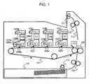
- FIG. 1 is a schematic sectional view of an image forming apparatus according to a first embodiment of the present invention.
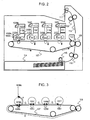
- FIG. 2 is a schematic sectional view of the image forming apparatus according to the first embodiment.
- FIG. 3 is an explanatory view showing dimensions in the image forming apparatus.
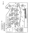
- FIG. 4 is a control block diagram of the image forming apparatus.
- FIG. 5 is a control flowchart of the image forming apparatus.
- FIGS. 6A to 6D are operational diagrams of the image forming apparatus.
- FIG. 7 is an operational diagram of the image forming apparatus.
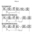
- FIG. 8 is an operational diagram of an image forming apparatus according to a second embodiment of the present invention.
- FIG. 9 is a schematic sectional view of a known image forming apparatus.
- FIG. 10 is a schematic sectional view of the known image forming apparatus.
- FIGS. 11A to 11D are operational diagrams of the known image forming apparatus.
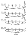
- FIGS. 12A to 12D are operational diagrams of the known image forming apparatus.
- FIG. 1 is a cross-sectional view schematically showing the configuration of an image forming apparatus according to a first embodiment of the present invention.
- the image forming apparatus of the first embodiment includes image forming stations corresponding to a plurality of colors.
- Each of the image forming stations includes a first image bearing member (hereinafter referred to as a "photosensitive drum") on which an electrostatic latent image is formed, and a developing device for developing the electrostatic latent image.
- a first image bearing member hereinafter referred to as a "photosensitive drum”
- developing device for developing the electrostatic latent image.
- the image forming apparatus also includes an intermediate transfer medium serving as a second image bearing member on which color developed images on the photosensitive drums are transferred one on the other to form a full-color developed image, and a secondary transfer device serving as a secondary transfer means for transferring the full-color developed image on the intermediate transfer medium onto a transfer material serving as a recording medium.
- an intermediate transfer medium serving as a second image bearing member on which color developed images on the photosensitive drums are transferred one on the other to form a full-color developed image
- a secondary transfer device serving as a secondary transfer means for transferring the full-color developed image on the intermediate transfer medium onto a transfer material serving as a recording medium.
- Drum-shaped electrophotographic photosensitive members that is, photosensitive drums 101Y, 101M, 101C, and 101Bk are supported rotatably.
- charging rollers 102Y, 102M, 102C, and 102Bk serving as charging means uniformly charge the surfaces of the photosensitive drums 101Y, 101M, 101C, and 101Bk, respectively.
- the surfaces of the photosensitive drums 101Y, 101M, 101C, and 101Bk are exposed to laser beams emitted in accordance with color image information by laser emitting means 103Y, 103M, 103C, and 103Bk serving as exposure means, thereby forming electrostatic latent images on the photosensitive drums 101Y, 101M, 101C, and 101Bk.
- the photosensitive drums 101Y, 101M, 101C, and 101Bk are negatively charged. Electrostatic latent images corresponding to image information are formed on portions of the photosensitive drums 101Y, 101M, 101C, and 101Bk on which negative charges is decreased by exposure to laser light emitted from the laser emitting means 103Y, 103M, 103C, and 103Bk.
- electrostatic latent images on the photosensitive drums are respectively made visible as toner images by being developed with toner serving as a kind of developer supplied from developing devices 104Y, 104M, 104C, and 104Bk.
- the toner images are sequentially transferred one on another onto an intermediate transfer medium 107 at primary transfer positions, where the photosensitive drums 101Y, 101M, 101C, and 101Bk are in contact with the intermediate transfer medium 107, by primary transfer means 105Y, 105M, 105C, and 105Bk disposed correspondingly to the photosensitive drums.
- toner remaining on the surfaces of the photosensitive drums 101Y, 101M, 101C, and 101Bk is removed by cleaning devices 106Y, 106M, 106C, and 106Bk each having a blade-shaped cleaning means.
- cleaning devices 106Y, 106M, 106C, and 106Bk each having a blade-shaped cleaning means.
- the first embodiment adopts a reversal development method. Therefore, toner having the same polarity (negative) as that of the charge adheres onto the portions of the photosensitive drums 101Y, 101M, 101C, and 101Bk (image portions) on which the negative charge is decreased.
- the photosensitive drum 101, the charging roller 102, the developing device 104, and the cleaning device 106 are combined into a process cartridge 110 (Y, M, C, and Bk) that constitutes an image forming station (Y, M, C, and Bk).
- a process cartridge 110 Y, M, C, and Bk
- Each image forming station is independently detachable from the image forming apparatus.
- Toner is supplied from toner supply units 111Y, 111M, 111C, and 111Bk serving as developer storing means to the developing devices 104Y, 104M, 104C, and 104Bk.
- One transfer material 113 is supplied from a transfer-material cassette 114 by a supply roller 115, is brought into synchronization with the toner image on the intermediate transfer medium 107 by a registration roller 116, and is conveyed to a secondary transfer position where the intermediate transfer medium 107 is in contact with a transfer roller 108 serving as a secondary transfer means.
- the toner image on the intermediate transfer medium 107 and the transfer material 113 reach the secondary transfer position, the toner image is transferred onto the transfer material 113 by a transfer electric field produced in a transfer region by the transfer roller 108. Subsequently, the unfixed toner image on the transfer material 113 is heated by a fixing means (heat roller) and is pressed by a pressing means in a fixing device 109, and is thereby fixed as a permanent image on the transfer material 113.
- a fixing means heat roller
- switching can be made between a contact state in which the photosensitive drums 101Y, 101M, and 101C of the process cartridges 110Y, 110M, and 110C in the color-image forming stations Y, M, and C are in contact with the intermediate transfer medium 107, and a separated state in which the drums are separated from the intermediate transfer medium 107.
- the photosensitive drums 101Y, 101M, and 101C of the process cartridges 110Y, 110M, and 110C in the unnecessary color-image forming stations Y, M, and C are separated from the intermediate transfer medium 107, as shown in FIG. 2 .
- a monocolor-image forming operation is performed without driving the process cartridges 110Y, 110M, and 110C.
- the photosensitive drums 101Y, 101M, and 101C of the process cartridges 110Y, 110M, and 110C in the necessary color image forming stations Y, M, and C are placed in contact with the intermediate transfer medium 107.
- a full-color image forming operation is performed while driving the process cartridges 110Y, 110M, and 110C similarly to the process cartridge 110Bk.
- the image forming apparatus operates in a "full-color mode” in which image formation is performed while the color-image forming stations are in contact with the intermediate transfer medium, and in a “monocolor mode” in which image formation is performed while the color-image forming stations are separated from the intermediate transfer medium. These modes can be selectively carried out for each page.
- the following parameters are set (see FIG. 3 ).
- the distance A from an exposure position (where an electrostatic latent image is formed) to the primary transfer position on the photosensitive drum 101 is 47 mm
- the distance B from the primary transfer position in the most downstream image forming station Bk to the secondary transfer position is 510 mm
- the length C of an image forming region (length of an A3-size sheet) is 420 mm
- the length D of a normal non-image forming region in continuous image forming operation is 50 mm
- the time T needed to move the intermediate transfer medium and the color-image forming stations into contact with or apart from each other is 0.5 sec
- the process speed (moving speed of the surface of the intermediate transfer medium) V is 150 mm/sec
- the pitch G between the image forming stations is 80 mm.
- the distance V ⁇ T for which the surface of the intermediate transfer medium moves during the operation of moving the photosensitive drums and the intermediate transfer medium into contact with or apart from each other is 75 mm.
- FIG. 4 is a control block diagram of the image forming apparatus of the first embodiment
- FIG. 5 is a flowchart showing the control executed when switching the color mode
- FIGS. 6 and 7 are operational diagrams.
- Step S1 When the image forming apparatus receives a print request from a user (host computer 120), it starts a print job (Step S1). While an image processing circuit 122 processes image data from the host computer 120 into printable image information corresponding to each color, an image-color determining means 123 determines whether the first image is full color (Step S2). When the first image is full color, the full-color mode is set (Step S3). When the first image is monocolor, it is determined whether the first subsequent image is full color or monocolor (Step S4). When the first subsequent image is full color, the full-color mode is set, similarly to the above (Step S3). When the first subsequent image is monocolor, a monocolor mode is set (Step S5). When the first color mode is set, an image forming sequence is selected correspondingly to the mode (Step S6).
- Step S7 formation of the present image is first started. Then, it is determined whether each of first to third images subsequent to the present image, which is being presently printed, is full color or monocolor, and sequences are selected corresponding to the type of the image (Steps S8, S9, S10, and S15).
- Step S19 When all the subsequent images are full color, or when only one of the images is monocolor, the full-color continuous print state is maintained (Step S19).
- the non-image forming region is enlarged immediately after the first full-color image is formed (Step S16).
- the non-image formation region passes through the primary transfer position in the most downstream image forming station (black-image forming station) 110Bk, the color-image forming stations Y, M, and C are separated from the intermediate transfer medium 107 by an intermediate transfer medium movement control means 125 serving as a color-mode switching means, and the color mode is switched to a monocolor mode (Step S17).
- the length of the non-image forming region In order to prevent the transfer at the primary transfer position and formation of the next electrostatic latent image from being influenced by the separating motion, the length of the non-image forming region needs to be larger than or equal to the distance V ⁇ T+A (122 mm) obtained by adding the distance V ⁇ T (75 mm), within which the separating motion may have an influence, and the distance A (47 mm) for which the next image moves from the laser emitting means 103Bk on the photoconductive drum 101Bk to the primary transfer position.
- the length of the non-image forming region is increased from a normal length of 50 mm to 132 mm that is the sum of 122 mm and a margin of 10 mm.
- the image forming apparatus When the first subsequent image is full color and the second and third subsequent images are monocolor, the image forming apparatus is put into a color-mode switching sequence.
- the color-mode switching sequence will be described below with reference to FIGS. 6A to 6D .
- FIG. 6A shows a normal continuous image forming state in the full-color mode.
- the length is set at 85 mm including a margin of 10 mm.
- the length of the non-image forming region needs to be larger than or equal to the distance V ⁇ T+A (122 mm) obtained by adding the distance V ⁇ T (75 mm), within which the separating motion may have an influence, and the distance A (47 mm) for which the next image moves from the laser portion 103Bk on the photosensitive drum 101Bk to the primary transfer position.
- the non-image forming region E must be placed at the secondary transfer position, and the non-image forming region F must be placed at the primary transfer position in the most downstream image forming station (black-image forming station) 110Bk. For that purpose, it is necessary to satisfy the condition that C+E+F ⁇ A+B+V ⁇ T. After the non-image forming region E is obtained, the length of the non-image forming region F is set to be larger than or equal to A+B+V ⁇ T-C-E.
- A+B+V ⁇ T-C-E is set at 127 mm or more.
- V ⁇ T+A 122 mm
- the value of 127 mm or more satisfies both the relational expressions. Therefore, the length of the non-image forming region F is set at 137 mm including a margin of 10 mm.
- the intermediate transfer medium movement control means 125 separates the intermediate transfer medium 107 from the color-image forming stations Y, M, and C, and switches the color mode to a monocolor mode (Step S14, FIG. 6C ).
- Step S18 when there is no request to print the next image, the print job is completed (Step S20).
- Step S19 When a request is received, the printing operation is continued in the set color mode (Step S19).
- Step S6 A description will now be given of a case in which an image forming sequence for a monocolor mode is selected in Step S6.
- Step S21 the operation of printing a present image in a monocolor mode is started. Then, it is determined whether each of second and third images subsequent to the present image is full color or monocolor, and a subsequent sequence is selected on the basis of the determination (Steps S22 and S23).
- Step S19 When all the images are monocolor, a continuous printing state in the monocolor mode is maintained (Step S19).
- the non-image forming region is enlarged to a region F immediately after the first monocolor image is formed (Step S28).
- the intermediate transfer medium movement control means 125 puts the intermediate transfer medium 107 into contact with the color-image forming stations Y, M, and C, and switches the color mode to the full-color mode (Step S29).
- the length of the non-image forming region F needs to be larger than or equal to the distance V ⁇ T+A (122 mm) obtained by adding the distance V ⁇ T (75 mm), within which the contact motion may have an influence, and the distance A (47 mm) for which the next image moves from the laser portion 103Bk on the photosensitive drum 101Bk to the primary transfer position.
- the length is increased from the normal length of 50 mm to 132 mm including a margin of 10 mm.
- the image forming apparatus is put into a color-mode switching sequence.
- the first subsequent image is printed in the monocolor mode (Step S25), and the non-image forming region just subsequent to the image is enlarged to F (138 m) (Step S26).
- the length of the non-image forming region F needs to be larger than or equal to the distance V ⁇ T+A (122 mm) obtained by adding the distance V ⁇ T (75 mm), within which the contact motion may have an influence, and the distance A (47 mm) for which the next image moves from the laser portion 103Bk on the photosensitive drum 101Bk to the primary transfer position.
- the non-image forming region E should be placed at the secondary transfer position, and the non-image forming region F should be placed at the primary transfer position in the most downstream image forming station (black-image forming station) 110Bk. For that purpose, it is necessary to satisfy the condition that C+E+F ⁇ A+B+V ⁇ T. After the non-image forming region E is obtained, the length of the non-image forming region F is set to be larger than or equal to A+B+V ⁇ T-C-E.
- A+B+V ⁇ T-C-E is set to be 127 mm or more.
- V ⁇ T+A 122 mm
- the value of 127 mm or more satisfies both the relational expressions. Therefore, the length of the non-image forming region F is set at 137 mm including a margin of 10 mm.
- the intermediate transfer medium movement control means 125 brings the intermediate transfer medium 107 into contact with the color image forming stations Y, M, and C, and switches the color mode to the full-color mode (Step S27).
- Step S18 when there is no request to print the next image, the print job is completed (Step S20).
- Step S19 When a request is received, the printing operation is continued in the set color mode (Step S19).
- the color-mode switching operation is controlled in the above-described manner.
- the length of one non-image forming region is much larger than the length of a normal non-image forming region D.
- the length is determined in consideration of the distance for which the image completely passes through the secondary transfer position, and the influence of movement of the intermediate transfer medium. Therefore, B+V ⁇ T+A is added when the full-color mode is switched to the monocolor mode, and the distance G ⁇ 3 for which the color-image forming stations move is further added.
- the length needs to be at least B+V ⁇ T+A+G ⁇ 3. If this is applied to the image forming apparatus of the first embodiment, the length is 632 mm (increased by 582 mm/3.88 sec compared with continuous printing) when the full-color mode is switched to the monocolor mode, and 872 mm (increased by 822 mm/5.48 sec compared with continuous printing) when the monocolor-mode is switched to the full-color mode.
- the lengths of two non-image forming regions are increased from D to E and from D to F in both switching sequences (full-color to monocolor and monocolor to full-color).
- drum rotations of the image forming stations can be reduced by shortening the switching time, the use of expendables can be reduced.
- the length of the non-image forming region is adjusted by a CPU 121 serving as a non-image-forming-region length adjusting means.
- the structure dimensions and image dimensions described in the above first embodiment allow one image to be provided within the distance B from the primary transfer position in the most downstream image forming station (Bk) to the secondary transfer position.
- the advantages of the first embodiment can also be provided by defining the number N of images that can be provided within the distance B.
- the distance from the exposure position to the primary transfer position on each photosensitive drum 101 is designated as A
- the distance from the primary transfer position in the most downstream image forming station to the secondary transfer position is designated as B
- the length of the image forming region is designated as C
- the length of the normal non-image forming region during continuous image formation is designated as D
- the time required to move the intermediate transfer medium and the color-image forming stations into contact with or apart from each other is designated as T
- the process speed (moving speed of the surface of the intermediate transfer medium) is designated as V
- the distance for which the surface of the intermediate transfer medium moves during the contact or separating operation is designated as V ⁇ T.
- the enlarged non-image forming region lies between the secondary transfer position and the primary transfer position in the most downstream image forming station.
- the intermediate transfer medium is separated from the color-image forming stations.
- the non-image forming region subsequent to the present image and the non-image forming region subsequent to the N-th subsequent image are similarly enlarged, as shown in FIG. 8 . Consequently, the enlarged non-image forming region lies between the secondary transfer position and the primary transfer position in the most downstream image forming station.
- the intermediate transfer medium is brought into contact with the color-image forming stations.
Landscapes
- Physics & Mathematics (AREA)
- General Physics & Mathematics (AREA)
- Engineering & Computer Science (AREA)
- Microelectronics & Electronic Packaging (AREA)
- Color Electrophotography (AREA)
- Electrostatic Charge, Transfer And Separation In Electrography (AREA)
Applications Claiming Priority (1)
| Application Number | Priority Date | Filing Date | Title |
|---|---|---|---|
| JP2004358565A JP4649189B2 (ja) | 2004-12-10 | 2004-12-10 | 画像形成装置 |
Publications (3)
| Publication Number | Publication Date |
|---|---|
| EP1674942A2 EP1674942A2 (en) | 2006-06-28 |
| EP1674942A3 EP1674942A3 (en) | 2008-01-16 |
| EP1674942B1 true EP1674942B1 (en) | 2011-02-23 |
Family
ID=36010887
Family Applications (1)
| Application Number | Title | Priority Date | Filing Date |
|---|---|---|---|
| EP05257585A Expired - Lifetime EP1674942B1 (en) | 2004-12-10 | 2005-12-09 | Image formation apparatus with switching between color printing mode and monochrome printing mode |
Country Status (6)
| Country | Link |
|---|---|
| US (1) | US7349658B2 (enExample) |
| EP (1) | EP1674942B1 (enExample) |
| JP (1) | JP4649189B2 (enExample) |
| KR (1) | KR100776838B1 (enExample) |
| CN (1) | CN100435039C (enExample) |
| DE (1) | DE602005026493D1 (enExample) |
Families Citing this family (11)
| Publication number | Priority date | Publication date | Assignee | Title |
|---|---|---|---|---|
| JP4652798B2 (ja) * | 2004-12-17 | 2011-03-16 | キヤノン株式会社 | カラー画像形成装置 |
| JP2007199131A (ja) * | 2006-01-24 | 2007-08-09 | Fuji Xerox Co Ltd | 画像形成装置 |
| JP4943194B2 (ja) * | 2007-03-15 | 2012-05-30 | 株式会社東芝 | 画像形成装置及び画像形成方法 |
| US7801455B2 (en) * | 2007-12-21 | 2010-09-21 | Xerox Corporation | Architecture for a multi toner printing system |
| US8005391B2 (en) * | 2008-03-17 | 2011-08-23 | Lexmark International, Inc. | Methods for determining when to transition between color printing and black-only printing in an image forming device |
| JP2012063631A (ja) * | 2010-09-16 | 2012-03-29 | Ricoh Co Ltd | 画像形成装置 |
| JP5640860B2 (ja) * | 2011-03-29 | 2014-12-17 | コニカミノルタ株式会社 | 画像形成装置 |
| JP6494372B2 (ja) * | 2015-03-31 | 2019-04-03 | キヤノン株式会社 | 画像形成装置 |
| JP6808371B2 (ja) * | 2016-06-21 | 2021-01-06 | キヤノン株式会社 | 画像形成装置 |
| JP2019117302A (ja) * | 2017-12-27 | 2019-07-18 | 株式会社沖データ | 画像形成装置 |
| JP7700595B2 (ja) * | 2021-09-06 | 2025-07-01 | 株式会社リコー | 画像形成装置 |
Family Cites Families (12)
| Publication number | Priority date | Publication date | Assignee | Title |
|---|---|---|---|---|
| JP3750301B2 (ja) * | 1997-08-29 | 2006-03-01 | コニカミノルタビジネステクノロジーズ株式会社 | 画像形成装置 |
| JP4183219B2 (ja) * | 1999-12-21 | 2008-11-19 | フジノン株式会社 | フーリエ変換を用いた縞解析方法 |
| JP2001331013A (ja) * | 2000-05-18 | 2001-11-30 | Canon Inc | 画像形成装置 |
| JP3791366B2 (ja) * | 2001-08-21 | 2006-06-28 | コニカミノルタビジネステクノロジーズ株式会社 | 画像形成装置 |
| JP2003149901A (ja) * | 2001-11-16 | 2003-05-21 | Sharp Corp | カラー画像形成装置およびその制御方法 |
| JP3977129B2 (ja) * | 2002-04-16 | 2007-09-19 | キヤノン株式会社 | 画像形成装置 |
| JP2003337454A (ja) * | 2002-05-21 | 2003-11-28 | Fuji Xerox Co Ltd | 画像形成装置 |
| WO2003102697A2 (en) | 2002-06-03 | 2003-12-11 | Matsushita Electric Industrial Co., Ltd. | Color image forming apparatus |
| JP2004004398A (ja) * | 2002-06-03 | 2004-01-08 | Matsushita Electric Ind Co Ltd | カラー画像形成装置 |
| JP2004029057A (ja) * | 2002-06-21 | 2004-01-29 | Canon Inc | 画像形成装置 |
| US7085524B2 (en) * | 2002-11-29 | 2006-08-01 | Canon Kabushiki Kaisha | Image forming apparatus |
| EP1431837B1 (en) * | 2002-12-20 | 2014-12-03 | Ricoh Company, Ltd. | A colour image forming apparatus with installable process cartridges |
-
2004
- 2004-12-10 JP JP2004358565A patent/JP4649189B2/ja not_active Expired - Fee Related
-
2005
- 2005-12-06 US US11/295,077 patent/US7349658B2/en active Active
- 2005-12-09 KR KR1020050120411A patent/KR100776838B1/ko not_active Expired - Fee Related
- 2005-12-09 DE DE602005026493T patent/DE602005026493D1/de not_active Expired - Lifetime
- 2005-12-09 CN CNB2005101304325A patent/CN100435039C/zh not_active Expired - Fee Related
- 2005-12-09 EP EP05257585A patent/EP1674942B1/en not_active Expired - Lifetime
Also Published As
| Publication number | Publication date |
|---|---|
| EP1674942A2 (en) | 2006-06-28 |
| KR100776838B1 (ko) | 2007-11-16 |
| US7349658B2 (en) | 2008-03-25 |
| JP2006163287A (ja) | 2006-06-22 |
| CN100435039C (zh) | 2008-11-19 |
| KR20060065547A (ko) | 2006-06-14 |
| CN1786841A (zh) | 2006-06-14 |
| DE602005026493D1 (de) | 2011-04-07 |
| US20060127139A1 (en) | 2006-06-15 |
| EP1674942A3 (en) | 2008-01-16 |
| JP4649189B2 (ja) | 2011-03-09 |
Similar Documents
| Publication | Publication Date | Title |
|---|---|---|
| EP1096332B1 (en) | Image forming apparatus | |
| EP1674942B1 (en) | Image formation apparatus with switching between color printing mode and monochrome printing mode | |
| US20080317492A1 (en) | Color image forming apparatus, and program and method of controlling a color image forming apparatus | |
| JP2010250269A (ja) | 画像形成装置 | |
| US7317890B2 (en) | Apparatus for and method of printing a mono-color image using a single-pass color printer | |
| US7667861B2 (en) | Image forming apparatus | |
| US9563170B2 (en) | Image forming apparatus configured to use a common driving source for image bearing members | |
| CN100359413C (zh) | 图像形成装置 | |
| JP2001092202A (ja) | 画像形成装置 | |
| JP2006130779A (ja) | 画像形成装置 | |
| JP4813805B2 (ja) | 画像形成装置 | |
| JP4164503B2 (ja) | 画像形成装置。 | |
| US9057996B2 (en) | Image forming device and method for controlling a power supply for transfer | |
| JPH1152756A (ja) | 画像形成装置及びこの画像形成装置の制御プログラムを記録した記録媒体 | |
| JP2025162514A (ja) | 画像形成装置 | |
| JP5241651B2 (ja) | 画像形成装置 | |
| JP2002251077A (ja) | 画像形成装置 | |
| JPH07134531A (ja) | 複写機の動作制御方法 | |
| JP2021056427A (ja) | 画像形成装置 | |
| JPH09297449A (ja) | カラー画像形成装置 | |
| JP2004237611A (ja) | 印刷装置 | |
| JPH09319181A (ja) | 画像形成装置 | |
| JPH0318868A (ja) | カラー画像形成装置 | |
| JP2005115003A (ja) | 画像形成装置 | |
| JPH05188721A (ja) | 画像形成装置 |
Legal Events
| Date | Code | Title | Description |
|---|---|---|---|
| PUAI | Public reference made under article 153(3) epc to a published international application that has entered the european phase |
Free format text: ORIGINAL CODE: 0009012 |
|
| AK | Designated contracting states |
Kind code of ref document: A2 Designated state(s): AT BE BG CH CY CZ DE DK EE ES FI FR GB GR HU IE IS IT LI LT LU LV MC NL PL PT RO SE SI SK TR |
|
| AX | Request for extension of the european patent |
Extension state: AL BA HR MK YU |
|
| PUAL | Search report despatched |
Free format text: ORIGINAL CODE: 0009013 |
|
| AK | Designated contracting states |
Kind code of ref document: A3 Designated state(s): AT BE BG CH CY CZ DE DK EE ES FI FR GB GR HU IE IS IT LI LT LU LV MC NL PL PT RO SE SI SK TR |
|
| AX | Request for extension of the european patent |
Extension state: AL BA HR MK YU |
|
| 17P | Request for examination filed |
Effective date: 20080716 |
|
| AKX | Designation fees paid |
Designated state(s): DE FR GB |
|
| GRAP | Despatch of communication of intention to grant a patent |
Free format text: ORIGINAL CODE: EPIDOSNIGR1 |
|
| GRAC | Information related to communication of intention to grant a patent modified |
Free format text: ORIGINAL CODE: EPIDOSCIGR1 |
|
| GRAS | Grant fee paid |
Free format text: ORIGINAL CODE: EPIDOSNIGR3 |
|
| GRAA | (expected) grant |
Free format text: ORIGINAL CODE: 0009210 |
|
| AK | Designated contracting states |
Kind code of ref document: B1 Designated state(s): DE FR GB |
|
| REG | Reference to a national code |
Ref country code: GB Ref legal event code: FG4D |
|
| REF | Corresponds to: |
Ref document number: 602005026493 Country of ref document: DE Date of ref document: 20110407 Kind code of ref document: P |
|
| REG | Reference to a national code |
Ref country code: DE Ref legal event code: R096 Ref document number: 602005026493 Country of ref document: DE Effective date: 20110407 |
|
| PLBE | No opposition filed within time limit |
Free format text: ORIGINAL CODE: 0009261 |
|
| STAA | Information on the status of an ep patent application or granted ep patent |
Free format text: STATUS: NO OPPOSITION FILED WITHIN TIME LIMIT |
|
| 26N | No opposition filed |
Effective date: 20111124 |
|
| REG | Reference to a national code |
Ref country code: DE Ref legal event code: R097 Ref document number: 602005026493 Country of ref document: DE Effective date: 20111124 |
|
| PGFP | Annual fee paid to national office [announced via postgrant information from national office to epo] |
Ref country code: FR Payment date: 20141223 Year of fee payment: 10 |
|
| REG | Reference to a national code |
Ref country code: FR Ref legal event code: ST Effective date: 20160831 |
|
| PG25 | Lapsed in a contracting state [announced via postgrant information from national office to epo] |
Ref country code: FR Free format text: LAPSE BECAUSE OF NON-PAYMENT OF DUE FEES Effective date: 20151231 |
|
| PGFP | Annual fee paid to national office [announced via postgrant information from national office to epo] |
Ref country code: GB Payment date: 20201021 Year of fee payment: 16 Ref country code: DE Payment date: 20201020 Year of fee payment: 16 |
|
| REG | Reference to a national code |
Ref country code: DE Ref legal event code: R119 Ref document number: 602005026493 Country of ref document: DE |
|
| GBPC | Gb: european patent ceased through non-payment of renewal fee |
Effective date: 20211209 |
|
| PG25 | Lapsed in a contracting state [announced via postgrant information from national office to epo] |
Ref country code: GB Free format text: LAPSE BECAUSE OF NON-PAYMENT OF DUE FEES Effective date: 20211209 Ref country code: DE Free format text: LAPSE BECAUSE OF NON-PAYMENT OF DUE FEES Effective date: 20220701 |