EP1670875B1 - Hocheffizientes beleuchtungssystem auf led-basis mit verbesserter farbwiedergabe - Google Patents
Hocheffizientes beleuchtungssystem auf led-basis mit verbesserter farbwiedergabe Download PDFInfo
- Publication number
- EP1670875B1 EP1670875B1 EP04786851.8A EP04786851A EP1670875B1 EP 1670875 B1 EP1670875 B1 EP 1670875B1 EP 04786851 A EP04786851 A EP 04786851A EP 1670875 B1 EP1670875 B1 EP 1670875B1
- Authority
- EP
- European Patent Office
- Prior art keywords
- led
- lighting system
- green
- leds
- phosphor
- Prior art date
- Legal status (The legal status is an assumption and is not a legal conclusion. Google has not performed a legal analysis and makes no representation as to the accuracy of the status listed.)
- Expired - Lifetime
Links
Images

Classifications
-
- C—CHEMISTRY; METALLURGY
- C09—DYES; PAINTS; POLISHES; NATURAL RESINS; ADHESIVES; COMPOSITIONS NOT OTHERWISE PROVIDED FOR; APPLICATIONS OF MATERIALS NOT OTHERWISE PROVIDED FOR
- C09K—MATERIALS FOR MISCELLANEOUS APPLICATIONS, NOT PROVIDED FOR ELSEWHERE
- C09K11/00—Luminescent materials, e.g. electroluminescent or chemiluminescent
- C09K11/08—Luminescent materials, e.g. electroluminescent or chemiluminescent containing inorganic luminescent materials
- C09K11/77—Luminescent materials, e.g. electroluminescent or chemiluminescent containing inorganic luminescent materials containing rare earth metals
- C09K11/7728—Luminescent materials, e.g. electroluminescent or chemiluminescent containing inorganic luminescent materials containing rare earth metals containing europium
-
- H—ELECTRICITY
- H05—ELECTRIC TECHNIQUES NOT OTHERWISE PROVIDED FOR
- H05B—ELECTRIC HEATING; ELECTRIC LIGHT SOURCES NOT OTHERWISE PROVIDED FOR; CIRCUIT ARRANGEMENTS FOR ELECTRIC LIGHT SOURCES, IN GENERAL
- H05B45/00—Circuit arrangements for operating light-emitting diodes [LED]
- H05B45/20—Controlling the colour of the light
-
- F—MECHANICAL ENGINEERING; LIGHTING; HEATING; WEAPONS; BLASTING
- F21—LIGHTING
- F21V—FUNCTIONAL FEATURES OR DETAILS OF LIGHTING DEVICES OR SYSTEMS THEREOF; STRUCTURAL COMBINATIONS OF LIGHTING DEVICES WITH OTHER ARTICLES, NOT OTHERWISE PROVIDED FOR
- F21V23/00—Arrangement of electric circuit elements in or on lighting devices
- F21V23/003—Arrangement of electric circuit elements in or on lighting devices the elements being electronics drivers or controllers for operating the light source, e.g. for a LED array
- F21V23/004—Arrangement of electric circuit elements in or on lighting devices the elements being electronics drivers or controllers for operating the light source, e.g. for a LED array arranged on a substrate, e.g. a printed circuit board
- F21V23/005—Arrangement of electric circuit elements in or on lighting devices the elements being electronics drivers or controllers for operating the light source, e.g. for a LED array arranged on a substrate, e.g. a printed circuit board the substrate is supporting also the light source
-
- F—MECHANICAL ENGINEERING; LIGHTING; HEATING; WEAPONS; BLASTING
- F21—LIGHTING
- F21V—FUNCTIONAL FEATURES OR DETAILS OF LIGHTING DEVICES OR SYSTEMS THEREOF; STRUCTURAL COMBINATIONS OF LIGHTING DEVICES WITH OTHER ARTICLES, NOT OTHERWISE PROVIDED FOR
- F21V31/00—Gas-tight or water-tight arrangements
- F21V31/04—Provision of filling media
-
- F—MECHANICAL ENGINEERING; LIGHTING; HEATING; WEAPONS; BLASTING
- F21—LIGHTING
- F21Y—INDEXING SCHEME ASSOCIATED WITH SUBCLASSES F21K, F21L, F21S and F21V, RELATING TO THE FORM OR THE KIND OF THE LIGHT SOURCES OR OF THE COLOUR OF THE LIGHT EMITTED
- F21Y2113/00—Combination of light sources
- F21Y2113/10—Combination of light sources of different colours
- F21Y2113/13—Combination of light sources of different colours comprising an assembly of point-like light sources
- F21Y2113/17—Combination of light sources of different colours comprising an assembly of point-like light sources forming a single encapsulated light source
-
- F—MECHANICAL ENGINEERING; LIGHTING; HEATING; WEAPONS; BLASTING
- F21—LIGHTING
- F21Y—INDEXING SCHEME ASSOCIATED WITH SUBCLASSES F21K, F21L, F21S and F21V, RELATING TO THE FORM OR THE KIND OF THE LIGHT SOURCES OR OF THE COLOUR OF THE LIGHT EMITTED
- F21Y2115/00—Light-generating elements of semiconductor light sources
- F21Y2115/10—Light-emitting diodes [LED]
-
- H—ELECTRICITY
- H10—SEMICONDUCTOR DEVICES; ELECTRIC SOLID-STATE DEVICES NOT OTHERWISE PROVIDED FOR
- H10H—INORGANIC LIGHT-EMITTING SEMICONDUCTOR DEVICES HAVING POTENTIAL BARRIERS
- H10H20/00—Individual inorganic light-emitting semiconductor devices having potential barriers, e.g. light-emitting diodes [LED]
- H10H20/80—Constructional details
- H10H20/85—Packages
- H10H20/851—Wavelength conversion means
-
- H—ELECTRICITY
- H10—SEMICONDUCTOR DEVICES; ELECTRIC SOLID-STATE DEVICES NOT OTHERWISE PROVIDED FOR
- H10W—GENERIC PACKAGES, INTERCONNECTIONS, CONNECTORS OR OTHER CONSTRUCTIONAL DETAILS OF DEVICES COVERED BY CLASS H10
- H10W72/00—Interconnections or connectors in packages
- H10W72/50—Bond wires
- H10W72/531—Shapes of wire connectors
- H10W72/536—Shapes of wire connectors the connected ends being ball-shaped
-
- H—ELECTRICITY
- H10—SEMICONDUCTOR DEVICES; ELECTRIC SOLID-STATE DEVICES NOT OTHERWISE PROVIDED FOR
- H10W—GENERIC PACKAGES, INTERCONNECTIONS, CONNECTORS OR OTHER CONSTRUCTIONAL DETAILS OF DEVICES COVERED BY CLASS H10
- H10W72/00—Interconnections or connectors in packages
- H10W72/50—Bond wires
- H10W72/531—Shapes of wire connectors
- H10W72/5363—Shapes of wire connectors the connected ends being wedge-shaped
-
- H—ELECTRICITY
- H10—SEMICONDUCTOR DEVICES; ELECTRIC SOLID-STATE DEVICES NOT OTHERWISE PROVIDED FOR
- H10W—GENERIC PACKAGES, INTERCONNECTIONS, CONNECTORS OR OTHER CONSTRUCTIONAL DETAILS OF DEVICES COVERED BY CLASS H10
- H10W72/00—Interconnections or connectors in packages
- H10W72/851—Dispositions of multiple connectors or interconnections
- H10W72/874—On different surfaces
- H10W72/884—Die-attach connectors and bond wires
-
- H—ELECTRICITY
- H10—SEMICONDUCTOR DEVICES; ELECTRIC SOLID-STATE DEVICES NOT OTHERWISE PROVIDED FOR
- H10W—GENERIC PACKAGES, INTERCONNECTIONS, CONNECTORS OR OTHER CONSTRUCTIONAL DETAILS OF DEVICES COVERED BY CLASS H10
- H10W90/00—Package configurations
-
- H—ELECTRICITY
- H10—SEMICONDUCTOR DEVICES; ELECTRIC SOLID-STATE DEVICES NOT OTHERWISE PROVIDED FOR
- H10W—GENERIC PACKAGES, INTERCONNECTIONS, CONNECTORS OR OTHER CONSTRUCTIONAL DETAILS OF DEVICES COVERED BY CLASS H10
- H10W90/00—Package configurations
- H10W90/701—Package configurations characterised by the relative positions of pads or connectors relative to package parts
- H10W90/731—Package configurations characterised by the relative positions of pads or connectors relative to package parts of die-attach connectors
- H10W90/736—Package configurations characterised by the relative positions of pads or connectors relative to package parts of die-attach connectors between a chip and a stacked lead frame, conducting package substrate or heat sink
-
- H—ELECTRICITY
- H10—SEMICONDUCTOR DEVICES; ELECTRIC SOLID-STATE DEVICES NOT OTHERWISE PROVIDED FOR
- H10W—GENERIC PACKAGES, INTERCONNECTIONS, CONNECTORS OR OTHER CONSTRUCTIONAL DETAILS OF DEVICES COVERED BY CLASS H10
- H10W90/00—Package configurations
- H10W90/701—Package configurations characterised by the relative positions of pads or connectors relative to package parts
- H10W90/751—Package configurations characterised by the relative positions of pads or connectors relative to package parts of bond wires
- H10W90/756—Package configurations characterised by the relative positions of pads or connectors relative to package parts of bond wires between a chip and a stacked lead frame, conducting package substrate or heat sink
Definitions
- the invention is based on a highly efficient LED-based illumination system with improved color rendering. These are in particular luminescence conversion LEDs, which are in particular fully tunable.
- RGB red-green-blue
- a blue LED can be used for the partial conversion of two phosphors which emit red and green.
- the search for an efficient green light for an RGB system is currently in the spotlight, such as the proposal US 6,255,670 shows.
- a UV emitting LED is used, which excites three phosphors, each having their emission in the red, green and blue, see WO 97/48138 , Examples are line emitters like YOB: Ce, Tb (green) and YOS: Eu (red).
- UV range ⁇ 370 nm a relatively short-wave emission
- sapphire substrates for the UV-LED which are very expensive.
- using a UV LED based on the cheaper SiC substrates one must be satisfied with an emission in the range 380 to 420 nm.
- the individual colors of the system RGB can basically be generated by the primary radiation of LEDs or by luminescence conversion LEDs, such as WO 01/41215 illustrated.
- DE-OS 101 37 042 presents a planar illumination system with special coupling of the blue portion to avoid the usual absorption problems with blue phosphors.
- WO 2004/030109 (Art. 54 (3)) and EP 1 413 618 (Art. 54 (3)) describe a lighting system in which an LED is preceded by at least one phosphor.
- RGB LEDs are interesting, consisting of three chips with the emission colors RGB. Since all three colors are realized by different LEDs, all three components can be controlled independently of each other. Therefore, it is possible with this type of lighting system targeted to set almost any desired color location via a corresponding control electronics.
- a disadvantage of this solution is a very low color rendering index Ra ⁇ 50, which results from the narrow banding of the three individual emissions.
- Another disadvantage is that the green LED used for technological reasons is much less efficient than the other two components, In addition, the color location depends heavily on the operating current and the temperature.
- LEDs are used where part of the primary LED emission is converted to longer wavelength light, especially green.
- this setup is not tunable because the secondary component is not independent of the primary component.
- This HT modification is characterized by the fact that it can be excited broadband excitation that it has an extremely high stability to external influences, so at 150 ° C shows no measurable degradation, that it shows an extremely good color stability under changing conditions (between 20 and 100 ° C little drift detectable). Other pluses are its low absorption in the red, which is particularly advantageous in phosphor mixtures.
- This phosphor is often called Sr-sion: Eu in the following.
- the synthesis range is 1300 to 1600 ° C.
- Another determining factor is the reactivity of the starting components. This should be as high as possible.
- the two phases differ fundamentally in their suitability as a phosphor. While the NT phase as an Eudotierter phosphor is limited to use, and more orange-red emitted, the HT phase shows excellent suitability as a phosphor that emits green. Often there is a mixture of both modifications, which shows broadband both emissions. It is therefore desirable to produce the HT phase as pure as possible, with at least 50% proportion, preferably at least 70%, particularly preferably at least 85% proportion.
- annealing process that is performed at a minimum of 1300 ° C but not more than 1600 ° C.
- Preference is given to a temperature range of about 1450 to 1580 ° C, since at lower temperature increasingly NT phase is formed and at higher temperature, the phosphor is increasingly difficult to process, and is present from about 1600 ° C as a hard sintered ceramic or melt.
- the optimum temperature range depends on the exact composition and properties of the starting materials.
- Sr-Sion phosphor is an approach of the starting materials, which is substantially stoichiometric using the basic components SiO 2 , SrCO 3 and Si 3 N 4 .
- Sr is hereby exemplified by M.
- the deviation should in particular not exceed 10%, preferably 5%, of the ideal stoichiometric approach, whereby also the possible addition of a flux, as is often the case, is included.
- Particularly preferred is a maximum deviation of 1%.
- the europium contribution of the doping which is realized, for example, as oxide Eu 2 O 3 .
- the basic component of SiO 2 clearly substoichiometric admit. This finding is also particularly surprising because other Sions recommended as phosphor such as Ba-Sion according to the teaching of EP-PA 02 021 117.8 just in the SiO 2 sub-shot to be produced.
- a corresponding approach for the Sr sion MSi 2 O 2 N 2 therefore uses 11 to 13 wt .-% SiO 2 , 27 to 29 wt .-% Si 3 N 4 , balance SrCO 3 .
- Ba and Ca fractions of M are added as carbonate accordingly.
- Europium is added according to the desired doping, for example as oxide or fluoride, as a replacement for SrCO 3 .
- the approach MSi 2 O 2 N 2 also means any deviations from the exact stoichiometry, as far as they are balanced in terms of charge retention.
- the starting components of the host lattice in particular Si 3 N 4 , have the highest possible purity. Therefore, Si 3 N 4 , which is synthesized from the liquid phase, starting, for example, from silicon tetrachloride, is particularly preferred.
- the contamination with tungsten and cobalt has proven to be critical.
- the contamination should be as low as possible, in particular, it should each be less than 100 ppm, in particular less than 50 ppm, based on these precursors.
- the highest possible reactivity is advantageous, it can be quantified by the reactive surface (BET). This should be at least 6 m 2 / g, advantageously at least 8 m 2 / g.
- the contamination of aluminum and calcium, based on this precursor Si 3 N 4 should be as possible below 100 ppm.
- This HT modification draws characterized by the fact that it can be excited broadband, namely in a wide range of 50 to 480 nm, in particular 150 to 480 nm, particularly preferably from 250 to 470 nm, that it has an extremely high stability to external influences, ie at 150 ° C shows no measurable degradation in air and that it shows extremely good color stability under changing conditions.
- Other pluses are its low absorption in the red, which is particularly advantageous in phosphor mixtures.
- This phosphor is often called Sr-sion: Eu in the following.
- a predominance of the HT modification is evident inter alia from the fact that the characteristic peak of the NT modification in the XRD spectrum at about 28.2 ° an intensity of less than 1: 1, preferably less than 1: 2, compared to the peak with highest intensity from the triad of reflections of HT modification, which are in the XRD spectrum at 25 to 27 °, has.
- the XRD spectra listed here each refer to an excitation by the known Cu-K ⁇ line.
- the half-width of the HT variant is significantly lower in the case of the optimized HT variant than in the simple foreign phase and defect-containing mixture and is in the range 70 to 80 nm, while the simple foreign phase or defect-containing mixture has a half-width of about 110 to 120 nm shows.
- the dominant wavelength is generally shorter for the HT modification, typically 10 to 20 nm shorter, than for a sample which contains much foreign phase.
- the efficiency of the high-purity HT modification is typically at least 20% higher, sometimes significantly higher, than in the case of the NT-dominated or highly foreign phase-containing mixture.
- a characteristic feature of a sufficiently small proportion of the NT modification and foreign phases is a half-width (FWHM) of the emission of less than 90 nm.
- FWHM half-width
- the predominant peak in the XRD spectrum of the HT modification is the peak at about 31.7 °.
- other prominent peaks are the three peaks of approximately equal intensity between 25 and 27 ° (25.3 and 26.0 and 26.3 °), with the minimum deflection peak being the most intense.
- another intense peak is 12.6 °.
- This phosphor is mainly green emitting with a dominant wavelength in the range 550 to 570 nm, in particular 555 to 565 nm.
- Both phases of Sr-sion: Eu can crystallize analogously to the two structurally different host lattice modifications and can be prepared in each case via the stoichiometry SrSi2O2N2: Eu. Small deviations from this stoichiometry are possible.
- the Eu-doped host lattices surprisingly both luminesce upon excitation in the blue or UV, but depending on the host lattice modification with different emission color.
- a desired property of the phosphor can be set precisely.
- An advantage of the HT phase is the uniformly good excitability over a very wide spectral range with only little varying quantum efficiency.
- the luminescence of the HT modification in a wide temperature range depends only weakly on the temperature. This is the first time a green emitting phosphor, preferably for LED applications, found that manages without special measures for stabilization. This distinguishes him especially against the hitherto regarded as the most promising candidate phosphors for this task, namely thiogallate phosphors or chlorosilicates.
- the Sion compounds with M (Sr, Ba), preferably without Ba or with Ba content up to 10%, are efficient phosphors with a wide range of emission maxima. These are usually shorter wavelength than pure Sr-Sion, preferably between 520 and 565 nm.
- the achievable color space can also be reduced by small additions expand (preferably to 30 mol%) of Ca and / or zinc; As a result, the emission maxima are shifted to the longer wavelength range, compared to pure Sr-Sion, and by partial replacement (up to 25 mol%) of Si by Ge and / or Sn.
- Another embodiment is the partial substitution of M, in particular Sr, by tri- or monovalent ions such as Y 3+, La 3+ or Li + or Na +. A proportion of these ions of not more than 20 mol% of M. is preferred.
- this phosphor has advantages in use in a lighting system, replacing as green phosphor previous inefficient solutions for the green components.
- the excitation of the phosphor is carried out either by a blue LED with high-efficiency primary radiation, or by a UV LED. Since the green emission is relatively broadband, compared to other technological solutions such as thiogallates or chlorosilicates, sets a significantly increased color rendering index.
- This luminescent material is particularly suitable for applications with full color luminescence conversion LEDs as well as luminescence conversion LEDs with arbitrary adjustable colors based on a UV blue primary emitting LED. Conversion by the phosphor of the present invention provides cyan to greenish yellow colors.
- the mixed compounds with M (Sr, Ba) are efficient phosphors with a wide range of emission maxima. These lie between 520 and 570 nm.
- the achievable color space can also be characterized by small amounts (preferably up to 30 mol%) of Ca and /. or zinc, as well as by partial replacement (up to 25 mol%) of Si by Ge and / or Sn.
- Another embodiment is the partial substitution of M, in particular Sr, by trivalent or monovalent ions such as La 3+ or Li +.
- a proportion of not more than 20 mol% of M. is preferred.
- the phosphor according to the invention can preferably be used for luminescence conversion LED for generating white light, be it with blue primary radiation, or else with UV primary radiation, wherein white light is generated by means of blue and yellow-green emitting phosphors.
- phosphors for the blue component are known per se, for example, BaMgAl 10 O 17 : Eu 2+ (known as BAM) or Ba 5 SiO 4 (Cl, Br) 6 : Eu 2+ or CaLa 2 S 4 : Ce 3+ or (Sr, Ba, Ca) 5 (PO 4 ) 3 Cl: EU 2+ (known as SCAP).
- BAM BaMgAl 10 O 17
- Ba 5 SiO 4 (Cl, Br) 6 Eu 2+
- CaLa 2 S 4 Ce 3+
- Sr, Ba, Ca) 5 (PO 4 ) 3 Cl EU 2+
- EU 2+ known as SCAP
- a red phosphor is additionally used. Preference is given to the use of an additional primary red emitting LED. In particular, it is used together with a blue-emitting base LED ((Y, La, Gd, Lu) 2 O 2 S: Eu 3+ , SrS: Eu 2+, or (Ca, Sr) 2 Si 5 N 8 : Eu 2+ , especially with high Ca content.
- a blue-emitting base LED ((Y, La, Gd, Lu) 2 O 2 S: Eu 3+ , SrS: Eu 2+, or (Ca, Sr) 2 Si 5 N 8 : Eu 2+
- values of the color rendering index Ra of 85 to 95 can be achieved without sacrificing the dimming of the illumination system.
- an RGB illumination technique using only nitride-based phosphors, using a high-efficiency blue dominant-wavelength LED of 440 to 465 nm, preferably 460 nm peak wavelength, together with luminescence conversion LEDs.
- a first luminescence conversion LED uses a blue LED, preferably at 460 nm peak wavelength, as the primary light source, converted by the above-described Sr sion as a green secondary light source.
- a second luminescence conversion LED employs a blue LED, preferably at about 460 nm peak wavelength, as the primary light source, converted by a (Ca, Sr) 2 Si 5 N 8 : Eu 2+ type nitridosilicate as a red secondary light source.
- these three components complement each other almost ideally in their spectrum, so that the high color rendering at high efficiency is possible.
- the technical realization of the lighting system according to the invention can be done in several ways.
- so-called multichip LEDs are of interest, Here are the different chips in a housing. As a rule, these are two or three chips.
- the first LED in a first embodiment, is a UV LED emitting primarily in the range 340 to 430 nm, which excites the green phosphor for secondary emission.
- the second LED is the red emitting LED.
- a third LED is used which preferably emits itself primarily blue (430 to 470 nm peak) or in which a blue phosphor is excited by a primary UV emitting LED.
- the first LED is either primarily UV-emitting in the range 340 to 420 nm, wherein it is preceded by a blue-emitting phosphor and the novel green-emitting phosphor. These two phosphors completely convert the UV radiation of the first LED.
- the first LED is a blue-emitting LED with a peak in the range 430 to 470 nm, preceded by a novel green emitting phosphor which partially converts the primary light of the LED into green secondary radiation.
- the second LED is again the red emitting LED.
- the red portion is generated by conversion of a shorter-wave radiation, such as a UV LED or blue LED.
- LEDs described here can also be understood as groups of similar LEDs.
- the individual chips are provided locally with the respective phosphor.
- the individual chips may for this purpose be located in different cavities or cavities or together in a single cavity.
- the chips are usually already provided in a pre-process with the phosphor.
- the application of the phosphor can also take place only after the installation of the chips in the housing of the lighting system.
- the phosphors described are particularly suitable for near-chip conversion techniques, as known per se in the literature, see for example DE 102 03 795 ,
- the invention further relates to a lighting system with LEDs as described above, wherein the lighting system further includes electronic components. These convey, for example, the dimmability.
- Another task of the electronics is the control of individual LEDs or groups of LEDs. These functions can be realized by previously known electronic elements.
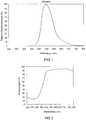
- FIG. 1 A concrete example of the highly efficient green emitting phosphor is in FIG. 1 shown. This is the emission of the phosphor SrSi 2 N 2 O 2 : (10% Eu 2+ ) in HT modification, in which the Eu content accounts for 10 mol% of the lattice sites occupied by Sr.
- the emission maximum is 545 nm, the mean dominant wavelength at 564 nm ( ⁇ dom).
- the excitation takes place at 460 nm.
- the FWHM is 84 nm.
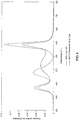
- FIG. 2 shows the diffuse reflection spectrum of this phosphor. It shows a pronounced minimum in the range below 430 nm, which thus demonstrates the good excitability in this area.
- the construction of a light source for white light is in Figure 3a, 3b shown explicitly.
- the light source is a type LED semiconductor device 6 having a first InGaN type chip 1 with a peak emission wavelength of, for example 460 nm, and a second InGaAlP chip 2 having a peak emission wavelength of, for example, 620 nm, and finally a luminescence conversion LED type semiconductor device having a third InGaN chip 3 having a primary peak emission wavelength of 460 nm, for example.
- the semiconductor device 6 is different embedded in an opaque base housing 8 similar elements.
- This solution has the great advantage of being tunable in a wide range of color temperatures by changing the relative intensities of the three LEDs by electronic control 7.
- a comparison, see Table 1, with the previously available solution with three primary emitting LEDs (RGB, where green was realized by an InGaN LED with ⁇ dom 526) shows impressively the superiority of the new solution.
- Fig. 3a shows an LED 6 in magnification.
- FIG. 4 shows the emission of such an illumination system as a spectral distribution (intensity in arbitrary units) over the wavelength (in nm).
- the dashed line shows the old solution (three primary emitting LEDs) compared to the new solution (two primary emitting LEDs and a green luminescence conversion LED) for a 4000 K color temperature.
- the particular advantage of using a long wavelength primary light source (450 to 465 nm) for the green luminescence conversion LED is that it avoids problems with aging and degradation of the package and resin or phosphor, resulting in a long life.
- a UV LED (about 380 nm) is used as the primary light source for the green luminescence conversion LED, in which case problems with aging and degradation of housing and resin or phosphor must be avoided as far as possible by additional measures known per se such as careful choice of housing material, adding UV-resistant resin components.
- the big advantage of this solution is the very high efficiency of typically 30 lm / W that can be achieved with it. ⁇ I> tab.
- a solution with two LEDs is used as the white-emitting semiconductor component.
- the basic structure is similar to in WO 01/41215 described.
- a first luminescence conversion LED provides the blue and green components.
- An InGaN chip 1 having a primary peak emission wavelength of, for example, 460 nm is embedded in an opaque base housing 8 in the region of a cavity 9.
- a second LED 2 of the type InGaAlP which emits red, similar to the first embodiment, is accommodated in the cavity 9.
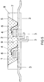
- the chips have separate controllable separate connections 3. In each case one of the terminals 3 is connected via a bonding wire 4 to the chip 1, 2.
- the recess has an inclined wall 7, which serves as a reflector for the primary radiation of the chips 1, 2.
- the recess 9 is filled with a potting compound 5, which contains as main components (80 to 90 wt .-%) typically a silicone casting resin (or Epoxidg discernharz) and phosphor pigments 6 (less than 15 wt .-%). Other minor proportions include methyl ether and Aerosil.
- This narrow common cavity design is possible because the red LED 2 with primary emission at 645 nm is not absorbed or converted by the green phosphor. This shows the importance of a narrow half-width (FWHM below 90 nm, preferably below 80 nm) as an example.
- FWHM narrow half-width
- the disadvantage of this extremely compact solution presented for the first time is the lack of tunability compared to the three-LED solution.
- the illumination system is also suitable in particular for the concept of adaptive illumination, in which the light color or also the brightness of the illumination system can be set according to freely selectable predetermined criteria or adapted to the brightness of the environment in a suitable manner.
Landscapes
- Chemical & Material Sciences (AREA)
- Inorganic Chemistry (AREA)
- Engineering & Computer Science (AREA)
- Materials Engineering (AREA)
- Organic Chemistry (AREA)
- Luminescent Compositions (AREA)
- Led Device Packages (AREA)
Description
- Die Erfindung geht aus von einem hocheffizienten Beleuchtungssystem auf LED-Basis mit verbesserter Farbwiedergabe. Es handelt sich dabei insbesondere um Lumineszenzkonversions-LEDs, die insbesondere voll durchstimmbar sind.
- Ein Konzept für ein hocheffizientes Beleuchtungssystem auf LED-Basis mit verbesserter Farbwiedergabe ist die Dreifarbenmischung. Hierbei wird zur Erzeugung von weiß die Mischung der Grundfarben Rot-Grün-Blau (RGB) herangezogen. Dabei kann eine blaue LED zur teilweisen Konversion zweier Leuchtstoffe, die rot und grün emittieren, herangezogen werden. Die Suche nach einem effizienten Grünleuchtstoff für ein RGB-System steht derzeit im Mittelpunkt, wie beispielsweise der Vorschlag aus
US 6 255 670 zeigt. Alternativ wird eine UV-emittierende LED verwendet, die drei Leuchtstoffe, die jeweils ihre Emission im Roten, Grünen und Blauen haben, angeregt, sieheWO 97/48138 WO 01/41215 - Um die gesamte Lichtausbeute zu steigern, wurde auch ein kompliziertes System unter Einschluss einer vierten LED, die im Bereich 575 bis 605 emittiert, in der
WO 00/19141 - Ein etwas anderes Konzept zeigt die
DE-OS 101 37 042 - Eine interessante Klasse von Leuchtstoffen für derartige Beleuchtungssysteme sind die des Typs Oxinitridosilikat, wie sie an sich unter der Kurzformel MSiON bekannt sind; siehe beispielsweise "On new rare-earth doped M-Si-Al-O-N materials", J. van Krevel, TU Eindhoven 2000, ISBN 90-386-2711-4, Kap. 6. Sie sind mit Tb dotiert. Emission wir erreicht bei Anregung durch 365 nm oder 254 nm.
-
WO 2004/030109 (Art. 54(3)) undEP 1 413 618 (Art. 54(3)) beschreiben ein Beleuchtungssystem, bei dem einer LED mindestens ein Leuchtstoff vorgeschaltet ist. - Es ist Aufgabe der vorliegenden Erfindung, ein Beleuchtungssystem auf LED-Basis mit verbesserter Farbwiedergabe gemäß dem Oberbegriff des Anspruchs 1 bereitzustellen, dessen Farbwiedergabe möglichst hoch ist. Eine weitere Aufgabe ist, ein durchstimmbares Beleuchtungssystem anzugeben.
- Diese Aufgabe wird durch die kennzeichnenden Merkmale des Anspruchs 1 gelöst. Besonders vorteilhafte Ausgestaltungen finden sich in den abhängigen Ansprüchen.
- Für bestimmte Anwendungen ist der Einsatz von RGB-LEDs interessant, die aus drei Chips mit den Emissionsfarben RGB bestehen. Da alle drei Farben durch verschiedene LEDs realisiert sind, können alle drei Komponenten unabhängig voneinander angesteuert werden. Daher ist es mit dieser Art von Beleuchtungssystem möglich nahezu jeden gewünschten Farbort über eine entsprechende Steuerelektronik gezielt einzustellen. Ein Nachteil dieser Lösung ist ein sehr niedriger Farbwiedergabeindex Ra < 50, der sich aufgrund der Schmalbandigkeit der drei Einzelemissionen ergibt. Ein weiterer Nachteil ist, dass die eingesetzte Grün-LED aus technologischen Gründen deutlich weniger effizient ist als die anderen beiden Komponenten, Hinzu kommt, dass der Farbort stark vom Betriebsstrom und der Temperatur abhängt. Derzeitige Technologie (InGaN-LED für blau 430 bis 470 nm bzw. InGa-AIP-LED für gelb > 540 nm insbesondere rot im Bereich 600 bis 700 nm) hat für die Primärstrahlung einer LED im grünen Spektralbereich keine überzeugende Lösung. Der Vorteil der mit Primärstrahlung realisierten RGB-Lösung ist allerdings, dass derartige Beleuchtungssysteme durchstimmbar sind.
- Dagegen werden für Beleuchtungssysteme, bei denen eine hohe Anforderung an die Farbwiedergabe im Vordergrund steht, LEDs verwendet, bei denen ein Teil der primären LED-Emission in längerwelliges Licht, vor allem grün, konvertiert wird. Allerdings ist dieser Aufbau nicht durchstimmbar, weil die sekundäre Komponente nicht unabhängig von der primären Komponente ist.
- Bisher gibt es keinen grün emittierenden Leuchtstoff hoher Effizienz, der gleichzeitig unempfindlich gegen äußere Einflüsse ist.
- Das erfindungsgemäße Beleuchtungssystem nutzt gleichzeitig das Farbmischprinzip aus blau, grün und rot (RGB-Mischung) und das Prinzips der Konversion einer primär von einer LED emittierten Strahlung in längerwelliges Licht durch einen diese Strahlung absorbierenden Leuchtstoff aus, wobei mindestens zwei LEDs verwendet werden, von denen eine erste LED primär im Bereich 340 bis 470 nm (Peakwellenlänge) emittiert, insbesondere bei mindestens 420 nm, und eine zweite LED im roten Bereich bei 600 bis 700 nm (Peakwellenlänge) emittiert, wobei die grüne Komponente dadurch erzeugt wird, dass die Primärstrahlung der ersten LED zumindest teilweise von einem grün emittierenden Leuchtstoff konvertiert wird, wobei als grün emittierender Leuchtstoff ein Leuchtstoff aus der Klasse der Oxinitridosilikate verwendet wird, mit einem Kation M und der grundsätzlichen Formel M(1-c)Si2O2N2:Dc, wobei M als Bestandteil Sr umfast und wobei D mit zweiwertigem Europium dotiert ist, wobei M = Sr, oder M = Sr(1-x-y)BayCax mit x+y < 0,5 verwendet wird, wobei das Oxinitridosilikat vollständig oder überwiegend aus der hochtemperaturstabilen Modifikation HT besteht
- Es wird die Verwendung eines Leuchtstoffs vorgeschlagen, der ein Oxinitridosilikat der Formel MSi2O2N2 (M = Ca, Sr, Ba) darstellt, das mit zweiwertigem Eu aktiviert ist, unter evtl. weiterer Zugabe von Mn als Koaktivator, wobei der Leuchtstoff überwiegend oder allein, also mit mehr als 50 % des Leuchtstoffs, aus der HT-Phase besteht. Diese HT-Modifikation zeichnet sich dadurch aus, dass sie breitbandig anregbar aus, dass sie eine extrem hohe Stabilität gegen äußere Einflüsse besitzt, also bei 150°C keine messbare Degradation zeigt, dass sie eine extrem gute Farbortstabilität unter wechselnden Bedingungen zeigt (zwischen 20 und 100 °C wenig Drift nachweisbar). Weitere Pluspunkte sind seine geringe Absorption im Roten, was besonders bei Leuchtstoffmischungen vorteilhaft ist. Dieser Leuchtstoff wird im folgenden oft Sr-Sion:Eu genannt.
- Bei der Herstellung des neuartigen Leuchtstoffs kommt es vor allem auf eine hohe Temperatur an, der Synthesebereich liegt bei 1300 bis 1600 °C. ein anderer bestimmender Faktor ist die Reaktivität der Ausgangskomponenten. Diese sollte möglichst hoch sein.
- Der aus
EP-PA 02 021 117.8 - Überraschenderweise hat sich nun gezeigt, dass sich die beiden Phasen in ihrer Eignung als Leuchtstoff grundlegend unterscheiden. Während die NT-Phase als Eudotierter Leuchtstoff nur bedingt zu gebrauchen ist, und eher orange-rot emittiert, zeigt die HT-Phase eine hervorragende Eignung als Leuchtstoff, der grün emittiert. Häufig liegt eine Mischung beider Modifikationen vor, die breitbandig beide Emissionen erkennen lässt. Gewünscht ist daher, die HT-Phase möglichst rein, mit mindestens 50 % Anteil, bevorzugt mindestens 70 %, besonders bevorzugt mindestens 85% Anteil herzustellen.
- Dafür ist ein Glühprozess erforderlich, der bei mindestens 1300 °C, aber nicht mehr als 1600 °C durchgeführt wird. Bevorzugt ist ein Temperaturbereich von etwa 1450 bis 1580 °C, da bei geringerer Temperatur zunehmend NT-Phase entsteht und bei höherer Temperatur der Leuchtstoff zunehmend schlechter verarbeitbar ist, und ab etwa 1600 °C als hart gesinterte Keramik oder Schmelze vorliegt. Der optimale Temperaturbereich hängt von der genauen Zusammensetzung und den Eigenschaften der Ausgangsmaterialien ab.
- Besonders wichtig für das Herstellen eines effizienten Leuchtstoffs des Typs Sr-Sion ist ein Ansatz der Ausgangsprodukte, der im wesentlichen stöchiometrisch ist unter Verwendung der Grundkomponenten SiO2, SrCO3 sowie Si3N4. Sr steht hier beispielhaft stellvertretend für M. Die Abweichung sollte insbesondere 10 %, bevorzugt 5 %, des idealen stöchiometrischen Ansatzes nicht überschreiten, wobei auch die etwaige Zugabe eines Schmelzmittels, wie es oft üblich ist, dabei eingeschlossen ist. Besonders bevorzugt ist eine maximale Abweichung von 1 %. Hinzu kommt ein Vorläufer für den Europium-Beitrag der Dotierung, der beispielsweise als Oxid Eu2O3 realisiert wird. Diese Erkenntnis steht im Gegensatz zu der bisherigen Vorgehensweise, die Grundkomponente SiO2 deutlich unterstöchiometrisch zuzugeben. Besonders überraschend ist diese Erkenntnis auch deswegen, weil andere als Leuchtstoff empfohlene Sione wie Ba-Sion gemäß der Lehre von
EP-PA 02 021 117.8 - Ein entsprechender Ansatz für das Sr-Sion MSi2O2N2 verwendet daher 11 bis 13 Gew.-% SiO2, 27 bis 29 Gew.-% Si3N4, Rest SrCO3. Ba- und Ca- Anteile an M werden entsprechend als Carbonat zugesetzt. Europium wird entsprechend der gewünschten Dotierung, beispielsweise als Oxid oder Fluorid, als Ersatz für SrCO3 zugesetzt. Der Ansatz MSi2O2N2 meint dabei auch etwaige Abweichungen von der exakten Stöchiometrie, soweit sie hinsichtlich der Ladungserhaltung ausgeglichen sind.
- Als besonders günstig hat sich erwiesen, dass die Ausgangskomponenten des Wirtsgitters, insbesondere Si3N4, möglichst hohe Reinheit besitzen. Besonders bevorzugt ist daher Si3N4, das aus der flüssigen Phase, ausgehend beispielsweise von Siliziumtetrachlorid, synthetisiert ist. Als kritisch hat sich insbesondere die Verunreinigung mit Wolfram und Kobalt, erwiesen. Hier sollte die Verunreinigung möglichst gering sein, insbesondere sollte sie jeweils kleiner 100 ppm, insbesondere kleiner 50 ppm, sein, bezogen auf diese Vorläufersubstanzen. Des weiteren ist eine möglichst hohe Reaktivität vorteilhaft, sie lässt sich durch die reaktive Oberfläche (BET) quantifizieren. Diese sollte mindestens 6 m2/g betragen, vorteilhaft mindestens 8 m2/g. Auch die Verunreinigung an Aluminium und Calcium, bezogen auf diese Vorläufersubstanz Si3N4, sollte möglichst unter 100 ppm liegen.
- Bei Abweichung von der oben angegebenen Verfahrensführung in bezug auf stöchiometrischen Ansatz und Temperaturführung entstehen als unerwünschte Fremdphasen in zunehmendem Maße Nitridosilikate MxSiyNz wie etwa M2Si5N8, wenn die SiO2-Zugabe zu niedrig angesetzt wird, so dass ein Stickstoffüberschuss entsteht. Obwohl diese Verbindung an sich ein bemerkenswerter Leuchtstoff ist, ist sie in Zusammenhang mit der Synthese des Sr-Sions genauso wie andere Nitridosilikate äußerst störend, weil diese Fremdphasen die grüne Strahlung des Sr-Sions absorbieren und evtl. in die bekannte rote Strahlung der Nitridosilikate umwandeln. Umgekehrt entstehen bei zu hoher SiO2-Zugabe Sr-Silikate wie beispielsweise Sr2SiO4 weil ein Sauerstoffüberschuss entsteht. Beide Fremdphasen absorbieren die nutzbare grüne Emission oder führen zumindest zu Gitterdefekten wie Leerstellen, die die Effizienz des Leuchtstoffs stark beeinträchtigen. Als Anhaltspunkt dient die Richtschnur, dass der Anteil der Fremdphasen möglichst unter 15 %, bevorzugt sogar unter 5 %, liegen soll. Dies korrespondiert im XRD-Spektrum des synthetisierten Leuchtstoffs mit der Forderung, dass beim XRD-Ablenkwinkel 2 Θ im Bereich 25 bis 32° die Intensität aller Fremdphasenpeaks kleiner als 1/3, bevorzugt kleiner als ¼, besonders bevorzugt kleiner als 1/5, der Intensität des die HT-Modifikation kennzeichnenden Hauptpeaks bei etwa 31,8° sein soll. Dies gilt vor allem für die Fremdphasen vom Typ SrxSiyNz, insbesondere Sr2Si5N8.
- Im Falle einer optimierten Verfahrensführung lässt sich zuverlässig eine Quanteneffizienz von 80 bis deutlich über 90 % erzielen. Dagegen wird bei unspezifischer Verfahrensführung die Effizienz typisch im Bereich von höchstens 50 bis 60 % Quanteneffizienz liegen.
- Erfindungsgemäß lässt sich somit ein Leuchtstoff herstellen, der ein Oxinitridosilikat der Formel MSi2O2N2 (M = Ca, Sr, Ba) darstellt, das mit zweiwertigem Eu aktiviert ist, unter evtl. weiterer Zugabe von Mn als Koaktivator, wobei der Leuchtstoff überwiegend oder allein, also zu mehr als 50 % des Leuchtstoffs, bevorzugt zu mehr als 85% des Leuchtstoffs, aus der HT-Phase besteht. Diese HT-Modifikation zeichnet sich dadurch aus, dass sie breitbandig anregbar ist, nämlich in einem weiten Bereich von 50 bis 480 nm, insbesondere 150 bis 480 nm, besonders bevorzugt von 250 bis 470 nm, dass er eine extrem hohe Stabilität gegen äußere Einflüsse besitzt, also bei 150°C an Luft keine messbare Degradation zeigt, und dass er eine extrem gute Farbortstabilität unter wechselnden Bedingungen zeigt. Weitere Pluspunkte sind seine geringe Absorption im Roten, was besonders bei Leuchtstoffmischungen vorteilhaft ist. Dieser Leuchtstoff wird im folgenden oft Sr-Sion:Eu genannt. Ein Überwiegen der HT-Modifikation ist u.a. daran erkennbar, dass der kennzeichnende Peak der NT-Modifikation im XRD-Spektrum bei etwa 28,2 ° eine Intensität von weniger als 1:1, bevorzugt weniger als 1:2, im Vergleich zum Peak mit höchster Intensität aus der Dreiergruppe der Reflexe der HT-Modifikation, die im XRD-Spektrum bei 25 bis 27° liegen, aufweist. Die hier aufgeführten XRD-Spektren beziehen sich jeweils auf eine Anregung durch die bekannte Cu-Kα Linie.
- Bei gleicher Aktivatorkonzentration zeigt dieser Leuchtstoff ein anderes Emissionsverhalten als die NT-Variante gleicher Stöchiometrie. Die Halbwertsbreite der HT-Variante ist im Falle der optimierten HT-Variante wesentlich geringer als bei der einfachen fremdphasen- und defekthaltigen Mischung und liegt im Bereich 70 bis 80 nm, während die einfache Fremdphasen- bzw. defekthaltige Mischung eine Halbwertsbreite von etwa 110 bis 120 nm zeigt. Die dominante Wellenlänge ist bei der HT-Modifikation generell kürzer, typisch 10 bis 20 nm kürzer, als bei einer deutlich fremdphasenhaltigen Probe. Hinzu kommt, dass die Effizienz der hochreinen HT Modifikation typisch um mindestens 20 % höher, teilweise deutlich noch höher, als bei der NT-dominierten oder hoch fremdphasenhaltigen Mischung liegt.
- Ein kennzeichnendes Merkmal eines ausreichend geringen Anteils der NT-Modifikation und Fremdphasen ist eine Halbwertsbreite (FWHM) der Emission von weniger als 90 nm. Denn je geringer der Anteil an Fremdphasen, desto geringer ist der Anteil der spezifischen orange-roten Emission der fremdphasenreichen Modifikation, insbesondere der Nitridosilikat-Fremdphasen Sr-Si-N-Eu wie vor allem Sr2Si5N8:Eu.
- Hilfreich zur Charakterisierung sind neben der verringerten Halbwertsbreite die oben angegebenen typischen Reflexe im XRD-Spekrum, die die andere Kristallstruktur verdeutlichen.
- Der vorherrschende Peak im XRD-Spektrum der HT-Modifikation ist der Peak bei etwa 31.7°. weitere prominente Peaks sind die drei Peaks etwa gleicher Intensität zwischen 25 und 27° (25,3 und 26,0 und 26,3°), wobei der Peak mit kleinster Ablenkung der intensivste ist. ein weiterer intensiver Peak ist 12,6°.
- Dieser Leuchtstoff ist vor allem grün emittierend mit einer Dominanzwellenlänge im Bereich 550 bis 570 nm, insbesondere 555 bis 565 nm.
- Auch eine geringfügige Beimengung der Gruppe AIO als Ersatz der Gruppe SiN im Molekül des Oxinitridosilikats der Formel MSi2O2N2 ist möglich, insbesondere bis maximal 30 % des SiN-Anteils.
- Beide Phasen des Sr-Sion:Eu können analog zu den zwei strukturell unterschiedlichen Wirtsgittermodifikationen kristallisieren und jeweils über die Ansatzstöchiometrie SrSi2O2N2:Eu hergestellt werden. Geringe Abweichungen von dieser Stöchiometrie sind möglich. Die mit Eu dotierten Wirtsgitter lumineszieren überraschenderweise beide bei Anregung im Blauen oder UV, allerdings je nach Wirtsgittermodifikation mit anderer Emissionsfarbe. Die NT-Modifikation zeigt eine orangefarbene Emission, die HT-Modifikation eine grüne Emission bei etwa λdom = 560 nm mit prinzipiell deutlich höherer Effizienz. Je nach Dotiergehalt und Dotiermaterial (Eu oder Eu, Mn) sowie den relativen Anteilen der HT- und NT-Modifikation lässt sich eine gewünschte Eigenschaft des Leuchtstoffs genau einstellen.
- Ein Vorzug der HT-Phase ist die über einen sehr weiten Spektralbereich gleichmäßig gute Anregbarkeit bei nur wenig variierender Quanteneffizienz.
- Außerdem hängt die Lumineszenz der HT-Modifikation in einem weiten Temperaturbereich nur schwach von der Temperatur ab. Damit ist erstmals ein grün emittierender Leuchtstoff, bevorzugt für LED-Anwendungen, gefunden, der ohne besondere Maßnahmen zur Stabilisierung auskommt. Dies zeichnet ihn besonders gegen die bisher als aussichtsreichste Kandidaten angesehenen Leuchtstoffe für diese Aufgabe aus, nämlich Thiogallat-Leuchtstoffe oder Chlorosilikate.
- Die Sionverbindungen mit M = (Sr,Ba), bevorzugt ohne Ba oder mit Ba-Anteil bis zu 10 %, stellen effiziente Leuchtstoffe mit einem weiten Bereich der Emissionsmaxima dar. Diese liegen meist kurzwelliger als bei reinem Sr-Sion, bevorzugt zwischen 520 und 565 nm. Der erreichbare Farbraum lässt sich außerdem durch geringe Beigaben (bevorzugt bis 30 mol-%) an Ca und/oder Zink erweitern; dadurch werden die Emissionsmaxima eher in den langwelligeren Bereich, verglichen mit reinem Sr-Sion, verschoben, sowie durch partiellen Ersatz (bis 25 mol-%) von Si durch Ge und/oder Sn.
- Eine weitere Ausführungsform ist die Teilsubstitution von M, insbesondere Sr, durch drei- oder einwertige Ionen wie Y3+, La3+ oder Li+ bzw. Na+. Bevorzugt ist ein Anteil dieser Ionen von maximal 20 mol-% des M.
- Insbesondere entfaltet dieser Leuchtstoff Vorteile bei der Verwendung in einem Beleuchtungssystem, wobei er als grüner Leuchtstoff bisherige ineffiziente Lösungen für die grüne Komponenten ersetzt. Die Anregung des Leuchtstoffs erfolgt dabei entweder durch eine blaue LED mit hocheffizienter Primärstrahlung, oder auch durch eine UV-LED. Da die grüne Emission relativ breitbandig ist, verglichen mit anderen technologischen Lösungen wie Thiogallaten oder Chlorosilikaten, stellt sich ein deutlich gestiegener Farbwiedergabeindex ein.
- Dieser Leuchtstoff eignet sich besonders gut für die Anwendungen bei vollfarbtauglichen Lumineszenzkonversions-LEDs sowie Lumineszenzkonversions-LEDs mit beliebig einstellbaren Farben auf Basis eine UV-Blau primär emittierenden LED. Die Konversion durch den erfindungsgemäßen Leuchtstoff liefert blaugrün bis grüngelbliche Farben.
- Die Mischverbindungen mit M = (Sr,Ba) stellen effiziente Leuchtstoffe mit einem weiten Bereich der Emissionsmaxima dar. Diese liegen zwischen 520 und 570 nm. der erreichbare Farbraum lässt sich außerdem durch geringe Beigaben (bevorzugt bis 30 mol-%) an Ca und/oder Zink erweitern, sowie durch partiellen Ersatz (bis 25 mol-%) von Si durch Ge und/oder Sn.
- Eine weitere Ausführungsform ist die Teilsubstitution von M, insbesondere Sr, durch drei- oder einwertige Ionen wie La3+ oder Li+. Bevorzugt ist ein Anteil von maximal 20 mol-% des M.
- Bevorzugt lässt sich der erfindungsgemäße Leuchtstoff für Lumineszenzkonversions-LED zur Erzeugung von weißem Licht einsetzen, sei es mit blauer Primärstrahlung, aber auch mit UV-Primärstrahlung, wobei mittels blau und gelbgrün emittierender Leuchtstoffe weißes Licht erzeugt wird. Kandidaten für die blaue Komponente sind an sich bekannt, beispielsweise eignen sich BaMgAl10O17:Eu2+ (bekannt als BAM) oder Ba5SiO4(Cl,Br)6:Eu2+ oder CaLa2S4:Ce3+ oder auch (Sr,Ba,Ca)5(PO4)3Cl:EU2+ (bekannt als SCAP). Als gelbgrüne Komponente eignet sich der erfindungsgemäße Leuchtstoff.
- Zur Farbverbesserung dieses Systems wird zusätzlich ein Rotleuchtstoff eingesetzt. Bevorzugt ist die Anwendung einer zusätzlichen primär rot emittierenden LED. Er wird insbesondere zusammen mit einer blau emittierenden Basis-LED verwendet, besonders geeignet sind ((Y,La,Gd,Lu)2O2S:Eu3+, SrS:Eu2+ oder auch (Ca,Sr)2Si5N8 :Eu2+, insbesondere mit hohem Ca-Anteil.
- Auf diese Weise lassen sich, insbesondere in weiten Bereichen bei warmweißen Lichtfarben entsprechend einer Farbtemperatur von 2200 bis 3500 K, Werte des Farbwiedergabeindex Ra von 85 bis 95 erzielen, ohne dabei die Dimmbarkeit des Beleuchtungssystems einzubüßen.
- Die gefundene Lösung ist also nunmehr beiden Teilaspektlösungen überlegen, da sie eine höhere Effizienz als das bisherige effizienzoptimierte System und eine schlagartig bessere Lösung des dimmbaren Systems ermöglicht. Daher wird insgesamt ein Durchbruch für diese Technologie erzielt.
- Besonders bevorzugt ist ein Beleuchtungssystem in RGB-Technik, das nur nitridbasierte Leuchtstoffe verwendet, indem eine hocheffiziente blaue LED mit dominanter Wellenlänge von 440 bis 465 nm, bevorzugt mit 460 nm Peakwellenlänge, zusammen mit Lumineszenzkonversions-LEDs verwendet. Eine erste Lumineszenzkonversions-LED verwendet eine blaue LED, bevorzugt mit 460 nm Peakwellenlänge, als primäre Lichtquelle, unter Konversion mittels des oben beschriebenen Sr-Sions als grüner Sekundär-Lichtquelle. Eine zweite Lumineszenzkonversions-LED verwendet eine blaue LED, bevorzugt mit etwa 460 nm Peakwellenlänge, als primäre Lichtquelle, unter Konversion mittels eines Nitridosilikats vom Typ (Ca,Sr)2Si5N8:Eu2+ als roter Sekundär-Lichtquelle. Überraschenderweise ergänzen sich diese drei Komponenten nahezu ideal in ihrem Spektrum, so dass die hohe Farbwiedergabe bei hoher Effizienz möglich wird.
- Die technische Realisierung des erfindungsgemäßen Beleuchtungssystems kann auf mehrere Arten erfolgen. Insbesondere sind sog. Multichip-LEDs von Interesse, hier befinden sich die verschiedenen Chips in einem Gehäuse. In aller Regel handelt es sich dabei um zwei oder drei Chips. Prinzipiell sind folgende Realisierungen möglich:
Die erste LED ist in einer ersten Ausführungsform eine primär im Bereich 340 bis 430 nm emittierende UV-LED, die den grünen Leuchtstoff zur sekundären Emission anregt. Die zweite LED ist die rot emittierende LED. Außerdem wird eine dritte LED verwendet, die bevorzugt selbst primär blau emittiert (430 bis 470 nm Peak) oder auch bei der ein blauer Leuchtstoff von einer primär UV emittierenden LED angeregt wird. - In einer zweiten Ausführungsform werden nur zwei LEDs verwendet. Dabei ist die erste LED entweder primär UV emittierend im Bereich 340 bis 420 nm, wobei ihr ein blau emittierender Leuchtstoff und der neuartige grün emittierende Leuchtstoff vorgeschaltet sind. Diese beiden Leuchtstoff konvertieren die UV Strahlung der ersten LED vollständig. Bevorzugt ist aber eine Ausführung, bei der die erste LED eine blau emittierende LED mit Peak im Bereich 430 bis 470 nm ist, der ein neuartiger grün emittierender Leuchtstoff vorgeschaltet ist, der das primäre Licht der LED teilweise in grüne Sekundärstrahlung umwandelt. Die zweite LED ist wieder die rot emittierende LED. Selbstverständlich ist nicht ausgeschlossen, dass auch der rote Anteil durch Konversion einer kürzerwelligen Strahlung erzeugt wird, beispielsweise einer UV-LED oder blauen LED.
- Die hier beschriebenen LEDs können selbstverständlich auch als Gruppen von gleichartigen LEDs verstanden werden.
- Die einzelnen Chips sind dabei lokal mit dem jeweiligen Leuchtstoff versehen. Die einzelnen Chips können sich zu diesem Zweck in verschiedenen Hohlräumen oder Kavitäten oder zusammen in einer einzigen Kavität befinden. Dabei werden die Chips normalerweise bereits in einem Vorprozess mit dem Leuchtstoff versehen. Bei der Lösung mit einer einzigen Kavität oder einer Lösung, bei der der Leuchtstoff physikalisch getrennt vom Chip angeordnet ist, kann das Auftragen des Leuchtstoffs auch erst nach dem Einbau der Chips in das Gehäuse des Beleuchtungssystems erfolgen. Die beschriebenen Leuchtstoffe sind insbesondere für Techniken der chipnahen Konversion geeignet, wie sie an sich in der Literatur bekannt sind, siehe beispielsweise
DE 102 03 795 . - Die Erfindung betrifft weiterhin ein Beleuchtungssystem mit LEDs wie oben beschrieben, wobei das Beleuchtungssystem weiterhin elektronische Komponenten enthält. diese vermitteln beispielsweise die Dimmbarkeit. Eine weitere Aufgabe der Elektronik ist die Ansteuerung einzelner LEDs oder auch Gruppen von LEDs. Diese Funktionen können durch vorbekannte elektronische Elemente realisiert sein.
- Im folgenden soll die Erfindung anhand zweier Ausführungsbeispiele näher erläutert werden. Es zeigen:
- Figur 1
- ein Emissionsspektrum eines Oxinitridosilikats;
- Figur 2
- das Reflektionsspektrum dieses Oxinitridosilikats;
- Figur 3
- ein Beleuchtungssystem mit mehreren Halbleiterbauelementen, das als Lichtquelle für weißes Licht dient (
Fig. 3b ), wobei ein Halbleiterbauelement auch in Vergrößerung (Fig. 3a ) gezeigt ist; - Figur 4
- ein Emissionsspektrum des Halbleiterbauelements aus
Figur 3 ; - Figur 5
- ein zweites Ausführungsbeispiel eines Halbleiterbauelements.
- Ein konkretes Beispiel für den hocheffizienten grün emittierenden Leuchtstoff ist in
Figur 1 gezeigt. Es handelt sich um die Emission des Leuchtstoffs SrSi2N2O2:(10 % Eu2+) in HT-Modifikation, bei dem der Eu-Anteil 10 mol-% der von Sr besetzten Gitterplätze ausmacht. Das Emissionsmaximum liegt bei 545 nm, die mittlere dominante Wellenlänge bei 564 nm (λdom). Der Farbort ist x=0,393; y=0,577. Die Anregung erfolgt bei 460 nm. Die FWHM ist 84 nm. -
Figur 2 zeigt das diffuse Reflexionsspektrum dieses Leuchtstoffs. Es zeigt ein ausgeprägtes Minimum im Bereich unter 430 nm, das somit die gute Anregbarkeit in diesem Bereich demonstriert. - Der Aufbau einer Lichtquelle für weißes Licht ist in
Figur 3a, 3b explizit gezeigt. Die Lichtquelle, sieheFigur 3b , ist ein Halbleiterbauelement 6 vom Typ LED mit einem ersten Chip 1 des Typs InGaN mit einer Peakemissionswellenlänge von beispielsweise 460 nm, sowie einem zweiten Chip 2 vom Typ InGaAlP mit einer Peakemissionswellenlänge von beispielsweise 620 nm und schließlich einem Halbleiterbauelement vom Typ Lumineszenzkonversions-LED mit einem dritten Chip 3 des Typs InGaN mit einer primären Peakemissionswellenlänge von beispielsweise 460 nm. Das Halbleiterbauelement 6 ist mit anderen ähnlichen Elementen in ein lichtundurchlässiges Grundgehäuse 8 eingebettet. Der Leuchtstoff ist das als Ausführungsbeispiel vorgestellte Oxinitridosilikat SrSi2O2N2:Eu(10%), der die primäre Strahlung des Chips 3 vollständig konvertiert und in grüne Strahlung der Peakemission 547 nm mit λdom = 563 nm umwandelt. Diese Lösung hat den großen Vorteil, in einem weiten Bereich von Farbtemperaturen durch Änderung der relativen Intensitäten der drei LEDs per elektronischer Steuerung 7 durchstimmbar zu sein. Ein Vergleich, siehe Tab. 1, mit der bisher zur Verfügung stehenden Lösung mit drei primär emittierende LEDs (RGB, wobei grün durch eine InGaN-LED mit λdom= 526 realisiert wurde) zeigt eindrucksvoll die Überlegenheit der neuen Lösung.Fig. 3a zeigt eine LED 6 in Vergrößerung. -
Figur 4 zeigt die Emission eines derartigen Beleuchtungssystems als spektrale Verteilung (Intensität in willkürlichen Einheiten) über die Wellenlänge (in nm). Die gestrichelte Linie zeigt die alte Lösung (drei primär emittierende LEDs) verglichen zur neuen Lösung (zwei primär emittierende LEDs und eine Lumineszenzkonversions-LED für grün) für eine Farbtemperatur von 4000 K. - Der besondere Vorteil der Verwendung einer langwelligen primären Lichtquelle (450 bis 465 nm) für die grüne Lumineszenzkonversions-LED ist, dass hier Probleme mit Alterung und Degradation von Gehäuse und Harz bzw. Leuchtstoff vermieden werden, so dass eine lange Lebensdauer erzielt wird.
- In einem anderen Ausführungsbeispiel wird als primäre Lichtquelle eine UV-LED (etwa 380 nm) für die grüne Lumineszenzkonversions-LED verwendet, wobei hier Probleme mit Alterung und Degradation von Gehäuse und Harz bzw. Leuchtstoff durch zusätzliche an sich bekannte Maßnahmen möglichst weitgehend vermieden werden müssen wie sorgfältige Wahl des Gehäusematerials, Zugabe UV-resistenter Harzkomponenten. Der große Vorteil dieser Lösung ist die sehr hohe Effizienz von typisch 30 lm/W, die damit erzielbar ist.
Tab. 1: Vergleich des Farbwiedergabeindex Ra sowie des roten Index R9 zwischen weiß emittierenden Halbleiterbauelementen auf Basis der reinen LED-Lösung (alt) und der Lösung mit grüner Lumineszenzkonversions-LED (neu) Farbtemperatur (K) Ra (alt) R9 (alt) Ra (neu) R9 (neu) 2700 38 -23 91 92 3000 38 -37 91 93 4000 43 -71 94 89 5000 36 -87 91 78 6430 51 -99 86 57 - In einem weiteren Ausführungsbeispiel, siehe
Figur 5 , wird als weiß emittierendes Halbleiterbauelement eine Lösung mit zwei LEDs verwendet. Der prinzipielle Aufbau ist ähnlich wie inWO 01/41215 - Die Chips besitzen getrennt steuerbare separate Anschlüsse 3. Jeweils einer der Anschlüsse 3 ist über einen Bonddraht 4 mit dem Chip 1, 2 verbunden. Die Ausnehmung hat eine schräge Wand 7, die als Reflektor für die Primärstrahlung der Chips 1, 2 dient. Die Ausnehmung 9 ist mit einer Vergussmasse 5 gefüllt, die als Hauptbestandteile (80 bis 90 Gew.-%) typisch ein Silikongießharz (oder auch Epoxidgießharz) und Leuchtstoffpigmente 6 (weniger als 15 Gew.-%) enthält. Weitere geringe Anteile entfallen u.a. auf Methylether und Aerosil. Der Leuchtstoff ist das als erstes Ausführungsbeispiel vorgestellte Oxinitridosilikat SrSi2O2N2:Eu(10%) in geringerer Konzentration, der die primäre Strahlung der LED nur teilweise konvertiert und in grüne Strahlung der Peakemission 540 nm, bzw. λdom = 560 nm umwandelt.
- Diese enge Bauform mit gemeinsamer Kavität ist möglich, weil die rote LED 2 mit primärer Emission bei 645 nm vom grünen Leuchtstoff nicht absorbiert bzw. konvertiert wird. Damit zeigt sich die Bedeutung einer engen Halbwertsbreite (FWHM unter 90 nm, bevorzugt unter 80 nm) exemplarisch. Der Nachteil dieser erstmalig vorgestellten extrem kompakten Lösung ist im Vergleich zur Drei-LED-Lösung lediglich die fehlende Durchstimmbarkeit.
- Das Beleuchtungssystem eignet sich insbesondere auch für das Konzept der adaptiven Beleuchtung, bei der sich die Lichtfarbe oder auch die Helligkeit des Beleuchtungssystems nach frei wählbaren vorgegebenen Kriterien einstellen läst oder der Helligkeit der Umgebung in geeigneter Weise anpasst.
Claims (16)
- Beleuchtungssystem auf LED-Basis unter gleichzeitiger Ausnutzung des Farbmischprinzips aus blau, grün und rot (RGB-Mischung) und des Prinzips der Konversion einer primär von einer LED emittierten Strahlung in längerwelliges Licht durch einen diese Strahlung absorbierenden Leuchtstoff, wobei mindestens zwei LEDs verwendet werden, von denen eine erste LED primär im Bereich 340 nm bis 470 nm (Peakwellenlänge), insbesondere mindestens 420 nm, emittiert und eine zweite LED im roten Bereich bei 600 bis 700 nm (Peakwellenlänge) emittiert, dadurch gekennzeichnet, dass die grüne Komponente dadurch erzeugt wird, dass die Primärstrahlung der ersten LED zumindest teilweise von einem grün emittierenden Leuchtstoff konvertiert wird, wobei als grün emittierender Leuchtstoff ein Leuchtstoff aus der Klasse der Oxinitridosilikate verwendet wird, mit einem Kation M und der grundsätzlichen Formel M(1-c)Si2O2N2 : Dc, und wobei M als Bestandteil Sr umfasst und M = Sr allein oder M = Sr(1-x-y)BayCax mit 0 ≤ x+y < 0,5 verwendet wird, und wobei D mit zweiwertigem Europium dotiert ist, und wobei das Oxinitridosilikat vollständig oder überwiegend aus der hochtemperaturstabilen Modifikation HT besteht.
- Beleuchtungssystem nach Anspruch 1, dadurch gekennzeichnet, dass das System Gruppen gleichartiger LEDs enthält.
- Beleuchtungssystem nach Anspruch 1, dadurch gekennzeichnet, dass drei LEDs oder Gruppen von LEDs verwendet werden, wobei die Primärstrahlung der ersten LED vollständig in grüne Sekundäremission umgewandelt wird, wobei eine dritte LED blaues Licht emittiert, insbesondere mit einer Peakwellenlänge im Bereich 430 bis 470 nm.
- Beleuchtungssystem nach Anspruch 1, dadurch gekennzeichnet, dass das System eine Steuerelektronik enthält, die Dimmbarkeit oder gezielte Steuerbarkeit von Eigenschaften des Systems wie die Lichtfarbe vermittelt.
- Beleuchtungssystem nach Anspruch 3, dadurch gekennzeichnet, dass das System eine Steuerelektronik enthält, die die Helligkeit der einzelnen LEDs oder Gruppen von LEDs einzeln regelt, so dass ein durchstimmbares Beleuchtungssystem entsteht für einen Bereich an Farbtemperaturen, der mindestens 1000 K überdeckt innerhalb eines Bandes von 2500 bis 5000 K, mit einem Ra von mindestens 85, insbesondere mindestens 90, für jede gewählte Farbtemperatur innerhalb des gewählten Bereichs.
- Beleuchtungssystem nach Anspruch 1, dadurch gekennzeichnet, dass genau zwei LEDs oder Gruppen von LEDs verwendet werden, wobei die Primärstrahlung der ersten LED nur teilweise in grüne Sekundäremission umgewandelt wird, wobei sowohl der grüne als auch der blaue Beitrag von der ersten LED emittiert wird.
- Beleuchtungssystem nach Anspruch 1, dadurch gekennzeichnet, dass die grüne Sekundäremission eine dominante Wellenlänge im Bereich 550 bis 570 nm hat.
- Beleuchtungssystem nach Anspruch 1, dadurch gekennzeichnet, dass beim Oxinitridosilikat der Anteil des Eu zwischen 0,1 und 20 mol-% von M ausmacht, also 0,001 < c < 0,2.
- Beleuchtungssystem nach Anspruch 1, dadurch gekennzeichnet, dass Sr als M den überwiegenden Anteil stellt und ein Teil von M, insbesondere bis zu 30 mol-%, durch Ba und/oder Ca ersetzt ist.
- Beleuchtungssystem nach Anspruch 1, dadurch gekennzeichnet, dass ein Teil von M bis zu 30 mol-% durch Li und/oder La und/oder Zn und/oder Na und/oder Y ersetzt ist.
- Beleuchtungssystem nach Anspruch 1, dadurch gekennzeichnet, dass ein Teil von Eu bis zu 30 mol-% durch Mn ersetzt ist.
- Beleuchtungssystem nach Anspruch 1, dadurch gekennzeichnet, dass als primäre Strahlungsquelle eine Leuchtdiode auf Basis von InGaN mit einer Peakwellenlänge im Bereich 420 bis 470 nm verwendet wird, die insbesondere ihre Peakwellenlänge im Bereich 440 bis 465 nm hat.
- Beleuchtungssystem nach Anspruch 1, dadurch gekennzeichnet, dass durch die Farbmischung über das RGB-Prinzip ein weiß emittierendes Beleuchtungssystem mit einer Farbtemperatur von 2500 bis 5000 K, insbesondere 3500 bis 5000 K, realisiert wird.
- Beleuchtungssystem nach Anspruch 1, dadurch gekennzeichnet, dass mehrere lichtemittierende Komponenten in einer Kavität angeordnet sind, insbesondere eine Lumineszenzkonversions-LED, die blaue und grüne Anteile der Emission gleichzeitig vermittelt, und eine LED, die rote Anteile der Emission direkt vermittelt.
- Beleuchtungssystem nach Anspruch 1, dadurch gekennzeichnet, dass ein Anteil der NT-Modifikation oder von Fremdphasen so gering ist, daß die Halbwertsbreite des Oxinitridosilikats kleiner 90 nm ist.
- Beleuchtungssystem nach Anspruch 1, dadurch gekennzeichnet, dass das System eine Elektronik zur Ansteuerung einzelner LEDs oder auch Gruppen von LEDs enthält.
Applications Claiming Priority (2)
| Application Number | Priority Date | Filing Date | Title |
|---|---|---|---|
| DE10344332 | 2003-09-24 | ||
| PCT/DE2004/002135 WO2005030903A1 (de) | 2003-09-24 | 2004-09-24 | Hocheffizientes beleuchtungssystem auf led-basis mit verbesserter farbwiedergabe |
Publications (2)
| Publication Number | Publication Date |
|---|---|
| EP1670875A1 EP1670875A1 (de) | 2006-06-21 |
| EP1670875B1 true EP1670875B1 (de) | 2019-08-14 |
Family
ID=34384255
Family Applications (1)
| Application Number | Title | Priority Date | Filing Date |
|---|---|---|---|
| EP04786851.8A Expired - Lifetime EP1670875B1 (de) | 2003-09-24 | 2004-09-24 | Hocheffizientes beleuchtungssystem auf led-basis mit verbesserter farbwiedergabe |
Country Status (7)
| Country | Link |
|---|---|
| US (1) | US7825574B2 (de) |
| EP (1) | EP1670875B1 (de) |
| JP (1) | JP4457110B2 (de) |
| KR (1) | KR101131648B1 (de) |
| CN (1) | CN1886483B (de) |
| TW (1) | TWI350009B (de) |
| WO (1) | WO2005030903A1 (de) |
Families Citing this family (41)
| Publication number | Priority date | Publication date | Assignee | Title |
|---|---|---|---|---|
| EP2275512B1 (de) * | 2003-09-24 | 2012-07-25 | Osram AG | Grün emittierende LED |
| TW200523340A (en) * | 2003-09-24 | 2005-07-16 | Patent Treuhand Ges Fur Elek Sche Gluhlampen Mbh | Hochefeizienter leuchtstoff |
| US7066623B2 (en) * | 2003-12-19 | 2006-06-27 | Soo Ghee Lee | Method and apparatus for producing untainted white light using off-white light emitting diodes |
| DE102006016548B9 (de) | 2005-04-15 | 2021-12-16 | Osram Gmbh | Blau bis Gelb-Orange emittierender Leuchtstoff und Lichtquelle mit derartigem Leuchtstoff |
| WO2007070821A2 (en) * | 2005-12-13 | 2007-06-21 | Ilight Technologies, Inc. | Illumination device with hue transformation |
| CN101331618A (zh) * | 2005-12-14 | 2008-12-24 | 皇家飞利浦电子股份有限公司 | 产生期望色点的光的半导体光源和方法 |
| US20090033201A1 (en) * | 2006-02-02 | 2009-02-05 | Mitsubishi Chemical Corporation | Complex oxynitride phosphor, light-emitting device using same, image display, illuminating device, phosphor-containing composition and complex oxynitride |
| DE102006008300A1 (de) | 2006-02-22 | 2007-08-30 | Patent-Treuhand-Gesellschaft für elektrische Glühlampen mbH | Leuchtstoff und Lichtquelle mit derartigem Leuchtstoff sowie Herstellverfahren für den Leuchtstoff |
| KR100828891B1 (ko) | 2006-02-23 | 2008-05-09 | 엘지이노텍 주식회사 | Led 패키지 |
| DK176593B1 (da) | 2006-06-12 | 2008-10-13 | Akj Inv S V Allan Krogh Jensen | Intelligent LED baseret lyskilde til erstatning af lysstofrör |
| CN101106856B (zh) * | 2006-07-10 | 2012-01-25 | 东芝照明技术株式会社 | 照明装置 |
| EP2087530A1 (de) * | 2006-11-10 | 2009-08-12 | Philips Intellectual Property & Standards GmbH | Beleuchtungssystem mit einem monolithischen keramischen lumineszenzumwandler |
| EP2103187B1 (de) * | 2006-12-12 | 2010-05-26 | Inverto NV | Led-beleuchtung mit kontinuierlicher und einstellbarer farbtemperatur (ct) unter aufrechterhaltung eines hohen cri |
| KR100946015B1 (ko) * | 2007-01-02 | 2010-03-09 | 삼성전기주식회사 | 백색 발광장치 및 이를 이용한 lcd 백라이트용 광원모듈 |
| DE102007010244A1 (de) * | 2007-02-02 | 2008-08-07 | Osram Opto Semiconductors Gmbh | Anordnung und Verfahren zur Erzeugung von Mischlicht |
| US7857994B2 (en) | 2007-05-30 | 2010-12-28 | GE Lighting Solutions, LLC | Green emitting phosphors and blends thereof |
| WO2009117148A2 (en) * | 2008-03-21 | 2009-09-24 | Nanogram Corporation | Metal silicon nitride or metal silicon oxynitride submicron phosphor particles and methods for synthesizing these phosphors |
| KR100924912B1 (ko) * | 2008-07-29 | 2009-11-03 | 서울반도체 주식회사 | 웜화이트 발광장치 및 그것을 포함하는 백라이트 모듈 |
| JP5308773B2 (ja) * | 2008-10-30 | 2013-10-09 | スタンレー電気株式会社 | 半導体発光装置 |
| JP5342867B2 (ja) * | 2008-12-19 | 2013-11-13 | スタンレー電気株式会社 | 半導体発光装置及び駆動方法 |
| KR101396583B1 (ko) | 2009-09-14 | 2014-05-20 | 서울반도체 주식회사 | 웜화이트 발광장치 및 그것을 포함하는 백라이트 모듈 |
| JP2011071272A (ja) | 2009-09-25 | 2011-04-07 | Toshiba Corp | 半導体発光装置及びその製造方法 |
| WO2011044931A1 (de) * | 2009-10-14 | 2011-04-21 | Osram Gesellschaft mit beschränkter Haftung | LEUCHTVORRICHTUNG ZUR ERZEUGUNG EINES WEIßEN MISCHLICHTS |
| US8395312B2 (en) * | 2010-04-19 | 2013-03-12 | Bridgelux, Inc. | Phosphor converted light source having an additional LED to provide long wavelength light |
| TW201202391A (en) * | 2010-07-14 | 2012-01-16 | Forward Electronics Co Ltd | Phosphor composition for AC LED and AC LED manufactured by using the same |
| KR101225002B1 (ko) * | 2010-09-27 | 2013-01-22 | 삼성전자주식회사 | 형광체 및 이의 제조방법 |
| US8912554B2 (en) | 2011-06-08 | 2014-12-16 | Micron Technology, Inc. | Long wavelength light emitting device with photoluminescence emission and high quantum efficiency |
| KR101772588B1 (ko) * | 2011-08-22 | 2017-09-13 | 한국전자통신연구원 | 클리어 컴파운드 에폭시로 몰딩한 mit 소자 및 그것을 포함하는 화재 감지 장치 |
| US8919975B2 (en) * | 2011-11-09 | 2014-12-30 | Cree, Inc. | Lighting device providing improved color rendering |
| CN104080886B (zh) * | 2012-06-27 | 2017-05-24 | 国立研究开发法人物质·材料研究机构 | 荧光体及其制备方法、发光装置及图像显示装置 |
| CN105556262A (zh) * | 2013-02-14 | 2016-05-04 | 曾海山 | 用于环境光条件下的光学测量的方法和设备 |
| AT14515U1 (de) | 2013-07-23 | 2015-12-15 | Tridonic Jennersdorf Gmbh | LED-Modul mit hohem Farbwiedergabeindex |
| DE102014205705B4 (de) | 2014-03-27 | 2020-11-05 | Carl Zeiss Industrielle Messtechnik Gmbh | Leuchttisch geeignet für Anwendungen in der Metrologie sowie Koordinatenmessgerät mit einem solchen Leuchttisch |
| JP2014150293A (ja) * | 2014-05-30 | 2014-08-21 | Mitsubishi Electric Corp | 発光装置 |
| US9799804B2 (en) | 2014-10-28 | 2017-10-24 | Matrix Lighting Ltd. | Light-emitting device with near full spectrum light output |
| US10090434B2 (en) | 2015-02-26 | 2018-10-02 | Apple Inc. | Illumination device having dual-emitting light emitting diode (LED) die structures |
| CN105368451B (zh) * | 2015-11-26 | 2017-07-28 | 华东师范大学 | 一种荧光增强的氧氮化物发光材料及其制备方法 |
| DE102016206524A1 (de) | 2016-04-19 | 2017-10-19 | Osram Gmbh | LED zur Emission von Beleuchtungsstrahlung |
| DE102016210236B4 (de) | 2016-06-09 | 2019-04-18 | Carl Zeiss Industrielle Messtechnik Gmbh | Verfahren und Koordinatenmessgerät zur metrologischen Vermessung von Werkstücken mit Hilfe eines Leuchttischs |
| DE102017203391B4 (de) | 2017-03-02 | 2025-05-08 | Carl Zeiss Industrielle Messtechnik Gmbh | Verfahren und Koordinatenmessgerät zur metrologischen Vermessung von Werkstücken mit Hilfe eines Displays als Bestandteil eines Leuchttisches |
| CN108485667B (zh) * | 2018-03-28 | 2020-09-22 | 青岛科技大学 | 一种新型的发光颜色可调至白光的荧光粉及其制备方法 |
Family Cites Families (24)
| Publication number | Priority date | Publication date | Assignee | Title |
|---|---|---|---|---|
| US4897319A (en) * | 1988-07-19 | 1990-01-30 | Planar Systems, Inc. | TFEL device having multiple layer insulators |
| JPH11510968A (ja) | 1996-06-11 | 1999-09-21 | フィリップス エレクトロニクス ネムローゼ フェンノートシャップ | 紫外発光ダイオード及び紫外励起可視光放射蛍光体を含む可視発光ディスプレイ及び該デバイスの製造方法 |
| US6255670B1 (en) | 1998-02-06 | 2001-07-03 | General Electric Company | Phosphors for light generation from light emitting semiconductors |
| US6158882A (en) | 1998-06-30 | 2000-12-12 | Emteq, Inc. | LED semiconductor lighting system |
| TW417842U (en) | 1998-09-28 | 2001-01-01 | Koninkl Philips Electronics Nv | Lighting system |
| US6495964B1 (en) | 1998-12-18 | 2002-12-17 | Koninklijke Philips Electronics N.V. | LED luminaire with electrically adjusted color balance using photodetector |
| EP1142033A1 (de) | 1999-09-27 | 2001-10-10 | LumiLeds Lighting U.S., LLC | Weisslicht emittierende diodenvorrichtung mittels vollständiger phosphor-umwandlung |
| US6686691B1 (en) | 1999-09-27 | 2004-02-03 | Lumileds Lighting, U.S., Llc | Tri-color, white light LED lamps |
| EP1104799A1 (de) | 1999-11-30 | 2001-06-06 | Patent-Treuhand-Gesellschaft für elektrische Glühlampen mbH | Rotstrahlendes lumineszentes Material |
| US6513949B1 (en) | 1999-12-02 | 2003-02-04 | Koninklijke Philips Electronics N.V. | LED/phosphor-LED hybrid lighting systems |
| DE19963806C2 (de) | 1999-12-30 | 2002-02-07 | Osram Opto Semiconductors Gmbh | Verfahren zum Herstellen einer Leuchtdioden-Weißlichtquelle, Verwendung einer Kunststoff-Preßmasse zum Herstellen einer Leuchtioden-Weißlichtquelle und oberflächenmontierbare Leuchtdioden-Weißlichtquelle |
| DE60030541T2 (de) * | 2000-01-06 | 2007-08-30 | Koninklijke Philips Electronics N.V. | Leuchte und leuchttafeln |
| JP2002076434A (ja) | 2000-08-28 | 2002-03-15 | Toyoda Gosei Co Ltd | 発光装置 |
| US6411046B1 (en) | 2000-12-27 | 2002-06-25 | Koninklijke Philips Electronics, N. V. | Effective modeling of CIE xy coordinates for a plurality of LEDs for white LED light control |
| DE10105800B4 (de) | 2001-02-07 | 2017-08-31 | Osram Gmbh | Hocheffizienter Leuchtstoff und dessen Verwendung |
| US6632379B2 (en) * | 2001-06-07 | 2003-10-14 | National Institute For Materials Science | Oxynitride phosphor activated by a rare earth element, and sialon type phosphor |
| DE10137042A1 (de) | 2001-07-31 | 2003-02-20 | Patent Treuhand Ges Fuer Elektrische Gluehlampen Mbh | Planare Lichtquelle auf LED-Basis |
| DE10147040A1 (de) | 2001-09-25 | 2003-04-24 | Patent Treuhand Ges Fuer Elektrische Gluehlampen Mbh | Beleuchtungseinheit mit mindestens einer LED als Lichtquelle |
| DE10153615C1 (de) | 2001-10-31 | 2003-07-24 | Osram Opto Semiconductors Gmbh | Verfahren zur Herstellung von elektronischen Bauteilen |
| DE10203795B4 (de) | 2002-01-31 | 2021-12-09 | OSRAM Opto Semiconductors Gesellschaft mit beschränkter Haftung | Verfahren zur Herstellung eines Halbleiterbauelements |
| CN100430456C (zh) | 2002-03-22 | 2008-11-05 | 日亚化学工业株式会社 | 氮化物荧光体,其制造方法及发光装置 |
| EP1413618A1 (de) | 2002-09-24 | 2004-04-28 | Osram Opto Semiconductors GmbH | Lumineszentes Material, insbesondere zur Anwendung in Leuchtdioden |
| US6717353B1 (en) | 2002-10-14 | 2004-04-06 | Lumileds Lighting U.S., Llc | Phosphor converted light emitting device |
| ATE329479T1 (de) | 2002-10-14 | 2006-06-15 | Koninkl Philips Electronics Nv | Lichtemittierendes bauelement mit einem eu(ii)- aktivierten leuchtstoff |
-
2004
- 2004-09-24 KR KR1020067007851A patent/KR101131648B1/ko not_active Expired - Lifetime
- 2004-09-24 EP EP04786851.8A patent/EP1670875B1/de not_active Expired - Lifetime
- 2004-09-24 US US10/574,021 patent/US7825574B2/en active Active
- 2004-09-24 JP JP2006527270A patent/JP4457110B2/ja not_active Expired - Lifetime
- 2004-09-24 TW TW093128944A patent/TWI350009B/zh not_active IP Right Cessation
- 2004-09-24 WO PCT/DE2004/002135 patent/WO2005030903A1/de not_active Ceased
- 2004-09-24 CN CN2004800347223A patent/CN1886483B/zh not_active Expired - Lifetime
Non-Patent Citations (1)
| Title |
|---|
| None * |
Also Published As
| Publication number | Publication date |
|---|---|
| US7825574B2 (en) | 2010-11-02 |
| TW200518366A (en) | 2005-06-01 |
| CN1886483A (zh) | 2006-12-27 |
| CN1886483B (zh) | 2010-06-16 |
| US20070069643A1 (en) | 2007-03-29 |
| JP4457110B2 (ja) | 2010-04-28 |
| KR20060115731A (ko) | 2006-11-09 |
| EP1670875A1 (de) | 2006-06-21 |
| KR101131648B1 (ko) | 2012-03-28 |
| WO2005030903A1 (de) | 2005-04-07 |
| TWI350009B (en) | 2011-10-01 |
| JP2007507065A (ja) | 2007-03-22 |
Similar Documents
| Publication | Publication Date | Title |
|---|---|---|
| EP1670875B1 (de) | Hocheffizientes beleuchtungssystem auf led-basis mit verbesserter farbwiedergabe | |
| EP1664239B1 (de) | Weiss emittierende led mit definierter farbtemperatur | |
| DE60307415T2 (de) | Fotolumineszierende stoffe für leuchtdioden, und leuchtdiode | |
| EP2264762B1 (de) | Beleuchtungseinheit mit mindestens einer LED als Lichtquelle | |
| EP1987114B1 (de) | Leuchtstoff und lichtquelle mit derartigem leuchststoff sowie herstellverfahren für den leuchtstoff | |
| EP1352431B2 (de) | Lichtquelle mit einem lichtemittlierenden element | |
| DE102007035592B4 (de) | Temperaturstabiler Leuchtstoff, Verwendung eines Leuchtstoffs und Verfahren zur Herstellung eines Leuchtstoffs | |
| DE10241140A1 (de) | Beleuchtungseinheit mit mindestens einer LED als Lichtquelle | |
| EP1670876B1 (de) | Hocheffizienter leuchtstoff | |
| EP2275512B1 (de) | Grün emittierende LED | |
| DE10360546A1 (de) | Leuchtstoff und Lichtquelle mit derartigem Leuchtstoff | |
| DE202004021351U1 (de) | Licht emittierende Vorrichtung | |
| WO2006012833A2 (de) | Lichtquelle mit niedriger farbtemperatur | |
| WO2006081803A1 (de) | Gelb emittierender leuchtstoff und lichtquelle mit derartigem leuchtstoff | |
| DE102006016548B4 (de) | Blau bis Gelb-Orange emittierender Leuchtstoff und Lichtquelle mit derartigem Leuchtstoff | |
| EP1966345B1 (de) | Rot emittierender leuchtstoff und lichtquelle mit einem derartigen leuchtstoff | |
| DE102004051395A1 (de) | Hocheffizienter stabiler Oxinitrid-Leuchtstoff | |
| EP2491095B1 (de) | Leuchtstoff und lichtquelle mit derartigem leuchtstoff | |
| DE112019001792B4 (de) | Leuchtstoff und beleuchtungsvorrichtung | |
| DE102005037455A1 (de) | Weißlicht-Leuchtdiode | |
| DE112009001977T5 (de) | Verfahren zur Herstellung eines ß-SiAION-Leuchtstoffs |
Legal Events
| Date | Code | Title | Description |
|---|---|---|---|
| PUAI | Public reference made under article 153(3) epc to a published international application that has entered the european phase |
Free format text: ORIGINAL CODE: 0009012 |
|
| 17P | Request for examination filed |
Effective date: 20060322 |
|
| AK | Designated contracting states |
Kind code of ref document: A1 Designated state(s): BE DE FR GB IT NL |
|
| DAX | Request for extension of the european patent (deleted) | ||
| RBV | Designated contracting states (corrected) |
Designated state(s): BE DE FR GB IT NL |
|
| RIN1 | Information on inventor provided before grant (corrected) |
Inventor name: BRUNNER, HERBERT Inventor name: FIEDLER, TIM Inventor name: ZACHAU, MARTIN Inventor name: JERMANN, FRANK |
|
| RAP1 | Party data changed (applicant data changed or rights of an application transferred) |
Owner name: OSRAM OPTO SEMICONDUCTORS GMBH Owner name: PATENT-TREUHAND-GESELLSCHAFT FUER ELEKTRISCHE GLUE |
|
| RAP1 | Party data changed (applicant data changed or rights of an application transferred) |
Owner name: OSRAM OPTO SEMICONDUCTORS GMBH Owner name: PATENT-TREUHAND-GESELLSCHAFT FUER ELEKTRISCHE GLUE |
|
| 17Q | First examination report despatched |
Effective date: 20120319 |
|
| STAA | Information on the status of an ep patent application or granted ep patent |
Free format text: STATUS: EXAMINATION IS IN PROGRESS |
|
| GRAP | Despatch of communication of intention to grant a patent |
Free format text: ORIGINAL CODE: EPIDOSNIGR1 |
|
| STAA | Information on the status of an ep patent application or granted ep patent |
Free format text: STATUS: GRANT OF PATENT IS INTENDED |
|
| INTG | Intention to grant announced |
Effective date: 20190308 |
|
| GRAS | Grant fee paid |
Free format text: ORIGINAL CODE: EPIDOSNIGR3 |
|
| GRAA | (expected) grant |
Free format text: ORIGINAL CODE: 0009210 |
|
| STAA | Information on the status of an ep patent application or granted ep patent |
Free format text: STATUS: THE PATENT HAS BEEN GRANTED |
|
| AK | Designated contracting states |
Kind code of ref document: B1 Designated state(s): BE DE FR GB IT NL |
|
| REG | Reference to a national code |
Ref country code: GB Ref legal event code: FG4D Free format text: NOT ENGLISH |
|
| REG | Reference to a national code |
Ref country code: DE Ref legal event code: R096 Ref document number: 502004015819 Country of ref document: DE |
|
| RAP2 | Party data changed (patent owner data changed or rights of a patent transferred) |
Owner name: PATENT-TREUHAND-GESELLSCHAFT FUER ELEKTRISCHE GLUE Owner name: OSRAM OPTO SEMICONDUCTORS GMBH |
|
| REG | Reference to a national code |
Ref country code: NL Ref legal event code: MP Effective date: 20190814 |
|
| PG25 | Lapsed in a contracting state [announced via postgrant information from national office to epo] |
Ref country code: NL Free format text: LAPSE BECAUSE OF FAILURE TO SUBMIT A TRANSLATION OF THE DESCRIPTION OR TO PAY THE FEE WITHIN THE PRESCRIBED TIME-LIMIT Effective date: 20190814 |
|
| PG25 | Lapsed in a contracting state [announced via postgrant information from national office to epo] |
Ref country code: IT Free format text: LAPSE BECAUSE OF FAILURE TO SUBMIT A TRANSLATION OF THE DESCRIPTION OR TO PAY THE FEE WITHIN THE PRESCRIBED TIME-LIMIT Effective date: 20190814 |
|
| REG | Reference to a national code |
Ref country code: DE Ref legal event code: R097 Ref document number: 502004015819 Country of ref document: DE |
|
| PLBE | No opposition filed within time limit |
Free format text: ORIGINAL CODE: 0009261 |
|
| STAA | Information on the status of an ep patent application or granted ep patent |
Free format text: STATUS: NO OPPOSITION FILED WITHIN TIME LIMIT |
|
| 26N | No opposition filed |
Effective date: 20200603 |
|
| REG | Reference to a national code |
Ref country code: BE Ref legal event code: MM Effective date: 20190930 |
|
| PG25 | Lapsed in a contracting state [announced via postgrant information from national office to epo] |
Ref country code: BE Free format text: LAPSE BECAUSE OF NON-PAYMENT OF DUE FEES Effective date: 20190930 |
|
| GBPC | Gb: european patent ceased through non-payment of renewal fee |
Effective date: 20191114 |
|
| PG25 | Lapsed in a contracting state [announced via postgrant information from national office to epo] |
Ref country code: GB Free format text: LAPSE BECAUSE OF NON-PAYMENT OF DUE FEES Effective date: 20191114 |
|
| PG25 | Lapsed in a contracting state [announced via postgrant information from national office to epo] |
Ref country code: FR Free format text: LAPSE BECAUSE OF NON-PAYMENT OF DUE FEES Effective date: 20191014 |
|
| PGFP | Annual fee paid to national office [announced via postgrant information from national office to epo] |
Ref country code: DE Payment date: 20230920 Year of fee payment: 20 |
|
| REG | Reference to a national code |
Ref country code: DE Ref legal event code: R071 Ref document number: 502004015819 Country of ref document: DE |