EP1664239B1 - Weiss emittierende led mit definierter farbtemperatur - Google Patents
Weiss emittierende led mit definierter farbtemperatur Download PDFInfo
- Publication number
- EP1664239B1 EP1664239B1 EP04786854A EP04786854A EP1664239B1 EP 1664239 B1 EP1664239 B1 EP 1664239B1 EP 04786854 A EP04786854 A EP 04786854A EP 04786854 A EP04786854 A EP 04786854A EP 1664239 B1 EP1664239 B1 EP 1664239B1
- Authority
- EP
- European Patent Office
- Prior art keywords
- led according
- led
- phosphor
- mol
- emission
- Prior art date
- Legal status (The legal status is an assumption and is not a legal conclusion. Google has not performed a legal analysis and makes no representation as to the accuracy of the status listed.)
- Expired - Lifetime
Links
Images


Classifications
-
- C—CHEMISTRY; METALLURGY
- C09—DYES; PAINTS; POLISHES; NATURAL RESINS; ADHESIVES; COMPOSITIONS NOT OTHERWISE PROVIDED FOR; APPLICATIONS OF MATERIALS NOT OTHERWISE PROVIDED FOR
- C09K—MATERIALS FOR MISCELLANEOUS APPLICATIONS, NOT PROVIDED FOR ELSEWHERE
- C09K11/00—Luminescent materials, e.g. electroluminescent or chemiluminescent
- C09K11/08—Luminescent materials, e.g. electroluminescent or chemiluminescent containing inorganic luminescent materials
- C09K11/77—Luminescent materials, e.g. electroluminescent or chemiluminescent containing inorganic luminescent materials containing rare earth metals
- C09K11/7728—Luminescent materials, e.g. electroluminescent or chemiluminescent containing inorganic luminescent materials containing rare earth metals containing europium
- C09K11/77347—Silicon Nitrides or Silicon Oxynitrides
-
- H—ELECTRICITY
- H10—SEMICONDUCTOR DEVICES; ELECTRIC SOLID-STATE DEVICES NOT OTHERWISE PROVIDED FOR
- H10W—GENERIC PACKAGES, INTERCONNECTIONS, CONNECTORS OR OTHER CONSTRUCTIONAL DETAILS OF DEVICES COVERED BY CLASS H10
- H10W72/00—Interconnections or connectors in packages
- H10W72/851—Dispositions of multiple connectors or interconnections
- H10W72/874—On different surfaces
- H10W72/884—Die-attach connectors and bond wires
-
- H—ELECTRICITY
- H10—SEMICONDUCTOR DEVICES; ELECTRIC SOLID-STATE DEVICES NOT OTHERWISE PROVIDED FOR
- H10W—GENERIC PACKAGES, INTERCONNECTIONS, CONNECTORS OR OTHER CONSTRUCTIONAL DETAILS OF DEVICES COVERED BY CLASS H10
- H10W90/00—Package configurations
- H10W90/701—Package configurations characterised by the relative positions of pads or connectors relative to package parts
- H10W90/751—Package configurations characterised by the relative positions of pads or connectors relative to package parts of bond wires
- H10W90/756—Package configurations characterised by the relative positions of pads or connectors relative to package parts of bond wires between a chip and a stacked lead frame, conducting package substrate or heat sink
Definitions
- the invention is based on an LED with a defined, in particular low color temperature. This is understood to mean a color temperature in the range 2300 to 7000 K. In particular, it is the range 2700 to 3300 K.
- Oxinitrides of various stoichiometry are already known as phosphors for white LED application. Frequently, at least one of the metals Ca, Sr, Ba is used as the cation. These phosphors are primarily intended for daylight applications.
- Simple LEDs which have set themselves the goal of warm white light colors, are based on UV chips. Due to the large energy difference between the UV range and the short-wave visible range (blue) and the UV-related, due to the higher energy, radiation-induced faster aging of the housing and the phosphor coating these LEDs achieve neither the life nor the efficiency of neutral white LEDs, as they are so far available on the basis of blue-emitting chips.
- RGB LEDs based on luminescence conversion LEDs with sulfide and thiogallate phosphors, see for example WO 01/24229 . It has been shown that the phosphor proposed therein does not meet the requirements with regard to long-term stability and efficiency when using high-performance chips which reach a high operating temperature.
- the sulfides are chemical unstable to moisture and the thiogallates proposed there show a pronounced temperature quenching.
- the known sulfide phosphors Upon contact with water, the known sulfide phosphors also decompose to form toxic gases such as hydrogen sulfide.
- Oxinitridosilicate phosphors are known per se under the abbreviation MSiON; see for example “ On new rare-earth doped M-Si-Al-ON materials ", J. Van Krevel, Eindhoven University of Technology 2000, ISBN 90-386-2711-4, chapter 6 , they are endowed with Tb. Emission we achieved when excited by 365 nm or 254 nm.
- This HT modification is characterized by the fact that it can be excited broadband excitation, namely in a wide range of 200 to 480 nm that it has an extremely high stability to external influences, ie at 150 ° C shows no measurable degradation, and that they an extremely good color stability under changing conditions shows (between 20 and 100 ° C little drift detectable).
- This phosphor is often called Sr-sion: Eu in the following.
- This phosphor is mainly green emitting with a dominant wavelength in the range of 550 to 570 nm.
- the synthesis range is 1300 to 1600 ° C.
- Another determining factor is the reactivity of the starting components. This should be as high as possible.
- this phosphor can be efficiently excited by an LED, especially of the InGaN type.
- the two phases differ fundamentally in their suitability as a phosphor. While the NT phase is practically unusable as an Eudotierter phosphor, and only slightly orange-red emitted, the HT phase shows excellent suitability as a phosphor that emits green. Normally, there is a mixture that allows broadband detection of both emissions. It is therefore crucial to produce the HT phase as pure as possible, with at least 50% proportion, preferably at least 70%, particularly preferably at least 85% proportion.
- annealing process that is performed at a minimum of 1300 ° C but not more than 1600 ° C.
- Preference is given to a temperature range of about 1450 to 1580 ° C, since at lower temperature increasingly NT phase is formed and at higher temperature, the phosphor is increasingly difficult to process, and is present from about 1600 ° C as a hard sintered ceramic or melt.
- the optimum temperature range depends on the exact composition and properties of the starting materials.
- Sr-Sion phosphor is an approach of the starting materials, which is substantially stoichiometric using the basic components SiO 2 , SrCO 3 and Si 3 N 4 .
- Sr is hereby exemplified by M.
- the deviation should in particular not exceed 10%, preferably 5%, of the ideal stoichiometric approach, whereby also the possible addition of a flux, as is often the case, is included.
- Particularly preferred is a maximum deviation of 1%.
- the europium contribution of the doping which is realized, for example, as oxide Eu 2 O 3 .
- the basic component of SiO 2 clearly substoichiometric admit.
- This finding is also particularly surprising because other sions, such as Ba-sion, recommended as phosphor are to be produced precisely in the SiO 2 subcutie according to the teaching of EP-PA 02 021 117.8.
- a corresponding approach for the Sr sion MSi 2 O 2 N 2 therefore uses 11 to 13 wt .-% SiO 2 , 27 to 29 wt .-% Si 3 N 4 , balance SrCO 3 .
- Ba and Ca fractions of M are added as carbonate accordingly.
- Europium is added according to the desired doping, for example as oxide or fluoride, as a replacement for SrCO 3 .
- the approach MSi 2 O 2 N 2 also means any deviations from the exact stoichiometry, as far as they are balanced in terms of charge retention.
- the starting components of the host lattice in particular Si 3 N 4 , have the highest possible purity. Therefore, Si 3 N 4 , which is synthesized from the liquid phase, starting, for example, from silicon tetrachloride, is particularly preferred.
- the contamination with tungsten and cobalt has proven to be critical.
- the impurity should be as low as possible, in particular, it should be less than 100 ppm, in particular less than 50 ppm, based on these precursors.
- the highest possible reactivity is advantageous, it can be quantified by the reactive surface (BET). This should be at least 6 m 2 / g, advantageously at least 8 m 2 / g.
- the contamination of aluminum and calcium, based on this precursor Si 3 N 4 should be as possible below 100 ppm.
- this compound is a notable phosphor per se, it is very disturbing in the context of Sr-sion synthesis, as are other nitridosilicates, because these foreign phases absorb the Sr-sion green radiation and eventually convert it to the known red radiation of the nitridosilicates , Conversely, if too much SiO 2 is added, Sr silicates such as, for example, Sr 2 SiO 4 are formed because an excess of oxygen is formed.
- Both foreign phases absorb the usable green emission or at least lead to lattice defects such as vacancies, which severely impair the efficiency of the phosphor.
- the proportion of foreign phases should be less than 15%, preferably even less than 5%. This corresponds in the XRD spectrum of the synthesized phosphor with the requirement that the XRD deflection angle 2 ⁇ in the area 25 to 32 °, the intensity of all foreign phase peaks less than 1/3, preferably less than%, more preferably less than 1/5, the intensity of the main modification marking the HT-modification should be at about 31.8 °. This is especially true for the foreign phases of the type SrxSiyNz, in particular Sr2Si5N8.
- This HT modification is characterized by the fact that it can be excited broadband, in particular in a wide range of 250 to 480 nm, that it has an extremely high stability to external influences, ie at 150 ° C in air no measurable degradation shows that he shows an extremely good color stability in changing conditions. Other pluses are its low absorption in the red, which is particularly advantageous in phosphor mixtures.
- This phosphor is often called Sr-sion: Eu in the following.
- a predominance of the HT modification is evident inter alia from the fact that the characteristic peak of the NT modification in the XRD spectrum at about 28.2 ° an intensity of less than 1: 1, preferably less than 1: 2, compared to the peak with highest intensity from the triad of reflections of HT modification, which are in the XRD spectrum at 25 to 27 °, has.
- the XRD spectra listed here each refer to an excitation by the known Cu-K ⁇ line.
- the half-width of the HT variant is significantly lower in the case of the optimized HT variant than in the simple foreign phase and defect-containing mixture and is in the range 70 to 80 nm, while the simple foreign phase or defect-containing mixture has a half-width of about 110 to 120 nm shows.
- the dominant wavelength is generally shorter for the HT modification, typically 10 to 20 nm shorter, than for a sample which contains much foreign phase.
- the efficiency of high-purity HT Modification typically at least 20% higher, sometimes significantly higher than in the NT-dominated or highly foreign phase-containing mixture.
- a feature of a sufficiently low proportion of the NT modification and foreign phases is a half width (FWHM) of the emission of less than 90 nm.
- FWHM half width
- the predominant peak in the XRD spectrum of the HT modification is the peak at about 31.7 °.
- Other prominent peaks are the three peaks of approximately equal intensity between 25 and 27 ° (25.3 and 26.0 and 26.3 °), with the minimum deflection peak being the most intense.
- Another intense peak is 12.6 °.
- This phosphor is mainly green emitting with a dominant wavelength in the range 550 to 570 nm, in particular 555 to 565 nm.
- Both phases of Sr-sion: Eu can crystallize analogously to the two structurally different host lattice modifications and can be prepared in each case via the stoichiometry SrSi2O2N2: Eu. Small deviations from this stoichiometry are possible.
- the Eu-doped host lattices surprisingly both luminesce upon excitation in the blue or UV, but depending on the host lattice modification with different emission color.
- a desired property of the phosphor can be set precisely.
- An advantage of the HT phase is its uniform excitability over a very wide spectral range with only slightly varying quantum efficiency.
- the luminescence of the HT modification in a wide temperature range depends only weakly on the temperature. This is the first time a green emitting phosphor, preferably for LED applications, found that manages without special measures for stabilization. This distinguishes him especially against the hitherto regarded as the most promising candidate phosphors for this task, namely thiogallate phosphors or chlorosilicates.
- the Sion compounds with M (Sr, Ba), preferably without Ba or Ba content up to 10%, are efficient phosphors with a wide range of emission maxima. These are usually shorter wavelength than pure Sr-Sion, preferably between 520 and 565 nm.
- the achievable color space can also be extended by small amounts (preferably up to 30 mol%) of Ca and / or zinc; As a result, the emission maxima are shifted to the longer wavelength range, compared to pure Sr-Sion, and by partial replacement (up to 25 mol%) of Si by Ge and / or Sn.
- Another embodiment is the partial substitution of M, in particular Sr, by trivalent or monovalent ions such as La 3+ or Li + or Na + or Y 3+. A proportion of these ions of not more than 20 mol% of M. is preferred.
- a phosphor is now found with the Sr-sion of the HT phase, which can be set exactly to a green peak emission, for example the wavelength 560 nm (dominance wavelength).
- the phosphor converts the light of a blue or UV LED with a quantum efficiency of well over 80%.
- the lumen-weighted efficiency is comparable to the typical white LEDs on YAG: Ce-based.
- a further advantage is to be considered that the emission color of the luminescence conversion LED is practically independent of the operating temperature, so that the LED can be operated well at different outdoor temperatures and is dunstable Farbortstabil.
- the second phosphor component is the above-mentioned nitride of the type (Sr, Ca) 2Si5N8: Eu in a suitable composition.
- These two phosphors whose typical quantum efficiencies are well over 80%, and both absorb very well in the range of short-wave blue radiation, especially at 450 to 465 nm, where the strongest chips are available, can provide efficient warm white LEDs with a color rendering index Ra of up to 95.
- a typical Ra value is 85 to 95 depending on the desired optimization.
- the invention further relates to a lighting system with LEDs as described above, wherein the lighting system further includes electronic components. These convey, for example, the dimmability.
- Another task of the electronics is the control of individual LEDs or groups of LEDs, these functions can be realized by previously known electronic elements.
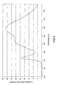
- FIG. 1 A concrete example of the phosphor according to the invention is in FIG. 1 shown.
- This is the emission of the phosphor SrSi 2 N 2 O 2 : (5% Eu 2+ ) in HT modification, in which the Eu content is 5 mol% of the Sr occupied lattice sites.
- the emission maximum is 540 nm, the mean wavelength ⁇ dom at 558 nm.
- the excitation was at 460 nm.
- the FWHM is 76 nm.
- the quantum efficiency is about 90%.
- FIG. 2 shows the diffuse reflection spectrum of this phosphor. It shows a pronounced minimum in the range below 440 nm, which thus demonstrates the good excitability in this area.
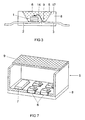
- the construction of a light source for white light is in FIG. 3 shown explicitly.
- the light source is a semiconductor device with a chip 1 of the type InGaN with a peak emission wavelength of 440 to 470 nm, for example 460 nm, which is embedded in an opaque base housing 8 in the region of a recess 9.
- the chip 1 is connected via a bonding wire 14 to a first terminal 3 and directly to a second electrical terminal 2.
- the recess 9 is filled with a casting compound 5, the main constituents of which are an epoxy casting resin (80 to 90% by weight) and phosphor pigments 6 of a mixture of two phosphors (less than 20 wt .-%).
- a first phosphor is the oxinitridosilicate with 5% Eu presented as the first embodiment
- the second is a red emitting phosphor, here in particular (Sr, Ca) 2 Si 5 N 8 : Eu (10%).
- the recess 9 has a wall 17, which serves as a reflector for the primary and secondary radiation from the chip 1 and the pigments 6.
- the combination of the blue primary and green or red secondary radiation mixes to warm white with high Ra of 91 and color temperature of 2850 K.
- the ratio of Sr to Ca in the nitridosilicate is 9: 1.
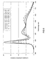
- the associated emission spectrum is in FIG. 5 shown. It shows the intensity in arbitrary units as a function of wavelength (in nm). the peaks of the primary radiation at 460 nm, the oxynitridosilicate at about 560 nm and the nitridosilicate at about 640 nm can be clearly seen.
- the nitridosilicate contains M a Si y N z : Eu as a permanent component Sr and as an admixture Ca in a proportion of 0 to 60 mol%.
- the efficiency and the color rendering index Ra are optimized by the level of doping with Eu, preferably a value for Eu of 5 to 10 mol% of the M.
- the addition of Ca in particular allows too much addition of the dopant Eu avoid.
- LEDs are shown with higher color temperature.
- the total phosphor concentration must be reduced compared to the first embodiment, resulting in a higher transmitted blue LED content and the proportion of green phosphor (oxinitridosilicate) in relation to the red phosphor (nitridosilicate) are increased. It was a LED with 460 nm peak wavelength as the primary light source and blue emitter used.
- the phosphors used here are specifically oxinitridosilicate Sr-SiON: Eu (5%) and nitridosilicate SrCaSiN: Eu (3%).
- the Ra value decreases.
- the Ra drops below 80 at 6500 K color temperature.
- FIG. 7 a lighting system 5 is shown in which in addition to warm white emitting LEDs 6 and the control electronics 7 is housed in a housing 8. 9 is a cover.
Landscapes
- Chemical & Material Sciences (AREA)
- Inorganic Chemistry (AREA)
- Engineering & Computer Science (AREA)
- Materials Engineering (AREA)
- Organic Chemistry (AREA)
- Luminescent Compositions (AREA)
- Led Device Packages (AREA)
Description
- Die Erfindung geht aus von einer LED mit definierter, insbesondere niedriger Farbtemperatur. Darunter wird eine Farbtemperatur im Bereich 2300 bis 7000 K verstanden. Insbesondere handelt es sich um den Bereich 2700 bis 3300 K.
- Der Bereich warmweißer Farbtemperaturen, also unterhalb 3500 K, ist bisher mit kommerziell erhältlichen LEDs schwer zu realisieren. Die gängigen Leuchtstoffe vermitteln eine Farbtemperatur von mehr als 5000 K. Bisher ist daher versucht worden, warmweiße Farbtemperaturen sehr aufwendig durch die Kombination mehrerer LEDs zu erstellen, siehe beispielsweise
WO 02/52901 WO 02/52902 - Aus der
EP 1 296 376 sind bereits Oxinitride verschiedener Stöchiometrie als Leuchtstoffe für die Anwendung bei weißen LED bekannt. Häufig wird dabei als Kation mindestens eines der Metalle Ca,Sr,Ba verwendet. Diese Leuchtstoffe sind vornehmlich für Tageslicht-Anwendungen gedacht. - Einfache LEDs, die sich warmweiße Lichtfarben zum Ziel gesetzt haben, basieren bisher auf UV-Chips. Aufgrund des großen Energieunterschieds zwischen dem UV-Bereich und dem kurzwelligen sichtbaren Bereich (blau) sowie der UV-bedingten , wegen der höheren Energie erhöhten, strahlungsbedingten schnelleren Alterung des Gehäuses und des Leuchtstoffvergusses erreichen diese LEDs weder die Lebensdauer noch die Effizienz von neutralweißen LEDs, wie sie bisher auf Basis von blau emittierenden Chips zur Verfügung stehen.
- Eine Alternative sind RGB-LEDs auf Basis von Lumineszenzkonversions-LEDs mit Sulfid- und Thiogallat-Leuchtstoffen, siehe beispielsweise
WO 01/24229 - Eine andere Lösung, die nachweislich eine hohe Lebensdauer ermöglicht und eine hohe Effizienz bei sehr gutem Farbwiedergabeindex besitzt , ist bisher nicht bekannt. Die Verwendung einer Mischung aus dem bekanten YAG:Ce sowie einem Rot-Leuchtstoff wie beispielsweise Sr2Si5N8:Eu führt nur zu maximalen Ra-Werten von 85 bis 90, siehe dazu
WO 01/40403 - Leuchtstoffe des Typs Oxinitridosilikat sind an sich unter der Kurzformel MSiON bekannt; siehe beispielsweise "On new rare-earth doped M-Si-Al-O-N materials" , J. van Krevel, TU Eindhoven 2000, ISBN 90-386-2711-4, Kap. 6. sie sind mit Tb dotiert. Emission wir erreicht bei Anregung durch 365 nm oder 254 nm.
- Ein neuartiger Leuchtstoff ist aus der noch unveröffentlichten EP-PA 02 021 117.8 (Docket 2002P15736) bekannt. Er besteht aus Eu- oder Eu,Mn-koaktiviertem Oxinitridosilikat der Formel MSi2O2N2 (M = Ca, Sr, Ba).
- Es ist Aufgabe der vorliegenden Erfindung, eine weiße LED mit definierter Lichtfarbe, entsprechend einer Farbtemperatur gemäß dem Oberbegriff des Anspruchs 1 bereitzustellen, deren Ra möglichst hoch ist und mindestens Ra=80 erreicht, insbesondere höher als Ra=85, bevorzugt höher 90.
- Diese Aufgabe wird durch die kennzeichnenden Merkmale des Anspruchs 1 gelöst. Besonders vorteilhafte Ausgestaltungen finden sich in den abhängigen Ansprüchen.
- Bisher gibt es keine zufriedenstellende Realisierung dieser Aufgabenstellung. Es wird nun vorgeschlagen, eine Leuchtstoff-Mischung aus einer speziellen, hocheffizienten grün emittierenden Sr-Sion-Phase sowie einem roten, an sich bekannten Nitrid-Leuchtstoff zu verwenden.
- Die LED ist als weiß emittierende Lumineszenzkonversions-LED ausgeführt, bestehend aus einer Primär-Strahlungsquelle, die ein Chip ist, der im Blauen Spektralbereich emittiert, und einer davor geschalteten Schicht zweier Leuchtstoffe, die die Strahlung des Chip teilweise konvertieren, wobei der erste Leuchtstoff aus der Klasse der Oxinitridosilikate besteht, mit einem Kation M und der grundsätzlichen Formel M(1-c)Si2O2N2:Dc, wobei M als wesentlichen Bestandteil Sr umfasst und wobei D eine Dotierung mit zweiwertigem Europium ist, wobei M = Sr oder M = Sr(1-x-y)BayCax mit 0 ≤ x+y < 0,5 verwendet wird, wobei das Oxinitridosilikat vollständig oder überwiegend aus der hochtemperaturstabilen Modifikation HT besteht, und dass der zweite Leuchtstoff ein Nitridosilikat der Formel (Ca,Sr)2Si5N8:Eu ist, wobei eine Farbtemperatur von 2300 bis 7000 K erzielt wird.
- Erfindungsgemäß wird ein Leuchtstoff verwendet, der ein Oxinitridosilikat der Formel MSi2O2N2 (M = Ca, Sr, Ba) darstellt, das mit zweiwertigem Eu aktiviert ist, unter evtl. weiterer Zugabe von Mn als Koaktivator, wobei der Leuchtstoff überwiegend oder allein, also mit mehr als 50 % des Leuchtstoffs, aus der HT-Phase besteht. Diese HT-Modifikation zeichnet sich dadurch aus, dass sie breitbandig anregbar aus, nämlich in einem weiten Bereich von 200 bis 480 nm, dass sie eine extrem hohe Stabilität gegen äußere Einflüsse besitzt, also bei 150°C keine messbare Degradation zeigt, und dass sie eine extrem gute Farbortstabilität unter wechselnden Bedingungen zeigt (zwischen 20 und 100 °C wenig Drift nachweisbar). Dieser Leuchtstoff wird im folgenden oft Sr-Sion:Eu genannt.
- Dieser Leuchtstoff ist vor allem grün emittierend mit einer Dominanzwellenlänge im Bereich 550 bis 570 nm.
- Bei der Herstellung des neuartigen Leuchtstoffs kommt es vor allem auf eine hohe Temperatur an, der Synthesebereich liegt bei 1300 bis 1600 °C. Ein anderer bestimmender Faktor ist die Reaktivität der Ausgangskomponenten. Diese sollte möglichst hoch sein.
- Insbesondere kann dieser Leuchtstoff von einer LED, vor allem vom Typ InGaN, effizient angeregt werden.
- Der aus
EP-PA 02 021 117.8 - Überraschenderweise hat sich nun gezeigt, dass sich die beiden Phasen in ihrer Eignung als Leuchtstoff grundlegend unterscheiden. Während die NT-Phase als Eudotierter Leuchtstoff praktisch nicht zu gebrauchen ist, und nur schwach orange-rot emittiert, zeigt die HT-Phase eine hervorragende Eignung als Leuchtstoff, der grün emittiert. Im Normalfall liegt eine Mischung vor, die breitbandig beide Emissionen erkennen lässt. Entscheidend ist daher, die HT-Phase möglichst rein, mit mindestens 50 % Anteil, bevorzugt mindestens 70 %, besonders bevorzugt mindestens 85% Anteil herzustellen.
- Dafür ist ein Glühprozess erforderlich, der bei mindestens 1300 °C, aber nicht mehr als 1600 °C durchgeführt wird. Bevorzugt ist ein Temperaturbereich von etwa 1450 bis 1580 °C, da bei geringerer Temperatur zunehmend NT-Phase entsteht und bei höherer Temperatur der Leuchtstoff zunehmend schlechter verarbeitbar ist, und ab etwa 1600 °C als hart gesinterte Keramik oder Schmelze vorliegt. Der optimale Temperaturbereich hängt von der genauen Zusammensetzung und den Eigenschaften der Ausgangsmaterialien ab.
- Besonders wichtig für das Herstellen eines effizienten Leuchtstoffs des Typs Sr-Sion ist ein Ansatz der Ausgangsprodukte, der im wesentlichen stöchiometrisch ist unter Verwendung der Grundkomponenten SiO 2, SrCO 3 sowie Si 3 N 4. Sr steht hier beispielhaft stellvertretend für M. Die Abweichung sollte insbesondere 10 %, bevorzugt 5 %, des idealen stöchiometrischen Ansatzes nicht überschreiten, wobei auch die etwaige Zugabe eines Schmelzmittels, wie es oft üblich ist, dabei eingeschlossen ist. Besonders bevorzugt ist eine maximale Abweichung von 1 %. Hinzu kommt ein Vorläufer für den Europium-Beitrag der Dotierung, der beispielsweise als Oxid Eu 2 O 3 realisiert wird. Diese Erkenntnis steht im Gegensatz zu der bisherigen Vorgehensweise, die Grundkomponente SiO 2 deutlich unterstöchiometrisch zuzugeben. Besonders überraschend ist diese Erkenntnis auch deswegen, weil andere als Leuchtstoff empfohlene Sione wie Ba-Sion gemäß der Lehre von EP-PA 02 021 117.8 gerade im SiO2-Unterschuss hergestellt werden sollen.
- Ein entsprechender Ansatz für das Sr-Sion MSi2O2N2 verwendet daher 11 bis 13 Gew.-% SiO 2 , 27 bis 29 Gew.-% Si 3 N 4 , Rest SrCO 3. Ba- und Ca- Anteile an M werden entsprechend als Carbonat zugesetzt. Europium wird entsprechend der gewünschten Dotierung, beispielsweise als Oxid oder Fluorid, als Ersatz für SrCO 3 zugesetzt. Der Ansatz MSi2O2N2 meint dabei auch etwaige Abweichungen von der exakten Stöchiometrie, soweit sie hinsichtlich der Ladungserhaltung ausgeglichen sind.
- Als besonders günstig hat sich erwiesen, dass die Ausgangskomponenten des Wirtsgitters, insbesondere Si 3 N 4 , möglichst hohe Reinheit besitzen. Besonders bevorzugt ist daher Si 3 N 4 , das aus der flüssigen Phase, ausgehend beispielsweise von Siliziumtetrachlorid, synthetisiert ist. Als kritisch hat sich insbesondere die Verunreinigung mit Wolfram und Kobalt, erwiesen. Hier sollte die Verunreinigung möglichst gering sein, insbesondere sollte sie jeweils kleiner 100 ppm, insbesondere kleiner 50 ppm, sein, bezogen auf diese Vorläufersubstanzen. Des weiteren ist eine möglichst hohe Reaktivität vorteilhaft, sie lässt sich durch die reaktive Oberfläche (BET) quantifizieren. Diese sollte mindestens 6 m2/g betragen, vorteilhaft mindestens 8 m2/g. Auch die Verunreinigung an Aluminium und Calcium, bezogen auf diese Vorläufersubstanz Si 3 N 4, sollte möglichst unter 100 ppm liegen.
- Bei Abweichung von der oben angegebenen Verfahrensführung in bezug auf stöchiometrischen Ansatz und Temperaturführung entstehen als unerwünschte Fremdphasen in zunehmendem Maße Nitridosilikate MxSiyNz wie etwa M2Si5N8, wenn die SiO2-Zugabe zu niedrig angesetzt wird, so dass ein Stickstoffüberschuss entsteht. Obwohl diese Verbindung an sich ein bemerkenswerter Leuchtstoff ist, ist sie in Zusammenhang mit der Synthese des Sr-Sions genauso wie andere Nitridosilikate äußerst störend, weil diese Fremdphasen die grüne Strahlung des Sr-Sions absorbieren und evtl. in die bekannte rote Strahlung der Nitridosilikate umwandeln. Umgekehrt entstehen bei zu hoher SiO2-Zugabe Sr-Silikate wie beispielsweise Sr2SiO4 weil ein Sauerstoffüberschuss entsteht. Beide Fremdphasen absorbieren die nutzbare grüne Emission oder führen zumindest zu Gitterdefekten wie Leerstellen, die die Effizienz des Leuchtstoffs stark beeinträchtigen. Als Anhaltspunkt dient die Richtschnur, dass der Anteil der Fremdphasen möglichst unter 15 %, bevorzugt sogar unter 5 %, liegen soll. Dies korrespondiert im XRD-Spektrum des synthetisierten Leuchtstoffs mit der Forderung, dass beim XRD-Ablenkwinkei 2 Θ im Bereich 25 bis 32° die Intensität aller Fremdphasenpeaks kleiner als 1/3, bevorzugt kleiner als % , besonders bevorzugt kleiner als 1/5, der Intensität des die HT-Modifikation kennzeichnenden Hauptpeaks bei etwa 31,8° sein soll. Dies gilt vor allem für die Fremdphasen vom Typ SrxSiyNz, insbesondere Sr2Si5N8.
- Im Falle einer optimierten Verfahrensführung lässt sich zuverlässig eine Quanteneffizienz von 80 bis deutlich über 90 % erzielen. Dagegen wird bei unspezifischer Verfahrensführung die Effizienz typisch im Bereich von höchstens 50 bis 60 % Quanteneffizienz liegen.
- Es lässt sich somit ein Leuchtstoff herstellen, der ein Oxinitridosilikat der Formel MSi2O2N2 (M = Ca, Sr, Ba) darstellt, das mit zweiwertigem Eu aktiviert ist, unter evtl. weiterer Zugabe von Mn als Koaktivator, wobei der Leuchtstoff überwiegend oder allein, also mit mehr als 50 % des Leuchtstoffs, aus der HT-Phase besteht. Diese HT-Modifikation zeichnet sich dadurch aus, dass er breitbandig anregbar ist, insbesondere in einem weiten Bereich von 250 bis 480 nm, dass er eine extrem hohe Stabilität gegen äußere Einflüsse besitzt, also bei 150°C an Luft keine messbare Degradation zeigt, dass er eine extrem gute Farbortstabilität unter wechselnden Bedingungen zeigt. Weitere Pluspunkte sind seine geringe Absorption im Roten, was besonders bei Leuchtstoffmischungen vorteilhaft ist. Dieser Leuchtstoff wird im folgenden oft Sr-Sion:Eu genannt. Ein Überwiegen der HT-Modifikation ist u.a. daran erkennbar, dass der kennzeichnende Peak der NT-Modifikation im XRD-Spektrum bei etwa 28,2 ° eine Intensität von weniger als 1:1, bevorzugt weniger als 1:2, im Vergleich zum Peak mit höchster Intensität aus der Dreiergruppe der Reflexe der HT-Modifikation, die im XRD-Spektrum bei 25 bis 27° liegen, aufweist. Die hier aufgeführten XRD-Spektren beziehen sich jeweils auf eine Anregung durch die bekannte Cu-Kα Linie.
- Bei gleicher Aktivatorkonzentration zeigt dieser Leuchtstoff ein anderes Emissionsverhalten als die NT-Variante gleicher Stöchiometrie. Die Halbwertsbreite der HT-Variante ist im Falle der optimierten HT-Variante wesentlich geringer als bei der einfachen fremdphasen- und defekthaltigen Mischung und liegt im Bereich 70 bis 80 nm, während die einfache Fremdphasen- bzw. defekthaltige Mischung eine Halbwertsbreite von etwa 110 bis 120 nm zeigt. Die dominante Wellenlänge ist bei der HT-Modifikation generell kürzer, typisch 10 bis 20 nm kürzer, als bei einer deutlich fremdphasenhaltigen Probe. Hinzu kommt, dass die Effizienz der hochreinen HT Modifikation typisch um mindestens 20 % höher, teilweise deutlich noch höher, als bei der NT-dominierten oder hoch fremdphasenhaltigen Mischung liegt.
- Ein Merkmal eines ausreichend geringen Anteils der NT-Modifikation und Fremdphasen ist eine Halbwertsbreite (FWHM) der Emission von weniger als 90 nm. Denn je geringer der Anteil an Fremdphasen, desto geringer ist der Anteil der spezifischen orange-roten Emission der fremdphasenreichen Modifikation, insbesondere der Nitridosilikat-Fremdphasen Sr-Si-N-Eu wie vor allem Sr2Si5N8:Eu.
- Hilfreich sind neben der verringerten Halbwertsbreite die oben angegebenen typischen Reflexe im XRD-Spekrum, die die andere Kristallstruktur verdeutlichen.
- Der vorherrschende Peak im XRD-Spektrum der HT-Modifikation ist der Peak bei etwa 31.7°. Weitere prominente Peaks sind die drei Peaks etwa gleicher Intensität zwischen 25 und 27° (25,3 und 26,0 und 26,3°), wobei der Peak mit kleinster Ablenkung der intensivste ist. Ein weiterer intensiver Peak ist 12,6°.
- Dieser Leuchtstoff ist vor allem grün emittierend mit einer Dominanzwellenlänge im Bereich 550 bis 570 nm, insbesondere 555 bis 565 nm.
- Auch eine geringfügige Beimengung der Gruppe AIO als Ersatz der Gruppe SiN im Molekül des Oxinitridosilikats der Formel MSi2O2N2 ist möglich, insbesondere bis maximal 30 % des SiN-Anteils.
- Beide Phasen des Sr-Sion:Eu können analog zu den zwei strukturell unterschiedlichen Wirtsgittermodifikationen kristallisieren und jeweils über die Ansatzstöchiometrie SrSi2O2N2:Eu hergestellt werden. Geringe Abweichungen von dieser Stöchiometrie sind möglich. Die mit Eu dotierten Wirtsgitter lumineszieren überraschenderweise beide bei Anregung im Blauen oder UV, allerdings je nach Wirtsgittermodifikation mit anderer Emissionsfarbe. Die NT-Modifikation zeigt eine orangefarbene Emission, die HT-Modifikation eine grüne Emission bei etwa λdom = 560 nm mit prinzipiell deutlich höherer Effizienz. Je nach Dotiergehalt und Dotiermaterial (Eu oder Eu, Mn) sowie den relativen Anteilen der HT- und NT-Modifikation +lässt sich eine gewünschte Eigenschaft des Leuchtstoffs genau einstellen.
- Ein Vorzug der HT-Phase ist die über einen sehr weiten Spektralbereich gleichmä-βig gute Anregbarkeit bei nur wenig variierender Quanteneffizienz.
- Außerdem hängt die Lumineszenz der HT-Modifikation in einem weiten Temperaturbereich nur schwach von der Temperatur ab. Damit ist erstmals ein grün emittierender Leuchtstoff, bevorzugt für LED-Anwendungen, gefunden, der ohne besondere Maßnahmen zur Stabilisierung auskommt. Dies zeichnet ihn besonders gegen die bisher als aussichtsreichste Kandidaten angesehenen Leuchtstoffe für diese Aufgabe aus, nämlich Thiogallat-Leuchtstoffe oder Chlorosilikate.
- Die Sionverbindungen mit M = (Sr,Ba), bevorzugt ohne Ba oder mit Ba-Anteil bis zu 10 %, stellen effiziente Leuchtstoffe mit einem weiten Bereich der Emissionsmaxima dar. Diese liegen meist kurzwelliger als bei reinem Sr-Sion, bevorzugt zwischen 520 und 565 nm. Der erreichbare Farbraum lässt sich außerdem durch geringe Beigaben (bevorzugt bis 30 mol-%) an Ca und/oder Zink erweitern; dadurch werden die Emissionsmaxima eher in den langwelligeren Bereich, verglichen mit reinem Sr-Sion, verschoben, sowie durch partiellen Ersatz (bis 25 mol-%) von Si durch Ge und/oder Sn.
- Eine weitere Ausführungsform ist die Teilsubstitution von M, insbesondere Sr, durch drei- oder einwertige Ionen wie La3+ oder Li+ oder Na+ oder Y3+. Bevorzugt ist ein Anteil dieser Ionen von maximal 20 mol-% des M.
- Überraschend ist nun mit dem Sr-Sion der HT-Phase ein Leuchtstoff gefunden, der sich exakt auf eine grüne Peakemission, beispielsweise der Wellenlänge 560 nm (Dominanzwellenlänge), einstellen lässt. Der Leuchtstoff wandelt das Licht einer blauen oder UV-LED mit einer Quanteneffizienz von deutlich mehr als 80 % um. Die lumenbewertete Effizienz ist vergleichbar mit der typischer weißer LEDs auf YAG:Ce-Basis.
- Als weiterer Vorteil ist anzusehen, daß die Emissionsfarbe der Lumineszenzkonversions-LED praktisch unabhängig von der Betriebstemperatur ist, damit kann die LED gut bei unterschiedlichen Außentemperaturen betriebe werden und ist farbortstabil dimmbar.
- Die zweite Leuchtstoff-Komponente ist das eingangs erwähnte Nitrid des Typs (Sr,Ca)2Si5N8:Eu in geeigneter Zusammensetzung. Mit diesen beiden Leuchtstoffen, deren typische Quanteneffizienzen deutlich über 80 % liegen, und die beide sehr gut im Bereich kurzwelliger blauer Strahlung absorbieren, vor allem auch bei 450 bis 465 nm, wo die stärksten Chips zur Verfügung stehen, lassen sich effiziente warmweiße LEDs mit einem Farbwiedergabeindex Ra von bis zu 95 bereitstellen. Ein typischer Ra-Wert liegt je nach gewünschter Optimierung bei 85 bis 95.
- Der besondere Vorteil gerade dieser Kombination ist, dass beide Leuchtstoffe ein ähnliches Temperaturverhalten zeigen, was die Effizienz der Lumineszenz betrifft, wodurch vorteilhaft dimmbare LEDs bei möglichst konstantem Farbort ermöglicht werden.
- Die Temperaturabhängigkeit der Lumineszenz ist signifikant geringer als bei den bisher vorgeschlagenen sulfidischen Leuchtstoffen, beide Arten von Leuchtstoffen außerdem chemisch deutlich stabiler als ihre bisher bekannten sulfidischen Alternativen (SrS:Eu und Thiogallate). Die beiden Nitrid-basierten Leuchtstoffe und ihre möglichen Zersetzungsprodukte sind weitgehend ungiftig, was beim Aspekt der Umweltschonung eine Rolle spielt.
- Für den Einsatz in der LED können Standardverfahren eingesetzt werden. Insbesondere ergeben sich folgende Realisierungsmöglichkeiten.
- Erstens das Eindispergieren des Leuchtstoff in den LED-Verguss, beispielsweise ein Silikon oder Epoxidharz, und anschließendes Aufbringen durch beispielsweise Vergießen, Drucken, Spritzen o.ä. Zweitens Einbringen des Leuchtstoffs in eine sog. Pressmasse und anschließendes Spritzpressverfahren. Drittens Methoden der chipnahen Konversion, d.h. Aufbringen der Leuchtstoffe bzw. deren Mischung auf der Wafer-Prozessings-Ebene, nach dem Vereinzeln der Chips und nach der Montage im LED-Gehäuse. Hierzu wird insbesondere auf
DE 101 53 615 undWO 01/50540 - Die Erfindung betrifft weiterhin ein Beleuchtungssystem mit LEDs wie oben beschrieben, wobei das Beleuchtungssystem weiterhin elektronische Komponenten enthält. diese vermitteln beispielsweise die Dimmbarkeit. Eine weitere Aufgabe der Elektronik ist die Ansteuerung einzelner LEDs oder auch Gruppen von LEDs diese Funktionen können durch vorbekannte elektronische Elemente realisiert sein.
- Im folgenden soll die Erfindung anhand zweier Ausführungsbeispiele näher erläutert werden. Es zeigen:
- Figur 1
- ein Emissionsspektrum eines Oxinitridosilikats;
- Figur 2
- das Reflektionsspektrum dieses Oxinitridosilikats;
- Figur 3
- ein Halbleiterbauelement, das als Lichtquelle für warmweißes Licht dient;
- Figur 4
- die Lage des Farborts verschiedener Chargen einer warmweißen LED;
- Figur 5
- ein Emissionsspektrum einer Lichtquelle gemäß
Figur 3 ; - Figur 6
- weitere Emissionsspektren von Lichtquellen gemäß
Figur 3 ; - Figur 7
- ein Beleuchtungssystem auf Basis warmweißer LEDs.
- Ein konkretes Beispiel für den erfindungsgemäßen Leuchtstoff ist in
Figur 1 gezeigt. Es handelt sich um die Emission des Leuchtstoffs SrSi2N2O2:(5 % Eu2+) in HT-Modifikation, bei dem der Eu-Anteil 5 mol-% der von Sr besetzten Gitterplätze ausmacht. Das Emissionsmaximum liegt bei 540 nm, die mittlere Wellenlänge λdom bei 558 nm. Der Farbort ist x=0,357; y=0,605. Die Anregung erfolgte bei 460 nm. die FWHM ist 76 nm. Die Quanteneffizienz liegt bei etwa 90 %. Der Farbort ist x = 0,357, y = 0,605. -
Figur 2 zeigt das diffuse Reflexionsspektrum dieses Leuchtstoffs. Es zeigt ein ausgeprägtes Minimum im Bereich unter 440 nm, das somit die gute Anregbarkeit in diesem Bereich demonstriert. - Der Aufbau einer Lichtquelle für weißes Licht ist in
Figur 3 explizit gezeigt. Die Lichtquelle ist ein Halbleiterbauelement mit einem Chip 1 des Typs InGaN mit einer Peakemissionswellenlänge von 440 bis 470 nm, beispielsweise 460 nm, das in ein lichtundurchlässiges Grundgehäuse 8 im Bereich einer Ausnehmung 9 eingebettet ist. Der Chip 1 ist über einen Bonddraht 14 mit einem ersten Anschluss 3 und direkt mit einem zweiten elektrischen Anschluss 2 verbunden. Die Ausnehmung 9 ist mit einer Vergussmasse 5 gefüllt, die als Hauptbestandteile ein Epoxidgießharz (80 bis 90 Gew.-%) und Leuchtstoffpigmente 6 aus einer Mischung zweier Leuchtstoffe (weniger als 20 Gew.-%) enthält. Ein erster Leuchtstoff ist das als erstes Ausführungsbeispiel vorgestellte Oxinitridosilikat mit 5 %Eu, der zweite ist ein rot emittierender Leuchtstoff, hier insbesondere (Sr,Ca)2Si5N8:Eu(10%). Die Ausnehmung 9 hat eine Wand 17, die als Reflektor für die Primär- und Sekundärstrahlung vom Chip 1 bzw. den Pigmenten 6 dient. Die Kombination der blauen Primär- und grünen bzw. roten Sekundärstrahlung mischt sich zu warmweiß mit hohem Ra von 91 und Farbtemperatur von 2850 K. Der angestrebte Farbort liegt im Bereich x = 0,44 bis 0,48 sowie y = 0,40 bis 0,44, sieheFigur 4 . Das Verhältnis Sr zu Ca beim Nitridosilikats ist hier 9:1. - Das zugehörige Emissionsspektrum ist in
Figur 5 gezeigt. Es zeigt die Intensität in willkürlichen Einheiten als Funktion der Wellenlänge (in nm). deutlich sind die Peaks der Primärstrahlung bei 460 nm, des Oxinitridosilikats bei etwa 560 nm und des Nitridosilikats bei etwa 640 nm zu erkennen. - Generell enthält das Nitridosilikat MaSiyNz:Eu als permanente Komponente Sr und als Beimischung Ca in einem Anteil von 0 bis 60 mol-%. Insbesondere ist das bevorzugte Nitridosilikat durch die Formel (Sr1-xCax)2SiyNz mit x = 0 bis 0,6 charakterisiert, wobei hier y = 5 und z = 8 und generell y,z ≤ 10 gewählt wird. Im allgemeinen wird die Effizienz und der Farbwiedergabeindex Ra durch die Höhe der Dotierung mit Eu optimiert, bevorzugt ist ein Wert für Eu von 5 bis 10 mol-% des M. Die Zugabe von Ca gestattet es insbesondere, eine allzu hohe Zugabe des Dotiermittels Eu zu vermeiden. Es hat sich gezeigt, dass zur Erzielung hoher Farbwiedergabeindices eine Zugabe von Ca und eine Begrenzung des Eu-Anteils empfehlenswert ist. Für Ra > 90 kann daher x bis maximal 0,2 (bevorzugt x bis 0,1) gewählt werden, und gleichzeitig Eu bevorzugt im Bereich 3 bis 15 mol-% von M (bevorzugt 5 bis 10 mol-%) angesetzt werden. Gute Ergebnisse mit hohem Ra lassen sich auch für 0,2 < x < 0,55 erzielen, wenn gleichzeitig Eu auf 1 bis 5 mol-% von M gesetzt wird.
- In
Figur 6 sind LEDs mit höherer Farbtemperatur gezeigt. Zur Erzielung höherer Farbtemperaturen als etwa 3300 K muss die Gesamtleuchtstoffkonzentration im Vergleich zum ersten Ausführungsbeispiel reduziert werden, wodurch ein höherer transmittierter Blau-LED-Anteil resultiert sowie der Anteil des Grünleuchtstoffs (Oxinitridosilikat) im Verhältnis zum Rotleuchtstoff (Nitridosilikat) erhöht werden. Es wurde eine LED mit 460 nm Peakwellenlänge als Primärlichtquelle und blauer Emitter verwendet. Eingesetzte Leuchtstoffe sind hier konkret als Oxinitridosilikat Sr-SiON:Eu(5%) und als Nitridosilikat SrCaSiN:Eu(3%). - Bei Verwendung einer kürzerwelligen LED sinkt der Ra-Wert. Beispielsweise zeigt sich, dass bei Verwendung einer primären LED mit 450 nm Peakwellenlänge der Ra unter 80 bei 6500 K Farbtemperatur sinkt.
- In
Figur 7 ist ein Beleuchtungssystem 5 gezeigt, bei dem neben warmweiß emittierenden LEDs 6 auch die Steuerelektronik 7 in einem Gehäuse 8 untergebracht ist. mit 9 ist eine Abdeckung bezeichnet.
Claims (15)
- Weiß emittierende LED mit definierter Farbtemperatur, als Lumineszenzkonversions-LED ausgeführt, bestehend aus einer Primär-Strahlungsquelle, die ein Chip ist, der im blauen Spektralbereich emittiert, und einer davor geschalteten Schicht zweier Leuchtstoffe, die beide die Strahlung des Chips teilweise konvertieren, dadurch gekennzeichnet, dass der erste Leuchtstoff aus der Klasse der Oxinitridosilikate besteht, mit einem Kation M und der grundsätzlichen Formel M(1-c)Si2O2N2:Dc, wobei M als wesentlichen Bestandteil Sr allein oder in Kombination mit Ba und/oder Ca umfasst, und wobei D eine Dotierung mit zweiwertigem Europium ist, wobei M = Sr oder M = Sr(1-x-y)BayCax mit 0 ≤ x+y < 0,5 verwendet wird, und wobei weiterhin ein Teil von M durch Li und/oder La und/oder Na und/oder Y und/oder Zn gebildet sein kann, und wobei weiterhin ein Teil von SiN durch AlO ersetzt sein kann, und wobei weiterhin ein Teil von D durch Mn gebildet sein kann, und wobei das Oxinitridosilikat vollständig oder überwiegend aus der hochtemperaturstabilen Modifikation HT besteht, und dass der zweite Leuchtstoff ein Nitridosilikat der Formel (Ca,Sr)2Si5N8:Eu ist, wobei eine Farbtemperatur von 2300 bis 7000 K erzielt wird und gleichzeitig eine Farbwiedergabe von wenigstens Ra = 80 erzielt wird.
- LED nach Anspruch 1, dadurch gekennzeichnet, dass der Anteil des Eu beim Oxinitridosilikat zwischen 0,1 und 20 mol-% von M ausmacht.
- LED nach Anspruch 1, dadurch gekennzeichnet, dass bis zu 30 mol-% von M durch Ba und/oder Ca und/oder Zn gebildet ist.
- LED nach Anspruch 1, dadurch gekennzeichnet, dass bis zu 30 mol-% von M durch Li und/oder La und/oder Na und/oder Y gebildet ist.
- LED nach Anspruch 1, dadurch gekennzeichnet, dass bis zu 30 mol-% von SiN durch AlO ersetzt ist.
- LED nach Anspruch 1, dadurch gekennzeichnet, dass bis zu 30 mol-% von Eu durch Mn ersetzt ist.
- LED nach Anspruch 1, dadurch gekennzeichnet, dass der Chip ein InGaN-Chip ist.
- LED nach Anspruch 1, dadurch gekennzeichnet, dass die LED die weiße Lichtfarbe durch Farbmischung nach dem RGB-Prinzip erzielt, wobei die Primäremission der blauen LED eine Peakwellenlänge von 430 bis 470 nm besitzt..
- LED nach Anspruch 8, dadurch gekennzeichnet, dass die Emission des Chips eine Peakwellenlänge im Bereich 450 bis 465 nm hat.
- LED nach Anspruch 1, dadurch gekennzeichnet, dass die Emission des Oxinitridosilikats eine dominante Wellenlänge λdom im Bereich 550 bis 570 nm hat.
- LED nach Anspruch 1, dadurch gekennzeichnet, dass das Nitridosilikat Sr als permanente Komponente und Ca in einem Anteil von 0 bis 60 mol-% enthält.
- LED nach Anspruch 1, dadurch gekennzeichnet, dass die Emission des Nitridosilikats eine dominante Wellenlänge λdom im Bereich 620 bis 660 nm hat.
- LED nach Anspruch 1, dadurch gekennzeichnet, dass ein Ra von mindestens 85 erzielt wird.
- Beleuchtungssystem mit einer LED nach Anspruch 1, dadurch gekennzeichnet, dass das System eine Elektronik zur Ansteuerung einzelner LEDs oder auch Gruppen von LEDs enthält.
- Beleuchtungssystem nach Anspruch 14, wobei die elektronische Steuerung Mittel enthält, die Dimmbarkeit vermitteln.
Applications Claiming Priority (2)
| Application Number | Priority Date | Filing Date | Title |
|---|---|---|---|
| DE10344331 | 2003-09-24 | ||
| PCT/DE2004/002138 WO2005031797A2 (de) | 2003-09-24 | 2004-09-24 | Weiss emittierende led mit definierter farbtemperatur |
Publications (2)
| Publication Number | Publication Date |
|---|---|
| EP1664239A2 EP1664239A2 (de) | 2006-06-07 |
| EP1664239B1 true EP1664239B1 (de) | 2013-01-30 |
Family
ID=34384254
Family Applications (1)
| Application Number | Title | Priority Date | Filing Date |
|---|---|---|---|
| EP04786854A Expired - Lifetime EP1664239B1 (de) | 2003-09-24 | 2004-09-24 | Weiss emittierende led mit definierter farbtemperatur |
Country Status (7)
| Country | Link |
|---|---|
| US (1) | US7965031B2 (de) |
| EP (1) | EP1664239B1 (de) |
| JP (1) | JP4805829B2 (de) |
| KR (1) | KR101117365B1 (de) |
| CN (1) | CN1886484B (de) |
| TW (1) | TWI344220B (de) |
| WO (1) | WO2005031797A2 (de) |
Families Citing this family (41)
| Publication number | Priority date | Publication date | Assignee | Title |
|---|---|---|---|---|
| TW200523340A (en) * | 2003-09-24 | 2005-07-16 | Patent Treuhand Ges Fur Elek Sche Gluhlampen Mbh | Hochefeizienter leuchtstoff |
| ATE395391T1 (de) | 2004-05-27 | 2008-05-15 | Koninkl Philips Electronics Nv | Beleuchtungssystem mit einer strahlungsquelle und einem fluoreszierenden material |
| DE102004051395A1 (de) * | 2004-10-21 | 2006-04-27 | Patent-Treuhand-Gesellschaft für elektrische Glühlampen mbH | Hocheffizienter stabiler Oxinitrid-Leuchtstoff |
| US7821023B2 (en) | 2005-01-10 | 2010-10-26 | Cree, Inc. | Solid state lighting component |
| US9793247B2 (en) * | 2005-01-10 | 2017-10-17 | Cree, Inc. | Solid state lighting component |
| US9070850B2 (en) | 2007-10-31 | 2015-06-30 | Cree, Inc. | Light emitting diode package and method for fabricating same |
| US8269410B2 (en) | 2005-03-18 | 2012-09-18 | Mitsubishi Chemical Corporation | Light-emitting device, white light-emitting device, illuminator, and image display |
| US7489073B2 (en) * | 2005-04-15 | 2009-02-10 | Patent-Treuhand-Gesellschaft für elektrische Glühlampen mbH | Blue to yellow-orange emitting phosphor, and light source having such a phosphor |
| JP5098221B2 (ja) * | 2005-05-24 | 2012-12-12 | 三菱化学株式会社 | 発光装置、照明装置、ディスプレイ用バックライトおよびディスプレイ |
| DE102005059521A1 (de) | 2005-12-13 | 2007-06-14 | Patent-Treuhand-Gesellschaft für elektrische Glühlampen mbH | Rot emittierender Leuchtstoff und Lichtquelle mit einem derartigen Leuchtstoff |
| DE102006008300A1 (de) | 2006-02-22 | 2007-08-30 | Patent-Treuhand-Gesellschaft für elektrische Glühlampen mbH | Leuchtstoff und Lichtquelle mit derartigem Leuchtstoff sowie Herstellverfahren für den Leuchtstoff |
| US9335006B2 (en) | 2006-04-18 | 2016-05-10 | Cree, Inc. | Saturated yellow phosphor converted LED and blue converted red LED |
| US10295147B2 (en) | 2006-11-09 | 2019-05-21 | Cree, Inc. | LED array and method for fabricating same |
| KR20080049947A (ko) * | 2006-12-01 | 2008-06-05 | 엘지전자 주식회사 | 방송 시스템, 인터페이스 방법, 및 데이터 구조 |
| JP2008283155A (ja) * | 2007-05-14 | 2008-11-20 | Sharp Corp | 発光装置、照明機器および液晶表示装置 |
| EP2212400B9 (de) * | 2007-10-15 | 2014-04-16 | Leuchtstoffwerk Breitungen GmbH | Se-dotierter erdalkalisiliciumnitridleuchtstoff, verfahren zur herstellung und einen derartigen leuchtstoff umfassende strahlungskonvertierungsvorrichtung |
| KR101245005B1 (ko) * | 2008-02-18 | 2013-03-18 | 가부시키가이샤 고이토 세이사꾸쇼 | 백색 발광 장치 및 이것을 이용한 차량용 등기구 |
| WO2009117148A2 (en) * | 2008-03-21 | 2009-09-24 | Nanogram Corporation | Metal silicon nitride or metal silicon oxynitride submicron phosphor particles and methods for synthesizing these phosphors |
| CN101677117B (zh) * | 2008-09-19 | 2012-03-21 | 展晶科技(深圳)有限公司 | 高演色性发光二极管的配置方法与系统 |
| US9425172B2 (en) | 2008-10-24 | 2016-08-23 | Cree, Inc. | Light emitter array |
| DE102008058295A1 (de) * | 2008-11-20 | 2010-05-27 | Osram Gesellschaft mit beschränkter Haftung | Rot emittierender Leuchtstoff aus der Klasse der Nitridosilikate und Lichtquelle mit derartigem Leuchtstoff sowie Verfahren zur Herstellung des Leuchtstoffs |
| US8598809B2 (en) | 2009-08-19 | 2013-12-03 | Cree, Inc. | White light color changing solid state lighting and methods |
| WO2011044974A1 (de) | 2009-10-13 | 2011-04-21 | Merck Patent Gmbh | Leuchtstoffmischungen mit europium dotieren ortho-silikaten |
| US8511851B2 (en) | 2009-12-21 | 2013-08-20 | Cree, Inc. | High CRI adjustable color temperature lighting devices |
| CN101775292A (zh) * | 2010-02-23 | 2010-07-14 | 厦门大学 | 一种Eu掺杂氮氧化物荧光粉的制备方法 |
| CN102344797A (zh) * | 2010-07-29 | 2012-02-08 | 福华电子股份有限公司 | 一种荧光粉组成物及使用该荧光粉的交流电发光二极管 |
| KR101225002B1 (ko) * | 2010-09-27 | 2013-01-22 | 삼성전자주식회사 | 형광체 및 이의 제조방법 |
| KR101196845B1 (ko) * | 2010-10-11 | 2012-11-01 | 한국화학연구원 | (할로)금속실리콘산질화물 형광체 및 이의 제조방법 |
| US9786811B2 (en) | 2011-02-04 | 2017-10-10 | Cree, Inc. | Tilted emission LED array |
| US10842016B2 (en) | 2011-07-06 | 2020-11-17 | Cree, Inc. | Compact optically efficient solid state light source with integrated thermal management |
| USD700584S1 (en) | 2011-07-06 | 2014-03-04 | Cree, Inc. | LED component |
| WO2013129854A1 (ko) | 2012-02-27 | 2013-09-06 | 경기대학교 산학협력단 | 실리콘 산질화물 형광체, 이의 제조 방법 및 이를 포함하는 광소자 |
| KR101409489B1 (ko) | 2012-02-27 | 2014-06-18 | 경기대학교 산학협력단 | 실리콘 산질화물 형광체 및 이를 포함하는 광소자 |
| KR101449639B1 (ko) | 2013-02-27 | 2014-10-13 | 경기대학교 산학협력단 | 실리콘 산질화물 형광체, 이의 제조 방법 및 이를 포함하는 광소자 |
| KR101970774B1 (ko) * | 2012-07-17 | 2019-04-19 | 엘지이노텍 주식회사 | 형광체 및 발광 장치 |
| US9612002B2 (en) | 2012-10-18 | 2017-04-04 | GE Lighting Solutions, LLC | LED lamp with Nd-glass bulb |
| US9370072B2 (en) | 2013-02-28 | 2016-06-14 | Vilnius University | Solid-state sources of light for preferential colour rendition |
| CN104371710A (zh) * | 2014-11-14 | 2015-02-25 | 广东华科新材料研究院有限公司 | 一种新型绿色氮硅氧荧光粉及其制备方法 |
| KR102235612B1 (ko) | 2015-01-29 | 2021-04-02 | 삼성전자주식회사 | 일-함수 금속을 갖는 반도체 소자 및 그 형성 방법 |
| CN105047770B (zh) * | 2015-07-08 | 2018-01-16 | 东南大学 | 一种快速制备白光led器件的方法 |
| US11578841B2 (en) | 2019-04-17 | 2023-02-14 | Biological Innovation And Optimization Systems, Llc | Color separation lighting devices |
Family Cites Families (37)
| Publication number | Priority date | Publication date | Assignee | Title |
|---|---|---|---|---|
| US4897319A (en) * | 1988-07-19 | 1990-01-30 | Planar Systems, Inc. | TFEL device having multiple layer insulators |
| DE59308636D1 (de) | 1992-08-28 | 1998-07-09 | Siemens Ag | Leuchtdiode |
| JPH11510968A (ja) | 1996-06-11 | 1999-09-21 | フィリップス エレクトロニクス ネムローゼ フェンノートシャップ | 紫外発光ダイオード及び紫外励起可視光放射蛍光体を含む可視発光ディスプレイ及び該デバイスの製造方法 |
| JP3356041B2 (ja) | 1997-02-17 | 2002-12-09 | 昭和電工株式会社 | リン化ガリウム緑色発光素子 |
| US6255670B1 (en) * | 1998-02-06 | 2001-07-03 | General Electric Company | Phosphors for light generation from light emitting semiconductors |
| US6158882A (en) * | 1998-06-30 | 2000-12-12 | Emteq, Inc. | LED semiconductor lighting system |
| TW417842U (en) | 1998-09-28 | 2001-01-01 | Koninkl Philips Electronics Nv | Lighting system |
| US6495964B1 (en) | 1998-12-18 | 2002-12-17 | Koninklijke Philips Electronics N.V. | LED luminaire with electrically adjusted color balance using photodetector |
| US6686691B1 (en) | 1999-09-27 | 2004-02-03 | Lumileds Lighting, U.S., Llc | Tri-color, white light LED lamps |
| EP1142033A1 (de) * | 1999-09-27 | 2001-10-10 | LumiLeds Lighting U.S., LLC | Weisslicht emittierende diodenvorrichtung mittels vollständiger phosphor-umwandlung |
| EP1104799A1 (de) | 1999-11-30 | 2001-06-06 | Patent-Treuhand-Gesellschaft für elektrische Glühlampen mbH | Rotstrahlendes lumineszentes Material |
| US6513949B1 (en) | 1999-12-02 | 2003-02-04 | Koninklijke Philips Electronics N.V. | LED/phosphor-LED hybrid lighting systems |
| DE19963806C2 (de) * | 1999-12-30 | 2002-02-07 | Osram Opto Semiconductors Gmbh | Verfahren zum Herstellen einer Leuchtdioden-Weißlichtquelle, Verwendung einer Kunststoff-Preßmasse zum Herstellen einer Leuchtioden-Weißlichtquelle und oberflächenmontierbare Leuchtdioden-Weißlichtquelle |
| DE60030541T2 (de) * | 2000-01-06 | 2007-08-30 | Koninklijke Philips Electronics N.V. | Leuchte und leuchttafeln |
| US6603258B1 (en) | 2000-04-24 | 2003-08-05 | Lumileds Lighting, U.S. Llc | Light emitting diode device that emits white light |
| US6621211B1 (en) | 2000-05-15 | 2003-09-16 | General Electric Company | White light emitting phosphor blends for LED devices |
| DE10024924A1 (de) | 2000-05-19 | 2001-11-29 | Osram Opto Semiconductors Gmbh | Licht emittierendes Halbleiterbauelement |
| JP2004505172A (ja) * | 2000-07-28 | 2004-02-19 | オスラム オプト セミコンダクターズ ゲゼルシャフト ミット ベシュレンクテル ハフツング | 波長変換のためのルミネセンス変換ベースの発光ダイオード及び蛍光体 |
| JP2002076434A (ja) * | 2000-08-28 | 2002-03-15 | Toyoda Gosei Co Ltd | 発光装置 |
| US6411046B1 (en) | 2000-12-27 | 2002-06-25 | Koninklijke Philips Electronics, N. V. | Effective modeling of CIE xy coordinates for a plurality of LEDs for white LED light control |
| DE10105800B4 (de) * | 2001-02-07 | 2017-08-31 | Osram Gmbh | Hocheffizienter Leuchtstoff und dessen Verwendung |
| US6632379B2 (en) * | 2001-06-07 | 2003-10-14 | National Institute For Materials Science | Oxynitride phosphor activated by a rare earth element, and sialon type phosphor |
| DE10147040A1 (de) * | 2001-09-25 | 2003-04-24 | Patent Treuhand Ges Fuer Elektrische Gluehlampen Mbh | Beleuchtungseinheit mit mindestens einer LED als Lichtquelle |
| DE10153615C1 (de) | 2001-10-31 | 2003-07-24 | Osram Opto Semiconductors Gmbh | Verfahren zur Herstellung von elektronischen Bauteilen |
| DE10203795B4 (de) | 2002-01-31 | 2021-12-09 | OSRAM Opto Semiconductors Gesellschaft mit beschränkter Haftung | Verfahren zur Herstellung eines Halbleiterbauelements |
| CN100430456C (zh) * | 2002-03-22 | 2008-11-05 | 日亚化学工业株式会社 | 氮化物荧光体,其制造方法及发光装置 |
| AU2003281180A1 (en) * | 2002-07-11 | 2004-02-02 | Sumitomo Electric Industries, Ltd. | Porous semiconductor and process for producing the same |
| EP1413618A1 (de) * | 2002-09-24 | 2004-04-28 | Osram Opto Semiconductors GmbH | Lumineszentes Material, insbesondere zur Anwendung in Leuchtdioden |
| US6717353B1 (en) | 2002-10-14 | 2004-04-06 | Lumileds Lighting U.S., Llc | Phosphor converted light emitting device |
| ATE329479T1 (de) * | 2002-10-14 | 2006-06-15 | Koninkl Philips Electronics Nv | Lichtemittierendes bauelement mit einem eu(ii)- aktivierten leuchtstoff |
| US7074346B2 (en) * | 2003-02-06 | 2006-07-11 | Ube Industries, Ltd. | Sialon-based oxynitride phosphor, process for its production, and use thereof |
| JP5035818B2 (ja) * | 2003-08-22 | 2012-09-26 | 独立行政法人物質・材料研究機構 | 酸窒化物蛍光体と発光器具 |
| US7723740B2 (en) | 2003-09-18 | 2010-05-25 | Nichia Corporation | Light emitting device |
| TW200523340A (en) * | 2003-09-24 | 2005-07-16 | Patent Treuhand Ges Fur Elek Sche Gluhlampen Mbh | Hochefeizienter leuchtstoff |
| TWI359187B (en) * | 2003-11-19 | 2012-03-01 | Panasonic Corp | Method for preparing nitridosilicate-based compoun |
| JP4524468B2 (ja) * | 2004-05-14 | 2010-08-18 | Dowaエレクトロニクス株式会社 | 蛍光体とその製造方法および当該蛍光体を用いた光源並びにled |
| JP4888624B2 (ja) * | 2004-07-30 | 2012-02-29 | 独立行政法人物質・材料研究機構 | α型サイアロン粉末の製造方法 |
-
2004
- 2004-09-24 EP EP04786854A patent/EP1664239B1/de not_active Expired - Lifetime
- 2004-09-24 TW TW093128947A patent/TWI344220B/zh not_active IP Right Cessation
- 2004-09-24 CN CN2004800347238A patent/CN1886484B/zh not_active Expired - Fee Related
- 2004-09-24 US US10/574,026 patent/US7965031B2/en not_active Expired - Fee Related
- 2004-09-24 JP JP2006527273A patent/JP4805829B2/ja not_active Expired - Fee Related
- 2004-09-24 WO PCT/DE2004/002138 patent/WO2005031797A2/de not_active Ceased
-
2006
- 2006-04-24 KR KR1020067007896A patent/KR101117365B1/ko not_active Expired - Fee Related
Also Published As
| Publication number | Publication date |
|---|---|
| US7965031B2 (en) | 2011-06-21 |
| TW200520263A (en) | 2005-06-16 |
| KR101117365B1 (ko) | 2012-03-08 |
| US20060289878A1 (en) | 2006-12-28 |
| CN1886484A (zh) | 2006-12-27 |
| TWI344220B (en) | 2011-06-21 |
| KR20060090836A (ko) | 2006-08-16 |
| WO2005031797A3 (de) | 2005-05-12 |
| JP2007507096A (ja) | 2007-03-22 |
| EP1664239A2 (de) | 2006-06-07 |
| JP4805829B2 (ja) | 2011-11-02 |
| CN1886484B (zh) | 2010-06-16 |
| WO2005031797A2 (de) | 2005-04-07 |
Similar Documents
| Publication | Publication Date | Title |
|---|---|---|
| EP1664239B1 (de) | Weiss emittierende led mit definierter farbtemperatur | |
| EP1670875B1 (de) | Hocheffizientes beleuchtungssystem auf led-basis mit verbesserter farbwiedergabe | |
| DE112007001638B4 (de) | Leuchtstoff aus der Klasse der Nitridosilikate, Verfahren zur Herstellung eines Leuchtstoff aus der Klasse der Nitridosilikate und Verwendung eines derartigen Leuchtstoffs in einer Lichtquelle | |
| DE102007035592B4 (de) | Temperaturstabiler Leuchtstoff, Verwendung eines Leuchtstoffs und Verfahren zur Herstellung eines Leuchtstoffs | |
| EP1987114B1 (de) | Leuchtstoff und lichtquelle mit derartigem leuchststoff sowie herstellverfahren für den leuchtstoff | |
| DE60307415T2 (de) | Fotolumineszierende stoffe für leuchtdioden, und leuchtdiode | |
| EP2275512B1 (de) | Grün emittierende LED | |
| EP1670876B1 (de) | Hocheffizienter leuchtstoff | |
| EP2585554B9 (de) | Leuchtstoff und lichtquelle mit derartigem leuchtstoff | |
| DE102004038199A1 (de) | LED mit niedriger Farbtemperatur | |
| DE102005005263A1 (de) | Gelb emittierender Leuchtstoff und Lichtquelle mit derartigem Leuchtstoff | |
| DE102006016548B4 (de) | Blau bis Gelb-Orange emittierender Leuchtstoff und Lichtquelle mit derartigem Leuchtstoff | |
| EP1966345B1 (de) | Rot emittierender leuchtstoff und lichtquelle mit einem derartigen leuchtstoff | |
| EP2220191B1 (de) | Wellenlängenkonvertierte LED | |
| EP2217678B1 (de) | Leuchtstoff und beleuchtungssystem mit derartigem leuchtstoff | |
| EP2491095B1 (de) | Leuchtstoff und lichtquelle mit derartigem leuchtstoff | |
| DE102021203336A1 (de) | Leuchtstoff, verfahren zur herstellung eines leuchtstoffs und strahlungsemittierendes bauelement | |
| DE112019001792B4 (de) | Leuchtstoff und beleuchtungsvorrichtung | |
| DE202005011701U1 (de) | Leuchtstoff für Lumineszenzkonversions-LED |
Legal Events
| Date | Code | Title | Description |
|---|---|---|---|
| PUAI | Public reference made under article 153(3) epc to a published international application that has entered the european phase |
Free format text: ORIGINAL CODE: 0009012 |
|
| 17P | Request for examination filed |
Effective date: 20060322 |
|
| AK | Designated contracting states |
Kind code of ref document: A2 Designated state(s): BE DE FR GB IT NL |
|
| 17Q | First examination report despatched |
Effective date: 20060831 |
|
| DAX | Request for extension of the european patent (deleted) | ||
| RBV | Designated contracting states (corrected) |
Designated state(s): BE DE FR GB IT NL |
|
| RIN1 | Information on inventor provided before grant (corrected) |
Inventor name: FIEDLER, TIM Inventor name: JERMANN, FRANK Inventor name: STRAUSS, JOERG Inventor name: ZACHAU, MARTIN Inventor name: BRUNNER, HERBERT |
|
| RAP1 | Party data changed (applicant data changed or rights of an application transferred) |
Owner name: OSRAM OPTO SEMICONDUCTORS GMBH Owner name: PATENT-TREUHAND-GESELLSCHAFT FUER ELEKTRISCHE GLUE |
|
| RAP1 | Party data changed (applicant data changed or rights of an application transferred) |
Owner name: OSRAM OPTO SEMICONDUCTORS GMBH Owner name: PATENT-TREUHAND-GESELLSCHAFT FUER ELEKTRISCHE GLUE |
|
| GRAP | Despatch of communication of intention to grant a patent |
Free format text: ORIGINAL CODE: EPIDOSNIGR1 |
|
| GRAS | Grant fee paid |
Free format text: ORIGINAL CODE: EPIDOSNIGR3 |
|
| GRAA | (expected) grant |
Free format text: ORIGINAL CODE: 0009210 |
|
| RAP1 | Party data changed (applicant data changed or rights of an application transferred) |
Owner name: OSRAM GMBH Owner name: OSRAM OPTO SEMICONDUCTORS GMBH |
|
| AK | Designated contracting states |
Kind code of ref document: B1 Designated state(s): BE DE FR GB IT NL |
|
| REG | Reference to a national code |
Ref country code: GB Ref legal event code: FG4D Free format text: NOT ENGLISH |
|
| REG | Reference to a national code |
Ref country code: DE Ref legal event code: R096 Ref document number: 502004014011 Country of ref document: DE Effective date: 20130328 |
|
| RAP2 | Party data changed (patent owner data changed or rights of a patent transferred) |
Owner name: OSRAM GMBH Owner name: OSRAM OPTO SEMICONDUCTORS GMBH |
|
| REG | Reference to a national code |
Ref country code: NL Ref legal event code: VDEP Effective date: 20130130 |
|
| PG25 | Lapsed in a contracting state [announced via postgrant information from national office to epo] |
Ref country code: NL Free format text: LAPSE BECAUSE OF FAILURE TO SUBMIT A TRANSLATION OF THE DESCRIPTION OR TO PAY THE FEE WITHIN THE PRESCRIBED TIME-LIMIT Effective date: 20130130 |
|
| REG | Reference to a national code |
Ref country code: DE Ref legal event code: R081 Ref document number: 502004014011 Country of ref document: DE Owner name: OSRAM GMBH, DE Free format text: FORMER OWNER: OSRAM GMBH, OSRAM OPTO SEMICONDUCTORS GMBH, , DE Effective date: 20130827 Ref country code: DE Ref legal event code: R081 Ref document number: 502004014011 Country of ref document: DE Owner name: OSRAM OPTO SEMICONDUCTORS GMBH, DE Free format text: FORMER OWNER: PATENT-TREUHAND-GESELLSCHAFT FUE, OSRAM OPTO SEMICONDUCTORS GMBH, , DE Effective date: 20130130 Ref country code: DE Ref legal event code: R081 Ref document number: 502004014011 Country of ref document: DE Owner name: OSRAM OPTO SEMICONDUCTORS GMBH, DE Free format text: FORMER OWNER: OSRAM GMBH, OSRAM OPTO SEMICONDUCTORS GMBH, , DE Effective date: 20130827 Ref country code: DE Ref legal event code: R081 Ref document number: 502004014011 Country of ref document: DE Owner name: OSRAM GMBH, DE Free format text: FORMER OWNER: PATENT-TREUHAND-GESELLSCHAFT FUE, OSRAM OPTO SEMICONDUCTORS GMBH, , DE Effective date: 20130130 Ref country code: DE Ref legal event code: R081 Ref document number: 502004014011 Country of ref document: DE Owner name: OSRAM OPTO SEMICONDUCTORS GMBH, DE Free format text: FORMER OWNERS: PATENT-TREUHAND-GESELLSCHAFT FUER ELEKTRISCHE GLUEHLAMPEN MBH, 81543 MUENCHEN, DE; OSRAM OPTO SEMICONDUCTORS GMBH, 93055 REGENSBURG, DE Effective date: 20130130 Ref country code: DE Ref legal event code: R081 Ref document number: 502004014011 Country of ref document: DE Owner name: OSRAM GMBH, DE Free format text: FORMER OWNERS: PATENT-TREUHAND-GESELLSCHAFT FUER ELEKTRISCHE GLUEHLAMPEN MBH, 81543 MUENCHEN, DE; OSRAM OPTO SEMICONDUCTORS GMBH, 93055 REGENSBURG, DE Effective date: 20130130 Ref country code: DE Ref legal event code: R081 Ref document number: 502004014011 Country of ref document: DE Owner name: OSRAM GMBH, DE Free format text: FORMER OWNERS: OSRAM GMBH, 81543 MUENCHEN, DE; OSRAM OPTO SEMICONDUCTORS GMBH, 93055 REGENSBURG, DE Effective date: 20130827 Ref country code: DE Ref legal event code: R081 Ref document number: 502004014011 Country of ref document: DE Owner name: OSRAM OPTO SEMICONDUCTORS GMBH, DE Free format text: FORMER OWNERS: OSRAM GMBH, 81543 MUENCHEN, DE; OSRAM OPTO SEMICONDUCTORS GMBH, 93055 REGENSBURG, DE Effective date: 20130827 Ref country code: DE Ref legal event code: R081 Ref document number: 502004014011 Country of ref document: DE Owner name: OSRAM OPTO SEMICONDUCTORS GMBH, DE Free format text: FORMER OWNERS: OSRAM GMBH, 80807 MUENCHEN, DE; OSRAM OPTO SEMICONDUCTORS GMBH, 93055 REGENSBURG, DE Effective date: 20130827 Ref country code: DE Ref legal event code: R081 Ref document number: 502004014011 Country of ref document: DE Owner name: OSRAM GMBH, DE Free format text: FORMER OWNERS: OSRAM GMBH, 80807 MUENCHEN, DE; OSRAM OPTO SEMICONDUCTORS GMBH, 93055 REGENSBURG, DE Effective date: 20130827 |
|
| PGFP | Annual fee paid to national office [announced via postgrant information from national office to epo] |
Ref country code: GB Payment date: 20130919 Year of fee payment: 10 Ref country code: FR Payment date: 20130919 Year of fee payment: 10 |
|
| PLBE | No opposition filed within time limit |
Free format text: ORIGINAL CODE: 0009261 |
|
| STAA | Information on the status of an ep patent application or granted ep patent |
Free format text: STATUS: NO OPPOSITION FILED WITHIN TIME LIMIT |
|
| PG25 | Lapsed in a contracting state [announced via postgrant information from national office to epo] |
Ref country code: IT Free format text: LAPSE BECAUSE OF FAILURE TO SUBMIT A TRANSLATION OF THE DESCRIPTION OR TO PAY THE FEE WITHIN THE PRESCRIBED TIME-LIMIT Effective date: 20130130 |
|
| 26N | No opposition filed |
Effective date: 20131031 |
|
| REG | Reference to a national code |
Ref country code: DE Ref legal event code: R097 Ref document number: 502004014011 Country of ref document: DE Effective date: 20131031 |
|
| BERE | Be: lapsed |
Owner name: OSRAM OPTO SEMICONDUCTORS G.M.B.H. Effective date: 20130930 Owner name: OSRAM G.M.B.H. Effective date: 20130930 |
|
| PG25 | Lapsed in a contracting state [announced via postgrant information from national office to epo] |
Ref country code: BE Free format text: LAPSE BECAUSE OF NON-PAYMENT OF DUE FEES Effective date: 20130930 |
|
| GBPC | Gb: european patent ceased through non-payment of renewal fee |
Effective date: 20140924 |
|
| REG | Reference to a national code |
Ref country code: FR Ref legal event code: ST Effective date: 20150529 |
|
| PG25 | Lapsed in a contracting state [announced via postgrant information from national office to epo] |
Ref country code: GB Free format text: LAPSE BECAUSE OF NON-PAYMENT OF DUE FEES Effective date: 20140924 |
|
| PG25 | Lapsed in a contracting state [announced via postgrant information from national office to epo] |
Ref country code: FR Free format text: LAPSE BECAUSE OF NON-PAYMENT OF DUE FEES Effective date: 20140930 |
|
| PGFP | Annual fee paid to national office [announced via postgrant information from national office to epo] |
Ref country code: DE Payment date: 20180920 Year of fee payment: 15 |
|
| REG | Reference to a national code |
Ref country code: DE Ref legal event code: R119 Ref document number: 502004014011 Country of ref document: DE |
|
| PG25 | Lapsed in a contracting state [announced via postgrant information from national office to epo] |
Ref country code: DE Free format text: LAPSE BECAUSE OF NON-PAYMENT OF DUE FEES Effective date: 20200401 |