EP1670875B1 - Hocheffizientes beleuchtungssystem auf led-basis mit verbesserter farbwiedergabe - Google Patents
Hocheffizientes beleuchtungssystem auf led-basis mit verbesserter farbwiedergabe Download PDFInfo
- Publication number
- EP1670875B1 EP1670875B1 EP04786851.8A EP04786851A EP1670875B1 EP 1670875 B1 EP1670875 B1 EP 1670875B1 EP 04786851 A EP04786851 A EP 04786851A EP 1670875 B1 EP1670875 B1 EP 1670875B1
- Authority
- EP
- European Patent Office
- Prior art keywords
- led
- lighting system
- green
- leds
- phosphor
- Prior art date
- Legal status (The legal status is an assumption and is not a legal conclusion. Google has not performed a legal analysis and makes no representation as to the accuracy of the status listed.)
- Expired - Lifetime
Links
- 238000005286 illumination Methods 0.000 title description 11
- 238000009877 rendering Methods 0.000 title description 10
- OAICVXFJPJFONN-UHFFFAOYSA-N Phosphorus Chemical compound [P] OAICVXFJPJFONN-UHFFFAOYSA-N 0.000 claims description 62
- 230000005855 radiation Effects 0.000 claims description 25
- 230000004048 modification Effects 0.000 claims description 22
- 238000012986 modification Methods 0.000 claims description 22
- 238000006243 chemical reaction Methods 0.000 claims description 21
- 238000004020 luminiscence type Methods 0.000 claims description 16
- 239000000203 mixture Substances 0.000 claims description 11
- 229910052693 Europium Inorganic materials 0.000 claims description 7
- OGPBJKLSAFTDLK-UHFFFAOYSA-N europium atom Chemical compound [Eu] OGPBJKLSAFTDLK-UHFFFAOYSA-N 0.000 claims description 4
- 238000002156 mixing Methods 0.000 claims description 3
- 150000001768 cations Chemical class 0.000 claims description 2
- 239000000470 constituent Substances 0.000 claims description 2
- 150000004760 silicates Chemical class 0.000 claims description 2
- BPQQTUXANYXVAA-UHFFFAOYSA-N Orthosilicate Chemical compound [O-][Si]([O-])([O-])[O-] BPQQTUXANYXVAA-UHFFFAOYSA-N 0.000 claims 3
- 239000012071 phase Substances 0.000 description 23
- 239000011575 calcium Substances 0.000 description 13
- 239000004065 semiconductor Substances 0.000 description 9
- 229910052791 calcium Inorganic materials 0.000 description 8
- 238000001228 spectrum Methods 0.000 description 8
- 239000003086 colorant Substances 0.000 description 7
- 229910004298 SiO 2 Inorganic materials 0.000 description 6
- 238000007792 addition Methods 0.000 description 6
- 238000013459 approach Methods 0.000 description 6
- 230000008901 benefit Effects 0.000 description 6
- 238000000034 method Methods 0.000 description 6
- 230000005284 excitation Effects 0.000 description 5
- 230000015556 catabolic process Effects 0.000 description 4
- 238000006731 degradation reaction Methods 0.000 description 4
- 239000000463 material Substances 0.000 description 4
- 239000011347 resin Substances 0.000 description 4
- 229920005989 resin Polymers 0.000 description 4
- 229910004122 SrSi Inorganic materials 0.000 description 3
- 238000010521 absorption reaction Methods 0.000 description 3
- 150000001875 compounds Chemical class 0.000 description 3
- 238000011109 contamination Methods 0.000 description 3
- 230000007547 defect Effects 0.000 description 3
- 238000005516 engineering process Methods 0.000 description 3
- 150000002500 ions Chemical class 0.000 description 3
- 239000002243 precursor Substances 0.000 description 3
- 230000008569 process Effects 0.000 description 3
- 230000003595 spectral effect Effects 0.000 description 3
- 206010001497 Agitation Diseases 0.000 description 2
- IJGRMHOSHXDMSA-UHFFFAOYSA-N Atomic nitrogen Chemical compound N#N IJGRMHOSHXDMSA-UHFFFAOYSA-N 0.000 description 2
- 229910004283 SiO 4 Inorganic materials 0.000 description 2
- HCHKCACWOHOZIP-UHFFFAOYSA-N Zinc Chemical compound [Zn] HCHKCACWOHOZIP-UHFFFAOYSA-N 0.000 description 2
- 230000032683 aging Effects 0.000 description 2
- 230000015572 biosynthetic process Effects 0.000 description 2
- GTDCAOYDHVNFCP-UHFFFAOYSA-N chloro(trihydroxy)silane Chemical class O[Si](O)(O)Cl GTDCAOYDHVNFCP-UHFFFAOYSA-N 0.000 description 2
- 230000003081 coactivator Effects 0.000 description 2
- 238000000295 emission spectrum Methods 0.000 description 2
- -1 for example Chemical class 0.000 description 2
- 238000004519 manufacturing process Methods 0.000 description 2
- 230000009257 reactivity Effects 0.000 description 2
- 239000007858 starting material Substances 0.000 description 2
- 238000006467 substitution reaction Methods 0.000 description 2
- 239000000758 substrate Substances 0.000 description 2
- 238000003786 synthesis reaction Methods 0.000 description 2
- 229910052725 zinc Inorganic materials 0.000 description 2
- 239000011701 zinc Substances 0.000 description 2
- VXEGSRKPIUDPQT-UHFFFAOYSA-N 4-[4-(4-methoxyphenyl)piperazin-1-yl]aniline Chemical compound C1=CC(OC)=CC=C1N1CCN(C=2C=CC(N)=CC=2)CC1 VXEGSRKPIUDPQT-UHFFFAOYSA-N 0.000 description 1
- 229910002012 Aerosil® Inorganic materials 0.000 description 1
- OYPRJOBELJOOCE-UHFFFAOYSA-N Calcium Chemical compound [Ca] OYPRJOBELJOOCE-UHFFFAOYSA-N 0.000 description 1
- BVKZGUZCCUSVTD-UHFFFAOYSA-L Carbonate Chemical compound [O-]C([O-])=O BVKZGUZCCUSVTD-UHFFFAOYSA-L 0.000 description 1
- 229910052684 Cerium Inorganic materials 0.000 description 1
- 229910017488 Cu K Inorganic materials 0.000 description 1
- 229910017541 Cu-K Inorganic materials 0.000 description 1
- LCGLNKUTAGEVQW-UHFFFAOYSA-N Dimethyl ether Chemical compound COC LCGLNKUTAGEVQW-UHFFFAOYSA-N 0.000 description 1
- KRHYYFGTRYWZRS-UHFFFAOYSA-M Fluoride anion Chemical compound [F-] KRHYYFGTRYWZRS-UHFFFAOYSA-M 0.000 description 1
- 229910052688 Gadolinium Inorganic materials 0.000 description 1
- 240000002329 Inga feuillei Species 0.000 description 1
- 229910052765 Lutetium Inorganic materials 0.000 description 1
- VYPSYNLAJGMNEJ-UHFFFAOYSA-N Silicium dioxide Chemical compound O=[Si]=O VYPSYNLAJGMNEJ-UHFFFAOYSA-N 0.000 description 1
- 229910052771 Terbium Inorganic materials 0.000 description 1
- 238000002441 X-ray diffraction Methods 0.000 description 1
- 239000012190 activator Substances 0.000 description 1
- 230000003044 adaptive effect Effects 0.000 description 1
- XAGFODPZIPBFFR-UHFFFAOYSA-N aluminium Chemical compound [Al] XAGFODPZIPBFFR-UHFFFAOYSA-N 0.000 description 1
- 229910052782 aluminium Inorganic materials 0.000 description 1
- 238000000137 annealing Methods 0.000 description 1
- QVGXLLKOCUKJST-UHFFFAOYSA-N atomic oxygen Chemical compound [O] QVGXLLKOCUKJST-UHFFFAOYSA-N 0.000 description 1
- 238000005266 casting Methods 0.000 description 1
- 239000000919 ceramic Substances 0.000 description 1
- 229910017052 cobalt Inorganic materials 0.000 description 1
- 239000010941 cobalt Substances 0.000 description 1
- GUTLYIVDDKVIGB-UHFFFAOYSA-N cobalt atom Chemical compound [Co] GUTLYIVDDKVIGB-UHFFFAOYSA-N 0.000 description 1
- 230000000295 complement effect Effects 0.000 description 1
- 229940125898 compound 5 Drugs 0.000 description 1
- 238000010276 construction Methods 0.000 description 1
- 230000008878 coupling Effects 0.000 description 1
- 238000010168 coupling process Methods 0.000 description 1
- 238000005859 coupling reaction Methods 0.000 description 1
- 239000013078 crystal Substances 0.000 description 1
- 230000001419 dependent effect Effects 0.000 description 1
- 238000013461 design Methods 0.000 description 1
- 238000009826 distribution Methods 0.000 description 1
- 230000002349 favourable effect Effects 0.000 description 1
- 230000004907 flux Effects 0.000 description 1
- 238000009434 installation Methods 0.000 description 1
- 229910052746 lanthanum Inorganic materials 0.000 description 1
- 239000007791 liquid phase Substances 0.000 description 1
- 230000014759 maintenance of location Effects 0.000 description 1
- 150000004767 nitrides Chemical class 0.000 description 1
- 229910052757 nitrogen Inorganic materials 0.000 description 1
- 238000013386 optimize process Methods 0.000 description 1
- 239000001301 oxygen Substances 0.000 description 1
- 229910052760 oxygen Inorganic materials 0.000 description 1
- 239000000049 pigment Substances 0.000 description 1
- 229920001296 polysiloxane Polymers 0.000 description 1
- 238000004382 potting Methods 0.000 description 1
- 238000004886 process control Methods 0.000 description 1
- 238000006862 quantum yield reaction Methods 0.000 description 1
- 229910052761 rare earth metal Inorganic materials 0.000 description 1
- 150000002910 rare earth metals Chemical class 0.000 description 1
- 229910052594 sapphire Inorganic materials 0.000 description 1
- 239000010980 sapphire Substances 0.000 description 1
- 229910052710 silicon Inorganic materials 0.000 description 1
- 239000005049 silicon tetrachloride Substances 0.000 description 1
- 230000006641 stabilisation Effects 0.000 description 1
- 238000011105 stabilization Methods 0.000 description 1
- 229910001427 strontium ion Inorganic materials 0.000 description 1
- 238000012360 testing method Methods 0.000 description 1
- WFKWXMTUELFFGS-UHFFFAOYSA-N tungsten Chemical compound [W] WFKWXMTUELFFGS-UHFFFAOYSA-N 0.000 description 1
- 229910052721 tungsten Inorganic materials 0.000 description 1
- 239000010937 tungsten Substances 0.000 description 1
- 229910052727 yttrium Inorganic materials 0.000 description 1
Images

Classifications
-
- C—CHEMISTRY; METALLURGY
- C09—DYES; PAINTS; POLISHES; NATURAL RESINS; ADHESIVES; COMPOSITIONS NOT OTHERWISE PROVIDED FOR; APPLICATIONS OF MATERIALS NOT OTHERWISE PROVIDED FOR
- C09K—MATERIALS FOR MISCELLANEOUS APPLICATIONS, NOT PROVIDED FOR ELSEWHERE
- C09K11/00—Luminescent, e.g. electroluminescent, chemiluminescent materials
- C09K11/08—Luminescent, e.g. electroluminescent, chemiluminescent materials containing inorganic luminescent materials
- C09K11/77—Luminescent, e.g. electroluminescent, chemiluminescent materials containing inorganic luminescent materials containing rare earth metals
- C09K11/7728—Luminescent, e.g. electroluminescent, chemiluminescent materials containing inorganic luminescent materials containing rare earth metals containing europium
-
- H—ELECTRICITY
- H05—ELECTRIC TECHNIQUES NOT OTHERWISE PROVIDED FOR
- H05B—ELECTRIC HEATING; ELECTRIC LIGHT SOURCES NOT OTHERWISE PROVIDED FOR; CIRCUIT ARRANGEMENTS FOR ELECTRIC LIGHT SOURCES, IN GENERAL
- H05B45/00—Circuit arrangements for operating light-emitting diodes [LED]
- H05B45/20—Controlling the colour of the light
-
- F—MECHANICAL ENGINEERING; LIGHTING; HEATING; WEAPONS; BLASTING
- F21—LIGHTING
- F21V—FUNCTIONAL FEATURES OR DETAILS OF LIGHTING DEVICES OR SYSTEMS THEREOF; STRUCTURAL COMBINATIONS OF LIGHTING DEVICES WITH OTHER ARTICLES, NOT OTHERWISE PROVIDED FOR
- F21V23/00—Arrangement of electric circuit elements in or on lighting devices
- F21V23/003—Arrangement of electric circuit elements in or on lighting devices the elements being electronics drivers or controllers for operating the light source, e.g. for a LED array
- F21V23/004—Arrangement of electric circuit elements in or on lighting devices the elements being electronics drivers or controllers for operating the light source, e.g. for a LED array arranged on a substrate, e.g. a printed circuit board
- F21V23/005—Arrangement of electric circuit elements in or on lighting devices the elements being electronics drivers or controllers for operating the light source, e.g. for a LED array arranged on a substrate, e.g. a printed circuit board the substrate is supporting also the light source
-
- F—MECHANICAL ENGINEERING; LIGHTING; HEATING; WEAPONS; BLASTING
- F21—LIGHTING
- F21V—FUNCTIONAL FEATURES OR DETAILS OF LIGHTING DEVICES OR SYSTEMS THEREOF; STRUCTURAL COMBINATIONS OF LIGHTING DEVICES WITH OTHER ARTICLES, NOT OTHERWISE PROVIDED FOR
- F21V31/00—Gas-tight or water-tight arrangements
- F21V31/04—Provision of filling media
-
- F—MECHANICAL ENGINEERING; LIGHTING; HEATING; WEAPONS; BLASTING
- F21—LIGHTING
- F21Y—INDEXING SCHEME ASSOCIATED WITH SUBCLASSES F21K, F21L, F21S and F21V, RELATING TO THE FORM OR THE KIND OF THE LIGHT SOURCES OR OF THE COLOUR OF THE LIGHT EMITTED
- F21Y2113/00—Combination of light sources
- F21Y2113/10—Combination of light sources of different colours
- F21Y2113/13—Combination of light sources of different colours comprising an assembly of point-like light sources
- F21Y2113/17—Combination of light sources of different colours comprising an assembly of point-like light sources forming a single encapsulated light source
-
- F—MECHANICAL ENGINEERING; LIGHTING; HEATING; WEAPONS; BLASTING
- F21—LIGHTING
- F21Y—INDEXING SCHEME ASSOCIATED WITH SUBCLASSES F21K, F21L, F21S and F21V, RELATING TO THE FORM OR THE KIND OF THE LIGHT SOURCES OR OF THE COLOUR OF THE LIGHT EMITTED
- F21Y2115/00—Light-generating elements of semiconductor light sources
- F21Y2115/10—Light-emitting diodes [LED]
-
- H—ELECTRICITY
- H01—ELECTRIC ELEMENTS
- H01L—SEMICONDUCTOR DEVICES NOT COVERED BY CLASS H10
- H01L2224/00—Indexing scheme for arrangements for connecting or disconnecting semiconductor or solid-state bodies and methods related thereto as covered by H01L24/00
- H01L2224/01—Means for bonding being attached to, or being formed on, the surface to be connected, e.g. chip-to-package, die-attach, "first-level" interconnects; Manufacturing methods related thereto
- H01L2224/26—Layer connectors, e.g. plate connectors, solder or adhesive layers; Manufacturing methods related thereto
- H01L2224/31—Structure, shape, material or disposition of the layer connectors after the connecting process
- H01L2224/32—Structure, shape, material or disposition of the layer connectors after the connecting process of an individual layer connector
- H01L2224/321—Disposition
- H01L2224/32151—Disposition the layer connector connecting between a semiconductor or solid-state body and an item not being a semiconductor or solid-state body, e.g. chip-to-substrate, chip-to-passive
- H01L2224/32221—Disposition the layer connector connecting between a semiconductor or solid-state body and an item not being a semiconductor or solid-state body, e.g. chip-to-substrate, chip-to-passive the body and the item being stacked
- H01L2224/32245—Disposition the layer connector connecting between a semiconductor or solid-state body and an item not being a semiconductor or solid-state body, e.g. chip-to-substrate, chip-to-passive the body and the item being stacked the item being metallic
-
- H—ELECTRICITY
- H01—ELECTRIC ELEMENTS
- H01L—SEMICONDUCTOR DEVICES NOT COVERED BY CLASS H10
- H01L2224/00—Indexing scheme for arrangements for connecting or disconnecting semiconductor or solid-state bodies and methods related thereto as covered by H01L24/00
- H01L2224/01—Means for bonding being attached to, or being formed on, the surface to be connected, e.g. chip-to-package, die-attach, "first-level" interconnects; Manufacturing methods related thereto
- H01L2224/42—Wire connectors; Manufacturing methods related thereto
- H01L2224/47—Structure, shape, material or disposition of the wire connectors after the connecting process
- H01L2224/48—Structure, shape, material or disposition of the wire connectors after the connecting process of an individual wire connector
- H01L2224/4805—Shape
- H01L2224/4809—Loop shape
- H01L2224/48091—Arched
-
- H—ELECTRICITY
- H01—ELECTRIC ELEMENTS
- H01L—SEMICONDUCTOR DEVICES NOT COVERED BY CLASS H10
- H01L2224/00—Indexing scheme for arrangements for connecting or disconnecting semiconductor or solid-state bodies and methods related thereto as covered by H01L24/00
- H01L2224/01—Means for bonding being attached to, or being formed on, the surface to be connected, e.g. chip-to-package, die-attach, "first-level" interconnects; Manufacturing methods related thereto
- H01L2224/42—Wire connectors; Manufacturing methods related thereto
- H01L2224/47—Structure, shape, material or disposition of the wire connectors after the connecting process
- H01L2224/48—Structure, shape, material or disposition of the wire connectors after the connecting process of an individual wire connector
- H01L2224/481—Disposition
- H01L2224/48151—Connecting between a semiconductor or solid-state body and an item not being a semiconductor or solid-state body, e.g. chip-to-substrate, chip-to-passive
- H01L2224/48221—Connecting between a semiconductor or solid-state body and an item not being a semiconductor or solid-state body, e.g. chip-to-substrate, chip-to-passive the body and the item being stacked
- H01L2224/48245—Connecting between a semiconductor or solid-state body and an item not being a semiconductor or solid-state body, e.g. chip-to-substrate, chip-to-passive the body and the item being stacked the item being metallic
- H01L2224/48247—Connecting between a semiconductor or solid-state body and an item not being a semiconductor or solid-state body, e.g. chip-to-substrate, chip-to-passive the body and the item being stacked the item being metallic connecting the wire to a bond pad of the item
-
- H—ELECTRICITY
- H01—ELECTRIC ELEMENTS
- H01L—SEMICONDUCTOR DEVICES NOT COVERED BY CLASS H10
- H01L2224/00—Indexing scheme for arrangements for connecting or disconnecting semiconductor or solid-state bodies and methods related thereto as covered by H01L24/00
- H01L2224/01—Means for bonding being attached to, or being formed on, the surface to be connected, e.g. chip-to-package, die-attach, "first-level" interconnects; Manufacturing methods related thereto
- H01L2224/42—Wire connectors; Manufacturing methods related thereto
- H01L2224/47—Structure, shape, material or disposition of the wire connectors after the connecting process
- H01L2224/48—Structure, shape, material or disposition of the wire connectors after the connecting process of an individual wire connector
- H01L2224/484—Connecting portions
- H01L2224/48463—Connecting portions the connecting portion on the bonding area of the semiconductor or solid-state body being a ball bond
- H01L2224/48465—Connecting portions the connecting portion on the bonding area of the semiconductor or solid-state body being a ball bond the other connecting portion not on the bonding area being a wedge bond, i.e. ball-to-wedge, regular stitch
-
- H—ELECTRICITY
- H01—ELECTRIC ELEMENTS
- H01L—SEMICONDUCTOR DEVICES NOT COVERED BY CLASS H10
- H01L2224/00—Indexing scheme for arrangements for connecting or disconnecting semiconductor or solid-state bodies and methods related thereto as covered by H01L24/00
- H01L2224/73—Means for bonding being of different types provided for in two or more of groups H01L2224/10, H01L2224/18, H01L2224/26, H01L2224/34, H01L2224/42, H01L2224/50, H01L2224/63, H01L2224/71
- H01L2224/732—Location after the connecting process
- H01L2224/73251—Location after the connecting process on different surfaces
- H01L2224/73265—Layer and wire connectors
-
- H—ELECTRICITY
- H01—ELECTRIC ELEMENTS
- H01L—SEMICONDUCTOR DEVICES NOT COVERED BY CLASS H10
- H01L25/00—Assemblies consisting of a plurality of individual semiconductor or other solid state devices ; Multistep manufacturing processes thereof
- H01L25/03—Assemblies consisting of a plurality of individual semiconductor or other solid state devices ; Multistep manufacturing processes thereof all the devices being of a type provided for in the same subgroup of groups H01L27/00 - H01L33/00, or in a single subclass of H10K, H10N, e.g. assemblies of rectifier diodes
- H01L25/04—Assemblies consisting of a plurality of individual semiconductor or other solid state devices ; Multistep manufacturing processes thereof all the devices being of a type provided for in the same subgroup of groups H01L27/00 - H01L33/00, or in a single subclass of H10K, H10N, e.g. assemblies of rectifier diodes the devices not having separate containers
- H01L25/075—Assemblies consisting of a plurality of individual semiconductor or other solid state devices ; Multistep manufacturing processes thereof all the devices being of a type provided for in the same subgroup of groups H01L27/00 - H01L33/00, or in a single subclass of H10K, H10N, e.g. assemblies of rectifier diodes the devices not having separate containers the devices being of a type provided for in group H01L33/00
- H01L25/0753—Assemblies consisting of a plurality of individual semiconductor or other solid state devices ; Multistep manufacturing processes thereof all the devices being of a type provided for in the same subgroup of groups H01L27/00 - H01L33/00, or in a single subclass of H10K, H10N, e.g. assemblies of rectifier diodes the devices not having separate containers the devices being of a type provided for in group H01L33/00 the devices being arranged next to each other
-
- H—ELECTRICITY
- H01—ELECTRIC ELEMENTS
- H01L—SEMICONDUCTOR DEVICES NOT COVERED BY CLASS H10
- H01L33/00—Semiconductor devices having potential barriers specially adapted for light emission; Processes or apparatus specially adapted for the manufacture or treatment thereof or of parts thereof; Details thereof
- H01L33/48—Semiconductor devices having potential barriers specially adapted for light emission; Processes or apparatus specially adapted for the manufacture or treatment thereof or of parts thereof; Details thereof characterised by the semiconductor body packages
- H01L33/50—Wavelength conversion elements
Definitions
- the invention is based on a highly efficient LED-based illumination system with improved color rendering. These are in particular luminescence conversion LEDs, which are in particular fully tunable.
- RGB red-green-blue
- a blue LED can be used for the partial conversion of two phosphors which emit red and green.
- the search for an efficient green light for an RGB system is currently in the spotlight, such as the proposal US 6,255,670 shows.
- a UV emitting LED is used, which excites three phosphors, each having their emission in the red, green and blue, see WO 97/48138 , Examples are line emitters like YOB: Ce, Tb (green) and YOS: Eu (red).
- UV range ⁇ 370 nm a relatively short-wave emission
- sapphire substrates for the UV-LED which are very expensive.
- using a UV LED based on the cheaper SiC substrates one must be satisfied with an emission in the range 380 to 420 nm.
- the individual colors of the system RGB can basically be generated by the primary radiation of LEDs or by luminescence conversion LEDs, such as WO 01/41215 illustrated.
- DE-OS 101 37 042 presents a planar illumination system with special coupling of the blue portion to avoid the usual absorption problems with blue phosphors.
- WO 2004/030109 (Art. 54 (3)) and EP 1 413 618 (Art. 54 (3)) describe a lighting system in which an LED is preceded by at least one phosphor.
- RGB LEDs are interesting, consisting of three chips with the emission colors RGB. Since all three colors are realized by different LEDs, all three components can be controlled independently of each other. Therefore, it is possible with this type of lighting system targeted to set almost any desired color location via a corresponding control electronics.
- a disadvantage of this solution is a very low color rendering index Ra ⁇ 50, which results from the narrow banding of the three individual emissions.
- Another disadvantage is that the green LED used for technological reasons is much less efficient than the other two components, In addition, the color location depends heavily on the operating current and the temperature.
- LEDs are used where part of the primary LED emission is converted to longer wavelength light, especially green.
- this setup is not tunable because the secondary component is not independent of the primary component.
- This HT modification is characterized by the fact that it can be excited broadband excitation that it has an extremely high stability to external influences, so at 150 ° C shows no measurable degradation, that it shows an extremely good color stability under changing conditions (between 20 and 100 ° C little drift detectable). Other pluses are its low absorption in the red, which is particularly advantageous in phosphor mixtures.
- This phosphor is often called Sr-sion: Eu in the following.
- the synthesis range is 1300 to 1600 ° C.
- Another determining factor is the reactivity of the starting components. This should be as high as possible.
- the two phases differ fundamentally in their suitability as a phosphor. While the NT phase as an Eudotierter phosphor is limited to use, and more orange-red emitted, the HT phase shows excellent suitability as a phosphor that emits green. Often there is a mixture of both modifications, which shows broadband both emissions. It is therefore desirable to produce the HT phase as pure as possible, with at least 50% proportion, preferably at least 70%, particularly preferably at least 85% proportion.
- annealing process that is performed at a minimum of 1300 ° C but not more than 1600 ° C.
- Preference is given to a temperature range of about 1450 to 1580 ° C, since at lower temperature increasingly NT phase is formed and at higher temperature, the phosphor is increasingly difficult to process, and is present from about 1600 ° C as a hard sintered ceramic or melt.
- the optimum temperature range depends on the exact composition and properties of the starting materials.
- Sr-Sion phosphor is an approach of the starting materials, which is substantially stoichiometric using the basic components SiO 2 , SrCO 3 and Si 3 N 4 .
- Sr is hereby exemplified by M.
- the deviation should in particular not exceed 10%, preferably 5%, of the ideal stoichiometric approach, whereby also the possible addition of a flux, as is often the case, is included.
- Particularly preferred is a maximum deviation of 1%.
- the europium contribution of the doping which is realized, for example, as oxide Eu 2 O 3 .
- the basic component of SiO 2 clearly substoichiometric admit. This finding is also particularly surprising because other Sions recommended as phosphor such as Ba-Sion according to the teaching of EP-PA 02 021 117.8 just in the SiO 2 sub-shot to be produced.
- a corresponding approach for the Sr sion MSi 2 O 2 N 2 therefore uses 11 to 13 wt .-% SiO 2 , 27 to 29 wt .-% Si 3 N 4 , balance SrCO 3 .
- Ba and Ca fractions of M are added as carbonate accordingly.
- Europium is added according to the desired doping, for example as oxide or fluoride, as a replacement for SrCO 3 .
- the approach MSi 2 O 2 N 2 also means any deviations from the exact stoichiometry, as far as they are balanced in terms of charge retention.
- the starting components of the host lattice in particular Si 3 N 4 , have the highest possible purity. Therefore, Si 3 N 4 , which is synthesized from the liquid phase, starting, for example, from silicon tetrachloride, is particularly preferred.
- the contamination with tungsten and cobalt has proven to be critical.
- the contamination should be as low as possible, in particular, it should each be less than 100 ppm, in particular less than 50 ppm, based on these precursors.
- the highest possible reactivity is advantageous, it can be quantified by the reactive surface (BET). This should be at least 6 m 2 / g, advantageously at least 8 m 2 / g.
- the contamination of aluminum and calcium, based on this precursor Si 3 N 4 should be as possible below 100 ppm.
- This HT modification draws characterized by the fact that it can be excited broadband, namely in a wide range of 50 to 480 nm, in particular 150 to 480 nm, particularly preferably from 250 to 470 nm, that it has an extremely high stability to external influences, ie at 150 ° C shows no measurable degradation in air and that it shows extremely good color stability under changing conditions.
- Other pluses are its low absorption in the red, which is particularly advantageous in phosphor mixtures.
- This phosphor is often called Sr-sion: Eu in the following.
- a predominance of the HT modification is evident inter alia from the fact that the characteristic peak of the NT modification in the XRD spectrum at about 28.2 ° an intensity of less than 1: 1, preferably less than 1: 2, compared to the peak with highest intensity from the triad of reflections of HT modification, which are in the XRD spectrum at 25 to 27 °, has.
- the XRD spectra listed here each refer to an excitation by the known Cu-K ⁇ line.
- the half-width of the HT variant is significantly lower in the case of the optimized HT variant than in the simple foreign phase and defect-containing mixture and is in the range 70 to 80 nm, while the simple foreign phase or defect-containing mixture has a half-width of about 110 to 120 nm shows.
- the dominant wavelength is generally shorter for the HT modification, typically 10 to 20 nm shorter, than for a sample which contains much foreign phase.
- the efficiency of the high-purity HT modification is typically at least 20% higher, sometimes significantly higher, than in the case of the NT-dominated or highly foreign phase-containing mixture.
- a characteristic feature of a sufficiently small proportion of the NT modification and foreign phases is a half-width (FWHM) of the emission of less than 90 nm.
- FWHM half-width
- the predominant peak in the XRD spectrum of the HT modification is the peak at about 31.7 °.
- other prominent peaks are the three peaks of approximately equal intensity between 25 and 27 ° (25.3 and 26.0 and 26.3 °), with the minimum deflection peak being the most intense.
- another intense peak is 12.6 °.
- This phosphor is mainly green emitting with a dominant wavelength in the range 550 to 570 nm, in particular 555 to 565 nm.
- Both phases of Sr-sion: Eu can crystallize analogously to the two structurally different host lattice modifications and can be prepared in each case via the stoichiometry SrSi2O2N2: Eu. Small deviations from this stoichiometry are possible.
- the Eu-doped host lattices surprisingly both luminesce upon excitation in the blue or UV, but depending on the host lattice modification with different emission color.
- a desired property of the phosphor can be set precisely.
- An advantage of the HT phase is the uniformly good excitability over a very wide spectral range with only little varying quantum efficiency.
- the luminescence of the HT modification in a wide temperature range depends only weakly on the temperature. This is the first time a green emitting phosphor, preferably for LED applications, found that manages without special measures for stabilization. This distinguishes him especially against the hitherto regarded as the most promising candidate phosphors for this task, namely thiogallate phosphors or chlorosilicates.
- the Sion compounds with M (Sr, Ba), preferably without Ba or with Ba content up to 10%, are efficient phosphors with a wide range of emission maxima. These are usually shorter wavelength than pure Sr-Sion, preferably between 520 and 565 nm.
- the achievable color space can also be reduced by small additions expand (preferably to 30 mol%) of Ca and / or zinc; As a result, the emission maxima are shifted to the longer wavelength range, compared to pure Sr-Sion, and by partial replacement (up to 25 mol%) of Si by Ge and / or Sn.
- Another embodiment is the partial substitution of M, in particular Sr, by tri- or monovalent ions such as Y 3+, La 3+ or Li + or Na +. A proportion of these ions of not more than 20 mol% of M. is preferred.
- this phosphor has advantages in use in a lighting system, replacing as green phosphor previous inefficient solutions for the green components.
- the excitation of the phosphor is carried out either by a blue LED with high-efficiency primary radiation, or by a UV LED. Since the green emission is relatively broadband, compared to other technological solutions such as thiogallates or chlorosilicates, sets a significantly increased color rendering index.
- This luminescent material is particularly suitable for applications with full color luminescence conversion LEDs as well as luminescence conversion LEDs with arbitrary adjustable colors based on a UV blue primary emitting LED. Conversion by the phosphor of the present invention provides cyan to greenish yellow colors.
- the mixed compounds with M (Sr, Ba) are efficient phosphors with a wide range of emission maxima. These lie between 520 and 570 nm.
- the achievable color space can also be characterized by small amounts (preferably up to 30 mol%) of Ca and /. or zinc, as well as by partial replacement (up to 25 mol%) of Si by Ge and / or Sn.
- Another embodiment is the partial substitution of M, in particular Sr, by trivalent or monovalent ions such as La 3+ or Li +.
- a proportion of not more than 20 mol% of M. is preferred.
- the phosphor according to the invention can preferably be used for luminescence conversion LED for generating white light, be it with blue primary radiation, or else with UV primary radiation, wherein white light is generated by means of blue and yellow-green emitting phosphors.
- phosphors for the blue component are known per se, for example, BaMgAl 10 O 17 : Eu 2+ (known as BAM) or Ba 5 SiO 4 (Cl, Br) 6 : Eu 2+ or CaLa 2 S 4 : Ce 3+ or (Sr, Ba, Ca) 5 (PO 4 ) 3 Cl: EU 2+ (known as SCAP).
- BAM BaMgAl 10 O 17
- Ba 5 SiO 4 (Cl, Br) 6 Eu 2+
- CaLa 2 S 4 Ce 3+
- Sr, Ba, Ca) 5 (PO 4 ) 3 Cl EU 2+
- EU 2+ known as SCAP
- a red phosphor is additionally used. Preference is given to the use of an additional primary red emitting LED. In particular, it is used together with a blue-emitting base LED ((Y, La, Gd, Lu) 2 O 2 S: Eu 3+ , SrS: Eu 2+, or (Ca, Sr) 2 Si 5 N 8 : Eu 2+ , especially with high Ca content.
- a blue-emitting base LED ((Y, La, Gd, Lu) 2 O 2 S: Eu 3+ , SrS: Eu 2+, or (Ca, Sr) 2 Si 5 N 8 : Eu 2+
- values of the color rendering index Ra of 85 to 95 can be achieved without sacrificing the dimming of the illumination system.
- an RGB illumination technique using only nitride-based phosphors, using a high-efficiency blue dominant-wavelength LED of 440 to 465 nm, preferably 460 nm peak wavelength, together with luminescence conversion LEDs.
- a first luminescence conversion LED uses a blue LED, preferably at 460 nm peak wavelength, as the primary light source, converted by the above-described Sr sion as a green secondary light source.
- a second luminescence conversion LED employs a blue LED, preferably at about 460 nm peak wavelength, as the primary light source, converted by a (Ca, Sr) 2 Si 5 N 8 : Eu 2+ type nitridosilicate as a red secondary light source.
- these three components complement each other almost ideally in their spectrum, so that the high color rendering at high efficiency is possible.
- the technical realization of the lighting system according to the invention can be done in several ways.
- so-called multichip LEDs are of interest, Here are the different chips in a housing. As a rule, these are two or three chips.
- the first LED in a first embodiment, is a UV LED emitting primarily in the range 340 to 430 nm, which excites the green phosphor for secondary emission.
- the second LED is the red emitting LED.
- a third LED is used which preferably emits itself primarily blue (430 to 470 nm peak) or in which a blue phosphor is excited by a primary UV emitting LED.
- the first LED is either primarily UV-emitting in the range 340 to 420 nm, wherein it is preceded by a blue-emitting phosphor and the novel green-emitting phosphor. These two phosphors completely convert the UV radiation of the first LED.
- the first LED is a blue-emitting LED with a peak in the range 430 to 470 nm, preceded by a novel green emitting phosphor which partially converts the primary light of the LED into green secondary radiation.
- the second LED is again the red emitting LED.
- the red portion is generated by conversion of a shorter-wave radiation, such as a UV LED or blue LED.
- LEDs described here can also be understood as groups of similar LEDs.
- the individual chips are provided locally with the respective phosphor.
- the individual chips may for this purpose be located in different cavities or cavities or together in a single cavity.
- the chips are usually already provided in a pre-process with the phosphor.
- the application of the phosphor can also take place only after the installation of the chips in the housing of the lighting system.
- the phosphors described are particularly suitable for near-chip conversion techniques, as known per se in the literature, see for example DE 102 03 795 ,
- the invention further relates to a lighting system with LEDs as described above, wherein the lighting system further includes electronic components. These convey, for example, the dimmability.
- Another task of the electronics is the control of individual LEDs or groups of LEDs. These functions can be realized by previously known electronic elements.
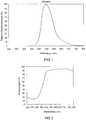
- FIG. 1 A concrete example of the highly efficient green emitting phosphor is in FIG. 1 shown. This is the emission of the phosphor SrSi 2 N 2 O 2 : (10% Eu 2+ ) in HT modification, in which the Eu content accounts for 10 mol% of the lattice sites occupied by Sr.
- the emission maximum is 545 nm, the mean dominant wavelength at 564 nm ( ⁇ dom).
- the excitation takes place at 460 nm.
- the FWHM is 84 nm.
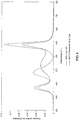
- FIG. 2 shows the diffuse reflection spectrum of this phosphor. It shows a pronounced minimum in the range below 430 nm, which thus demonstrates the good excitability in this area.
- the construction of a light source for white light is in Figure 3a, 3b shown explicitly.
- the light source is a type LED semiconductor device 6 having a first InGaN type chip 1 with a peak emission wavelength of, for example 460 nm, and a second InGaAlP chip 2 having a peak emission wavelength of, for example, 620 nm, and finally a luminescence conversion LED type semiconductor device having a third InGaN chip 3 having a primary peak emission wavelength of 460 nm, for example.
- the semiconductor device 6 is different embedded in an opaque base housing 8 similar elements.
- This solution has the great advantage of being tunable in a wide range of color temperatures by changing the relative intensities of the three LEDs by electronic control 7.
- a comparison, see Table 1, with the previously available solution with three primary emitting LEDs (RGB, where green was realized by an InGaN LED with ⁇ dom 526) shows impressively the superiority of the new solution.
- Fig. 3a shows an LED 6 in magnification.
- FIG. 4 shows the emission of such an illumination system as a spectral distribution (intensity in arbitrary units) over the wavelength (in nm).
- the dashed line shows the old solution (three primary emitting LEDs) compared to the new solution (two primary emitting LEDs and a green luminescence conversion LED) for a 4000 K color temperature.
- the particular advantage of using a long wavelength primary light source (450 to 465 nm) for the green luminescence conversion LED is that it avoids problems with aging and degradation of the package and resin or phosphor, resulting in a long life.
- a UV LED (about 380 nm) is used as the primary light source for the green luminescence conversion LED, in which case problems with aging and degradation of housing and resin or phosphor must be avoided as far as possible by additional measures known per se such as careful choice of housing material, adding UV-resistant resin components.
- the big advantage of this solution is the very high efficiency of typically 30 lm / W that can be achieved with it. ⁇ I> tab.
- a solution with two LEDs is used as the white-emitting semiconductor component.
- the basic structure is similar to in WO 01/41215 described.
- a first luminescence conversion LED provides the blue and green components.
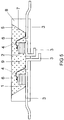
- An InGaN chip 1 having a primary peak emission wavelength of, for example, 460 nm is embedded in an opaque base housing 8 in the region of a cavity 9.
- a second LED 2 of the type InGaAlP which emits red, similar to the first embodiment, is accommodated in the cavity 9.
- the chips have separate controllable separate connections 3. In each case one of the terminals 3 is connected via a bonding wire 4 to the chip 1, 2.
- the recess has an inclined wall 7, which serves as a reflector for the primary radiation of the chips 1, 2.
- the recess 9 is filled with a potting compound 5, which contains as main components (80 to 90 wt .-%) typically a silicone casting resin (or Epoxidg discernharz) and phosphor pigments 6 (less than 15 wt .-%). Other minor proportions include methyl ether and Aerosil.
- This narrow common cavity design is possible because the red LED 2 with primary emission at 645 nm is not absorbed or converted by the green phosphor. This shows the importance of a narrow half-width (FWHM below 90 nm, preferably below 80 nm) as an example.
- FWHM narrow half-width
- the disadvantage of this extremely compact solution presented for the first time is the lack of tunability compared to the three-LED solution.
- the illumination system is also suitable in particular for the concept of adaptive illumination, in which the light color or also the brightness of the illumination system can be set according to freely selectable predetermined criteria or adapted to the brightness of the environment in a suitable manner.
Landscapes
- Chemical & Material Sciences (AREA)
- Inorganic Chemistry (AREA)
- Engineering & Computer Science (AREA)
- Materials Engineering (AREA)
- Organic Chemistry (AREA)
- Luminescent Compositions (AREA)
- Led Device Packages (AREA)
Applications Claiming Priority (2)
| Application Number | Priority Date | Filing Date | Title |
|---|---|---|---|
| DE10344332 | 2003-09-24 | ||
| PCT/DE2004/002135 WO2005030903A1 (de) | 2003-09-24 | 2004-09-24 | Hocheffizientes beleuchtungssystem auf led-basis mit verbesserter farbwiedergabe |
Publications (2)
| Publication Number | Publication Date |
|---|---|
| EP1670875A1 EP1670875A1 (de) | 2006-06-21 |
| EP1670875B1 true EP1670875B1 (de) | 2019-08-14 |
Family
ID=34384255
Family Applications (1)
| Application Number | Title | Priority Date | Filing Date |
|---|---|---|---|
| EP04786851.8A Expired - Lifetime EP1670875B1 (de) | 2003-09-24 | 2004-09-24 | Hocheffizientes beleuchtungssystem auf led-basis mit verbesserter farbwiedergabe |
Country Status (7)
| Country | Link |
|---|---|
| US (1) | US7825574B2 (da) |
| EP (1) | EP1670875B1 (da) |
| JP (1) | JP4457110B2 (da) |
| KR (1) | KR101131648B1 (da) |
| CN (1) | CN1886483B (da) |
| TW (1) | TWI350009B (da) |
| WO (1) | WO2005030903A1 (da) |
Families Citing this family (40)
| Publication number | Priority date | Publication date | Assignee | Title |
|---|---|---|---|---|
| TW200523340A (en) * | 2003-09-24 | 2005-07-16 | Patent Treuhand Ges Fur Elek Sche Gluhlampen Mbh | Hochefeizienter leuchtstoff |
| US7851988B2 (en) * | 2003-09-24 | 2010-12-14 | Osram Gesellschaft mit beschränkter Haftung | Green-emitting LED |
| US7066623B2 (en) * | 2003-12-19 | 2006-06-27 | Soo Ghee Lee | Method and apparatus for producing untainted white light using off-white light emitting diodes |
| DE102006016548B9 (de) | 2005-04-15 | 2021-12-16 | Osram Gmbh | Blau bis Gelb-Orange emittierender Leuchtstoff und Lichtquelle mit derartigem Leuchtstoff |
| WO2007070821A2 (en) * | 2005-12-13 | 2007-06-21 | Ilight Technologies, Inc. | Illumination device with hue transformation |
| EP1964184A2 (en) * | 2005-12-14 | 2008-09-03 | Koninklijke Philips Electronics N.V. | Solid-state light source and method of producing light of a desired color point |
| WO2007088966A1 (ja) * | 2006-02-02 | 2007-08-09 | Mitsubishi Chemical Corporation | 複合酸窒化物蛍光体、それを用いた発光装置、画像表示装置、照明装置及び蛍光体含有組成物、並びに、複合酸窒化物 |
| DE102006008300A1 (de) | 2006-02-22 | 2007-08-30 | Patent-Treuhand-Gesellschaft für elektrische Glühlampen mbH | Leuchtstoff und Lichtquelle mit derartigem Leuchtstoff sowie Herstellverfahren für den Leuchtstoff |
| KR100828891B1 (ko) * | 2006-02-23 | 2008-05-09 | 엘지이노텍 주식회사 | Led 패키지 |
| DK176593B1 (da) | 2006-06-12 | 2008-10-13 | Akj Inv S V Allan Krogh Jensen | Intelligent LED baseret lyskilde til erstatning af lysstofrör |
| CN101106856B (zh) * | 2006-07-10 | 2012-01-25 | 东芝照明技术株式会社 | 照明装置 |
| CN101536199A (zh) * | 2006-11-10 | 2009-09-16 | 皇家飞利浦电子股份有限公司 | 包括单片陶瓷发光转换器的照明系统 |
| EP2103187B1 (en) * | 2006-12-12 | 2010-05-26 | Inverto NV | Led lighting that has continuous and adjustable color temperature (ct), while maintaining a high cri |
| KR100946015B1 (ko) * | 2007-01-02 | 2010-03-09 | 삼성전기주식회사 | 백색 발광장치 및 이를 이용한 lcd 백라이트용 광원모듈 |
| DE102007010244A1 (de) * | 2007-02-02 | 2008-08-07 | Osram Opto Semiconductors Gmbh | Anordnung und Verfahren zur Erzeugung von Mischlicht |
| US7857994B2 (en) | 2007-05-30 | 2010-12-28 | GE Lighting Solutions, LLC | Green emitting phosphors and blends thereof |
| JP2011515536A (ja) * | 2008-03-21 | 2011-05-19 | ナノグラム・コーポレイション | 金属シリコン窒化物または金属シリコンオキシ窒化物のサブミクロン蛍光体粒子およびこれらの粒子を合成する方法 |
| KR100924912B1 (ko) * | 2008-07-29 | 2009-11-03 | 서울반도체 주식회사 | 웜화이트 발광장치 및 그것을 포함하는 백라이트 모듈 |
| JP5308773B2 (ja) * | 2008-10-30 | 2013-10-09 | スタンレー電気株式会社 | 半導体発光装置 |
| JP5342867B2 (ja) * | 2008-12-19 | 2013-11-13 | スタンレー電気株式会社 | 半導体発光装置及び駆動方法 |
| KR101396583B1 (ko) | 2009-09-14 | 2014-05-20 | 서울반도체 주식회사 | 웜화이트 발광장치 및 그것을 포함하는 백라이트 모듈 |
| JP2011071272A (ja) | 2009-09-25 | 2011-04-07 | Toshiba Corp | 半導体発光装置及びその製造方法 |
| WO2011044931A1 (de) * | 2009-10-14 | 2011-04-21 | Osram Gesellschaft mit beschränkter Haftung | LEUCHTVORRICHTUNG ZUR ERZEUGUNG EINES WEIßEN MISCHLICHTS |
| US8395312B2 (en) * | 2010-04-19 | 2013-03-12 | Bridgelux, Inc. | Phosphor converted light source having an additional LED to provide long wavelength light |
| TW201202391A (en) * | 2010-07-14 | 2012-01-16 | Forward Electronics Co Ltd | Phosphor composition for AC LED and AC LED manufactured by using the same |
| KR101225002B1 (ko) * | 2010-09-27 | 2013-01-22 | 삼성전자주식회사 | 형광체 및 이의 제조방법 |
| US8912554B2 (en) | 2011-06-08 | 2014-12-16 | Micron Technology, Inc. | Long wavelength light emitting device with photoluminescence emission and high quantum efficiency |
| KR101772588B1 (ko) | 2011-08-22 | 2017-09-13 | 한국전자통신연구원 | 클리어 컴파운드 에폭시로 몰딩한 mit 소자 및 그것을 포함하는 화재 감지 장치 |
| US8919975B2 (en) * | 2011-11-09 | 2014-12-30 | Cree, Inc. | Lighting device providing improved color rendering |
| CN104080886B (zh) * | 2012-06-27 | 2017-05-24 | 国立研究开发法人物质·材料研究机构 | 荧光体及其制备方法、发光装置及图像显示装置 |
| WO2014124537A1 (en) * | 2013-02-14 | 2014-08-21 | Verisante Technology, Inc. | Method and apparatus for optical measurements under ambient light conditions |
| AT14515U1 (de) | 2013-07-23 | 2015-12-15 | Tridonic Jennersdorf Gmbh | LED-Modul mit hohem Farbwiedergabeindex |
| DE102014205705B4 (de) | 2014-03-27 | 2020-11-05 | Carl Zeiss Industrielle Messtechnik Gmbh | Leuchttisch geeignet für Anwendungen in der Metrologie sowie Koordinatenmessgerät mit einem solchen Leuchttisch |
| JP2014150293A (ja) * | 2014-05-30 | 2014-08-21 | Mitsubishi Electric Corp | 発光装置 |
| US9799804B2 (en) | 2014-10-28 | 2017-10-24 | Matrix Lighting Ltd. | Light-emitting device with near full spectrum light output |
| US10090434B2 (en) | 2015-02-26 | 2018-10-02 | Apple Inc. | Illumination device having dual-emitting light emitting diode (LED) die structures |
| CN105368451B (zh) * | 2015-11-26 | 2017-07-28 | 华东师范大学 | 一种荧光增强的氧氮化物发光材料及其制备方法 |
| DE102016206524A1 (de) | 2016-04-19 | 2017-10-19 | Osram Gmbh | LED zur Emission von Beleuchtungsstrahlung |
| DE102016210236B4 (de) | 2016-06-09 | 2019-04-18 | Carl Zeiss Industrielle Messtechnik Gmbh | Verfahren und Koordinatenmessgerät zur metrologischen Vermessung von Werkstücken mit Hilfe eines Leuchttischs |
| CN108485667B (zh) * | 2018-03-28 | 2020-09-22 | 青岛科技大学 | 一种新型的发光颜色可调至白光的荧光粉及其制备方法 |
Family Cites Families (24)
| Publication number | Priority date | Publication date | Assignee | Title |
|---|---|---|---|---|
| US4897319A (en) | 1988-07-19 | 1990-01-30 | Planar Systems, Inc. | TFEL device having multiple layer insulators |
| WO1997048138A2 (en) | 1996-06-11 | 1997-12-18 | Philips Electronics N.V. | Visible light emitting devices including uv-light emitting diode and uv-excitable, visible light emitting phosphor, and method of producing such devices |
| US6255670B1 (en) * | 1998-02-06 | 2001-07-03 | General Electric Company | Phosphors for light generation from light emitting semiconductors |
| US6158882A (en) * | 1998-06-30 | 2000-12-12 | Emteq, Inc. | LED semiconductor lighting system |
| TW417842U (en) | 1998-09-28 | 2001-01-01 | Koninkl Philips Electronics Nv | Lighting system |
| US6495964B1 (en) | 1998-12-18 | 2002-12-17 | Koninklijke Philips Electronics N.V. | LED luminaire with electrically adjusted color balance using photodetector |
| US6686691B1 (en) | 1999-09-27 | 2004-02-03 | Lumileds Lighting, U.S., Llc | Tri-color, white light LED lamps |
| EP1142033A1 (en) * | 1999-09-27 | 2001-10-10 | LumiLeds Lighting U.S., LLC | A light emitting diode device that produces white light by performing complete phosphor conversion |
| EP1104799A1 (en) | 1999-11-30 | 2001-06-06 | Patent-Treuhand-Gesellschaft für elektrische Glühlampen mbH | Red emitting luminescent material |
| US6513949B1 (en) | 1999-12-02 | 2003-02-04 | Koninklijke Philips Electronics N.V. | LED/phosphor-LED hybrid lighting systems |
| DE19964252A1 (de) * | 1999-12-30 | 2002-06-06 | Osram Opto Semiconductors Gmbh | Oberflächenmontierbares Bauelement für eine LED-Weißlichtquelle |
| EP1161754B1 (en) * | 2000-01-06 | 2006-09-06 | Koninklijke Philips Electronics N.V. | Luminaire and light-emitting panel |
| JP2002076434A (ja) * | 2000-08-28 | 2002-03-15 | Toyoda Gosei Co Ltd | 発光装置 |
| US6411046B1 (en) | 2000-12-27 | 2002-06-25 | Koninklijke Philips Electronics, N. V. | Effective modeling of CIE xy coordinates for a plurality of LEDs for white LED light control |
| DE10105800B4 (de) * | 2001-02-07 | 2017-08-31 | Osram Gmbh | Hocheffizienter Leuchtstoff und dessen Verwendung |
| US6632379B2 (en) * | 2001-06-07 | 2003-10-14 | National Institute For Materials Science | Oxynitride phosphor activated by a rare earth element, and sialon type phosphor |
| DE10137042A1 (de) | 2001-07-31 | 2003-02-20 | Patent Treuhand Ges Fuer Elektrische Gluehlampen Mbh | Planare Lichtquelle auf LED-Basis |
| DE10147040A1 (de) | 2001-09-25 | 2003-04-24 | Patent Treuhand Ges Fuer Elektrische Gluehlampen Mbh | Beleuchtungseinheit mit mindestens einer LED als Lichtquelle |
| DE10153615C1 (de) | 2001-10-31 | 2003-07-24 | Osram Opto Semiconductors Gmbh | Verfahren zur Herstellung von elektronischen Bauteilen |
| DE10203795B4 (de) | 2002-01-31 | 2021-12-09 | OSRAM Opto Semiconductors Gesellschaft mit beschränkter Haftung | Verfahren zur Herstellung eines Halbleiterbauelements |
| AU2003221442A1 (en) * | 2002-03-22 | 2003-10-08 | Nichia Corporation | Nitride phosphor and method for preparation thereof, and light emitting device |
| EP1413618A1 (en) | 2002-09-24 | 2004-04-28 | Osram Opto Semiconductors GmbH | Luminescent material, especially for LED application |
| ATE329479T1 (de) | 2002-10-14 | 2006-06-15 | Koninkl Philips Electronics Nv | Lichtemittierendes bauelement mit einem eu(ii)- aktivierten leuchtstoff |
| US6717353B1 (en) * | 2002-10-14 | 2004-04-06 | Lumileds Lighting U.S., Llc | Phosphor converted light emitting device |
-
2004
- 2004-09-24 WO PCT/DE2004/002135 patent/WO2005030903A1/de active Application Filing
- 2004-09-24 US US10/574,021 patent/US7825574B2/en active Active
- 2004-09-24 TW TW093128944A patent/TWI350009B/zh active
- 2004-09-24 CN CN2004800347223A patent/CN1886483B/zh not_active Expired - Lifetime
- 2004-09-24 JP JP2006527270A patent/JP4457110B2/ja not_active Expired - Lifetime
- 2004-09-24 EP EP04786851.8A patent/EP1670875B1/de not_active Expired - Lifetime
- 2004-09-24 KR KR1020067007851A patent/KR101131648B1/ko active IP Right Grant
Non-Patent Citations (1)
| Title |
|---|
| None * |
Also Published As
| Publication number | Publication date |
|---|---|
| KR101131648B1 (ko) | 2012-03-28 |
| EP1670875A1 (de) | 2006-06-21 |
| US20070069643A1 (en) | 2007-03-29 |
| WO2005030903A1 (de) | 2005-04-07 |
| TW200518366A (en) | 2005-06-01 |
| US7825574B2 (en) | 2010-11-02 |
| JP2007507065A (ja) | 2007-03-22 |
| KR20060115731A (ko) | 2006-11-09 |
| JP4457110B2 (ja) | 2010-04-28 |
| CN1886483B (zh) | 2010-06-16 |
| TWI350009B (en) | 2011-10-01 |
| CN1886483A (zh) | 2006-12-27 |
Similar Documents
| Publication | Publication Date | Title |
|---|---|---|
| EP1670875B1 (de) | Hocheffizientes beleuchtungssystem auf led-basis mit verbesserter farbwiedergabe | |
| EP1664239B1 (de) | Weiss emittierende led mit definierter farbtemperatur | |
| DE60307415T2 (de) | Fotolumineszierende stoffe für leuchtdioden, und leuchtdiode | |
| EP2264762B1 (de) | Beleuchtungseinheit mit mindestens einer LED als Lichtquelle | |
| EP1987114B1 (de) | Leuchtstoff und lichtquelle mit derartigem leuchststoff sowie herstellverfahren für den leuchtstoff | |
| EP1352431B2 (de) | Lichtquelle mit einem lichtemittlierenden element | |
| DE102007035592B4 (de) | Temperaturstabiler Leuchtstoff, Verwendung eines Leuchtstoffs und Verfahren zur Herstellung eines Leuchtstoffs | |
| EP1966345B1 (de) | Rot emittierender leuchtstoff und lichtquelle mit einem derartigen leuchtstoff | |
| DE102006016548B4 (de) | Blau bis Gelb-Orange emittierender Leuchtstoff und Lichtquelle mit derartigem Leuchtstoff | |
| WO2006081803A1 (de) | Gelb emittierender leuchtstoff und lichtquelle mit derartigem leuchtstoff | |
| EP1670876B1 (de) | Hocheffizienter leuchtstoff | |
| DE10241140A1 (de) | Beleuchtungseinheit mit mindestens einer LED als Lichtquelle | |
| EP2275512B1 (de) | Grün emittierende LED | |
| EP1774600A2 (de) | Lichtquelle mit niedriger farbtemperatur | |
| DE10360546A1 (de) | Leuchtstoff und Lichtquelle mit derartigem Leuchtstoff | |
| DE202004021351U1 (de) | Licht emittierende Vorrichtung | |
| DE102004051395A1 (de) | Hocheffizienter stabiler Oxinitrid-Leuchtstoff | |
| EP2491095B1 (de) | Leuchtstoff und lichtquelle mit derartigem leuchtstoff | |
| DE102005037455A1 (de) | Weißlicht-Leuchtdiode | |
| DE112019001792B4 (de) | Leuchtstoff und beleuchtungsvorrichtung | |
| DE112009001977T5 (de) | Verfahren zur Herstellung eines ß-SiAION-Leuchtstoffs |
Legal Events
| Date | Code | Title | Description |
|---|---|---|---|
| PUAI | Public reference made under article 153(3) epc to a published international application that has entered the european phase |
Free format text: ORIGINAL CODE: 0009012 |
|
| 17P | Request for examination filed |
Effective date: 20060322 |
|
| AK | Designated contracting states |
Kind code of ref document: A1 Designated state(s): BE DE FR GB IT NL |
|
| DAX | Request for extension of the european patent (deleted) | ||
| RBV | Designated contracting states (corrected) |
Designated state(s): BE DE FR GB IT NL |
|
| RIN1 | Information on inventor provided before grant (corrected) |
Inventor name: BRUNNER, HERBERT Inventor name: FIEDLER, TIM Inventor name: ZACHAU, MARTIN Inventor name: JERMANN, FRANK |
|
| RAP1 | Party data changed (applicant data changed or rights of an application transferred) |
Owner name: OSRAM OPTO SEMICONDUCTORS GMBH Owner name: PATENT-TREUHAND-GESELLSCHAFT FUER ELEKTRISCHE GLUE |
|
| RAP1 | Party data changed (applicant data changed or rights of an application transferred) |
Owner name: OSRAM OPTO SEMICONDUCTORS GMBH Owner name: PATENT-TREUHAND-GESELLSCHAFT FUER ELEKTRISCHE GLUE |
|
| 17Q | First examination report despatched |
Effective date: 20120319 |
|
| STAA | Information on the status of an ep patent application or granted ep patent |
Free format text: STATUS: EXAMINATION IS IN PROGRESS |
|
| GRAP | Despatch of communication of intention to grant a patent |
Free format text: ORIGINAL CODE: EPIDOSNIGR1 |
|
| STAA | Information on the status of an ep patent application or granted ep patent |
Free format text: STATUS: GRANT OF PATENT IS INTENDED |
|
| INTG | Intention to grant announced |
Effective date: 20190308 |
|
| GRAS | Grant fee paid |
Free format text: ORIGINAL CODE: EPIDOSNIGR3 |
|
| GRAA | (expected) grant |
Free format text: ORIGINAL CODE: 0009210 |
|
| STAA | Information on the status of an ep patent application or granted ep patent |
Free format text: STATUS: THE PATENT HAS BEEN GRANTED |
|
| AK | Designated contracting states |
Kind code of ref document: B1 Designated state(s): BE DE FR GB IT NL |
|
| REG | Reference to a national code |
Ref country code: GB Ref legal event code: FG4D Free format text: NOT ENGLISH |
|
| REG | Reference to a national code |
Ref country code: DE Ref legal event code: R096 Ref document number: 502004015819 Country of ref document: DE |
|
| RAP2 | Party data changed (patent owner data changed or rights of a patent transferred) |
Owner name: PATENT-TREUHAND-GESELLSCHAFT FUER ELEKTRISCHE GLUE Owner name: OSRAM OPTO SEMICONDUCTORS GMBH |
|
| REG | Reference to a national code |
Ref country code: NL Ref legal event code: MP Effective date: 20190814 |
|
| PG25 | Lapsed in a contracting state [announced via postgrant information from national office to epo] |
Ref country code: NL Free format text: LAPSE BECAUSE OF FAILURE TO SUBMIT A TRANSLATION OF THE DESCRIPTION OR TO PAY THE FEE WITHIN THE PRESCRIBED TIME-LIMIT Effective date: 20190814 |
|
| PG25 | Lapsed in a contracting state [announced via postgrant information from national office to epo] |
Ref country code: IT Free format text: LAPSE BECAUSE OF FAILURE TO SUBMIT A TRANSLATION OF THE DESCRIPTION OR TO PAY THE FEE WITHIN THE PRESCRIBED TIME-LIMIT Effective date: 20190814 |
|
| REG | Reference to a national code |
Ref country code: DE Ref legal event code: R097 Ref document number: 502004015819 Country of ref document: DE |
|
| PLBE | No opposition filed within time limit |
Free format text: ORIGINAL CODE: 0009261 |
|
| STAA | Information on the status of an ep patent application or granted ep patent |
Free format text: STATUS: NO OPPOSITION FILED WITHIN TIME LIMIT |
|
| 26N | No opposition filed |
Effective date: 20200603 |
|
| REG | Reference to a national code |
Ref country code: BE Ref legal event code: MM Effective date: 20190930 |
|
| PG25 | Lapsed in a contracting state [announced via postgrant information from national office to epo] |
Ref country code: BE Free format text: LAPSE BECAUSE OF NON-PAYMENT OF DUE FEES Effective date: 20190930 |
|
| GBPC | Gb: european patent ceased through non-payment of renewal fee |
Effective date: 20191114 |
|
| PG25 | Lapsed in a contracting state [announced via postgrant information from national office to epo] |
Ref country code: GB Free format text: LAPSE BECAUSE OF NON-PAYMENT OF DUE FEES Effective date: 20191114 |
|
| PG25 | Lapsed in a contracting state [announced via postgrant information from national office to epo] |
Ref country code: FR Free format text: LAPSE BECAUSE OF NON-PAYMENT OF DUE FEES Effective date: 20191014 |
|
| PGFP | Annual fee paid to national office [announced via postgrant information from national office to epo] |
Ref country code: DE Payment date: 20230920 Year of fee payment: 20 |