EP1667066B1 - Einrichtung, verfahren und programm zur visuellen verarbeitung, integrierte schaltung, display-einrichtung, abbildungs-einrichtung und mobil-informationsendgerät - Google Patents
Einrichtung, verfahren und programm zur visuellen verarbeitung, integrierte schaltung, display-einrichtung, abbildungs-einrichtung und mobil-informationsendgerät Download PDFInfo
- Publication number
- EP1667066B1 EP1667066B1 EP04773249.0A EP04773249A EP1667066B1 EP 1667066 B1 EP1667066 B1 EP 1667066B1 EP 04773249 A EP04773249 A EP 04773249A EP 1667066 B1 EP1667066 B1 EP 1667066B1
- Authority
- EP
- European Patent Office
- Prior art keywords
- signal
- value
- visual processing
- input signal
- gradation
- Prior art date
- Legal status (The legal status is an assumption and is not a legal conclusion. Google has not performed a legal analysis and makes no representation as to the accuracy of the status listed.)
- Expired - Lifetime
Links
Images


Classifications
-
- G—PHYSICS
- G06—COMPUTING OR CALCULATING; COUNTING
- G06T—IMAGE DATA PROCESSING OR GENERATION, IN GENERAL
- G06T5/00—Image enhancement or restoration
- G06T5/90—Dynamic range modification of images or parts thereof
- G06T5/92—Dynamic range modification of images or parts thereof based on global image properties
-
- G—PHYSICS
- G06—COMPUTING OR CALCULATING; COUNTING
- G06T—IMAGE DATA PROCESSING OR GENERATION, IN GENERAL
- G06T5/00—Image enhancement or restoration
- G06T5/20—Image enhancement or restoration using local operators
-
- G—PHYSICS
- G06—COMPUTING OR CALCULATING; COUNTING
- G06T—IMAGE DATA PROCESSING OR GENERATION, IN GENERAL
- G06T5/00—Image enhancement or restoration
- G06T5/40—Image enhancement or restoration using histogram techniques
-
- G—PHYSICS
- G06—COMPUTING OR CALCULATING; COUNTING
- G06T—IMAGE DATA PROCESSING OR GENERATION, IN GENERAL
- G06T5/00—Image enhancement or restoration
- G06T5/73—Deblurring; Sharpening
- G06T5/75—Unsharp masking
-
- G—PHYSICS
- G06—COMPUTING OR CALCULATING; COUNTING
- G06T—IMAGE DATA PROCESSING OR GENERATION, IN GENERAL
- G06T5/00—Image enhancement or restoration
- G06T5/90—Dynamic range modification of images or parts thereof
-
- G—PHYSICS
- G06—COMPUTING OR CALCULATING; COUNTING
- G06T—IMAGE DATA PROCESSING OR GENERATION, IN GENERAL
- G06T2207/00—Indexing scheme for image analysis or image enhancement
- G06T2207/10—Image acquisition modality
- G06T2207/10024—Color image
Definitions
- the present invention relates to visual processing devices, in particular to visual processing devices that perform visual processing such as spatial processing or gradation processing of an image signal.
- visual processing devices in particular to visual processing devices that perform visual processing such as spatial processing or gradation processing of an image signal.
- Separate aspects of the invention relate to visual processing methods, visual processing programs, integrated circuits, display devices, image-capturing devices, and portable information terminals.
- a display processor for an ultrasonic imaging system includes a two-dimensional filter to generate a smootehed image signal Ip from a high spatial resolution image signal I D .
- Ip is optimized for high contrast resolution and good tissue differentiation
- I D is optimized for high detail resolution and the display of fine structural details
- Ip and I D are applied as addressing inputs to a look-up table that provides an output image signal I O that combines both detail resolution of I D and contrast resolution of I P.
- I O can display detail resolution as brightness and contrast resolution as color.
- I O can also be formed as a weighted combination or sum of Ip and I D .
- Spatial processing and gradation processing are known as techniques for visually processing image signals of an original image.
- Spatial processing involves using the pixels around a pixel to be filtered when processing that pixel.
- the technique of using an image signal that has been subjected to spatial processing to perform contrast enhancement or dynamic range (DR) compression, for example, of an original image is known.
- contrast enhancement the difference between the original image and the blur signal (the sharp component of the image) is added to the original image, sharpening the image.
- DR compression a portion of the blur signal is subtracted from the original image, compressing the dynamic range.
- Gradation processing is processing in which a lookup table (LUT) is used to transform a pixel value for each pixel being processed without regard for the pixels around the pixel being processed, and is also referred to as "gamma correction.”
- LUT lookup table
- transformation of the pixel value is performed using a LUT that produces a gradation of gray levels that appear frequently (whose area is large) in the original image.
- gradation processing using a LUT include gradation processing in which a single LUT is chosen and used for the entire original image (histogram equalization) and gradation processing in which the original image is partitioned into a plurality of image regions and a LUT is chosen and used for each image region (local histogram equalization) (for example, see JP 2000-57335A (pg. 3, Figs. 13 to 16 )).
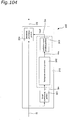
- Fig. 104 shows a visual processing device 300 that partitions an original image into a plurality of image regions and chooses a LUT to use for each image region.
- the visual processing device 300 is provided with an image partitioning portion 301 that partitions an original image that has been input as an input signal IS into a plurality of image regions Sm (1 ⁇ m ⁇ n; where n is the number of partitions of the original image), a gradation transformation curve derivation portion 310 that derives a gradation transformation curve Cm for each image region Sm, and a gradation processing portion 304 that obtains the gradation transformation curves Cm and subjects each image region Sm to gradation processing and outputs the result as an output signal OS.
- the gradation transformation curve derivation portion 310 comprises a histogram creation portion 302 that creates a brightness histogram Hm for each image region Sm, and a gradation curve creation portion 303 that creates a gradation transformation curve Cm for each image region Sm from the brightness histogram Hm that has been created.
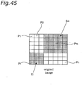
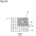
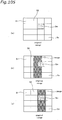
- the image partitioning portion 301 partitions an original image that has been received as an input signal IS into a plurality (n) of image regions (see Fig. 105(a) ).
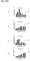
- the histogram creation portion 302 creates a brightness histogram Hm for each image region Sm (see Fig. 106 ).
- Each brightness histogram Hm shows the distribution of the brightness values of all pixels in an image region Sm. That is, the horizontal axes in the brightness histograms Hm shown in Fig. 106(a) to (d) show the brightness level of the input signal IS and the vertical axes show the pixel number.
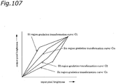
- the gradation curve creation portion 303 cumulates the "pixel number" of the brightness histogram Hm in the order of their brightness and this cumulative curve is taken as a gradation transformation curve Cm (see Fig. 107 ).
- the horizontal axis shows the brightness value of the pixels of the image region Sm in the input signal IS
- the vertical axis shows the brightness value of the pixels of the image region Sm in the output signal OS.
- the gradation processing portion 304 obtains the gradation transformation curve Cm and transforms the brightness value of the pixels in the image region Sm in the input signal IS based on the gradation transformation curve Cm. By doing this, a gradient is established between the most frequent gradations in each block, and this increases the sense of contrast for each block.
- Visual processing that combines spatial processing and gradation processing also is known. Conventional visual processing that combines spatial processing and gradation processing is described below using Fig. 108 and Fig. 109 .
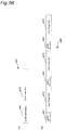
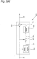
- Fig. 108 shows a visual processing device 400 that performs edge enhancement and contrast enhancement utilizing unsharp masking.
- the visual processing device 400 shown in Fig. 108 is provided with a spatial processing portion 401 that performs spatial processing with respect to the input signal IS and outputs an unsharp signal US, a subtracting portion 402 that subtracts the unsharp signal US from the input signal IS and outputs a difference signal DS, an enhancing portion 403 that performs enhancement of the difference signal DS and outputs an enhanced signal TS, and a summing portion 404 that takes the sum of the input signal IS and the enhanced signal TS and outputs an output signal OS.
- a spatial processing portion 401 that performs spatial processing with respect to the input signal IS and outputs an unsharp signal US
- a subtracting portion 402 that subtracts the unsharp signal US from the input signal IS and outputs a difference signal DS
- an enhancing portion 403 that performs enhancement of the difference signal DS and outputs an enhanced signal TS
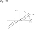
- Fig. 109 shows the enhancement functions R1 to R3.
- the horizontal axis in Fig. 109 marks the difference signal DS and the vertical axis marks the enhanced signal TS.
- the enhancement function R1 is an enhancement function that is linear with respect to the difference signal DS.
- the enhancement function R2 is a non-linear enhancement function with respect to the difference signal DS, and is a function that inhibits extreme contrasts.
- a greater inhibitory effect is exhibited with respect to an input x having a large absolute value (where x is the value of the difference signal DS).
- the enhancement function R2 is expressed by a graph having a smaller slope the larger the absolute value of the input x.
- the enhancement function R3 is a non-linear enhancement function for the difference signal DS that inhibits the noise component in small amplitudes. That is, a greater inhibitory effect (an inhibitory effect due to a larger inhibition rate) is attained with respect to an input x having a small absolute value (where x is the value of the difference signal DS).
- the enhancement function R3 is expressed by a graph having a larger slope the greater the absolute value of the input x.
- the enhancing portion 403 can use any of these enhancement functions R1 to R3.
- the difference signal DS is the sharp component of the input signal IS.
- the intensity of the difference signal DS is transformed and added to the input signal IS.
- the output signal OS is the input signal IS in which the edges and the contrast have been enhanced.
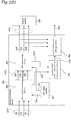
- Fig. 110 shows a visual processing device 406 that improves the local contrast (intensity) (for example, see Japanese Patent JP 2832954 (pg. 2, Fig. 5 )).
- the visual processing device 406 shown in Fig. 110 is provided with a spatial processing portion 407, a subtracting portion 408, a first transformation portion 409, a multiplying portion 410, a second transformation portion 411, and a summing portion 412.
- the spatial processing portion 407 performs spatial processing with respect to the input signal IS and outputs an unsharp signal US.
- the subtracting portion 408 subtracts the unsharp signal US from the input signal IS and outputs a difference signal DS.
- the first transformation portion 409 outputs an amplification coefficient signal GS for locally amplifying the difference signal DS based on the intensity of the unsharp signal US.
- the multiplying portion 410 takes the product of the difference signal DS and the amplification coefficient signal GS and outputs a contrast enhanced signal HS in which the difference signal DS has been locally amplified.
- the second transformation portion 411 locally corrects the intensity of the unsharp signal US and outputs a corrected unsharp signal AS.
- the summing portion 412 takes the sum of the contrast enhanced signal HS and the corrected unsharp signal AS and outputs an output signal OS.
- the amplification coefficient signal GS is a non-linear weight coefficient that locally corrects the contrast in portions of the input signal IS where the contrast is unsuitable. For this reason, portions of the input signal IS having suitable contrast are output unchanged, and those portions with an unsuitable contrast are corrected and then output.
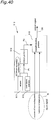
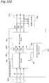
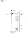
- Fig. 111 shows a visual processing device 416 that performs compression of the dynamic range (for example, see JP 2001-298619A (pg. 3, Fig. 9 )).
- the visual processing device 416 shown in Fig. 111 is provided with a spatial processing portion 417 that performs spatial processing with respect to the input signal IS and outputs an unsharp signal US, a LUT computation portion 418 that uses a LUT to perform an inverse transformation of the unsharp signal US to produce a LUT processed signal LS which it then outputs, and a summing portion 419 that takes the sum of the input signal IS and the LUT processed signal LS and outputs an output signal OS.
- the LUT processed signal LS is added to the input signal IS to compress the dynamic range of low-frequency components of the input signal IS (frequency components lower than the cutoff frequency of the spatial processing portion 417). As a result, the dynamic range of the input signal IS is compressed while its high-frequency components are retained.
- the visual processing device according to the present invention is defined in claim 1.
- the visual processing device of the invention it is possible to provide a visual processing device that has a hardware configuration that does not depend on the visual processing that is to be achieved.
- a visual processing method according to the invention is defined in claim 3 and a processor used for an image output device according to the invention is defined in claim 4.
- the first embodiment describes a visual processing device that employs a two-dimensional LUT.
- the second embodiment describes a visual processing device that performs correction of the ambient light when ambient light is present in the environment in which the image is to be displayed.
- the third embodiment describes applied examples of the first embodiment and the second embodiment.
- the fourth through sixth embodiments describe visual processing devices that achieve a gradation processing that increases the visual effect.
- the seventh embodiment describes a visual processing device that performs visual processing using a suitable blur signal.
- the eighth embodiment describes applied examples of the fourth through seventh embodiments.
- the ninth embodiment describes applied examples of the first through eighth embodiments.
- the tenth embodiment describes an example in which the visual processing devices of the above embodiments are adopted in a display device.
- the eleventh embodiment describes an example in which the visual processing devices of the above embodiments are adopted in an image-capturing device.
- a visual processing device 1 that employs a two-dimensional LUT is described below as a first embodiment of the present invention using Figs. 1 to 10 .
- a modified example of this visual processing device is described using Figs. 11 to 14 .
- a visual processing device that achieves visual processing that is equivalent to that of the visual processing device 1 is described using Figs. 15 to 23 .
- the visual processing device 1 is a device for performing visual processing such as spatial processing and gradation processing of an image signal.
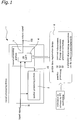
- Fig. 1 shows the basic structure of the visual processing device 1, which performs visual processing of an image signal (input signal IS) and outputs the result as a visually processed image (output signal OS).
- the visual processing device 1 is provided with a spatial processing portion 2 that performs spatial processing of the luminance value of each pixel of an original image that has been obtained as an input signal IS and outputs the result as an unsharp signal US, and a visual processing portion 3 that performs visual processing of the original image using the input signal IS and the unsharp signal US for the same pixel and outputs the result as an output signal OS.
- the spatial processing portion 2 for example obtains the unsharp signal US with a low-pass spatial filter that permits the passage of only the low-frequency space of the input signal IS.
- a low-pass spatial filter it is possible to use a FIR (Finite Impulse Response)-type low-pass spatial filter or an IIR (Infinite Impulse Response)-type low-pass spatial filter, which are commonly used to create unsharp signals.
- the visual processing portion 3 has a two-dimensional LUT 4 that lists the relationship between the input signal IS and the unsharp signal US, and the output signal OS, and references the two-dimensional LUT 4 with the input signal IS and the unsharp signal US and outputs an output signal OS.
- Matrix data referred to as profile data are registered to the two-dimensional LUT 4.
- the profile data has a row (or column) for each pixel value of the input signal IS and a column (or row) for each pixel value of the unsharp signal US, and the pixel values of the output signal OS that correspond to the combination of the input signal IS and the unsharp signal US are stored as elements of the rows and columns.
- the profile data are registered to the two-dimensional LUT 4 by a profile data registration device 8 that is provided in or connected to the visual processing device 1.
- the profile data registration device 8 stores data of a plurality of profiles that have been created in advance by a personal computer (PC) or the like.
- the profile data registration device 8 can be used to change the profile data registered to the two-dimensional LUT 4, and this allows a variety of types of visual processing to be achieved.
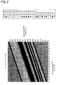
- FIG. 2 An example of the profile data is shown in Fig. 2 .
- the profile data shown in Fig. 2 causes the visual processing device 1 to execute processing equivalent to that of the visual processing device 400 shown in Fig. 108 .
- the profile data takes the form of a 64 ⁇ 64 matrix in which the values of the upper six bits of the luminance values of the 8-bit input signal IS are shown in the column direction (vertical direction) and the value of the upper six bits of the luminance value of the 8-bit unsharp signal US are shown in the row direction (horizontal direction).
- the value of the output signal OS is expressed in 8 bits value as the matrix element corresponding to the two luminance values.
- the visual processing device 1 performs processing equivalent to processing by the visual processing device 400 (see Fig. 108 ) using the enhancement function R1 (see Fig. 109 ).
- the value C obtained from Eq. M11 may be a negative value.
- the element of the profile data corresponding to the value A of the input signal IS and the value B of the unsharp signal US may be set to the value 0.
- the value C obtained from Eq. M11 may be saturated. That is, it may exceed the maximum value of 255 that can be expressed with 8 bits.
- the element of the profile data corresponding to the value A of the input signal IS and the value B of the unsharp signal US may be set to the value 255.
- the elements of the profile data found in this manner are shown by contour line.
- Equation M12 processing equal to that of the visual processing device 406 shown in Fig. 110 can be achieved.
- the function R5 is that of the first transformation portion 409 outputting an amplification coefficient signal GS from the unsharp signal US
- the function R6 is that of the second transformation portion 411 outputting a corrected unsharp signal AS from the unsharp signal US.
- Equation M13 processing equivalent to that of the visual processing device 416 shown in Fig. 111 can be achieved.
- the function R8 is that of outputting a LUT processed signal LS from the unsharp signal US.
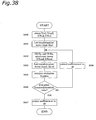
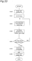
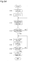
- Fig. 3 shows a flowchart that describes the visual processing method of the visual processing device 1.
- the visual processing method shown in Fig. 3 is a method for performing visual processing of an input signal IS (see Fig. 1 ), and is achieved by the hardware in the visual processing device 1.
- an input signal IS is spatially processed by the low-pass spatial filter (step S11) to obtain an unsharp signal US.
- the value of the two-dimensional LUT 4 that corresponds to the input signal IS and the unsharp signal US is looked up and this value is output as the output signal OS (step S12).
- the above processing is performed for each pixel that is received as an input signal IS.
- each step of the visual processing method shown in Fig. 3 can also be achieved on a computer, for example, as a visual processing program.
- the interpolating portion may be provided in the visual processing portion 3 and may output as an output signal OS a value that is obtained by linearly interpolating the values stored in the two-dimensional LUT 4.
- Fig. 4 shows a visual processing portion 500 provided with an interpolating portion 501, as a modified example of the visual processing portion 3.
- the visual processing portion 500 is provided with a two-dimensional LUT 4 that lists the relationship between an input signal IS and an unsharp signal US and a pre-interpolation output signal NS, and the interpolating portion 501, which receives the pre-interpolation output signal NS, the input signal IS and the unsharp signal US and outputs an output signal OS.
- the two-dimensional LUT 4 stores the values of the pre-interpolation output signal NS for the values of the upper six bits of the luminance of the 8-bit input signal IS and the values of the upper six bits of the luminance of the 8-bit unsharp signal US.
- the values of the pre-interpolation output signal NS are for example stored as 8-bit values.
- the two-dimensional LUT 4 receives the 8-bit value of the input signal IS and the 8-bit value of the unsharp signal US, it outputs the values of the four pre-interpolation output signals NS corresponding to the section including each of the values.
- the section including each of the values is the section surrounded by the four pre-interpolation output signals NS stored for the combinations of (the value of the upper six bits of the input signal IS, the value of the upper six bits of the unsharp signal US), (the smallest six-bit value that exceeds the value of the upper six bits of the input signal IS, the value of the upper six bits of the unsharp signal US), (the value of the upper six bits of the input signal IS, the smallest six-bit value that exceeds the value of the upper six bits of the unsharp signal US), and (the smallest six-bit value that exceeds the value of the upper six bits of the input signal IS, the smallest six-bit value that exceeds the value of the upper six bits of the unsharp signal US).
- the value of the lower two bits of the input signal IS and the value of the lower two bits of the unsharp signal US are input to the interpolating portion 501, and using these values, the interpolating portion 501 performs linear interpolation of the values of the four pre-interpolation output signals NS output by the two-dimensional LUT 4. More specifically, the interpolating portion 501 uses the value of the lower two bits of the input signal IS and the value of the lower two bits of the unsharp signal US to calculate the weighted mean of the values of the four pre-interpolation output signals NS, and outputs this as the output signal OS.
- interpolating portion 501 it is also possible for the interpolating portion 501 to perform linear interpolation of only one of either the input signal IS or the unsharp signal US.
- pixels having the same darkness that are present at different areas within the image are not transformed uniformly but instead can be made brighter or darker taking into account surrounding information, and this allows each region of the image to be adjusted to an ideal brightness. More specifically, a background that has the same darkness as the hair of a person in the image can be brightened without changing the darkness of the hair. Moreover, it is also possible to perform visual processing in which the gradation is maintained, even for those image regions in which the pixel values become saturated after visual processing according to a linear function.
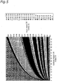
- Fig. 5 shows an example of such profile data.
- the profile data shown in Fig. 5 are profile data with which the visual processing device 1 can perform contrast enhancement that is suited for the visual characteristics.
- the profile data are expressed as a 64 ⁇ 64 matrix, in which the value of the upper six bits of the luminance value of the 8-bit input signal IS is shown in the column direction (vertical direction) and the value of the upper six bits of the luminance value of the 8-bit unsharp signal US is shown in the row direction (horizontal direction).
- the output signal OS is expressed as an 8-bit value as the matrix element corresponding to the two luminance values.
- the transformation function F1 is a common logarithmic function.
- the inverse transformation function F2 is an exponential function (antilog) that functions as the inverse function of the common logarithmic function.
- the enhancement function F3 is any of the enhancement functions R1 to R3 explained using Fig. 109 .
- the value C obtained from Eq. M14 may be a negative value.
- the element of the profile data corresponding to the value A of the input signal IS and the value B of the unsharp signal US may be set to the value 0.
- the value C that is obtained from Eq. M14 may be saturated. That is, it may exceed the maximum value of 255 that can be expressed with 8 bits.
- the element of the profile data corresponding to the value A of the input signal IS and the value B of the unsharp signal US may be set to the value 255.
- each element of the profile data found in this manner is shown by a contour line.
- Non-linear profile data are described in more specific detail in the section ⁇ Profile Data> below.
- the profile data stored in the profile data registration device 8 are created by a PC that is disposed outside of the visual processing device 1.
- the profile data registration device 8 obtains the profile data from the PC over a network or via a recording medium.
- the profile data registration device 8 registers data of a plurality of profiles to be stored to the two-dimensional LUT 4 in accordance with a predetermined condition. This is described in greater detail using Figs. 6 to 8 . It should be noted that portions having substantially the same function as in the visual processing device 1, which was described above using Fig. 1 , are assigned identical reference numerals and further description thereof is omitted.
- Fig. 6 is a block diagram of a visual processing device 520 that determines the image of an input signal IS, and based on the results of this determination, switches the profile data registered to the two-dimensional LUT 4.
- the visual processing device 520 in addition to the same structural components as the visual processing device 1 shown in Fig. 1 , also has a profile data registration portion 521 that has the same function as the profile data registration device 8.
- the visual processing device 520 is further provided with an image determination portion 522.
- the image determination portion 522 receives an input signal IS and outputs determination results SA of the input signal IS.
- the profile data registration portion 521 receives the determination results SA and outputs profile data PD selected based on those determination results SA.
- the image determination portion 522 determines the image of the input signal IS.
- the brightness of the input signal IS is determined by obtaining a pixel value such as the luminance or the brightness of the input signal IS.
- the profile data registration portion 521 obtains the determination results SA, and based on these determination results SA, it switches the profile data PD and outputs the result. More specifically, if the input signal IS is determined to be bright, then profile data that compress the dynamic range, for example, are selected. By doing this, the contrast can be maintained even for images that are bright overall. Also, a profile with an output signal OS having a suitable dynamic range for the characteristics of the device that will display the output signal OS is selected.
- the visual processing device 520 is capable of suitably visually processing an input signal IS.
- the image determination portion 522 may determine an image characteristic, such as the spatial frequency, in addition to a pixel value such as the luminance or the brightness of the input signal IS.
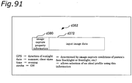
- Fig. 7 is a block diagram of a visual processing device 525 that switches the profile data registered to the two-dimensional LUT 4 based on the results of an input from an input device for inputting conditions relating to the brightness.
- the visual processing device 525 in addition to the same structural components as the visual processing device 1 shown in Fig. 1 , also is provided with a profile data registration portion 526 that has the same function as the profile data registration device 8.
- the visual processing device 525 is provided with an input device 527 to which it is connected through a wired or a wireless connection. More specifically, the input device 527 can be achieved for example by an input button provided on, or remote control for, a device that handles images, such as a computer, a television, a digital camera, a portable telephone, a PDA, a printer, or a scanner, that outputs an output signal OS.
- the input device 527 is an input device for inputting conditions related to the brightness, and for example is provided with switches such as “bright” and “dark.”
- the input device 527 outputs the input results SB through control by a user.
- the profile data registration portion 526 obtains the input results SB, and based on the input results SB switches the profile data PD and outputs the result. More specifically, for example if the user has input "bright,” then a profile for compressing the dynamic range of the input signal IS, for example, is selected and this is output as the profile data PD. Thus, the contrast can be maintained even if the device for displaying the output signal OS has been placed in a "bright" environment.
- the conditions related to the brightness can be not only the conditions related to the brightness of the ambient light around the medium that will output the output signal, such: as a computer, digital camera, portable telephone, or PDA, but also can be the conditions related to the brightness of the medium itself to which the output signal will be output, such as the printer paper.
- the conditions can also be related to the brightness of the medium by which the input signal is received, such as the scanner paper.
- the input device 527 can be a device that directly causes the profile data registration portion 526 to change the profile rather than a device that simply inputs conditions related to brightness.
- the input device 527 can display a list of the profile data in addition to the conditions to the related to the brightness, and have the user make a selection from among these.
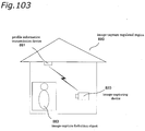
- the input device 527 can also be a device for authenticating the user.
- the input device 527 can be a device such as a camera that authenticates the user or a device through which the user inputs his or her user name.
- profile data for inhibiting extreme luminance changes are selected.
- Fig. 8 is a block diagram of a visual processing device 530 that switches the profile data registered to the two-dimensional LUT 4 based on the detection results from a luminance detection portion for detecting two types of brightness.
- the visual processing device 530 in addition to the same structural components as the visual processing device 1 shown in Fig. 1 , also has a profile data registration portion 531 that has the same function as the profile data registration device 8.
- the visual processing device 530 is further provided with a brightness detection portion 532.
- the brightness detection portion 532 comprises the image determination portion 522 and the input device 527.
- the image determination portion 522 and the input device 527 are the same as those described using Figs. 6 and 7 .
- the brightness detection portion 532 receives the input signal IS as input, and outputs the determination results SA from the image determination portion 522 and the input results SB from the input device 527 as detection results.
- the profile data registration portion 531 receives the determination results SA and the input results SB as input, and based on the determination results SA and the input results SB, switches the profile data PD and outputs the result. More specifically, for example if the ambient light is "bright" and it also has been determined that the input signal IS is bright, then a profile that compresses the dynamic range of the input signal IS, for example, is selected and this is output as the profile data PD. Thus, the contrast can be maintained when the output signal OS is displayed.
- the profile data registration portions can be connected to the visual processing devices over a network as a server provided with a plurality of profile data sets or as a plurality of servers each provided with profile data.
- the network is a wired or wireless connection means that is capable of communication, such as a dedicated telephone line, a public telephone line, the Internet, or a LAN.
- the determination results SA and the input results SB both are transferred from the visual processing device side to the profile data registration portion side over the same network.
- the profile data registration device 8 is provided with a plurality of profile data sets, and different visual processing was achieved by switching which of these is registered to the two-dimensional LUT 4.
- the visual processing device 1 it is also possible for the visual processing device 1 to be provided with a plurality of two-dimensional LUT, each being provided with profile data for achieving a different visual processing. In this case, the visual processing device 1 achieves different visual processing by switching which of the two-dimensional LUTs receives the input or by switching which of the two-dimensional LUTs to receive the output from.
- the profile data registration device 8 may be provided with a device that creates new profile data based on data of a plurality of profiles and registers the profile data that are created to the two-dimensional LUT 4.
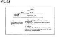
- Fig. 9 is a block diagram that primarily illustrates a profile data registration device 701, as a modified example of the profile data registration device 8.
- the profile data registration device 701 is a device for switching the profile data that are registered to the two-dimensional LUT 4 of the visual processing device 1.
- the profile data registration device 701 comprises a profile data registration portion 702 to which a plurality of profile data sets are registered, a profile creation execution portion 703 that creates new profile data based on the data of a plurality of profiles, a parameter input portion 706 for inputting parameters with which to create new profile data, and a control portion 705 that controls these portions.
- Data of a plurality of profiles are registered to the profile data registration portion 702 as in the profile data registration device 8 or the profile data registration portions shown in Fig. 6 to Fig. 8 , and the profile data that have been selected through a control signal C10 from the control portion 705 are read out.
- data of two selected profiles are read out from the profile data registration portion 702, namely first selected profile data d10 and second selected profile data d11.
- the profile data that are read from the profile data registration portion 702 are determined based on input from the parameter input portion 706.
- the control portion 705 specifies the profile data to be read out with a control signal c10 and also specifies the value of the degree of synthesis of the respective profile data using a control signal c12.
- the profile creation execution portion 703 is provided with a profile creation portion 704 that produces a created profile data d6, which are new profile data, from the first selected profile data d10 and the second selected profile data d11.
- the profile creation portion 704 obtains the first selected profile data d10 and the second selected profile data d11 from the profile data registration portion 702. It also obtains the control signal c12, which specifies the degree of synthesis of the respective selected profile data, from the control portion 705.
- the profile creation portion 704 then applies the value [k] of the degree of synthesis specified by the control signal c12 to a value [m] of the first selected profile data d10 and a value [n] of the second selected profile data d11 to create created profile data d6 having a value [1].
- the two-dimensional LUT 4 obtains the created profile data d6 created by the profile creation portion 704 and stores the obtained value in an address that is specified by a count signal c11 of the control portion 705.
- the created profile data d6 are associated with the same image signal value as the selected profile data that were used to create the created profile data d6.
- profile data that achieve different visual processing can be used to create new profile data that achieve yet different visual processing.
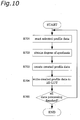
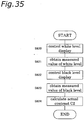
- the visual processing profile creation method that is executed by the visual processing device provided with the profile data registration device 701 is described using Fig. 10 .
- the address of the profile data registration portion 702 is specified at a fixed count period by a count signal c10 from the control portion 705, and the image signal value that is stored in the specified address is read out (step S701). More specifically, the control portion 705 outputs a count signal c10 in correspondence with a parameter that has been input by the parameter input portion 706.
- the count signal c10 specifies the addresses of two profile data, each of which achieves different visual processing, in the profile data registration portion 702. From this signal, the first selected profile data d10 and the second selected profile data d11 are read from the profile data registration portion 702.
- the profile creation portion 704 obtains the control signal c12, which specifies the degree of synthesis, from the control portion 705 (step S702).
- the profile creation portion 704 then applies the value [k] of the degree of synthesis specified by the control signal c12 to the value [m] of the first selected profile data d10 and the value [n] of the second selected profile data d11 to create a created profile data d6 having the value [1] (step S703).
- the created profile data d6 are written to the two-dimensional LUT 4 (step S704).
- the address to which the data are written is specified by a count signal c11 from the control portion 705 that is given to the two-dimensional LUT 4.
- the control portion 705 determines whether or not processing has finished for all of the selected profile data (step S705), and repeats the processes of step S701 to step S705 until this processing is finished.
- the new profile data stored in the two-dimensional LUT 4 in this manner are then used to execute visual processing.
- profile data that achieve different visual processing can be used to create new profile data that achieve yet different visual processing, and this visual processing can be performed. That is, it is possible to achieve visual processing to any degree simply by providing the profile data registration portion 702 with a small number of profile data, and thus the memory capacity of the profile data registration portion 702 can be reduced.
- the profile data registration device 701 can be provided not only in the visual processing device 1 shown in Fig. 1 , but also in any of the visual processing devices of Figs. 6 to 8 .
- the profile data registration portion 702 and the profile creation execution portion 703 are used in place of the profile data registration portions 521, 526, and 531 shown in Figs. 6 to 8 , respectively, and the parameter input portion 706 and the control portion 705 are used in place of the image determination portion 522 of Fig. 6 , the input device 527 of Fig. 7 , and the brightness detection portion 532 of Fig. 8 .
- the visual processing device can also be a device that transforms the brightness of the input signal IS.
- a visual processing device 901 that transforms the brightness is described using Fig. 11 .
- the visual processing device 901 is a device that transforms the brightness of an input signal IS', and comprises a processing portion 902 that performs a predetermined processing with respect to the input signal IS' and outputs a processed signal US', and a transformation portion 903 that uses the input signal IS' and the processed signal US' to perform transformation of the input signal IS'.
- the processing portion 902 operates in the same manner as the spatial processing portion 2 (see Fig. 1 ), and performs spatial processing of the input signal IS'. It should be noted that it can also perform spatial processing such as that discussed in the above ⁇ Modified Example> (3).
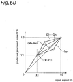
- the transformation portion 903 is provided with a two-dimensional LUT like the visual processing portion 3 and outputs an output signal OS' (value [y]) based on the input signal IS' (value [x]) and the processed signal US' (value [z]).
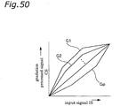
- the values of the elements of the two-dimensional LUT of the transformation portion 903 are determined by applying the value [x] of the input signal IS' to gain or offset that has been determined in correspondence with the value of the function fk(z), which is related to the extent of change in brightness.
- the function fk(z) related to the extent of change in brightness is hereinafter referred to as the "extent change function.”
- this function is referred to as a "transformation function,” and the transformation functions (a) to (d) are examples thereof.
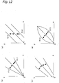
- Figs. 12(a) to (d) show the relationship between the input signal IS' and the output signal OS' when the extent change function fk(z) has been changed.
- the extent change function f1(z) acts as gain of the input signal IS'.
- the gain of the input signal IS' changes depending on the value of the extent change function f1(z), and this changes the value [y] of the output signal OS'.
- Fig. 12(a) shows the change in the relationship between the input signal IS' and the output signal OS' for various values of the extent change function f1(z).
- the value [y] of the output signal increases as the extent change function f1(z) becomes larger (f1(z)>1). That is, the image after transformation becomes brighter.
- the value [y] of the output signal decreases as the extent change function f1(z) becomes smaller (f1(z) ⁇ 1). That is, the image after transformation becomes darker.
- the extent change function f1(z) is a function in which the smallest value in the defined domain of the value [z] does not become less than [0].
- the value [y] of the output signal is outside the valid range of values, then it may be clipped to the valid range of values. For example, if the value [y] of the output signal exceeds the value [1], then it is possible to clip it to the value [1], and if the value [y] of the output signal is below the value [0], then it can be clipped to the value [0]. This also applies to the other transformation functions (b) through (d) discussed below.
- the extent change function f2(z) acts as offset of the input signal IS'.
- the offset of the input signal IS' changes depending on the value of the extent change function f2(z), and this changes the value [y] of the output signal OS'.
- Fig. 12(b) shows the change in the relationship between the input signal IS' and the output signal OS' when the value of the extent change function f2(z) is changed.
- the value [y] of the output signal increases as the extent change function f2(z) becomes larger (f2(z)>0). That is, the image after transformation becomes brighter.
- the value [y] of the output signal decreases as the extent change function f2(z) becomes smaller (f2(z) ⁇ 0). That is, the image after transformation becomes darker.
- the extent change function f1(z) acts as gain of the input signal IS'.
- the extent change function f2(z) also acts as offset of the input signal IS'.
- the gain of the input signal IS' changes depending on the value of the extent change function f1(z)
- the offset of the input signal IS' changes depending on the value of the extent change function f2(z)
- Fig. 12(c) shows the change in the relationship between the input signal IS' and the output signal OS' when the values of the extent change function f1(z) and the extent change function f2(z) are changed.
- the value [y] of the output signal increases as the extent change function f1(z) and the extent change function f2(z) become larger. That is, the image after transformation becomes brighter.
- the value [y] of the output signal decreases as the extent change function f1(z) and the extent change function f2(z) become smaller. That is, the image after transformation becomes darker.
- the extent change function f2(z) determines the "power" of the "power function.”
- the input signal IS' changes depending on the value of the extent change function f2(z), and this changes the value [y] of the output signal OS'.
- Fig. 12(d) shows the change in the relationship between the input signal IS' and the output signal OS' when the value of the extent change function f2(z) is changed.
- the value [y] of the output signal increases as the extent change function f2(z) becomes larger (f2(z)>0). That is, the image after transformation becomes brighter.
- the value [y] of the output signal decreases as the extent change function f2(z) becomes smaller (f2(z) ⁇ 0). That is, the image after transformation becomes darker. If the extent change function f2(z) is the value [0], then transformation with respect to the input signal IS' is not performed.
- the value [x] is a value obtained by normalizing the value of the input signal IS' to the range of [0] to [1].
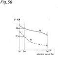
- Figs. 13(a) and (b) show examples in which the extent change function f1(z) and the extent change function f2(z) both decrease monotonically.
- Each shows three graphs (a1 to a3, b1 to b3), and each of these graphs is an example of a function that decreases monotonically.
- the extent change function f1(z) is a function that has a value range that spans the value [1], and is a function in which the minimum value with respect to the defined range of the value [z] is not less than the value [0].
- the extent change function f2(z) is a function that has a value range that spans the value [0].
- the value [z] of the processed signal US' is small.
- the value of the extent change function for a small value [z] is large. That is, when a two-dimensional LUT that has been created based on a transformation function (a) through (d) is used, then portions in the image in which the area of darkness is large are made brighter. Thus, for example in an image that is captured with backlight, the dark portions are fixed in sections in which the area of darkness is large, and this improves the visual effect.
- the value [z] of the processed signal US' is large.
- the value of the extent change function for a large value [z] is small. That is, when a two-dimensional LUT that has been created based on a transformation function (a) through (d) is used, portions in the image in which the area of brightness is large are made darker. Thus, for example in an image having bright portions such as the sky, blooming is fixed in the portions in which the area of brightness is large, and this improves the visual effect.
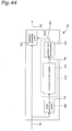
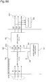
- Fig. 14 shows the configuration of a visual processing device 905.
- the visual processing device 905 is a device that performs visual processing of an input signal IS", and comprises a first processing portion 906a that performs a first predetermined processing with respect to the input signal IS" and outputs a first processed signal U1, a second processing portion 906b that performs a second predetermined processing with respect to the input signal IS" and outputs a second processed signal U2, and a transformation portion 908 that uses the input signal IS", the first processed signal U1, and the second processed signal U2 to perform transformation of the input signal IS".
- the first processing portion 906a and the second processing portion 906b both operate in the same manner as the spatial processing portion 2 (see Fig. 1 ), and perform spatial processing of the input signal IS". It should be noted that it is also possible for them to perform spatial processing such as that described in the ⁇ Modified Example> (3) above.
- first processing portion 906a and the second processing portion 906b differ in the size of the region of the surrounding pixels that are used for the spatial processing.
- the first processing portion 906a uses the surrounding pixels that are included in a region of 30 pixels vertically by 30 pixels horizontally with the target pixel in the center (small unsharp signal), whereas the second processing portion 906b uses the surrounding pixels that are included in the region of 90 pixels vertically by 90 pixels horizontally with the target pixel in the center (large unsharp signal).
- the region of surrounding pixels that is described here is only one example, and there is no limitation to this. It is preferable that the unsharp signal is created from a fairly wide region in order to obtain a sufficient visual processing effect.
- the transformation portion 908 is provided with a LUT, and outputs an output signal OS" (value [y]) based on the input signal IS" (value [x]), the first processed signal U1 (value [z1]), and the second processed signal U2 (value [z2]).
- the LUT that the transformation portion 903 is provided with is a three-dimensional LUT that stores values [y] of the output signal OS" with respect to the values [x] of the input signal IS", the values [z1] of the first processed signal U1, and the values [z2] of the second processed signal U2.
- This three-dimensional LUT is capable of achieving the processing discussed in the above-described and later-described embodiments, but here the three-dimensional LUT is described for the ⁇ Case of Transforming the Brightness of the Input Signal IS">> and the ⁇ Case of Enhancement Transformation of the Input Signal IS">>.
- the transformation portion 908 performs a transformation to brighten the input signal IS" if the value [z1] of the first processed signal U1 is small. However, the extent to which it is brightened is kept low if the value [z2] of the second processed signal US also is small.
- the value of each element of the three-dimensional LUT of the transformation portion 903 is determined based on the following transformation function (e) or (f).
- the extent change functions f11(z1) and f12(z2) are the same function as the extent change function f1(z) described in ⁇ Modified Example> (8) above.
- the extent change function f11(z1) and the extent change function f12(z2) are different functions.
- [f11(z1)/f12(z2)] acts as the gain of the input signal IS
- the gain of the input signal IS changes in accordance with the value of the first processed signal U1 and the value of the second processed signal U2, and this changes the value [y] of the output signal OS".
- the extent change functions f21(z1) and f22(z2) are the same function as the extent change function f2(z) described in ⁇ Modified Example> (8) above.
- the extent change function f21(z1) and the extent change function f22(z2) are different functions.
- [f21(z1) - f22(z2)] acts as the offset of the input signal IS
- the offset of the input signal IS changes in accordance with the value of the first processed signal U1 and the value of the second processed signal U2, and this changes the value [y] of the output signal OS".
- processing by the transformation portion 908 is not limited to processing using a three-dimensional LUT, and it can also be processing in which the same computations as those of the transformation functions (e) or (f), for example, are performed.
- transformation by the transformation portion 908 is transformation that enhances the input signal IS"
- the visual processing device 1 can also be provided with profile data for achieving various types of visual processing other than that described above.
- profile data for achieving various types of visual processing are described below, for each showing the equation that characterizes the profile data and the structure of a visual processing device that achieves visual processing that is equivalent to the visual processing device 1 provided with those profile data.
- Each set of profile data is determined based on a mathematical equation that includes a computation for enhancing the values calculated from the input signal IS and the unsharp signal US.
- this computation for enhancing is a computation that is achieved by a non-linear enhancement function, for example.
- the first profile data are determined in accordance with a computation that includes a function for enhancing the difference between the respective transformed values that are obtained by performing a predetermined transformation with respect to the input signal IS and the unsharp signal US.
- Equation M1 F2(F1(A)+F3(F1(A)-F1(B))) (hereinafter, this is referred to as Equation M1) using the value A of the input signal IS, the value B of the unsharp signal US, the transformation function F1, the inverse transformation function F2 of the transformation function, and an enhancement function F3.
- the transformation function F1 is a common logarithmic function.
- the inverse transformation function F2 is an exponential function (antilog) that functions as the inverse function of the common logarithmic function.
- the enhancement function F3 is any of the enhancement functions R1 to R3 explained using Fig. 109 .
- Fig. 15 shows a visual processing device 11 that is equivalent to the visual processing device 1 in which the first profile data have been registered to the two-dimensional LUT 4.
- the visual processing device 11 is a device that outputs an output signal OS based on a computation that enhances the differences in the transformed values of the input signal IS and the unsharp signal US after the two have been subjected to a predetermined transformation.
- the input signal IS and the unsharp signal US are transformed to separate spaces and their respective differences are enhanced, and this allows for example enhancement that is suited for the visual characteristics to be achieved.
- the visual processing device 11 shown in Fig. 15 is provided with a spatial processing portion 12 that performs spatial processing on the luminance of each pixel of an original image that it has obtained as an input signal IS and outputs an unsharp signal US, and a visual processing portion 13 that uses the input signal IS and the unsharp signal US to perform visual processing of the original image and outputs an output signal OS.
- the spatial processing portion 12 performs the same operation as the spatial processing portion 2 of the visual processing device 1, and thus its further description is omitted.
- the visual processing portion 13 is provided with a signal space transformation portion 14 that performs transformation of the signal space of the input signal IS and the unsharp signal US and outputs a transformed input signal TIS and a transformed unsharp signal TUS, a subtracting portion 17 that receives the transformed input signal TIS as a first input and the transformed unsharp signal TUS as a second input and outputs a difference signal DS of the difference between the two, an enhancing portion 18 that receives the difference signal DS as input and outputs an enhanced signal TS that has been enhanced, a summing portion 19 that receives the transformed input signal TIS as a first input and the enhanced signal TS as a second input and sums the two to obtain a summed signal PS that it then outputs, and an inverse transformation portion 20 that receives the summed signal PS as an input and outputs an output signal OS.
- a signal space transformation portion 14 that performs transformation of the signal space of the input signal IS and the unsharp signal US and outputs a transformed input signal TIS and
- the signal space transformation portion 14 further includes a first transformation portion 15 that receives the input signal IS as input and outputs the transformed input signal TIS, and a second transformation portion 16 that receives the unsharp signal US as input and outputs the transformed unsharp signal TUS.
- the first transformation portion 15 uses the transformation function F1 to transform the input signal, which has the value A, to the transformed input signal TIS, which has the value F1(A).
- the second transformation portion 16 uses the transformation function F1 to transform the unsharp signal US, which has the value B, to the transformed unsharp signal TUS, which has the value F1(B).
- the subtracting portion 17 calculates the difference between the transformed input signal TIS having the value F1(A) and the transformed unsharp signal TUS having the value F1(B) and outputs a difference signal DS having the value F1(A) - F1(B).
- the enhancing portion 18 uses the enhancement function F3 to output an enhanced signal TS having a value F3(F1(A) - F1(B)) from the difference signal DS of the value F1(A) - F1(B).
- the summing portion 19 takes the sum of the transformed input signal TIS having the value F1(A) and the enhanced signal TS having the value F3(F1(A) - F1(B)) and outputs a summed signal PS that has a value F1(A) + F3(F1(A) - F1(B)).
- the inverse transformation portion 20 uses the inverse transformation function F2 to perform inverse transformation of the summed signal PS having the value F1(A) + F3(F1(A) - F1(B)), and outputs an output signal OS having the value F2(F1(A) + F3(F1(A) - F1(B)).
- the calculations using the transformation function F1, the inverse transformation function F2, and the enhancement function F3 each can be performed using a one-dimensional LUT for that function, or can be performed without using a LUT.
- the visual processing device 11 and the visual processing device 1 provided with the first profile data attain the same visual processing effects.
- the value of a particular element of the profile data found with Eq. M1 is outside of the range 0 ⁇ C ⁇ 255, then the value of that element can be set to either 0 or 255 in order to prevent the pixel signals after correction from becoming negative and failing or becoming saturated and failing. This can be achieved regardless of the bit length for expressing the elements of the profile data.
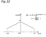
- the second profile data are determined by a computation that includes a function for enhancing the ratio between the input signal IS and the unsharp signal US.
- a computation that includes a function for enhancing the ratio between the input signal IS and the unsharp signal US.
- the second profile data are determined by a computation in which dynamic range compression is performed with respect to the ratio between the enhanced input signal IS and the unsharp signal US.
- dynamic range compression is performed with respect to the ratio between the enhanced input signal IS and the unsharp signal US.
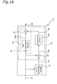
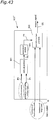
- Fig. 16 shows a visual processing device 21 that is equivalent to the visual processing device 1 in which the second profile data have been registered to the two-dimensional LUT 4.
- the visual processing device 21 is a device that outputs an output signal OS based on a computation that enhances the ratio between the input IS and the unsharp signal US. Thus, it is for example possible to achieve visual processing for enhancing the sharp component.
- the visual processing device 21 also outputs an output signal OS based on a computation in which dynamic range compression is performed with respect to the ratio between the enhanced input signal IS and the unsharp signal US.
- an output signal OS based on a computation in which dynamic range compression is performed with respect to the ratio between the enhanced input signal IS and the unsharp signal US.
- the visual processing device 21 shown in Fig. 16 is provided with a spatial processing portion 22 that executes spatial processing on the luminance value of each pixel of an original image that it has obtained as an input signal IS and outputs an unsharp signal US, and a visual processing portion 23 that uses the input signal IS and the unsharp signal US to perform visual processing of the original image and outputs an output signal OS.
- the spatial processing portion 22 performs the same operation as the spatial processing portion 2 of the visual processing device 1, and thus it will not be described further.
- the visual processing portion 23 is provided with a dividing portion 25 that takes the input signal IS as a first input and the unsharp signal US as a second input, and divides the input signal IS by the unsharp signal US to obtain a divided signal RS that it then outputs, an enhancing portion 26 that receives the divided signal RS as input and outputs an enhanced signal TS, and an output portion 27 that receives the input signal IS as a first input and the enhanced signal TS as a second input and outputs an output signal OS.
- a dividing portion 25 that takes the input signal IS as a first input and the unsharp signal US as a second input, and divides the input signal IS by the unsharp signal US to obtain a divided signal RS that it then outputs
- an enhancing portion 26 that receives the divided signal RS as input and outputs an enhanced signal TS
- an output portion 27 that receives the input signal IS as a first input and the enhanced signal TS as a second input and outputs an output signal OS.
- the output portion 27 is provided with a DR compression portion 28 that receives the input signal IS as input and outputs a DR compressed signal DRS that has been subjected to dynamic range (DR) compression, and a multiplying portion 29 that receives the DR compressed signal DRS as a first input and the enhanced signal TS as a second input and outputs an output signal OS.
- DR dynamic range
- the dividing portion 25 divides the input signal IS, which has the value A, by the unsharp signal US, which has the value B, and outputs a divided signal RS having the value A/B.
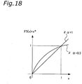
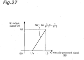
- the enhancing portion 26 uses the enhancement function F5 to output an enhanced signal TS having the value F5(A/B) from the divided signal RS having the value A/B.
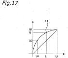
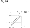
- the DR compression portion 28 uses the dynamic range compression function F4 to output a DR compressed signal DRS having the value F4(A) from the input signal IS, whose value is A.
- the multiplying portion 29 multiplies the DR compressed signal DRS, whose value is F4(A), and the enhanced signal TS, whose value is F5(A/B), and outputs an output signal OS having the value F4(A) ⁇ F5(A/B).
- the calculations using the dynamic range compression function F4 and the enhancement function F5 can each be performed using a one-dimensional LUT for that function, or can be performed without using a LUT.
- the visual processing device 21 and the visual processing device 1 provided with the second profile data achieve the same visual processing effects.
- the third profile data are determined based on a computation that includes a function for enhancing the ratio between the input signal IS and the unsharp signal US.
- a computation that includes a function for enhancing the ratio between the input signal IS and the unsharp signal US.
- the dynamic range compression function F4 is a direct proportion function of a proportional coefficient 1.
- Fig. 19 shows a visual processing device 31 that is equivalent to the visual processing device 1 in which the third profile data have been registered to the two-dimensional LUT 4.
- the visual processing device 31 is a device that outputs an output signal OS based on a computation that enhances the ratio between the input IS and the unsharp signal US. Thus, it is for example possible to achieve visual processing for enhancing the sharp component.
- the visual processing device 31 shown in Fig. 19 differs from the visual processing device 21 shown in Fig. 16 in that it is not provided with the DR compression portion 28.
- the visual processing device 31 shown in Fig. 19 is described below, assigning the same reference numerals to and omitting description of portions that perform the same operations as those of the visual processing portion 21 shown in Fig. 16 .
- the visual processing device 31 is provided with a spatial processing portion 22 that performs spatial processing of the luminance value of each pixel of an original image that it has obtained as an input signal IS and outputs an unsharp signal US, and a visual processing portion 32 that uses the input signal IS and the unsharp signal US to perform visual processing of the original image and outputs an output signal OS.
- the spatial processing portion 22 performs the same operation as the spatial processing portion 2 of the visual processing device 1, and thus it will not be described further.
- the visual processing portion 32 is provided with a dividing portion 25 that takes an input signal IS as a first input and an unsharp signal US as a second input, and divides the input signal IS by the unsharp signal US to obtain a divided signal RS that it then outputs, an enhancing portion 26 that receives the divided signal RS as input and outputs an enhanced signal TS, and a multiplying portion 33 that receives the input signal IS as a first input and the enhanced signal TS as a second input and outputs an output signal OS.
- the dividing portion 25 and the enhancing portion 26 perform the same operations as described with regard to the visual processing device 21 shown in Fig. 16 .
- the multiplying portion 33 multiplies the input signal IS, whose value is A, and the enhanced signal TS, whose value is value F5(A/B), and outputs an output signal OS having the value A ⁇ F5(A/B).
- the enhancement function F5 is the same as that shown in Fig. 18 .
- the calculation using the enhancement function F5 can be performed using a one-dimensional LUT for that function, or can be performed without using a LUT.
- the visual processing device 31 and the visual processing device 1 that has been provided with the third profile data achieve the same visual processing effect.
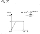
- the fourth profile data are determined based on a computation that includes a function for enhancing the difference between the input signal IS and the unsharp signal US in accordance with the value of the input signal IS. Due to this, it is for example possible to enhance the sharp component of the input signal IS, for example, in accordance with the value of the input signal IS. Thus, enhancement of the input signal IS can be performed suitably over a range including dark areas and light areas.
- the fourth profile data are determined based on a computation that adds to the enhanced value the value that is obtained by compressing the dynamic range of the input signal IS.
- Equation M4 F8(A) + F6(A) ⁇ F7(A-B) (hereinafter, this is referred to as Equation M4) using the value A of the input signal IS, the value B of the unsharp signal US, an enhancement amount adjustment function F6, an enhancement function F7, and a dynamic range compression function F8.
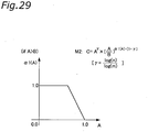
- the enhancement amount adjustment function F6 is a function that monotonically increases with respect to the value of the input signal IS. That is, when the value A of the input signal IS is small, the value of the enhancement amount adjustment function F6 also is small, and when the value A of the input signal IS is large, then the value of the enhancement amount adjustment function F6 also is large.
- the enhancement function F7 is any one of the enhancement functions R1 to R3 that were described using Fig. 109 .
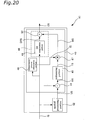
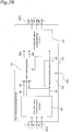
- Fig. 20 shows a visual processing device 41 that is equivalent to the visual processing device 1 in which the fourth profile data have been registered to the two-dimensional LUT 4.
- the visual processing device 41 is a device that outputs an output signal OS based on a computation for enhancing the difference between the input signal IS and the unsharp signal US in accordance with the value of the input signal IS. Due to this, it is for example possible to enhance the sharp component of the input signal IS, for example, in accordance with the value of the input signal IS. Thus, enhancement can be suitably performed from dark areas through light areas of the input signal IS.
- the visual processing device 41 outputs an output signal OS based on a computation that adds to the enhanced value, the value that is obtained by compressing the dynamic range of the input signal IS.
- the visual processing device 41 outputs an output signal OS based on a computation that adds to the enhanced value, the value that is obtained by compressing the dynamic range of the input signal IS.
- the visual processing device 41 shown in Fig. 20 is provided with a spatial processing portion 42 that performs spatial processing of the luminance value of each pixel of an original image that it has obtained as an input signal IS and outputs an unsharp signal US, and a visual processing portion 43 that uses the input signal IS and the unsharp signal US to perform visual processing of the original image and outputs an output signal OS.
- the spatial processing portion 42 performs the same operation as the spatial processing portion 2 of the visual processing device 1, and thus it will not be described further.
- the visual processing portion 43 is provided with a subtracting portion 44 that receives an input signal IS as a first input and an unsharp signal US as a second input and then outputs a difference signal DS of the difference between the two, an enhancing portion 45 that receives the difference signal DS as an input and outputs an enhanced signal TS, an enhancement amount adjustment portion 46 that receives the input signal IS as input and outputs an enhancement amount adjusted signal IC, a multiplying portion 47 that receives the enhancement amount adjusted signal IC as a first input and the enhanced signal TS as a second input and multiplies the enhancement amount adjusted signal IC and the enhanced signal TS to obtain a multiplied signal MS that it then outputs, and an output portion 48 that receives the input signal IS as a first input and the multiplied signal MS as a second input and outputs an output signal OS.
- a subtracting portion 44 that receives an input signal IS as a first input and an unsharp signal US as a second input and then outputs a difference signal DS of the difference between the
- the output portion 48 is provided with a DR compression portion 49 that receives the input signal IS as input and outputs a DR compressed signal DRS that has been subjected to dynamic range (DR) compression, and a summing portion 50 that receives the DR compressed signal DRS as a first input and the multiplied signal MS as a second input and outputs an output signal OS.
- DR dynamic range
- visual processing portion 43 The operation of visual processing portion 43 is described in further detail below.
- the subtracting portion 44 calculates the difference between the input signal IS, which has the value A, and the unsharp signal US, which has the value B, and outputs a difference signal DS having the value A-B.
- the enhancing portion 45 uses the enhancement function F7 to output an enhanced signal TS having the value F7(A-B) from the difference signal DS, which has the value A-B.
- the enhancement amount adjustment portion 46 uses the enhancement amount adjustment function F6 to output an enhancement amount adjusted signal IC having the value F6(A) from the input signal IS, which has the value A.
- the multiplying portion 47 multiplies the enhancement amount adjusted signal IC, which has the value F6(A), and the enhanced signal TS, which has the value F7(A-B), and outputs the result as a multiplied signal MS having the value F6(A) * F7(A-B).
- the DR compression portion 49 uses the dynamic range compression function F8 to output a DR compressed signal DRS having the value F8(A) from the input signal IS, which has the value A.
- the summing portion 50 takes the sum of the DR compressed signal DRS and the multiplied signal MS, which has the value F6(A) ⁇ F7(A-B), and outputs an output signal OS having the value F8(A) + F6(A) ⁇ F7(A-B).
- the calculations using the enhancement amount adjustment function F6, the enhancement function F7, and the dynamic range compression function F8 can each be performed using a one-dimensional LUT for that function, or can be performed without using a LUT.
- the visual processing device 41 and the visual processing device 1 provided with the fourth profile data achieve the same visual processing effects.
- the fifth profile data are determined based on a computation that includes a function for enhancing the difference between the input signal IS and the unsharp signal US in accordance with the value of the input signal IS. Due to this, it is for example possible to enhance the sharp component of the input signal IS, for example, in accordance with the value of the input signal IS. Thus, enhancement of the input signal IS can be performed suitably across dark areas to light areas.
- the dynamic range compression function F8 is a direct proportion function of a proportion coefficient 1.
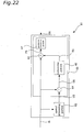
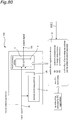
- Fig. 21 shows a visual processing device 51 that is equivalent to the visual processing device 1 in which the fifth profile data have been registered to the two-dimensional LUT 4.
- the visual processing device 51 is a device that outputs an output signal OS based on a computation for enhancing the difference between the input signal IS and the unsharp signal US in accordance with the value of the input signal IS. Due to this, it is for example possible to enhance the sharp component of the input signal IS, for example, in accordance with the value of the input signal IS. Thus, enhancement of the input signal IS can be suitably performed over a range that spans dark areas and light areas.
- the visual processing device 51 shown in Fig. 21 differs from the visual processing device 41 shown in Fig. 20 in that it is not provided with the DR compression portion 49.
- the visual processing device 51 shown in Fig. 21 is described below, assigning the same reference numerals to portions that perform the same operations as those of the visual processing portion 41 shown in Fig. 20 , and detailed description thereof is omitted.
- the visual processing device 51 is provided with a spatial processing portion 42 that executes spatial processing of the brightness value of each pixel of an original image that it has obtained as an input signal IS and outputs the result as an unsharp signal US, and a visual processing portion 52 that uses the input signal IS and the unsharp signal US to perform visual processing of the original image and outputs the result as an output signal OS.
- the spatial processing portion 42 performs the same operation as the spatial processing portion 2 of the visual processing device 1, and thus it will not be described further.
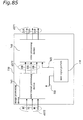
- the visual processing portion 52 is provided with a subtracting portion 44 that receives an input signal IS as a first input and an unsharp signal US as a second input and then outputs a difference signal DS of the difference between the two, an enhancing portion 45 that receives the difference signal DS as input and outputs an enhanced signal TS, an enhancement amount adjustment portion 46 that receives the input signal IS as input and outputs an enhancement amount adjusted signal IC, a multiplying portion 47 that receives the enhancement amount adjusted signal IC as a first input and the enhanced signal TS as a second input and multiplies the enhancement amount adjusted signal IC and the enhanced signal TS to obtain a multiplied signal MS that it then outputs, and a summing portion 53 that receives the input signal IS as a first input and the multiplied signal MS as a second input and outputs an output signal OS.
- a subtracting portion 44 that receives an input signal IS as a first input and an unsharp signal US as a second input and then outputs a difference signal DS of the difference
- the subtracting portion 44, the enhancing portion 45, the enhancement amount adjustment portion 46, and the multiplying portion 47 perform the same operations as those described with regard to the visual processing device 41 shown in Fig. 20 .
- the summing portion 53 takes the sum of the input signal IS, which has the value A, and the multiplied signal MS, which has the value F6(A) ⁇ F7(A-B), and outputs an output signal OS having the value A + F6(A) ⁇ F7(A-B).
- the calculations using the enhancement amount adjustment function F6 and the enhancement function F7 can each be performed using a one-dimensional LUT for that function, or can be performed without using a LUT.
- the visual processing device 51 and the visual processing device 1 provided with the fifth profile data achieve the same visual processing effects. Moreover, they achieve substantially the same visual processing effects as those attained by the visual processing device 41 and the visual processing device 1 provided with the fourth profile data.
- the sixth profile data are determined based on a computation that corrects the gradation of a value that is obtained by adding the value of the input signal IS to a value obtained by enhancing the difference between the input signal IS and the unsharp signal US.
- gradation correction is performed with respect to an input signal IS whose sharp component has been enhanced.
- Equation M6 F10(A + F9(A-B)) (hereinafter, this is referred to as Equation M6) using the value A of the input signal IS, the value B of the unsharp signal US, an enhancement function F9, and a gradation correction function F10.
- the enhancement function F9 is any one of the enhancement functions R1 to R3 that were described using Fig. 109 .
- the gradation correction function F10 is a function that is used in ordinary gradation correction, and for example is a gamma correction function, an S-shaped gradation correction function, or an inverted S-shaped gradation correction function.
- Fig. 22 shows a visual processing device 61 that is equivalent to the visual processing device 1 in which the sixth profile data have been registered to the two-dimensional LUT 4.
- the visual processing device 61 is a device that outputs an output signal OS based on a computation that corrects the gradation of the value obtained by adding the value of the input signal IS to a value that is obtained by enhancing the difference between the input signal IS and the unsharp signal US.
- gradation correction is performed with respect to an input signal IS whose sharp component has been enhanced.
- the visual processing device 61 shown in Fig. 22 is provided with a spatial processing portion 62 that performs spatial processing of the luminance value of each pixel of an original image that it has obtained as an input signal IS and outputs an unsharp signal US, and a visual processing portion 63 that uses the input signal IS and the unsharp signal US to perform visual processing of the original image and outputs an output signal OS.
- the spatial processing portion 62 performs the same operation as the spatial processing portion 2 of the visual processing device 1, and thus it will not be described further.
- the visual processing portion 63 is provided with a subtracting portion 64 that receives an input signal IS as a first input and an unsharp signal US as a second input and then outputs a difference signal DS of the difference between the two, an enhancing portion 65 that receives the difference signal DS as input and outputs an enhanced signal TS that has been enhanced, a summing portion 66 that receives the input signal IS as a first input and the enhanced signal TS as a second input and outputs a summed signal PS that is the sum of the two, and a gradation correction portion 67 that receives the summed signal PS as input and outputs an output signal OS.
- a subtracting portion 64 that receives an input signal IS as a first input and an unsharp signal US as a second input and then outputs a difference signal DS of the difference between the two
- an enhancing portion 65 that receives the difference signal DS as input and outputs an enhanced signal TS that has been enhanced
- a summing portion 66 that receives the input
- the subtracting portion 64 calculates the difference between the input signal IS, which has the value A, and the unsharp signal US, which has the signal B, and outputs a difference signal DS having the value A-B.
- the enhancing portion 65 uses the enhancement function F9 to output an enhanced signal TS having the value F9(A-B) from the difference signal DS, which has the value A-B.
- the summing portion 66 takes the sum of the input signal IS, which has the value A, and the enhanced signal TS, which has the value F9(A-B), and outputs a summed signal PS having the value A + F9(A-B).
- the gradation correction portion 67 uses the gradation correction function F10 to output an output signal OS having the value F10(A + F9(A-B)) from the summed signal PS, which has the value A + F9(A-B).
- the calculations using the enhancement function F9 and the gradation correction function F10 can each be performed using a one-dimensional LUT for that function, or can be performed without using a LUT.
- the visual processing device 61 and the visual processing device 1 furnished with the sixth profile data achieve the same visual processing effects.
- the seventh profile data are determined based on a computation that adds a value that is obtained by correcting the gradation of the input signal IS to a value that is obtained by enhancing the difference between the input signal IS and the unsharp signal US.
- enhancement of the sharp component and gradation correction of the input signal IS are performed independently.
- Equation M7 F12(A) + F11(A-B) (hereinafter, this is referred to as Equation M7) using the value A of the input signal IS, the value B of the unsharp signal US, an enhancement function F11, and a gradation correction function F12.
- the enhancement function F11 is any one of the enhancement functions R1 to R3 described using Fig. 109 .
- the gradation correction function F12 is for example a gamma correction function, an S-shaped gradation correction function, or an inverted S-shaped gradation correction function.
- Fig. 23 shows a visual processing device 71 that is equivalent to the visual processing device 1 in which the seventh profile data have been registered to the two-dimensional LUT 4.
- the visual processing device 71 is a device that outputs an output signal OS based on a computation that adds a value that is obtained by correcting the gradation of the input signal IS to a value that is obtained by enhancing the difference between the input signal IS and the unsharp signal US.
- enhancement of the sharp component and gradation correction of the input signal IS are performed independently. Thus, it is possible to perform a fixed enhancement of the sharp component, regardless of the amount of gradation correction of the input signal IS.
- the visual processing device 71 shown in Fig. 23 is provided with a spatial processing portion 72 that performs spatial processing of the luminance value of each pixel of an original image that it has obtained as an input signal IS and outputs an unsharp signal US, and a visual processing portion 73 that uses the input signal IS and the unsharp signal US to perform visual processing of the original image and outputs an output signal OS.
- the spatial processing portion 72 performs the same operation as the spatial processing portion 2 of the visual processing device 1, and thus it will not be described further.
- the visual processing portion 73 is provided with a subtracting portion 74 that receives the input signal IS as a first input and the unsharp signal US as a second input and then outputs a difference signal DS of the difference between the two, an enhancing portion 75 that receives the difference signal DS as input and outputs an enhanced signal TS that has been enhanced, a gradation correction portion 76 that receives the input signal IS as input and outputs a gradation corrected signal GC whose gradation has been corrected, and a summing portion 77 that receives the gradation corrected signal GC as a first input and the enhanced signal TS as a second input and outputs an output signal OS.
- a subtracting portion 74 that receives the input signal IS as a first input and the unsharp signal US as a second input and then outputs a difference signal DS of the difference between the two
- an enhancing portion 75 that receives the difference signal DS as input and outputs an enhanced signal TS that has been enhanced
- the subtracting portion 74 calculates the difference between the input signal IS, which has the value A, and the unsharp signal US, which has the signal B, and outputs a difference signal DS having the value A-B.
- the enhancing portion 75 uses the enhancement function F11 to output an enhanced signal TS having the value F11(A-B) from the difference signal DS, which has the value A-B.
- the gradation correction portion 76 uses the gradation correction function F12 to output a gradation corrected signal GC having the value F12(A) from the input signal IS having the value A.
- the summing portion 77 takes the sum of the gradation corrected signal GC, which has the value F12(A), and the enhanced signal TS, which has the value F11(A-B), and outputs an output signal OS having the value F12(A) + F11(A-B).
- the calculations using the enhancement function F11 and the gradation correction function F12 can each be performed using a one-dimensional LUT for that function, or can be performed without using a LUT.
- the visual processing device 71 and the visual processing device 1 furnished with the seventh profile data achieve the same visual processing effects.
- some of the values of the profile data can be any value. For example, if the value of the input signal IS is large but the value of the unsharp signal US is small, such as small bright areas in a dark nighttime setting (such as areas of neon in a nighttime setting), then the value of the input signal IS that has been subjected to visual processing will have little effect on the picture quality. Thus, for portions where the value after visual processing will have little effect on the picture quality, the values stored in the profile data can be approximate values of the value calculated by the equations M1 through M7, or can be arbitrary values.
- the values stored in the profile data are approximate values of the value calculated by the equations M1 through M7, or are arbitrary values, it is preferable that the values stored for the same values of the input signal IS and the unsharp signal US maintain the monotonically increasing, or monotonically decreasing, relationship with respect to the values of the input signal IS and the unsharp signal US.
- the values stored by the profile data with respect to the same values for the input signal IS and the unsharp signal US show an overview of the characteristics of the profile data.
- the above relationship is maintained when tuning the profile data.
- a visual processing device 600 serving as a second embodiment of the present invention is described using Figs. 24 through 39 .
- the visual processing device 600 is a visual processing device for performing visual processing of an image signal (input signal IS) and outputting a visually processed image (output signal OS), and it performs visual processing that is in accordance with the environment in which a display device (not shown) for displaying the output signal OS is located (hereinafter, this is referred to as the display environment).
- the visual processing device 600 is a device that fixes drops in the "visual contrast" of the display image due to the effect of ambient light of the display environment by performing visual processing that utilizes our visual characteristics.
- the visual processing device 600 together with a device that performs color processing of an image signal, constitutes an image processing device in a machine that handles images, such as a computer, a television, a digital camera, a portable telephone, a PDA, a printer, or a scanner.
- Fig. 24 shows the basic structure of the visual processing device 600.
- the visual processing device 600 comprises a target contrast transformation portion 601, a transformed signal processing portion 602, an actual contrast transformation portion 603, a target contrast setting portion 604, and an actual contrast setting portion 605.
- the target contrast transformation portion 601 receives the input signal IS as a first input and a target contrast C1 that has been set by the target contrast setting portion 604 as a second input, and outputs a target contrast signal JS. It should be noted that the target contrast C1 will be defined later.
- the transformed signal processing portion 602 receives the target contrast signal JS as a first input, the target contrast C1 as a second input, and the actual contrast C2 that has been set by the actual contrast setting portion 605 as a third input, and outputs a visually processed signal KS, which is the target contrast signal JS after being subjected to visual processing. It should be noted that the actual contrast C2 will be defined later.
- the actual contrast transformation portion 603 receives the visually processed signal KS as a first input and the actual contrast C2 as a second input, and outputs an output signal OS.
- the user is allowed to set the values of the target contrast C1 and the actual contrast C2 with the target contrast setting portion 604 and the actual contrast setting portion 605 via an input interface, for example.
- the target contrast transformation portion 601 transforms the input signal IS that has been input to the visual processing portion 600 into a target contrast signal JS that is suited for contrast expression.
- the input signal IS is expressed by a gradation in which the luminance of the image that has been input to the visual processing portion 600 is from [0.1 to 1.0].
- the target contrast transformation portion 601 uses a target contrast C1 (value [m]) to transform the input signal IS (value [P]) through "Eq. M20" and outputs the target contrast signal JS (value [A]).
- the value [m] of the target contrast C1 is set as the contrast value at which the displayed image that is displayed by the display device can be seen at the best contrast.
- Fig. 25 is a graph that shows the relationship between the value of the input signal IS (horizontal axis) and the value of the target contrast signal JS (vertical axis). As shown in Fig. 25 , an input signal IS whose value is in the range of [0.0 to 1.0] is transformed into a target contrast signal JS having a value in the range of [1/m to 1.0] by the target contrast transformation portion 601.
- the transformed signal processing portion 602 compresses the dynamic range while maintaining local contrast in the target contrast signal JS that is input, and outputs a visually processed signal KS. More specifically, the transformed signal processing portion 602 has the same structure, action, and effect as if in the visual processing device 21 described in the first embodiment the input signal IS (see Fig. 16 ) is regarded as the target contrast signal JS and the output signal OS (see Fig. 16 ) is regarded as the visually processed signal KS.
- the transformed signal processing portion 602 outputs the visually processed signal KS based on a computation that enhances the ratio between the target contrast signal JS and the unsharp signal US.
- a computation that enhances the ratio between the target contrast signal JS and the unsharp signal US is for example possible to achieve the visual processing for enhancing the sharp component.
- the transformed signal processing portion 602 outputs the visually processed signal KS based on a computation for compressing the dynamic range of the ratio between the target contrast signal JS that has been enhanced and the unsharp signal US.
- the sharp component is enhanced while the dynamic range is compressed, for example.
- the transformed signal processing portion 602 is provided with a spatial processing portion 622 that performs spatial processing on the luminance value of each pixel in the target contrast signal JS and outputs an unsharp signal US, and a visual processing portion 623 that uses the target contrast signal JS and the unsharp signal US to perform visual processing of the target contrast signal JS and outputs a visually processed signal KS.
- the spatial processing portion 622 performs the same operation as the spatial processing portion 2 of the visual processing device 1 (see Fig. 1 ), and thus detailed description thereof is omitted.
- the visual processing portion 623 is provided with a dividing portion 625, an enhancing portion 626, and an output portion 627 that has a DR compression portion 628 and a multiplying portion 629.
- the dividing portion 625 receives the target contrast signal JS as a first input and the unsharp signal US as a second input and divides the target contrast signal JS by the unsharp signal US to obtain a divided signal RS that it then outputs.
- the enhancing portion 626 receives the divided signal RS as a first input, the target contrast C1 as a second input, and the actual contrast C2 as a third input, and outputs an enhanced signal TS.
- the output portion 627 receives the target contrast signal JS as a first input, the enhanced signal TS as a second input, the target contrast C1 as a third input, and the actual contrast C2 as a fourth input, and outputs a visually processed signal KS.
- the DR compression portion 628 receives the target contrast signal JS as a first input, the target contrast C1 as a second input, and the actual contrast C2 as a third input, and outputs a DR compressed signal DRS whose dynamic range (DR) has been compressed.
- the multiplying portion 629 receives the DR compressed signal DRS as a first input and the enhanced signal TS as a second input, and outputs the visually processed signal KS.
- the transformed signal processing portion 602 uses the target contrast C1 (value [m]) and the actual contrast C2 (value [n]) to transform the target contrast signal JS (value [A]) through "Eq. M2" and outputs the result as a visually processed signal KS (value [C]).
- the value [B] is the value of the unsharp signal US obtained by subjecting the target contrast signal JS to spatial processing.
- Eq. M2 The relationship between Eq. M2 and the operations of the various portions of the transformed signal processing portion 602 is described in further detail below.
- the spatial processing portion 622 performs spatial processing with respect to the target contrast signal JS, which has the value [A], and outputs the result as an unsharp signal US having the value [B].
- the dividing portion 625 divides the target contrast signal JS, which has the value [A], by the unsharp signal US, which has the value [B], and outputs the result as the divided signal RS, which has the value [A/B].
- the enhancing portion 626 uses the enhancement function F5 to obtain an enhanced signal TS having the value [F5(A/B)] from the divided signal RS, which has the value [A/B], and outputs this enhanced signal TS.
- the DR compression portion 628 uses the dynamic range compression function F4 to obtain a DR compressed signal DRS having the value [F4(A)] from the target contrast signal JS, which has the value [A], and outputs the DR compressed signal DRS.
- the multiplying portion 629 multiplies the DR compressed signal DRS, which has the value [F4(A)], by the enhanced signal TS, which has the value [F5(A/B)], and outputs the result as a visually processed signal KS having the value [F4(A) ⁇ F5(A/B)].
- the calculations using the dynamic range compression function F4 and the enhancement function F5 can each be performed using a one-dimensional LUT for that function, or can be performed without using a LUT.
- the visual dynamic range in the visually processed signal KS is determined by the value of the dynamic range compression function F4.
- Fig. 26 is a graph showing the relationship between the value of the target contrast signal JS (horizontal axis) and the value obtained by applying the dynamic range compression function F4 to the target contrast signal JS (vertical axis).
- the dynamic range of the target contrast signal JS is compressed by the dynamic range compression function F4. More specifically, a target contrast signal JS in the value range of [1/m to 1.0] is transformed by the dynamic range compression function F4 to a value range of [1/n to 1.0].
- the actual contrast C2 shall be described here.
- the value [n] of the actual contrast C2 is set as the viewable contrast value of the displayed image under the circumstances of the ambient light of the display environment. That is, the value [n] of the actual contrast C2 can be determined to be the value obtained by lowering the value [m] of the target contrast C1 by an amount that corresponds to the impact of the luminance of the ambient light of the display environment.
- dynamic range means the ratio between the minimum value and the maximum value of the signal.
- the change in the local contrast in the visually processed signal KS is expressed as the ratio of the change amount before and after transformation between the value [A] of the target contrast signal JS and the value [C] of the visually processed signal KS.
- the value [B] of the unsharp signal US in a local, that is, narrow range is regarded as constant.
- the ratio between the amount of change in the value [C] and the amount of change in the value [A] in Eq. M2 is 1, meaning that the local contrast does not change between the target contrast signal JS and the visually processed signal KS.
- the actual contrast transformation portion 603 is described in detail using Fig. 24 .
- the actual contrast transformation portion 603 transforms the visually processed signal KS into image data of a range that can be input to a display device (not shown).
- the image data of a range that can be input to a display device are image data in which the luminance values of the image are expressed in a gray scale value range of [0.0 to 1.0].
- the actual contrast transformation portion 603 uses the actual contrast C2 (value [n]) to transform the visually processed signal KS (value [C]) with "Equation M21,” and outputs the result as an output signal OS (value [Q]).
- Fig. 27 is a graph showing the relationship between the value of the visually processed signal KS (horizontal axis) and the value of the output signal OS (vertical axis).
- the actual contrast transformation portion 603 transforms a visually processed signal KS, which is in the range of [1/n to 1.0], into an output signal OS that has a range of [0.0 to 1.0].
- the value of the output signal OS decreases with respect to the value of the visually processed signal KS. The amount of this decrease corresponds to the impact of the ambient light on the luminance values of the display image.
- the visual processing device 600 attains the same effects as the visual processing device 21 described in the first embodiment. Those characteristic effects of the visual processing device 600 are discussed below.
- the local contrast is maintained while compressing the dynamic range of the entire image. That is, the visually processed signal KS is a signal in which the target contrast C1 at which locally the display image is displayed most suitably is maintained while the dynamic range is compressed to a dynamic range that can be displayed in the presence of the ambient light (this corresponds to the actual contrast C2).
- the visual processing device 600 it is possible to correct the contrast, which drops due to the presence of ambient light, while maintaining the visual contrast through processing that exploits the viewing characteristics.
- the target contrast C1 that has been set and the actual contrast C2 are obtained (S601).
- the target contrast C1 that has been obtained is used to transform the input signal IS (step S602), and the result is output as a target contrast signal JS.
- the target contrast signal JS is then subjected to spatial processing (step S603) and the result is output as an unsharp signal US.
- the target contrast signal JS is then divided by the unsharp signal US (step S604) and the result is output as a divided signal RS.
- the divided signal RS is enhanced by the enhancement function F5, which is a "power function” whose exponent is determined by the target contrast C1 and the actual contrast C2 (step S605), and the result is output as an enhanced signal TS.
- the dynamic range of the target contrast signal JS is compressed by the dynamic range compression function F4, which is a "power function” whose exponent is determined by the target contrast C1 and the actual contrast C2 (step S606), and the result is output as a DR compressed signal DRS.
- the enhanced signal TS output in step S605 and the DR compressed signal DRS output in step S606 are multiplied (step S607), and the result is output as a visually processed signal KS.
- the actual contrast C2 is used to transform the visually processed signal KS (step S608), and the result is output as an output signal OS.
- the processes of steps S602 through S608 are repeated for every pixel of the input signal IS (step S609).
- steps of the visual processing method shown in Fig. 28 can also be achieved as a visual processing program in the visual processing device 600 or another computer, for example. It is also possible for all the processes of steps S604 to S607 to be executed at one time by performing the calculation of Eq. M2.
- the transformed signal processing portion 602 was described as outputting a visually processed signal KS based on Eq. M2.
- the transformed signal processing portion 602 it is also possible for the transformed signal processing portion 602 to output a visually processed signal KS based only on the dynamic range enhancement function F4.
- the transformed signal processing portion 602 of this modified example it is not necessary for the transformed signal processing portion 602 of this modified example to be provided with the spatial processing portion 622, the dividing portion 625, the enhancing portion 626, or the multiplying portion 629, and it is only necessary that it is provided with the DR compression portion 628.
- the exponent of the enhancement function F5 can be a function of the value [A] of the target contrast signal JS or the value [B] of the unsharp signal US.
- the enhancement function F5 is a function of the value [A] of the target contrast signal JS, and the value [A] of the target contrast signal JS is larger than the value [B] of the unsharp signal US, then the enhancement function F5 is a function that monotonically decreases. More specifically, the exponent of the enhancement function F5 is expressed as ⁇ 1(A) ⁇ (1- ⁇ ), where the function ⁇ 1(A) is a function that monotonically decreases with respect to the value [A] of the target contrast signal JS as shown in Fig. 29 . It should be noted that the maximum value of the function ⁇ 1(A) is [1.0].
- the enhancement function F5 there is little enhancement of the local contrast of high luminance portions by the enhancement function F5. For this reason, if the luminance of a target pixel is higher than the luminance of the surrounding pixels, then the local contrast of the high luminance portion is kept from being over-enhanced. That is, the luminance of the target pixel is kept from becoming saturated at the high luminance, resulting in "blooming.”
- the enhancement function F5 is a function of the value [A] of the target contrast signal JS, and the value [A] of the target contrast signal JS is smaller than the value [B] of the unsharp signal US, then the enhancement function F5 is a function that monotonically increases. More specifically, the exponent of the enhancement function F5 is expressed as ⁇ 2(A) ⁇ (1- ⁇ ), where the function ⁇ 2(A) is a function that monotonically increases with respect to the value [A] of the target contrast signal JS is shown in Fig. 30 . It should be noted that the maximum value of the function ⁇ 2(A) is [1.0].
- the enhancement function F5 there is little enhancement of the local contrast of low luminance portions by the enhancement function F5. For this reason, if the luminance of a target pixel is lower than the luminance of the surrounding pixels, then the local contrast of the low luminance portion is kept from being over-enhanced. That is, the luminance of the target pixel is kept from being saturated at the low luminance and resulting in black squashing.
- the enhancement function F5 is a function of the value [A] of the target contrast signal JS, and the value [A] of the target contrast signal JS is larger than the value [B] of the unsharp signal US, then the enhancement function F5 is a function that monotonically increases. More specifically, the exponent of the enhancement function F5 is expressed as ⁇ 3(A) ⁇ (1- ⁇ ), where the function ⁇ 3(A) is a function that monotonically increases with respect to the value [A] of the target contrast signal JS as shown in Fig. 31 . It should be noted that the maximum value of the function ⁇ 3(A) is [1.0].
- the enhancement function F5 there is little enhancement of the local contrast of low luminance portions by the enhancement function F5. For this reason, if the luminance of a target pixel is higher than the luminance of the surrounding pixels, then the local contrast of the low luminance portion is kept from being over-enhanced.
- the low luminance portions in the image have a small signal level, and thus the ratio to noise is relatively high, but by performing this processing it is possible to keep the SN ratio from becoming worse.
- the exponent of the enhancement function F5 is a function of the value [A] of the target contrast signal JS and the value [B] of the unsharp signal US, and monotonically decreases with respect to the absolute value of the difference between the value [A] and the value [B].
- the exponent of the enhancement function F5 could be said to be a function that increases the closer the ratio of the value [A] to the value [B] is to 1.
- the exponent of the enhancement function F5 is expressed as ⁇ 4(A,B) ⁇ (1- ⁇ ), where the function ⁇ 4(A,B) is a function that monotonically decreases with respect to the absolute value of the value [A-B] as shown in Fig. 32 .
- an upper limit or a lower limit to the result of the computation of the enhancement function F5 in ⁇ 1>> though ⁇ 4>> above. More specifically, if the value [F5(A/B)] is greater than a predetermined upper limit value, then the predetermined upper limit value can be adopted as the result of the computation of the enhancement function F5. Likewise, if the value [F5(A/B)] is lower than a predetermined lower limit value, then the predetermined lower limit value can be adopted as the result of the computation of the enhancement function F5.
- ⁇ 1>> through ⁇ 5>> discussed above can be similarly adopted in a case where a computation that employs the enhancement function F5 is performed in the first embodiment (for example, in ⁇ Profile Data> (2) or (3) in the first embodiment).
- the value [A] is the value of the input signal IS
- the value [B] is the value of the unsharp signal US that is obtained by spatially processing the input signal IS.
- the transformed signal processing portion 602 was described as having the same configuration as the visual processing device 21 shown in the first embodiment.
- a modified example of the transformed signal processing portion 602 it is possible for it to have the same configuration as the visual processing device 31 shown in the first embodiment (see Fig. 19 ). More specifically, it is possible to achieve a modified example of the transformed signal processing portion 602 by taking the visual processing device 31 and regarding the input signal IS as the target contrast signal JS and regarding the output signal OS as the visually processed signal KS.
- the visually processed signal KS (value [C]) is output based on "Equation M3" with respect to the target contrast signal JS (value [A]) and the unsharp signal US (value [B]).
- the dynamic range of the input signal IS is not compressed, but it is possible to enhance the local contrast. Due to the effect of enhancing the local contrast, it is possible to give the impression of a "visually" compressed or expanded dynamic range.
- the enhancement function F5 is a "power function" whose exponent has the same trend as a function ⁇ 1(A), ⁇ 2(A), ⁇ 3(A), and ⁇ 4(A,B) discussed in the above ⁇ Modified Examples> (ii) ⁇ 1>> to ⁇ 4>>.
- the enhancement function F5 it is also possible to establish an upper limit or a lower limit for the result of the computation of the enhancement function F5.
- the target contrast setting portion 604 and the actual contrast setting portion 605 were described as allowing the user to set the values of the target contrast C1 and the actual contrast C2 through an input interface, for example. It is also possible for the target contrast setting portion 604 and the actual contrast setting portion 605 to automatically set the values of the target contrast C1 and the actual contrast C2.
- An actual contrast setting portion 605 that automatically sets the value of the actual contrast C2 will be described below with regard to a case in which the display device for displaying the output signal OS is a display such as a PDP, LCD, or CRT, and the white luminance (white level) and black luminance (black level) that can be displayed under conditions in which there is no ambient light are known already.
- the display device for displaying the output signal OS is a display such as a PDP, LCD, or CRT, and the white luminance (white level) and black luminance (black level) that can be displayed under conditions in which there is no ambient light are known already.
- Fig. 33 shows the actual contrast setting portion 605 that automatically sets the value of the actual contrast C2.
- the actual contrast setting portion 605 is provided with a luminance measuring portion 605a, a memory portion 605b, and a calculation portion 605c.
- the luminance measuring portion 605a is a luminance sensor that measures the luminance value of the ambient light in the display environment of the display that will display the output signal OS.
- the memory portion 605b stores the white luminance (white level) and black luminance (black level) that can be displayed under the condition of no ambient light by the display for displaying the output signal OS.
- the calculation portion 605c obtains values from the luminance measuring portion 605a and the memory portion 605b and uses these to calculate the value of the actual contrast C2.
- the calculation portion 605c adds the luminance value of the ambient light that it obtains from the luminance measuring portion 605a to each of the luminance value of the black level and the luminance value of the white level stored in the memory portion 605b.
- the calculation portion 605c then divides the result obtained by this addition to the luminance value of the white level by the result obtained by this addition to the luminance value of the black level, and outputs the value that is obtained as the value [n] of the actual contrast C2.
- the value [n] of the actual contrast C2 indicates the contrast value that is displayed by the display in a display environment in which there is ambient light.
- the memory portion 605b shown in Fig. 33 may store the ratio of the white luminance (white level) and black luminance (black level) that can be displayed by the display under the condition of no ambient light as the value [m] of the target contrast C1.
- the actual contrast setting portion 605 simultaneously also functions as the target contrast setting portion 604 for automatically setting the target contrast C1.
- the memory portion 605b it is also possible for the memory portion 605b to not store this ratio and instead for this ratio to be calculated by the calculation portion 605c.
- An actual contrast setting portion 605 that automatically sets the value of the actual contrast C2 will be described below with regard to a case in which the display device for displaying the output signal OS is a projector, for example, and the white luminance (white level) and black luminance (black level) that can be displayed under the conditions of no ambient light depend on the distance to the screen.
- Fig. 34 shows an actual contrast setting portion 605 for automatically setting the value of the actual contrast C2.
- the actual contrast setting portion 605 is provided with a luminance measuring portion 605d and a control portion 605e.
- the luminance measuring portion 605d is a luminance sensor that measures the luminance value in the display environment of the output signal OS that is displayed by the projector.
- the control portion 605e causes the projector to perform a display of the white level and the black level. It also obtains the luminance values when those levels are displayed from the luminance measuring portion 605d and calculates the value of the actual contrast C2.
- control portion 605e operates the projector in a display environment in which ambient light is present and causes it to perform a display of the white level (step S620).
- the control portion 605e obtains the luminance value of the white level that has been measured from the luminance measuring portion 605d (step S621).
- the control portion 605e operates the projector in a display environment in which ambient light is present and causes it to perform a display of the black level (step S622).
- the control portion 605e obtains the luminance value of the black level that has been measured from the luminance measuring portion 605d (step S623).
- the control portion 605e then calculates the ratio between the luminance value of the white level and the luminance value of the black level that have been obtained, and outputs the result as the value of the actual contrast C2.
- the result of this is that the value [n] of the actual contrast C2 indicates the contrast value that is displayed by the projector in a display environment in which ambient light is present.
- the actual contrast setting portion 605 ends up simultaneously also achieving the function of the target contrast setting portion 604 for automatically setting the target contrast C1.
- the processing in the visual processing device 600 was described as being performed with respect to the luminance of the input signal IS.
- the present invention is not limited to being useful for only a case in which the input signal IS is represented by a YCbCr color space. It is also possible for the input signal IS to be represented in YUV color space, Lab color space, Luv color space, YIQ color space, XYZ color space, or YPbPr color space, for example. In the case of these, it is possible to execute the processing described in the foregoing embodiment with respect to the luminance or brightness of that color space.
- the processing by the visual processing portion 600 can also be performed independently for each RGB component. That is, processing by the target contrast transformation portion 601 is performed independently for the RGB components of the input signal IS, and the RGB components of the target contrast signal JS are output. Also, processing by the transformed signal processing portion 602 is performed independently for each of the RGB components of the target contrast signal JS, and the RGB components of the visually processed signal KS are output. Further, processing by the actual contrast transformation portion 603 is performed independently for the RGB components of the visually processed signal KS, and the RGB components of the output signal OS are output.
- the same value for the target contrast C1 and for the actual contrast C2 can be used to process each of the RGB components.
- the visual processing device 600 can be further provided with a color difference correcting portion in order to prevent the hue of the output signal OS from differing from the hue of the input signal IS due to the impact of the luminance component that has been processed by the transformed signal processing portion 602.
- Fig. 36 shows the visual processing device 600 provided with a color difference correcting portion 608. It should be noted that the structural components that are the same as those of the visual processing device 600 shown in Fig. 24 are assigned the same reference numerals.
- the input signal IS shall have a YCbCr color space, in which the Y component is subjected to the same processing as described in the above embodiment.
- the color difference correcting portion 608 is described below.
- the color difference correcting portion 608 receives the target contrast signal JS as a first input (value [Yin]), the visually processed signal KS as a second input (value [Yout]), the Cb component of the input signal IS as a third input (value [CBin]), and the Cr component of the input signal IS as a fourth input (value [CRin]), and outputs the Cb component after color difference correction as a first output (value [CBout]), and the Cr component after color difference correction as a second output (value [CRout]).
- Fig. 37 shows an overview of color difference correction.
- the color difference correcting portion 608 has four inputs [Yin], [Yout], [CBin], and [CRin], and by performing computations with these four inputs, obtains two outputs [CBout] and [CRout].
- [CBout] and [CRout] are derived based on the following equations for correcting [CBin] and [CRin] based on the difference and the ratio between [Yin] and [Yout].
- [CBout] is derived based on a1 ⁇ ([Yout]-[Yin]) ⁇ [CBin] + a2 ⁇ (1-[Yout]/[Yin]) ⁇ [CBin] + a3 * ([Yout]-[Yin]) * [CRin] + a4 ⁇ (1-[Yout]/[Yin]) ⁇ [CRin] + [CBin] (hereinafter, referred to as the CB equation).
- [CRout] is derived based on a5 ⁇ ([Yout]-[Yin]) ⁇ [CBin] + a6 ⁇ (1-[Yout]/[Yin]) * [CBin] + a7 ⁇ ([Yout]-[Yin]) ⁇ [CRin] + a8 * (1-[Yout]/[Yin]) ⁇ [CRin] + [CRin] (hereinafter, referred to as the CR equation).
- the values that are used for the coefficients a1 to a8 in the CB equation and the CR equation are determined by a calculating device outside the visual processing device 600, for example, in advance by an estimation computation that is described below.
- the four inputs of [Yin], [Yout], [CBin], and [CRin] are obtained (step S630).
- the value of each of these inputs is data that has been prepared in advance to determine the coefficients a1 to a8.
- [Yin], [CBin], and [CRin] can each be a value that is obtained by decimating all of the obtainable values at a predetermined interval.
- [Yout] it is possible to use a value that is obtained by decimation at a predetermined interval of the values that can be output when the value of [Yin] has been input to the transformed signal processing portion 602.
- the data that has been prepared in this manner are obtained as the four inputs.
- step S632 default coefficients a1 to a8 are used to perform the calculations of the "CB equation” and the "CR equation,” from these obtaining values for [CBout] and [CRout] (step S632). These obtained values and [Yout] are transformed into Lab color space, and the chromaticity values [Aout] and [Bout] in the transformed Lab color space are calculated (step S633).
- the chromaticity values [Ain], [Bin], [Aout], and [Bout] that have been calculated are used to perform calculation of an evaluation function (step S634), and then it is determined whether or not the value of the evaluation function is equal to or less than a predetermined threshold value.
- the evaluation function is a function whose value is small if the hue change is small between [Ain] and [Bin] and between [Aout] and [Bout], and for example it is the squared-sum of the deviation between each of these components. More specifically, it can be ([Ain]-[Aout]) ⁇ 2 + ([Bin]-[Bout]) ⁇ 2.
- step S635 If the value of the evaluation function is greater than the predetermined threshold value (step S635), then the coefficients a1 to a8 are corrected (step S636), and the computations of the steps S632 to S635 are repeated using the new coefficients.
- step S635 If the value of the evaluation function is less than the predetermined threshold value (step S635), then the coefficients a1 to a8 that have been used for calculating the evaluation function are output as the results of the estimation computation (step S637).
- any one of the combinations of the four inputs [Yin], [Yout], [CBin], and [CRin], which are prepared in advance, can be used to estimate the coefficients a1 through a8, but it is also possible to use a plurality of combinations to perform the above processing and then output the coefficients a1 through a8 having the smallest evaluation function as the outcome of the estimation calculation.
- [Yin] is taken as the value of the target contrast signal JS
- [Yout] is taken as the value of the visually processed signal KS
- [CBin] is taken as the value of the Cb component of the input signal IS
- [CRin] is taken as the value of the Cr component of the input signal IS
- [CBout] is taken as the value of the Cb component of the output signal OS
- [CRout] is taken as the value of the Cr component of the output signal OS.
- the target contrast transformation portion 601 performs processing with respect to each of these components of the input signal IS.
- the processed RGB color space signal can be transformed into a YCbCr color space signal in which [Yin] is the value of the Y component, [CBin] is the value for the Cb component, and [CRin] is the value of the Cr component.
- the output signal OS is a signal in RGB color space
- derived values for [Yout], [CBout], and [CRout] are transformed into an RGB color space, and each of these components is transformed by the actual contrast transformation portion 603 to produce the output signal OS.
- the color difference correcting portion 608 uses the ratio of the signal values before and after processing by the transformed signal processing portion 602 to correct each of the R, G, and B components that are input to the color difference correcting portion 608.
- a modified example of the structure of the visual processing device 600 is described using Fig. 39 . It should be noted that portions that attain substantially the same function as those of the visual processing device 600 shown in Fig. 36 are assigned identical reference numerals and shall not be described here. A feature of the configuration of the visual processing device 600 of this modified example is that it is provided with a luminance signal creation portion 610.
- Each component of the input signal IS which is a signal in RGB color space, is transformed to a target contrast signal JS, which is a signal in RGB color space, in the target contrast transformation portion 601.
- a target contrast signal JS which is a signal in RGB color space
- [Rin], [Gin], and [Bin] serve as the values of the respective components of the target contrast signal JS.
- the luminance signal creation portion 610 creates a luminance signal having the value [Yin] from the various components of the target contrast signal JS.
- the luminance signal is found by taking the sum of the values of the R, G, and B components in a particular proportion.
- the transformed signal processing portion 602 processes the luminance signal having the value [Yin] and outputs the result as a visually processed signal KS having the value [Yout]. More specifically, this processing is the same as the processing by the transformed signal processing portion 602 (see Fig. 36 ), which outputs the visually processed signal KS from the target contrast signal JS, and thus will not be described here further.
- the color difference correcting portion 608 uses the luminance signal (value [Yin]), the visually processed signal KS (value [Yout]), and the target contrast signal JS (value [Rin], [Gin], and [Bin]) to output a color difference correction signal (value [Rout], [Gout], [Bout]), which is a signal in RGB color space.
- the color difference correcting portion 608 calculates the value [Yin] to value [Yout] ratio (the value [[Yout]/[Yin]]). The calculated ratio is multiplied to each component of the target contrast signal JS (values [Rin], [Gin], and [Bin]) as a color difference correction coefficient. Accordingly, a color difference correction signal (values [Rout], [Gout], and [Bout]) is output.
- the actual contrast transformation portion 603 transforms each component of the color difference correction signal, which is a signal in RGB color space, transforming it into an output signal OS, which is a signal in RGB color space. The details for this processing have been discussed before, and this will not be described here.
- the transformed signal processing portion 602 performs processing only with respect to the luminance signal, and thus it is not necessary to process each RGB component.
- the visual processing burden per input signal IS in RGB color space is reduced.
- the visual processing portion 623 shown in Fig. 24 can also be constituted by a two-dimensional LUT.
- the two-dimensional LUT stores the values of the visually processed signal KS with respect to the values of the target contrast signal JS and the values of the unsharp signal US. More specifically, the values of the visual processing signal KS are determined based on "Eq. M2," which was described in [First Embodiment] ⁇ Profile Data> (2) ⁇ Second Profile Data>>. It should be noted that in the "Eq. M2" the value of the target contrast signal JS serves as the A value and the value of the unsharp signal US is used as the value B.
- the visual processing device 600 is provided with a plurality of such two-dimensional LUTs in a memory device (not shown).
- the memory device can be internally provided in the visual processing device 600, or it can be connected to an external portion thereof through a wired or wireless connection.
- Each two-dimensional LUT stored on the memory device is correlated to the values of the target contrast C1 and the values of the actual contrast C2. That is, the same computation as that described above in [Second Embodiment] ⁇ Transformed Signal Processing Portion 602> ⁇ Action of Transformation Signal Processing Portion 602>> is performed with respect to each combination of the value of the target contrast C1 and the value of the actual contrast C2, and stores the result as a two-dimensional LUT.
- the visual processing portion 623 obtains the values of the target contrast C1 and the actual contrast C2
- the two-dimensional LUT that corresponds to those values that have been obtained from among the two-dimensional LUTs stored on the memory device is read out.
- the visual processing portion 623 uses the two-dimensional LUT that has been read out and performs visual processing. More specifically, the visual processing portion 623 obtains the value of the target contrast signal JS and the value of the unsharp signal US, and reads the value of the visually processed signal KS corresponding to those obtained values from the two-dimensional LUT and outputs the visually processed signal KS.
- the visual processing device is a device for processing images that is provided in or connected to a machine that handles images, such as a computer, a television, a digital camera, a portable telephone, a PDA, a printer, or a scanner, and is achieved by an integrated circuit such as an LSI.
- a machine that handles images, such as a computer, a television, a digital camera, a portable telephone, a PDA, a printer, or a scanner, and is achieved by an integrated circuit such as an LSI.
- each functional block of the foregoing embodiments can each be separately achieved as single chips, or can be achieved by a single chip that incorporates some or all of those functions.
- LSIs LSIs, but depending on the degree of integration, these may also be referred to as ICs, system LSIs, super LSIs, or ultra LSIs.
- the manner in which the circiuit integration is achieved is not limited to LSIs, and it is also possible to use a dedicated circuit or a general purpose processor. After LSI manufacturing, it is also possible to employ a programmable FPGA (Field Programmable Gate Array) or a reconfigurable processor in which the connections and settings of the circuit cells within the LSI can be reconfigured.
- a programmable FPGA Field Programmable Gate Array
- a reconfigurable processor in which the connections and settings of the circuit cells within the LSI can be reconfigured.
- the various blocks of the visual processing devices described above in the first and second embodiments are for example processed by a central processing unit (CPU) provided in the visual processing device.
- a program for performing those processes is stored on a memory device such as a hard disk or a ROM, and this program is run on the ROM, or read to and run on a RAM.
- the two-dimensional LUT 4 in the visual processing device 1 of Fig. 1 is stored on a memory device such as a hard disk or ROM, and is referenced when necessary. Further, the visual processing device 3 receives profile data that are provided to it from the profile data registration device 8, which is connected to the visual processing device 1 directly or indirectly over a network, and these are registered as the two-dimensional LUT 4.
- the visual processing device can also be a device that performs gradation processing of the images of each frame (each field) that is provided in or is connected to a device that handles moving images.
- the visual processing method described in the first embodiment is executed on the visual processing device 1.
- the visual processing program is a program for executing visual processing of images, and is stored on a memory device such as a hard disk or ROM in a device provided in or connected to a machine that handles images, such as a computer, a television, a digital camera, a portable telephone, a PDA, a printer, or a scanner.
- the program is for example provided via a storage medium such as a CD-ROM or via a network.
- Fig. 40 is a block diagram that shows the configuration of a visual processing device 910 that achieves the same functions as the visual processing device 525 shown using Fig. 7 for example.
- a sensor 911 and a user input portion 912 have the same functions as the input device 527 (see Fig. 7 ). More specifically, the sensor 911 is a sensor that detects the ambient light in the environment in which the visual processing device 910 has been placed, or in the environment in which the output signal OS from the visual processing device 910 is displayed, and outputs the detected value as a parameter P1 that expresses the ambient light.
- the user input portion 912 is a device through which the user can set the intensity of the ambient light in a stepwise manner, such as "strong, medium, weak," or in a non-stepwise manner (i.e. in a continuous manner), and outputs the value that is set as a parameter P1 that expresses the ambient light.
- An output portion 914 has the same function as the profile data registration portion 526 (see Fig. 7 ). More specifically, the output portion 914 is provided with data of a plurality of profiles corresponding to the values of the parameter P1, which expresses the ambient light.
- the profile data are data in a table format that give a value of an output signal OS with respect to the input signal IS and the signal obtained by spatially processing the input signal IS. Further, the output portion 914 outputs profile data corresponding to the value of the parameter P1, which expresses the ambient light, that has been obtained to a transformation portion 915 as a luminance adjustment parameter P2.
- the transformation portion 915 has the same function as the spatial processing portion 2 and the visual processing portion 3 (see Fig. 7 ).
- the transformation portion 915 receives the luminance of the pixel in question (target pixel) to be subjected to visual processing, the luminance of the surrounding pixels positioned around the target pixel, and the luminance adjustment parameter P2 as input, transforms the luminance of the target pixel, and outputs the result as the output signal OS.
- the transformation portion 915 spatially processes the target pixel and the surrounding pixels.
- the transformation portion 915 also reads the value of the output signal OS corresponding to the pixel being processed and the result of the spatial processing from the values of the luminance adjustment parameter P2, which are in a table format, and outputs this as the output signal OS.
- Fig. 41 is a block diagram that shows the configuration of a visual processing device 920 that has the same functions as the visual processing device 600 shown using Fig. 24 .
- the output portion 921 further obtains an outside parameter P3 in addition to the parameter P1, which expresses the ambient light, and outputs the luminance adjustment parameter P2 based on the parameter P1, which expresses the ambient light, and the outside parameter P3.
- the parameter P1 that expresses the ambient light is the same as that described in (1) above.
- the outside parameter P3 is a parameter expressing e.g. the visual effect desired by the user who will view the output signal OS. More specifically, it is a value such as the contrast desired by the user who will view the image (target contrast).
- the outside parameter P3 is set by the target contrast setting portion 604 (see Fig. 24 ). Alternatively, it is set using a default value stored on the output portion 921 in advance.
- the output portion 921 calculates the value of the actual contrast through the configuration shown in Fig. 33 and Fig. 34 from the parameter P1, which expresses the ambient light, and outputs the result as the luminance adjustment parameter P2.
- the output portion 921 outputs the outside parameter P3 (target contrast) as the luminance adjustment parameter P2.
- the output portion 921 also stores data of a plurality of profiles stored in the two-dimensional LUT described in [Second Embodiment] ⁇ Modified Example> (vii), and selects profile data based on the actual contrast that has been calculated from the outside parameter P3 and the parameter P1, which expresses the ambient light, and outputs this data, which is in the form of a table, as the luminance adjustment parameter P2.
- a transformation portion 922 has the same function as the target contrast transformation portion 601, the transformed signal processing portion 602, and the actual contrast transformation portion 603 (for these, see Fig. 24 ). More specifically, the transformation portion 922 receives the input signal IS (luminance of the pixel being processed and luminance of the surrounding pixels) and the luminance adjustment parameter P2 as input, and outputs an output signal OS. For example, the input signal IS is transformed into the target contrast signal JS (see Fig. 24 ) using the target contrast obtained as the luminance adjustment parameter P2. It then spatially processes the target contrast signal JS, thus deriving the unsharp signal US (see Fig. 24 ).
- the transformation portion 922 is provided with the visual processing portion 623 of the modified example described in [Second Embodiment] ⁇ Modified Example> (vii), and outputs the visually processed signal KS (see Fig. 24 ) from the profile data obtained as the luminance adjustment parameter P2, the target contrast signal JS, and the unsharp signal US.
- the visually processed signal KS is then transformed into the output signal OS using the actual contrast that is obtained as the luminance adjustment parameter P2.
- the visual processing device 920 it is possible to select the profile data to be used for visual processing based on the outside parameter P3 and the parameter P1, which expresses the ambient light, and also, it is possible to compensate for the effect of the ambient light to improve the local contrast, even in an environment where ambient light is present, bringing the contrast closer to the contrast desired by the user who will view the output signal OS.
- a visual processing device 920' shown in Fig. 42 differs from the visual processing device 920 shown in Fig. 41 in that it is further provided with an adjustment portion 925 that eases the change over time in the parameter P1, which expresses the ambient light.
- the adjustment portion 925 receives the parameter P1 expressing the ambient light as input and outputs a post-adjustment output P4.
- the adjustment portion 925 is achieved by an IIR filter, for example.
- k1 and k2 are each parameters that take a positive value
- [P1] is the value of the parameter P1, which expresses the ambient light
- [P4]' is the value of the delay output (for example, the previous output) of the output P4 of the adjustment portion 925.
- the processing in the adjustment portion 925 can also be performed using a component other than an IIR filter.
- the adjustment portion 925 may be means that directly smoothes the change in the luminance adjustment parameter P2 over time that is provided on the output side of the output portion 921, as in the visual processing device 920" shown in Fig. 43 .
- a gradation transformation curve Cm is created from a brightness histogram Hm of the pixels in the image region Sm.
- a gradation transformation curve Cm it is necessary to include the entire range from the dark portions (shadows) to the light portions (highlights) of the image, thus requiring a larger number of pixels to be referenced. For this reason, it is not possible to make the individual image regions Sm particularly small, that is, the n partitions of the original image cannot be made particularly large. Although the number of partitions n differs depending on the image content, from experience the partition number tends to be in the range of four to sixteen partitions.
- gradation processing is executed using a single gradation transformation curve Cm for each image region Sm, and thus there are instances in which the junction at the border between image regions Sm is noticeably unnatural or a pseudo-border results within the image region Sm.
- the image region Sm is large, and therefore significant changes in the gray concentration between image regions occurs in images in which there are extreme differences between the image regions, and this makes it difficult to prevent pseudo-borders from occurring.
- Fig. 105(b) and Fig. 105(c) there is an extreme change in darkness due to the positional relationship between the image (for example, an object e.g. in the image) and the image regions Sm.
- a visual processing device 101 serving as a fourth embodiment of the present invention is described below using Figs. 44 to 48 .
- the visual processing device 101 is a device that performs gradation processing of an image, and is provided in or connected to a device that handles images, such as a computer, a television, a digital camera, a portable telephone, or a PDA.
- the visual processing device 101 is characterized in that it performs gradation processing with respect to each image region that is obtained by partitioning an image more finely than has been the case conventionally.
- Fig. 44 shows a block diagram for describing the structure of the visual processing device 101.
- the visual processing device 101 has an image partitioning portion 102 that partitions an original image that has been input as an input signal IS into a plurality of image regions Pm (1 ⁇ m ⁇ n; where n is the number of partitions of the original image), a gradation transformation curve derivation portion 110 that derives a gradation transformation curve Cm for each image region Pm, and a gradation processing portion 105 that loads the gradation transformation curves Cm and outputs an output signal OS that is obtained by performing gradation processing with respect to each image region Pm.
- the gradation transformation curve derivation portion 110 comprises a histogram creation portion 103 that creates a brightness histogram Hm for the pixels of a wide area image region Em, which includes an image region Pm and the image regions surrounding the image region Pm, and a gradation curve creation portion 104 that creates a gradation transformation curve Cm for each image region Pm from the brightness histogram Hm that has been created.
- the image partitioning portion 102 partitions an original image that has been input as an input signal IS into a plurality (n) of image regions Pm (see Fig. 45 ).
- the number of partitions of the original image is greater than the partition number (e.g. 4 to 16 partitions) of the conventional visual processing device 300 shown in Fig. 104 , and for example is 4800 partitions of 80 partitions in the horizontal direction by 60 partitions in the vertical direction.
- the histogram creation portion 103 creates a brightness histogram Hm of the wide area image region Em for each image region Pm.
- the wide area image region Em is a collection of a plurality of image regions including the respective image region Pm, and for example is a collection of 25 image regions of five blocks in the vertical direction by five blocks in the horizontal direction with the image region Pm at the center. It should be noted that depending on the position of the image region Pm, it may not be possible to take a wide area image region Em having five blocks in the vertical direction by five blocks in the horizontal direction about the image region Pm.
- the brightness histogram Hm that is created by the histogram creation portion 103 shows the distribution of the brightness values of all of the pixels in the wide area image region Em. That is, in the brightness histograms Hm shown in Figs. 46(a) to (c) , the horizontal axis shows the brightness level of the input signal IS and the vertical axis shows the pixel number.
- the gradation curve creation portion 104 cumulates the "pixel number" of the brightness histogram Hm of the wide area image region Em in the order of brightness and adopts this cumulative curve as the gradation transformation curve Cm of the image region Pm (see Fig. 47 ).
- the horizontal axis shows the brightness value of the pixels of the image region Pm in the input signal IS
- the vertical axis shows the brightness value of the pixels of the image region Pm in the output signal OS.
- the gradation processing portion 105 loads the gradation transformation curve Cm, and based on that gradation transformation curve Cm, transforms the brightness value of the pixels of the image region Pm in the input signal IS.
- Fig. 48 shows a flowchart for describing the visual processing method of the visual processing device 101.
- the visual processing method shown in Fig. 48 is achieved by hardware in the visual processing device 101, and is a method for performing gradation processing of an input signal IS (see Fig. 1 ).
- the input signal IS is provided in image units (steps S110 to S116).
- An original image that has been input as the input signal IS is partitioned into a plurality of image regions Pm (1 ⁇ m ⁇ n; where n is the number of partitions of the original image) (step S111), and gradation processing is performed for each image region Pm (steps S112 to S115).
- a brightness histogram Hm of the pixels of a wide area image region Em including the respective image region Pm and the image regions surrounding that image region Pm is created (step S112).
- a gradation transformation curve Cm for that image region Pm is then created based on the brightness histogram Hm (step S113). Description of the brightness histogram Hm and the gradation transformation curve Cm is omitted here (see the section ⁇ Action> above).
- the gradation transformation curve Cm that is created is used to perform gradation processing with respect to the pixels of the image region Pm (step S114).
- step S115 it is determined whether or not processing of all of the image regions Pm is finished (step S115), and until it is determined that processing is finished, the processing of steps S112 to S115 is repeated, the number of time it is repeated being equal to the number of partitions of the original image. With this, processing in image units is finished (step S116).
- each step of the visual processing method shown in Fig. 48 can also be achieved as a visual processing program by a computer or the like.
- a visual processing device 111 serving as a fifth embodiment of the present invention is described below using Figs. 49 to 61 .
- the visual processing device 111 is a device that performs gradation processing of an image, and is provided in or connected to a device that handles images, such as a computer, a television, a digital camera, a portable telephone, or a PDA.
- the visual processing device 111 is characterized in that it switches between and uses a plurality of gradation transformation curves stored in advance as a LUT.
- Fig. 49 shows a block diagram that describes the structure of the visual processing device 111.
- the visual processing device 111 is provided with an image partitioning portion 112, a selection signal derivation portion 113, and a gradation processing portion 120.
- the image partitioning portion 112 receives an input signal IS as an input and partitions the original image that is input as the input signal IS into a plurality of image regions Pm (1 ⁇ m ⁇ n; where n is the number of partitions of the original image), and outputs these.
- the selection signal derivation portion 113 outputs a selection signal Sm for selecting a gradation transformation curve Cm to be adopted for gradation processing for each image region Pm.
- the gradation processing portion 120 is provided with a gradation processing execution portion 114 and a gradation correction portion 115.
- the gradation processing execution portion 114 is provided with a plurality of gradation transformation curve candidates G1 to Gp (where p is the candidate number) as a two-dimensional LUT, and receives the input signal IS and a selection signal Sm as input and outputs a gradation processed signal CS that is obtained by performing gradation processing of the pixels within that image region Pm.
- the gradation correction portion 115 receives the gradation processed signal CS as input, corrects the gradation of the gradation processed signal CS, and then outputs the result as an output signal OS.
- the gradation transformation curve candidates G1 to Gp are described using Fig. 50 .
- the gradation transformation curve candidates G1 to Gp are curves that give the relationship between the brightness values of the pixels of the input signal IS and the brightness values of the pixels of the gradation processed signal CS.
- the horizontal axis shows the brightness values of the pixels in the input signal IS
- the vertical axis shows the brightness values of the pixels in the gradation processed signal CS.
- the gradation transformation curve candidates G1 to Gp decrease monotonically in correspondence with their subscript, and the relationship G1 ⁇ G2 ⁇ ... ⁇ Gp is achieved with regard to the brightness values of all pixels of the input signal IS.
- the brightness value of the input signal IS is a value in the range [0.0 to 1.0].
- the gradation processing execution portion 114 is provided with the gradation transformation curve candidates G1 to Gp as a two-dimensional LUT. That is, the two-dimensional LUT is a lookup table (LUT) that gives a brightness value of the pixels of the gradation processed signal CS, with respect to the brightness value of the pixels of the input signal IS and the selection signal Sm for selecting a gradation transformation curve candidate G1 to Gp.
- Fig. 51 shows an example of this two-dimensional LUT.
- the two-dimensional LUT 141 shown in Fig. 51 is a matrix of 64 rows by 64 columns, the gradation transformation curve candidates G1 to G64 lined up in the row direction (horizontal direction).
- the pixel values of the gradation processed signals CS corresponding to the value of the upper six bits of the pixel value of the input signal IS, which is for example expressed with 10 bits, that is, to the value of an input signal IS that has been segregated into 64 levels.
- the pixel value of the gradation processed signals CS has a value in the range of [0.0 to 1.0] if the gradation transformation curve candidates G1 to Gp are "power functions.”
- the image partitioning portion 112 has substantially the same operation as the image partitioning portion 102 of Fig. 44 , and partitions an original image that has been received as an input signal IS into a plurality (n) of image regions Pm (see Fig. 45 ).
- the number of partitions of the original image is greater than the number of partitions (e.g. 4 to 16 partitions) of the conventional visual processing device 300 shown in Fig. 104 , and for example is 4800 partitions of 80 partitions in the horizontal direction by 60 partitions in the vertical direction.
- the selection signal derivation portion 113 selects a gradation transformation curve Cm to be adopted for each image region Pm from among the gradation transformation curve candidates G1 to Gp. More specifically, the selection signal derivation portion 113 calculates the mean brightness value of the wide area image region Em that includes the image region Pm and selects one of the gradation transformation curve candidates G1 to Gp in accordance with that mean brightness value that is calculated. That is, each gradation transformation curve candidate G1 to Gp corresponds to a mean brightness value of the wide area image region Em, and the larger the mean brightness value, the larger the subscript of the gradation transformation curve candidate G1 to Gp that is selected.
- the wide area image region Em is the same as that described in [Fourth Embodiment] using Fig. 45 . That is, the wide area image region Em is a collection of a plurality of image regions including the image region Pm, and for example is a collection of 25 image regions of five blocks in the vertical direction by five blocks in the horizontal direction with the image region Pm at the center. It should be noted that depending on the position of the image region Pm, it may not be possible to acquire a wide area image region Em having five blocks in the vertical direction by five blocks in the horizontal direction around the image region Pm.
- the wide area image region El For example, in the case of the image region Pl, which is positioned near the original image, it is not possible to take a wide area image region El having five blocks in the vertical direction by five blocks in the horizontal direction around the image region Pl. In this case, a region in which five blocks in the vertical direction by five blocks in the horizontal direction about the image region Pl that overlaps the original image is adopted as the wide area image region El.
- the selection by the selection signal derivation portion 113 is output as a selection signal Sm that specifies one of the gradation transformation curve candidates G1 to Gp. More specifically, the selection signal Sm is output as the value of the subscript (1 to p) of the gradation transformation curve candidate G1 to Gp.
- the gradation processing execution portion 114 receives as input the brightness values of the pixels of the image region Pm included in the input signal IS and the selection signal Sm, and for example using the two-dimensional LUT 141 shown in Fig. 51 , outputs the brightness values of the gradation processed signal CS.
- the gradation correction portion 115 corrects the brightness values of the pixels of the image portion Pm included in the gradation processed signal CS based on the pixel position and the gradation transformation curve that has been selected for the image region Pm and the image regions around the image region Pm. For example, the gradation transformation curve Cm that has been adopted for the pixels of the image region Pm and the gradation transformation curve that has been adopted for the image regions around the image region Pm are corrected by the internal division ratio of the pixel positions, obtaining post-correction brightness values of the pixels.
- Fig. 52 shows that the gradation transformation curve candidates Gs, Gt, Gu, and Gv (where s, t, u, and v are positive integers that are not more than the candidate number p of the gradation transformation curves) have been selected as the gradation transformation curves Co, Cp, Cq, and Cr of the image regions Po, Pp, Pq, and Pr (where o, p, q, and r are positive integers not more than the partition number n (see Fig. 45 )).
- the position of the pixel x (having the brightness value [x]) of the image region Po shall be the position obtained by interpolating the center of the image region Po and the center of the image region Pp by [i:1-i] and interpolating the center of the image region Po and the center of the image region Pq by [j:1-j].
- [Gs], [Gt], [Gu], and [Gv] are the brightness values in a case where the gradation transformation curve candidates Gs, Gt, Gu, and Gv are applied to the brightness value [x].
- Fig. 53 shows a flowchart describing the visual processing method of the visual processing device 111.
- the visual processing method shown in Fig. 53 is achieved by the hardware in the visual processing device 111, and is a method of performing gradation processing of an input signal IS (see Fig. 49 ).
- the input signal IS is processed in image units (steps S120 to S126).
- An original image that is input as the input signal IS is partitioned into a plurality of image regions Pm (1 ⁇ m ⁇ n; where n is the number of partitions of the original image) (step S121), and gradation processing is performed for each image region Pm (steps S122 to S124).
- a gradation transformation curve Cm to be adopted for that image region Pm is selected from among the gradation transformation curve candidates G1 to Gp (step S122). More specifically, the mean brightness value of the wide area image region Em for the image region Pm is calculated and one of the gradation transformation curve candidates G1 to Gp is selected in accordance with that mean brightness value that is calculated.
- the gradation transformation curve candidates G1 to Gp are correlated to a mean brightness value of the wide area image region Em, and the larger the mean brightness value, the larger the subscript of the gradation transformation curve candidate G1 to Gp that is selected. Description of the wide area image region Em is omitted here (see the
- the brightness value of the gradation processed signal CS corresponding to the brightness value of the pixels of the image region Pm of the input signal IS and the selection signal Sm that indicates the gradation transformation curve candidate that has been selected in step S122 from among the gradation transformation curve candidates G1 to Gp, is obtained using the two-dimensional LUT 141 shown in Fig. 51 , for example, and output (step S123). Then, it is determined whether or not processing of all image regions Pm has finished (step S124), and until it is determined that processing is finished, the processes of steps S122 to S124 are repeated, for a number of times equal to the number of partitions of the original image. With this, processing of the image region units is finished.
- the brightness value of the pixels of the image region Pm included in the gradation processed signal CS is then corrected based on the position of the pixels and the gradation transformation curves selected for the image region Pm and the image regions surrounding the image region Pm (step S125).
- the gradation transformation curve Cm that has been adopted for the pixels of the image region Pm and the gradation transformation curves that have been selected for the image regions around the image region Pm are corrected by the internal division ratio of the pixel positions, finding the brightness value of the pixels after correction.
- the specific details of this correction are omitted here (see above section ⁇ Action>, Fig. 52 ).
- Fig. 53 can also be accomplished by a computer as a visual processing program, for example.
- Fig. 56 shows a block diagram for describing the structure of a gradation processing execution portion 144, which serves as a modified example of the gradation processing execution portion 114.
- the gradation processing execution portion 144 receives an input signal IS and a selection signal Sm as input, and outputs a gradation processed signal CS, which is obtained by processing the input signal IS.
- the gradation processing execution portion 144 is provided with a curve parameter output portion 145 and a computation portion 148.
- the curve parameter output portion 145 comprises a first LUT 146 and a second LUT 147.
- the first LUT 146 and the second LUT 147 receive the selection signal Sm as input and output a curve parameter P1 and P2, respectively, of the gradation transformation curve candidate Gm specified by the selection signal Sm.
- the computation portion 148 receives the curve parameters P1 and P2 and the input signal IS as input, and outputs a gradation processed signal CS.
- the first LUT 146 and the second LUT 147 are one-dimensional LUTs storing the values of the curve parameters P1 and P2, respectively, with respect to the selection signal Sm. Before describing the first LUT 146 and the second LUT 147 in detail, the content of the curve parameters P1 and P2 shall be described.
- Fig. 57 shows the gradation transformation curve candidates G1 to Gp.
- the gradation transformation curve candidates G1 to Gp decrease monotonically in correspondence with their subscript, and satisfy the relationship G1 ⁇ G2 ⁇ ... ⁇ Gp with regard to the brightness values of the pixels of all the input signals IS. It should be noted that it is possible also for the above relationship of the gradation transformation curve candidates G1 to Gp to not hold for gradation transformation curve candidates whose subscript is large if the input signal IS is small, or for gradation transformation curve candidates whose subscript is small if the input signal IS is large.
- the curve parameters P1 and P2 each are output as a value of the gradation processed signal CS with respect to a predetermined value of the input signal IS. That is, if the gradation transformation curve candidate Gm is specified by the selection signal Sm, then the value of the curve parameter P1 is output as the value [R1m] of the gradation transformation curve candidate Gm with respect to a predetermined value [X1] of the input signal IS, and the value of the curve parameter P2 is output as the value [R2m] of the gradation transformation curve candidate Gm with respect to a predetermined value [X2] of the input signal IS.
- the value [X2] is larger than the value [X1].
- the first LUT 146 and the second LUT 147 are described next.
- the first LUT 146 and the second LUT 147 respectively store the values of the curve parameters P1 and P2 with respect to each of the selection signals Sm. More specifically, the values of the curve parameters P1 and P2 each are given in six bits with respect to selection signals Sm, each of which is given as a six bit signal.
- the bit number that is secured for the selection signals Sm and the curve parameters P1 and P2 is not limited to this.
- Fig. 58 shows the change in the values of the curve parameters P1 and P2 with respect to the selection signal Sm.
- the first LUT 146 and the second LUT 147 store the values of the curve parameters P1 and P2 with respect to each selection signal Sm. For example, the value [R1m] is stored as the value of the curve parameter P1, and the value [R2m] is stored as the value of the curve parameter P2, for the selection signal Sm.
- curve parameters P1 and P2 are output with respect to the selection signal Sm that has been received as input.
- the computation portion 148 derives a gradation processed signal CS for the input signal IS based on the curve parameters P1 and P2 (value [R1m] and value [R2m]) that are obtained. This procedure is described in greater detail below.
- the value of the input signal IS is given in the value range of [0.0 to 1.0].
- the gradation transformation curve candidates G1 to Gp are for transforming the input signal IS that has been given in value range of [0.0 to 1.0] to a gradation in a value range of [0.0 to 1.0]. It should be noted that the gradation transformation curve candidates G1 to Gp also can be adopted in a case where the input signal IS is not limited to this range.
- the computation portion 148 performs a comparison of the value of the input signal IS and the predetermined values [X1] and [X2].
- the value of the input signal IS (the value [X]) is at least [0.0] but less than [Xl]
- the value of the input signal IS is at least [X2] but not more than [1.0]
- the computation portion 148 drives the gradation processed signal CS for the input signal IS through the above computations.
- the above-described processing can also be accomplished as a gradation processing program by a computer.
- the gradation processing program is a program for causing a computer to execute the gradation processing method discussed below.
- the gradation processing method is a method of obtaining the input signal IS and the selection signal Sm and outputting a gradation processed signal CS, and is characterized in that the gradation of the input signal IS is processed using one-dimensional LUTs.
- the curve parameters P1 and P2 are output from the first LUT 146 and the second LUT 147.
- Detailed description of the first LUT 146, the second LUT 147, and the curve parameters P1 and P2 is omitted here.
- a gradation processed signal CS that corresponds to the input signal IS is derived through the above gradation processing method.
- the gradation processing execution portion 144 serving as a modified example of the gradation processing execution portion 114, two one-dimensional LUTs are provided instead of a two-dimensional LUT.
- the memory amount for storing the lookup tables can be reduced.
- the curve parameters P1 and P2 are the values of the gradation transformation curve candidate Gm with respect to predetermined values of the input signal IS.
- the curve parameters P1 and P2 it is also possible for the curve parameters P1 and P2 to be other curve parameters of the gradation transformation curve candidate Gm. This is described in more specific terms below.
- the curve parameters can also be the slope of the gradation transformation curve candidate Gm. This will be described more specifically using Fig. 57 . If the gradation transformation curve candidate Gm has been specified by the selection signal Sm, then the value of the curve parameter P1 is the value [K1m] of the slope of the gradation transformation curve candidate Gm in the predetermined range [0.0 to X1] of the input signal IS, and the value of the curve parameter P2 is the value [K2m] of the slope of the gradation transformation curve candidate Gm in the predetermined range [X1 to X2] of the input signal IS.
- Fig. 59 shows the change in the values of the curve parameters P1 and P2 with respect to the selection signal Sm.
- the values of the curve parameters P1 and P2 with respect to each selection signal Sm are stored on the first LUT 146 and the second LUT 147.
- the value [K1m] is stored as the value of the curve parameter P1
- the value [K2m] is stored as the value of the curve parameter P2, for the selection signal Sm.
- curve parameters P1 and P2 are output with respect to the selection signal Sm that has been input.
- the computation portion 148 derives a gradation processed signal CS for the input signal IS based on the curve parameters P1 and P2 that have been obtained. This procedure is described in greater detail below.
- the computation portion 148 performs a comparison of the input signal IS and the predetermined values [X1] and [X2].
- the value of the input signal IS (the value [X]) is at least [0.0] but less than [X1]
- the value of the input signal IS is equal to or greater than [X1] but less than [X2]
- the value of the input signal IS is at least [X2] but not more than [1.0]
- the computation portion 148 derives the gradation processed signal CS for the input signal IS.
- the curve parameters can be coordinates on the gradation transformation curve candidate Gm. This is described in greater detail using Fig. 60 .
- the value of the curve parameter P1 is the value [Mm] of one of the components of a coordinate on the gradation transformation curve candidate Gm
- the value of the curve parameter P2 is the value [Nm] of the other component of a coordinate on the gradation transformation curve candidate Gm.
- All gradation transformation curve candidates G1 to Gp are curves that pass through the coordinate (X1, Y1).
- Fig. 61 shows the change in the values of the curve parameters P1 and P2 with respect to the selection signal Sm.
- the first LUT 146 and the second LUT 147 store the values of the curve parameters P1 and P2 with respect to each selection signal Sm. For example, with respect to the selection signal Sm, the value [Mm] is stored as the value of the curve parameter P1, and the value [Nm] is stored as the value of the curve parameter P2.
- curve parameters P1 and P2 are output for the selection signal Sm that has been input.
- a gradation processed signal CS is derived from the input signal IS through the same procedure as that of the modified example described using Fig. 57 . Detailed description of this procedure is thus omitted here.
- the computations described were for a case in which the gradation transformation curve candidates G1 to Gp are curves having straight line segments.
- the coordinates of the gradation transformation curve candidates G1 to Gp are given as curve parameters, then it is also possible to create a smooth curve that passes through the given coordinates (curve fitting), and to perform gradation transformation using this curve that is created.
- the curve parameter output portion 145 comprises a first LUT 146 and a second LUT 147.
- the curve parameter output portion 145 it is also possible for the curve parameter output portion 145 to not be provided with LUTs for storing the values of the curve parameters P1 and P2 for the values of the selection signals Sm.
- the curve parameter output portion 145 calculates the values of the curve parameters P1 and P2. More specifically, the curve parameter output portion 145 stores parameters representing graphs of the curve parameters P1 and P2 as shown in Fig. 58 , Fig. 59 , and Fig. 61 , for example. The curve parameter output portion 145 specifies the graphs of the curve parameters P1 and P2 from the stored parameters. Further, using the graphs of the curve parameters P1 and P2, it outputs the values of the curve parameters P1 and P2 with respect to the selection signal Sm.
- the parameters for specifying the graphs of the curve parameters P1 and P2 can be coordinates on a graph, the slope of a graph, or the curvature.
- the curve parameter output portion 145 stores the coordinates of two points on each graph of the curve parameters P1 and P2 shown in Fig. 58 , and uses a straight line that joins these two coordinates as the respective graphs of the curve parameters P1 and P2.
- a visual processing device 121 serving as a sixth embodiment of the present invention is described using Figs. 62 to 64 .
- the visual processing device 121 is a device that performs gradation processing of an image, and is provided in or connected to a device that handles images, such as a computer, a television, a digital camera, a portable telephone, or a PDA.
- the visual processing device 121 is characterized in that it switches between a plurality of gradation transformation curves stored in advance as a LUT, for each pixel to be subjected to gradation processing.
- Fig. 62 shows a block diagram that describes the structure of the visual processing device 121.
- the visual processing device 121 is provided with an image partitioning portion 122, a selection signal derivation portion 123, and a gradation processing portion 130.
- the image partitioning portion 122 receives an input signal IS as input and partitions the original image that is input as the input signal IS into a plurality of image regions Pm (1 ⁇ m ⁇ n; where n is the number of partitions of the original image), and outputs these.
- the selection signal derivation portion 123 outputs a selection signal Sm for selecting a gradation transformation curve Cm for each image region Pm.
- the gradation processing portion 130 is provided with a selection signal correction portion 124 and a gradation processing execution portion 125.
- the selection signal correction portion 124 receives the selection signal Sm as input and for each pixel outputs a selection signal SS, which is a signal that is obtained by correcting the selection signal Sm for each of the respective image regions Pm.
- the gradation processing execution portion 125 is provided with a plurality of gradation transformation curve candidates G1 to Gp (where p is the candidate number) as a two-dimensional LUT, and receives the input signal IS and the selection signal SS for each pixel as input and for each pixel outputs an output signal OS that has been subjected to gradation processing.
- the gradation transformation curve candidates G1 to Gp are substantially the same as those described using Fig. 50 in [Fifth Embodiment], and thus are not described here.
- the gradation transformation curve candidates G1 to Gp are curves that give the relationship between the brightness value of the pixels of the input signal IS and the brightness value of the pixels of the output signal OS.
- the gradation processing execution portion 125 is provided with the gradation transformation curve candidates G1 to Gp as a two-dimensional LUT. That is, the two-dimensional LUT is a lookup table (LUT) that gives the brightness value of the pixels of the output signal OS with respect to the brightness value of the pixels of the input signal IS and the selection signal SS for selecting a gradation transformation curve candidate G1 to Gp.
- LUT lookup table
- the specific examples of this portion are substantially the same as those described in [Fifth Embodiment] using Fig. 51 , and thus will not be described here.
- the pixel values of the output signal OS corresponding to the values of the upper six bits of the pixel value of the input signal IS which for example is expressed with 10 bits, are arranged in the column direction of the matrix.
- the image partitioning portion 122 has substantially the same operation as the image partitioning portion 102 of Fig. 44 , and partitions an original image that has been received as an input signal IS into a plurality (n) of image regions Pm (see Fig. 45 ).
- the number of partitions of the original image is greater than the number of partitions (e.g. 4 to 16 partitions) of the conventional visual processing device 300 shown in Fig. 104 , and for example is 4800 partitions of 80 partitions in the horizontal direction by 60 partitions in the vertical direction..
- the selection signal derivation portion 123 selects a gradation transformation curve Cm for each image region Pm from among the gradation transformation curve candidates G1 to Gp. More specifically, the selection signal derivation portion 123 calculates the mean brightness value of the wide area image region Em that includes the image region Pm and selects one of the gradation transformation curve candidates G1 to Gp in accordance with that mean brightness value that has been calculated. That is, each gradation transformation curve candidate G1 to Gp corresponds to a mean brightness value of the wide area image region Em, and the larger the mean brightness value, the larger the subscript of the gradation transformation curve candidate G1 to Gp that is selected.
- the wide area image region Em is the same as that described in [Fourth Embodiment] using Fig. 45 . That is, the wide area image region Em is a collection of a plurality of image regions including the respective image region Pm, and for example is a collection of 25 image regions of five blocks in the vertical direction by five blocks in the horizontal direction about the image region Pm. It should be noted that depending on the position of the image region Pm, it may not be possible to acquire a wide area image region Em having five blocks in the vertical direction by five blocks in the horizontal direction around the image region Pm.
- the wide area image region El For example, in the case of the image region Pl, which is positioned near the original image, it is not possible to obtain a wide area image region El that has five blocks in the vertical direction by five blocks in the horizontal direction around the image region Pl. In this case, a region in which five blocks in the vertical direction by five blocks in the horizontal direction about the image region Pl that overlaps the original image is adopted as the wide area image region El.
- the selection by the selection signal derivation portion 123 is output as the selection signal Sm, which specifies one of the gradation transformation curve candidates G1 to Gp. More specifically, the selection signal Sm is output as the value of the subscript (1 to p) of the gradation transformation curve candidate G1 to Gp.
- the selection signal correction portion 124 through correction using the selection signals Sm that have been output for the respective image regions Pm, outputs a selection signal SS for each pixel for selection of a gradation transformation curve for each pixel making up the input signal IS.
- the selection signal SS for pixels included in the image region Pm is found by correcting the values of the selection signals output for the image region Pm and the image regions surrounding the image region Pm using the internal division ratio of the pixel positions.
- Fig. 63 shows a state in which the selection signals So, Sp, Sq, and Sr have been output in correspondence with the image regions Po, Pp, Pq, and Pr (where o, p, q, and r are positive integers less than the partition number n (see Fig. 45 )).
- the position of a pixel x to be subjected to gradation correction shall be the position obtained by interpolating the center of the image region Po and the center of the image region Pp by [i:1-i] and interpolating the center of the image region Po and the center of the image region Pq by [j:1-j].
- [So], [Sp], [Sq], and [Sr] are the values of the selection signals So, Sp, Sq, and Sr.
- the gradation processing execution portion 125 receives the brightness value of the pixel included in the input signal IS and the selection signal SS, and using the two-dimensional LUT 141 shown in Fig. 51 , for example, outputs the brightness value of the output signal OS.
- the value [SS] of the selection signal SS is not a value that is equal to the subscript (1 to p) of the gradation transformation curve candidates G1 to Gp of the two-dimensional LUT 141, then the gradation transformation curve candidate G1 to Gp whose subscript is the integer nearest the value [SS] is used for gradation processing of the input signal IS.
- Fig. 64 shows a flowchart describing the visual processing method of the visual processing device 121.
- the visual processing method shown in Fig. 64 is achieved by hardware in the visual processing device 121, and is a method of performing gradation processing of an input signal IS (see Fig. 62 ).
- the input signal IS is processed in image units (steps S130 to S137).
- An original image that is input as the input signal IS is partitioned into a plurality of image regions Pm (1 ⁇ m ⁇ n; where n is the number of partitions of the original image) (step S131), a gradation transformation curve Cm is selected for each image region Pm (steps S132 and S133), and a gradation transformation curve is selected for each pixel of the original image based on a selection signal Sm for selecting the gradation transformation curve Cm for the image region Pm and the gradation processing in image units is performed (steps S134 to S136).
- a gradation transformation curve Cm is chosen for each image region Pm from among the gradation transformation curve candidates G1 to Gp (step S132). More specifically, the mean brightness value of the wide area image region Em having the image region Pm is calculated and one of the gradation transformation curve candidates G1 to Gp is selected in accordance with the mean brightness value that is calculated.
- the gradation transformation curve candidates G1 to Gp are correlated to a mean brightness value of the wide area image region Em, and the larger the mean brightness value, the larger the subscript of the gradation transformation curve candidate G1 to Gp that is selected. Description of the wide area image region Em is omitted here (see the ⁇ Actions> section above).
- the result of this selection is output as a selection signal Sm that indicates one of the gradation transformation curve candidates G1 to Gp. More specifically, the selection signal Sm is output as the value of the subscript (1 to p) of the gradation transformation curve candidate G1 to Gp. Then, it is determined whether or not processing of all the image regions Pm has finished (step S133), and until it is determined that processing is finished, the processing of steps S132 to S133 are repeated, for a number of times equal to the number of partitions of the original image. With this, processing in image region units is finished.
- a selection signal SS for each pixel for selecting a gradation transformation curve for each pixel making up the input signal IS is output (step S134).
- the selection signals SS for the pixels included in the image region Pm are found by correcting the values of the selection signals output for the image region Pm and the image regions surrounding the image region Pm using the internal division ratio of the pixel positions. Description of the details of this correction are omitted here (see ⁇ Action> above; Fig. 63 ).
- the brightness value of a pixel included in the input signal IS and the selection signal SS are received as input, and using the two-dimensional LUT 141 shown in Fig. 51 , for example, a brightness value of the output signal OS is output (step S135). It is then determined whether or not processing is finished for all of the pixels (step S136), and until it is determined that processing is finished, the processes of steps S134 to S136 are repeated, the number of repeats being equal to the number of pixels. With this, processing in image units is finished.
- each of the steps of the visual processing method shown in Fig. 64 can also be achieved by a computer, for example, as a visual processing program.
- the present invention is not limited to the foregoing embodiment, and various modifications and improvements thereof are possible without departing from the gist of the invention.
- the selection signal Sm and the gradation processed signal CS in the [Fifth Embodiment] ⁇ Modified Examples> (10) through (12) as the selection signal SS and the output signal OS respectively, those modifications can be similarly adopted for the sixth embodiment.
- each of the gradation transformation curves stored in the two-dimensional LUT are correlated to the spatially processed input signal IS.
- the visual processing device 121 it is possible to replace the image partitioning portion 122, the selection signal derivation portion 123, and the selection signal correction portion 124 with a spatial processing portion for spatially processing the input signal IS.
- a visual processing device 161 serving as a seventh embodiment of the present invention is described using Figs. 65 to 71 .
- the visual processing device 161 shown in Fig. 65 is a device that performs visual processing such as spatial processing or gradation processing of the image signal.
- the visual processing device 161, together with a device that performs color processing of an image signal, constitutes an image processing device in a machine that handles images, such as a computer, a television, a digital camera, a portable telephone, a PDA, a printer, or a scanner.
- the visual processing device 161 is characterized in that it is a device that performs visual processing using an image signal and a blur signal that is obtained by spatially processing (blur filtering) the image signal, and has this characteristic in spatial processing.
- the blur signal when deriving a blur signal using the pixels surrounding a pixel being processed, if the surrounding pixels include pixels that significantly differ from the pixel being processed in their darkness, then the blur signal will be affected by those pixels having a different darkness. That is, when spatially processing the pixels near an edge portion of an object in an image, pixels originally not part of the edge are affected by the darkness of the edge. Thus, this spatial processing for example causes pseudo-borders to occur.
- JP H10-75395A proposes creating a plurality of blur signals each with a different degree of blur, and by synthesizing or switching between those blur signals, outputting a suitable blur signal. By doing this, its aim is to change the filter size of the spatial processing and thereby inhibit the effect of pixels having different darkness.
- the visual processing device 161 serving as a seventh embodiment of the present invention to output an appropriate blur signal, and to reduce the circuit structure scale or processing burden of the device.
- Fig. 65 shows the basic structure of the visual processing device 161, which performs visual processing of an image signal (input signal IS) and outputs the result as a visually processed image (output signal OS).
- the visual processing device 161 is provided with a spatial processing portion 162 that spatially processes the brightness value of each pixel of the original image obtained as the input signal IS and outputs the result as an unsharp signal US, and a visual processing portion 163 that uses the input signal IS and the unsharp signal US for the same pixel to perform visual processing of the original image and outputs the result as the output signal OS.
- the spatial processing by the spatial processing portion 162 is described using Fig. 66 .
- the spatial processing portion 162 obtains the pixel values of a target pixel 165 to be spatially processed and the pixels in the region surrounding the target pixel 165 (hereinafter, referred to as surrounding pixels 166) from the input signal IS.
- the surrounding pixels 166 are pixels located in the region around the target pixel 165, and are the pixels included in a surrounding region of nine pixels vertically by nine pixels horizontally expanding out from the target pixel 165 at the center. It should be noted that the size of the surrounding region is not limited to this size, and it can be smaller or larger than this. Further, the surrounding pixels 166 can be divided into first surrounding pixels 167 and second surrounding pixels 168 based on their proximity to the target pixel 165. In Fig. 66 , the pixels in the region of five vertical pixels by five horizontal pixels about the target pixel 165 are regarded as the first surrounding pixels 167. The pixels positioned around the first surrounding pixels 167 are regarded as the second surrounding pixels 168.
- the spatial processing portion 162 performs a filter computation with respect to the target pixel 165.
- a weighted mean of the pixel values of the target pixel 165 and the surrounding pixels 166 is taken using a weight based on the difference in the pixel values and distance between the target pixel 165 and the surrounding pixels 166.
- [Wij] is the weight coefficient of the pixel that is positioned in the i-th row and j-th column in the target pixel 165 and the surrounding pixels 166
- [Aij] is the pixel value of the pixel that is positioned in the i-th row and j-th column in the target pixel 165 and the surrounding pixels 166.
- " ⁇ " means to find the sum of the target pixel 165 and the surrounding pixels 166.
- the weight coefficient [Wij] is described using Fig. 67 .
- the weight coefficient [Wij] is a value that is determined based on the difference in the pixel values of the target pixel 165 and the surrounding pixels 166 and the distance between them. More specifically, the larger the absolute value of the difference in pixel value, the smaller the value of weight coefficient that is given. Also, the greater the distance, the smaller the weight coefficient that is given.
- the weight coefficient [Wij] for the target pixel 165 is the value [1].
- the weight coefficient [Wij] is the value [1].
- the weight coefficient [Wij] is the value [1/2]. That is, the pixels of the first surrounding pixels 167 may be given different weight coefficients depending on their pixel value.
- the weight coefficient [Wij] is the value [1/2].
- the weight coefficient [Wij] is the value [1/4]. That is, the pixels of the second surrounding pixels 168 may be given different weight coefficients depending on their pixel value. Also, the second surrounding pixels 168 are assigned smaller weight coefficients because they are farther from the target pixel 165 than the first surrounding pixels 167.
- the predetermined value is for example a value in the range of [20/256 to 60/256] with respect to pixel value of the target pixel 165, which takes a value in the range of [0.0 to 1.0].
- the weighted mean calculated in this way is output as an unsharp signal US.
- visual processing is performed using the values of the input signal IS and the unsharp signal US for the same pixel.
- the visual processing that is performed here is processing such as contrast enhancement or dynamic range compression of the input signal IS.
- contrast enhancement the image is made sharper by using the difference between the input signal IS and the unsharp signal US, or using a function to enhance the ratio between the two, to obtain an enhanced signal that is then added to the input signal IS.
- dynamic range compression the unsharp signal US is subtracted from the input signal IS.
- the processing in the visual processing portion 163 can also be performed using a two-dimensional LUT with which the input signal IS and the unsharp signal US are received as input and an output signal OS is output.
- the above processing can also be can executed as a visual processing program by a computer or the like.
- the visual processing program is a program that causes a computer to execute the visual processing method described below.
- the visual processing method includes a spatial processing step of performing spatial processing of the brightness value of the pixel of an original image that is obtained as an input signal IS and outputting the result as an unsharp signal US, and a visual processing step of using the input signal IS and the unsharp signal US for the same pixel to perform visual processing of the original image and then outputting the result as an output signal OS.
- a weighted mean is taken for each pixel of the input signal IS as discussed in the description of the spatial processing portion 162, and the result is output as an unsharp signal US. The specific details of this are described above and thus will not be discussed here.
- the input signal IS and the unsharp signal US for the same pixel are used to perform the visual processing discussed in the description of the visual processing portion 163, and the result is output as an output signal OS.
- the specific details of this are described above and thus will not be discussed here.
- Figs. 68(a) and (b) show the processing performed using a conventional filter.
- Fig. 68(b) shows the processing performed using the filter of the present invention.
- Fig. 68(a) shows a field including an object 171 in which the surrounding pixels 166 have different darkness.
- a smoothing filter that has a predetermined filter coefficient is used to spatially process the target pixel 165.
- the target pixel 165 which is not actually a part of the object 171, is affected by the darkness of the object 171.
- Fig. 68(b) shows the appearance of the spatial processing of the present invention.
- spatial processing is performed with respect to each of the portion 166a in which the surrounding pixels 166 include the object 171, the first surrounding pixels 167, which do not include the object 171, the second surrounding pixels 168, which do not include the object 171, and the target pixel 165, using different weight coefficients. For this reason, it is possible to keep the spatially processed target pixel 165 from being affected by pixels having a completely different darkness, making more suitable spatial processing possible.
- the visual processing device 161 it is possible to suitably change in a substantive manner the filter size of the space filter and the shape of the image referenced by the filter in accordance with the image content. Thus, it is possible to perform spatial processing that is suited for the image content.
- the size of the surrounding pixels 166, the first surrounding pixels 167, and the second surrounding pixels 168 discussed above is only one example, and they may also be other sizes.
- the weight coefficient mentioned above is only one example, and it may be other values as well.
- the value [0] can be given as the weight coefficient.
- the weight coefficient can also be given as the value of a function such as that shown below.
- the function can for example be a function that monotonically decreases with respect to the absolute value of the difference between pixel values, as in the weight coefficient increasing (approaching 1) when the absolute value of the difference between pixel values is small, and the weight coefficient decreasing (approaching 0) when the absolute value of the difference between pixel values is large.
- the function can for example be a function that monotonically decreases with respect to the distance from the target pixel 165, as in the weight coefficient increasing (approaching 1) when the distance from the target pixel 165 is small, and the weight coefficient decreasing (approaching 0) when the distance from the target pixel 165 is large.
- the weight coefficient is given in a more continuous manner.
- a threshold value is used, and this allows excessive contrast enhancement to be inhibited and the occurrence of pseudo-borders, for example, to be inhibited.
- processing that yields a better visual effect.
- each of the pixels can also be performed with respect to a unit of blocks that includes a plurality of pixels. More specifically, the mean pixel value of a target block to be subjected to spatial processing and the mean pixel values of surrounding blocks surrounding the target block are calculated, and then a weighted mean is taken of the mean pixel values using the same weight coefficients as discussed above. By doing this, the mean pixel value of the target block is subjected to further spatial processing.
- the spatial processing portion 162 as either the selection signal derivation portion 113 (see Fig. 49 ) or the selection signal derivation portion 123 (see Fig. 62 ). Doing this yields the same result as that described in [Fifth Embodiment] ⁇ Modified Example> (6) or [Sixth Embodiment] ⁇ Modified Example> (5).
- Fig. 69 is a block diagram showing the configuration of a visual processing device 961 that performs the processing described using Figs. 65 to 68 in units of blocks each including a plurality of pixels.
- the visual processing device 961 comprises an image partitioning portion 964 that partitions an image that has been input as an input signal IS into a plurality of image blocks, a spatial processing portion 962 that spatially processes each image block that has been obtained by partitioning, and a visual processing portion 963 that performs visual processing using the input signal IS and a spatially processed signal US2, which is the output of the spatial processing portion 962.
- the image partitioning portion 964 partitions an image that has been input as an input signal IS into a plurality of image blocks. Then, a processed signal US1 that includes a characteristic parameter is derived for each image block that has been obtained by partitioning.
- the characteristic parameter is a parameter that expresses a characteristic of the image in each image block that has been obtained by partitioning, and for example is a mean value (simple mean, weighted mean, etc.) or a representative value (maximum value, minimum value, median value, etc.).
- the spatial processing portion 962 obtains a processed signal US1 that includes the characteristic parameter of each image block and performs spatial processing.
- Fig. 70 shows an input signal IS that has been partitioned into image blocks, each of which includes a plurality of pixels.
- each one of the image blocks has been obtained as a region that includes nine pixels, three pixels vertically by three pixels horizontally.
- this partitioning method is only one example, and there is no limitation to this partitioning method.
- the spatially processed signal US2 is created for a significantly wide region.
- the spatial processing portion 962 obtains the characteristic parameter from the target image block 965 to be subjected to spatial processing and each surrounding image block included in the surrounding region 966, which is located around the target image block 965, from the processed signal US1.
- the surrounding region 966 is a region that is located around the target image block 965 and is a region composed of five vertical blocks by five horizontal blocks spreading out from the target image block 965 at the center. It should be noted that the size of the surrounding region 966 is not limited to this, and it can be smaller or larger.
- the surrounding region 966 also is divided into a first surrounding region 967 and a second surrounding region 968 based on the distance from the target image block 965.
- the first surrounding region 967 is defined as the three vertical block by three horizontal block region about the target image block 965. Further, the second surrounding region 968 is defined as the region located surrounding the first surrounding region 967.
- the spatial processing portion 962 performs a filter computation with respect to the characteristic parameter of the target image block 965.
- a weighted mean is taken of the characteristic parameter of the target image block 965 and the surrounding image blocks of the surrounding region 966.
- the weight of the weighted mean is determined based on the distance, and difference in characteristic parameter values, between the target image block 965 and the surrounding image blocks.
- [Wij] is the weight coefficient of the image block that is positioned in the i-th row and j-th column in the target image block 965 and the surrounding region 966
- [Aij] is the value of the characteristic parameter of the image block positioned in the i-th row and j-th column in the target image block 965 and the surrounding region 966
- " ⁇ " means to take the sum of the image blocks of the target image block 965 and the surrounding region 966.
- the weight coefficient [Wij] is described using Fig. 71 .
- the weight coefficient [Wij] is a value that is determined based on the distance, and difference in characteristic parameter values, between the surrounding image blocks of the target image block 965 and the surrounding region 966. More specifically, the larger the absolute value of the difference in the value of the characteristic parameter, the smaller the value of weight coefficient that is given. Further, the greater the distance, the smaller the weight coefficient that is given.
- the weight coefficient [Wij] for the target image block 965 is the value [1].
- the weight coefficient [Wij] is the value [1].
- the weight coefficient [Wij] is the value [1/2]. That is, the surrounding image blocks included in the first surrounding region 967 can have different weight coefficients depending on the value of the characteristic parameter.
- the weight coefficient [Wij] is the value [1/2].
- the weight coefficient [Wij] is the value [1/4]. That is, the surrounding image blocks included in the second surrounding region 968 can have different weight coefficients depending on the value of the characteristic parameter. Also, the second surrounding region 968 is assigned smaller weight coefficients because it is farther from the target image block 965 than the first surrounding region 967.
- the predetermined value is for example a value in the range of [20/256 to 60/256] with respect to values of the characteristic parameter of the target image block 965 within the range of [0.0 to 1.0].
- the weighted mean calculated in the above manner is output as the spatially processed signal US2.
- the visual processing portion 963 performs the same visual processing as that of the visual processing portion 163 (see Fig. 65 ). However, it differs from the visual processing portion 163 in that instead of an unsharp signal US, it uses a spatially processed signal US2 of the target image block including the target pixel to be subjected to visual processing.
- the processing by the visual processing portion 963 can be performed at once for all target image block units, which include a target pixel, or alternatively, the processing can be performed in the order of the pixels that are obtained from the input signal IS, switching between the spatially processed signals US2.
- the above processing is performed for all of the pixels included in the input signal IS.
- processing of the spatial processing portion 962 With the processing of the spatial processing portion 962, processing is performed in image block units. For this reason, the processing amount of the spatial processing portion 962 can be reduced and this makes it possible to achieve faster visual processing. It also becomes possible to reduce the scale of the hardware.
- weight coefficient and threshold values can be suitably altered.
- weight coefficient values are [0]. This is the same as adopting any shape as the shape of the surrounding region 966.
- the spatial processing portion 962 performs spatial processing using the characteristic parameters of the target image block 965 and the surrounding region 966, but it is also possible for spatial processing to be performed using the characteristic parameters of the surrounding region 966 only. That is, the target image block 965 is set to a weight [0] as its weighted mean for the spatial processing.
- the processing in the visual processing portion 163 is not limited to the above.
- the dynamic range compression function F4 is a monotously increasing function such as a concave power function.
- F4(x) x ⁇ (0 ⁇ 1).
- the unsharp signal US is not suitable and there is too little blur, then the edges will be enhanced but enhancement of the contrast cannot be performed suitably. Conversely, if there is too much blur, then the contrast can be enhanced but compression of the dynamic range cannot be performed suitably.
- the visual processing device is a device that performs gradation processing of an image, and is provided in or connected to a device that handles images, such as a computer, a television, a digital camera, a portable telephone, or a PDA, and is attained as an integrated circuit such as an LSI.
- each functional block of the foregoing embodiments can be independently achieved as a single chip, or can be achieved by a single chip that incorporates some or all of those functions.
- LSI LSI
- IC system LSI
- super LSI ultra LSI
- the manner in which the integrated chip is achieved is not limited to an LSI, and it is also possible to use a dedicated circuit or a general purpose processor. After LSI manufacturing, it is also possible to employ a programmable FPGA (Field Programmable Gate Array) or a reconfigurable processor in which the connections and settings of the circuit cells within the LSI can be reconfigured.
- a programmable FPGA Field Programmable Gate Array
- a reconfigurable processor in which the connections and settings of the circuit cells within the LSI can be reconfigured.
- the processing of the various blocks of the visual processing devices of Fig. 44 , Fig. 49 , Fig. 62 , Fig. 65 , and Fig. 69 is for example performed by a central processing unit (CPU) provided in the visual processing device.
- a program for performing that processing is stored on a memory device such as a hard disk or ROM, and this program is run on the ROM, or read to and run on a RAM.
- the two-dimensional LUT that is referenced by the gradation processing execution portion 114 and 125 of Fig. 49 and Fig. 62 is stored on a memory device such as a hard disk or ROM, and is referenced when necessary.
- the two-dimensional LUT can also be supplied from a two-dimensional LUT supply device that is directly connected to, or is indirectly connected over a network, to the visual processing device. The same applies for the one-dimensional LUT that is referenced by the gradation processing execution portion 144 of Fig. 56 .
- the visual processing device can also be a device that performs gradation processing of the images of each frame (each field) that is provided in or is connected to a device that handles moving images.
- the visual processing method described in the fourth through seventh embodiments is executed in each of the visual processing devices.
- the visual processing program is a program for executing gradation processing of images that is stored on a memory device such as a hard disk or ROM in a device provided in or connected to a machine that handles images, such as a computer, a television, a digital camera, a portable telephone, or a PDA.
- the program is for example furnished through a storage medium such as a CD-ROM or over a network.
- the present invention is not limited to the color space of the input signal IS. That is, the processing of the above embodiments can also be similarly applied to the luminance and brightness value of each of the color spaces in a case where the input signal IS is expressed in YCbCr color space, YUV color space, Lab color space, Luv color space, YIQ color space, XYZ color space, YPbPr color space, or RGB color space.
- the processing of this embodiment can be independently performed for each of the RGB components.
- Fig. 72 is a block diagram showing an overall structure of a content providing system ex100 that realizes a content delivering service.
- An area where a communication service is provided is divided into cells of a desired size, and base stations ex107-ex110 that are fixed radio stations are provided in the cells.
- This content providing system ex100 includes a computer ex111, a personal digital assistant (PDA) ex112, a camera ex113, a cellular phone ex114, a cellular phone with camera ex115 and other equipment that are connected to the Internet ex101 for example via an internet service provider ex102, a telephone network ex104 and base stations ex107-ex110.
- PDA personal digital assistant
- each of the devices can be connected directly to the telephone network ex104 without the base stations ex107-ex110 that are fixed radio stations.
- the camera ex113 is a device such as a digital video camera that can obtain a moving image.
- the cellular phone may be any type of PDC (Personal Digital Communications) method, CDMA (Code Division Multiple Access) method, W-CDMA (Wideband-Code Division Multiple Access) method, or GSM (Global System for Mobile Communications) method, or a cellular phone of PHS (Personal Handyphone System).
- PDC Personal Digital Communications
- CDMA Code Division Multiple Access
- W-CDMA Wideband-Code Division Multiple Access
- GSM Global System for Mobile Communications
- PHS Personal Handyphone System
- the streaming server ex103 is connected to the camera ex113 via the base station ex109 and the telephone network ex104, so that live delivery can be performed on the basis of coded data transmitted by a user of the camera ex113.
- the coding process of the obtained data may be performed by the camera ex113 or by a server for transmitting data.
- the moving image data obtained by the camera ex116 may be transmitted to the streaming server ex103 via the computer ex111.
- the camera ex116 is a device that can take a still image like a digital camera and a moving image.
- coding of the moving image data may be performed by the camera ex116 or by the computer ex111.
- the coding process may be performed by an LSI ex117 in the computer ex111 or the camera ex116.
- the cellular phone with camera ex115 may transmit the moving image data.
- the moving image data is coded by the LSI in the cellular phone ex115.
- content for example, a moving image of a music concert
- the streaming server ex103 delivers a stream of the content data to a client who made a request.
- the client may be the computer ex111, the PDA ex112, the camera ex113, the cellular phone ex114 or the like that can decode the coded data.
- the client can receive and reproduce the coded data.
- the system can realize personal broadcasting when the client receives, decodes and reproduces the stream in real time.
- the visual processing devices may be used.
- the computer ex111, the PDA ex112, the camera ex113, the cellular phone ex114 or the like may be provided with the visual processing devices and execute the the visual processing methods and the visual processing programs.
- the streaming server ex103 may be a device which provides the visual processing device with the profile data through the Internet ex101. Moreover, a plurality of the streaming servers ex103 may be exist and each of the streaming servers ex103 may provide different profile datas. Furthermore, the streaming server ex103 may produce the profile data. If the visual processing device can obtain the profile data through the Internet ex101, it is not necessary for the visual processing device to store a large number of profiles for the visual processing in advance, and this allows the storage capacity for the profiles to be reduced. Further, by obtaining the profiles from different servers which locate on the Internet ex101, it is possible for the visual processing device to execute different image processings.
- Fig. 73 shows the cellular phone ex115 that utilizes the visual processing devices of the present invention.
- the cellular phone ex115 includes an antenna ex201 for transmitting and receiving radio waves with the base station ex110, a camera portion ex203 such as a CCD camera that can take a still image, a display portion ex202 such as a liquid crystal display for displaying images obtained by the camera portion ex203 or images received by the antenna ex201 after the image data are decoded, a main body portion including a group of operating keys ex204, a sound output portion ex208 such as a speaker for producing sounds, a sound input portion ex205 such as a microphone for receiving sounds, a recording medium ex207 for storing coded data or decoded data such as data of taken moving images or still images, data of received e-mails, moving images or still images, and a slot portion ex206 that enables the recording medium ex207 to be attached to the cellular phone ex115.
- a camera portion ex203 such as a CCD camera that can take a still image
- the recording medium ex207 such as an SD card includes a plastic case housing a flash memory element that is one type of EEPROM (Electrically Erasable and Programmable Read Only Memory) nonvolatile memory that is electronically rewritable and erasable.
- EEPROM Electrically Erasable and Programmable Read Only Memory
- the cellular phone ex115 includes a main controller portion ex311 for controlling each portion of the main body portion having the display portion ex202 and the operating keys ex204, a power source circuit portion ex310, an operational input controller portion ex304, an image coding portion ex312, a camera interface portion ex303, an LCD (Liquid Crystal Display) controller portion ex302, an image decoding portion ex309, a multiplex separation portion ex308, a recording and reproduction portion ex307, a modem circuit portion ex306 and a sound processing portion ex305, which are connected to each other via a synchronizing bus ex313.
- a main controller portion ex311 for controlling each portion of the main body portion having the display portion ex202 and the operating keys ex204
- a power source circuit portion ex310 for controlling each portion of the main body portion having the display portion ex202 and the operating keys ex204
- an operational input controller portion ex304 for controlling each portion of the main body portion having the display portion ex202 and the operating keys ex204
- an image coding portion ex312 for controlling an image
- the power source circuit portion ex310 supplies power from a battery pack to each portion so that the digital cellular phone with camera ex115 is activated.
- the cellular phone ex115 converts a sound signal collected by the sound input portion ex205 during a sound communication mode into digital sound data by the sound processing portion ex305 under control of the main controller portion ex311 that includes a CPU, a ROM and a RAM.
- the digital sound data are processed by the modem circuit portion ex306 as a spectrum spreading process and are processed by the transmission and reception circuit portion ex301 as a digital to analog conversion process and a frequency conversion process. After that, the data are transmitted via the antenna ex201.
- the cellular phone ex115 amplifies a signal that is received by the antenna ex201 during the sound communication mode and performs the frequency conversion process and an analog to digital conversion process on the data, which is processed by the modem circuit portion ex306 as a spectrum inverse spreading process and is converted into a analog sound signal by the sound processing portion ex305. After that, the analog sound signal is delivered by the sound output portion ex208.
- text data of the electronic mail are entered by using the operating keys ex204 of the main body portion and are given to the main controller portion ex311 via the operational input controller portion ex304.
- the main controller portion ex311 performs the spectrum spreading process on the text data by the modem circuit portion ex306 and performs the digital to analog conversion process and the frequency conversion process by the transmission and reception circuit portion ex301. After that, the data are transmitted to the base station ex110 via the antenna ex201.
- the image data obtained by the camera portion ex203 are supplied to the image coding portion ex312 via the camera interface portion ex303.
- the image data are not transmitted, it is possible to display the image data obtained by the camera portion ex203 directly by the display portion ex202 via the camera interface portion ex303 and an LCD controller portion ex302.
- the image coding portion ex312 converts the image data supplied from the camera portion ex203 into the coded image data by compressing and coding the data, and the coded image data are supplied to the multiplex separation portion ex308.
- the cellular phone ex115 collects sounds by the sound input portion ex205 while the camera portion ex203 is taking the image, and the digital sound data is supplied from the sound processing portion ex305 to the multiplex separation portion ex308.
- the multiplex separation portion ex308 performs multiplexing of the coded image data supplied from the image coding portion ex312 and the sound data supplied from the sound processing portion ex305 by a predetermined method. Multiplexed data obtained as a result are processed by the modem circuit portion ex306 as a spectrum spreading process and are processed by the transmission and reception circuit portion ex301 as a digital to analog conversion process and a frequency conversion process. After that, the data are transmitted via the antenna ex201.
- a signal received from the base station ex110 via the antenna ex201 is processed by the modem circuit portion ex306 as a spectrum inverse spreading process. Multiplexed data obtained as a result are supplied to the multiplex separation portion ex308.
- the multiplex separation portion ex308 separates a coded bit stream of image data in the multiplexed data from a coded bit stream of sound data. Then, the multiplex separation portion ex308 supplies the coded image data to the image decoding portion ex309 via the synchronizing bus ex313 and supplies the sound data to the sound processing portion ex305.
- the image decoding portion ex309 generates reproduction moving image data by decoding the coded bit stream of the image data and supplies the data to the display portion ex202 via the LCD controller portion ex302.
- the moving image data included in a moving image file that is linked to a home page can be displayed.
- the sound processing portion ex305 converts the sound data into an analog sound signal, which is supplied to the sound output portion ex208.
- sound data included in the moving image file that is linked to a home page can be reproduced.
- image decoding portion ex309 may be provided with the visual processing device shown in the above-described embodiments.
- the present invention is not limited to the example of the system described above.
- Digital broadcasting by satellite or terrestrial signals has been a recent topic of discussion.
- the visual processing devices, the visual processing methods and the visual processing programs of the present invention can be incorporated into the digital broadcasting system, too.
- a coded bit stream of image information is sent to a communication or a broadcasting satellite ex410 via a radio wave.
- the broadcasting satellite ex410 that received the coded bit stream of image information sends radio waves for broadcasting. These radio waves are received by an antenna ex406 of a house equipped with a satellite broadcasting reception facility, and a device such as a television set (a receiver) ex401 or a set top box (STB) ex407 decodes the coded bit stream and reproduces the same.
- a device such as a television set (a receiver) ex401 or a set top box (STB) ex407 decodes the coded bit stream and reproduces the same.
- the television set (the receiver) ex401 or the set top box (STB) ex407 may be provided with the visual processing devices shown in the above-described embodiments, use the visual processing methods shown in the above-described embodiments or execute the visual processing programs shown in the above-described embodiments.
- a reproduction device ex403 for reading and decoding a coded bit stream that is recorded on a storage medium ex402 such as a CD or a DVD that is a recording medium may be equipped with the visual processing devices, the visual processing methods or the visual processing programs shown in the above-described embodiments. In this case, the reproduced image signal and text track are displayed on a monitor ex404.
- a car ex412 equipped with an antenna ex411 receives a signal from the broadcasting satellite ex410 or the base station ex107 and reproduces the moving image on a display of a navigation system ex413 in the car ex412.
- a recorder ex420 such as a DVD recorder for recording image signals on a DVD disk ex421 or a disk recorder for recording image signals on a hard disk. Furthermore, it is possible to record on an SD card ex422.
- the recorder ex420 includes the decoding apparatus of the present invention, it is possible to reproduce image signals recorded on a DVD disk ex421 or a SD card ex422 via the image signal processing device, so as to display on the monitor ex408.
- the camera portion ex203, the camera interface portion ex303 and the image coding portion ex312 can be omitted. This can be also applied to the computer ex111 and the television set (the receiver) ex401.
- the terminal device such as the cellular phone ex114 may include three types of assemblies.
- a first type is a transmission and reception terminal having both the coder and the decoder
- a second type is a transmission terminal having only a coder
- a third type is a reception terminal having only a decoder.
- the visual processing devices, the visual processing methods or the visual processing programs shown in the above-described embodiments can be used for any device and system described above, so that effects described above can be obtained.
- a display device 720 serving as a tenth embodiment of the present invention is described using Figs. 76 to 94 .
- the display device 720 shown in Fig. 76 is a display device for displaying images, such as a PDP, LCD, CRT, or projector.
- the display device 720 is characterized in that it includes an image processing device 723 that includes a visual processing device described in an above embodiment, and in that the profile data that are used in the visual processing can be switched automatically or manually.
- the display device 720 can be an independent device as well as a device that is provided in a portable telephone or a portable information terminal such as a PDA or PC.
- the display device 720 is provided with a display portion 721, a drive control portion 722, an image processing device 723, a CPU 724, an input portion 725, a tuner 726, an antenna 727, a codec 728, a memory controller 729, a memory 730, an external interface (I/F) 731, and an external device 740.
- the display portion 721 is a display device that displays image information d360 that has been read out from the drive control portion 722.
- the drive control portion 722 due to control by the CPU 724 reads to the display device 721 an output image signal d361 that has been output from the image processing device 723, and also drives the display portion 721. More specifically, due to control by the CPU 724, the drive control portion 722 gives a voltage value that corresponds to the value of the output image signal d361 to the display device 721 and causes the display portion 721 to display the image.
- the image processing device 723 is a device that receives a control from the CPU 724 and based on this, processes the image of the input image data d372 included in the input image signal d362 (see Fig. 77 ), and outputs an output image signal d361 that includes output image data d371 (see Fig. 77 ).
- the image processing device 723 also is characterized in that it includes a visual processing device described in an above embodiment and performs image processing using profile data. This will be described in greater detail later.
- the CPU 724 is a device for performing computations related to the data processing of the various portions of the display device 720, and controls the various portions.
- the input portion 725 is a user interface through which the user can operate the display device 720, and is made of keys, knobs, and a remote control, for example, for controlling the portions.
- the tuner 726 demodulates a signal that is received wirelessly or through a wired connection, and outputs digital data. More specifically, the tuner 726 receives ground wave (digital/analog) broadcasts, and BS (digital/analog) and CS broadcasts, for example, through the antenna 727 or a cable (not shown).
- the codec 728 decodes the digital data that have been obtained by demodulation by the tuner 726, and outputs the input image signal d362 to be input to the image processing device 723.
- the memory controller 729 performs control of the address and access timing of the task memory 730 of the CPU, which is made of a DRAM, for example.
- the external I/F 731 is an interface for obtaining image data or profile information, for example, from an external device 740 such as a memory card 733 or a PC 735 and outputting this as the input image signal d362.
- the profile information is information related to the profile data for performing image processing, and is described in greater detail later.
- the external I/F 731 is for example constituted by a memory card I/F 732, PC I/F 734, network I/F 736, and wireless I/F 737. It should be noted that it is not absolutely necessary for the external I/F 731 to be provided with all of the components illustrated here.
- the memory card I/F 732 is an interface for connecting the memory card 733, which stores image data or profile information, for example, and the display device 720.
- the PC I/F 734 is an interface for connecting the PC 735, which is an external device such as a personal computer that stores image data or profile information, for example, and the display device 720.
- the network I/F 736 is an interface for connecting the display device 720 to a network and obtaining image data or profile information, for example.
- the wireless I/F 737 is an interface for connecting the display device 720 to an external device via wireless LAN or the like and obtaining image data or profile information, for example.
- the external I/F 731 is not limited to the configuration shown here, and it can also be an interface for connecting the display device 720 to a USB or an optical fiber.
- the image data or profile information obtained via the external I/F 731 are decoded by the codec 728 as necessary and then are input to the image processing device 723 as an input image signal d362.
- the configuration of the image processing device 723 is described using Fig. 77 .
- the image processing device 723 performs visual and color processing of the input image data d372 included in the input image signal d362, and outputs an output image signal d361 that includes output image data d371.
- the input image data d372 and the output image data d371 are image data having RGB components, where (IR, IG, IB) are the components of the RGB color space of the input image data d372 and (OtR, OtG, OtB) are the components of the RGB color space of the output image data d371.
- the image processing device 723 is provided with a color visual processing device 745 that performs color visual processing with respect to the input image data d372, a color processing device 746 that performs color processing with respect to the color visual processed signal d373, which is the output of the color visual processing device 745, and a profile information output portion 747 that outputs profile information SSI and SCI for specifying the profile data to be used in color visual processing and color processing.
- the color visual processed signal d373 is image data having RGB components, where (OR, OG, OB) are the components of the RGB color space.
- the profile information output portion 747 which outputs profile information SSI and SCI, is described next using Fig. 78 .
- the profile information output portion 747 is a device for outputting the profile information SSI and SCI to the color visual processing device 745 and the color processing device 746, respectively (see Fig. 77 ), and comprises an environment detection portion 749, an information input portion 748, and an output control portion 750.
- the environment detection portion 749 automatically detects at least some of the environment information described later, and outputs this as detected information Sd1.
- the information input portion 748 obtains the detected information Sd1 and has the user input environment information other than environment information included in the detected information Sd1, and outputs this as input information Sd2.
- the output control portion 750 obtains the detected information Sd1 and the input information Sd2 and outputs the profile information SSI and SCI to the color visual processing device 745 and the color processing device 746, respectively.
- the profile information SSI and SCI are information for specifying the profile data to be used by the color visual processing device 745 and the color processing device 746, respectively. More specifically, the profile information SSI and SCI include at least one of profile data, tag information such as a number that specifies profile data, parameter information that indicates the features of the processing of the profile data, and environment information related to the display environment of the display portion 721 (see Fig. 76 ) or the viewing environment in which the image displayed on the display portion 721 is to be viewed.
- the profile data are data used for image processing on the color visual processing device 745 or the color processing device 746, and are coefficient matrix data storing transformation coefficients for the image data to be processed or table data that give image data after processing with respect to the image data to be processed (e.g. a two-dimensional LUT).
- the tag information is identifying information for identifying given profile data from other profile data, and for example is a number allocated to each of the data of a plurality of profiles registered to the color visual processing device 745 and the color processing device 746.
- the parameter information is information that indicates the features of the processing of the profile data, and for example is information that is obtained by digitizing the extent of processing of for example the contrast enhancement processing, dynamic range compression processing, or color conversion processing, achieved by the profile data.
- the environment information is information relating to the environment in which the image-processed image data are displayed and viewed, and for example is information such as ambient light information on the brightness of the ambient light or the color temperature where the display device 720 is located, product information of the display portion 721 (such as the product number), information on the image size displayed by the display portion 721, position information related to the distance between the image that is displayed and the user who will be viewing that image, and user information related to the user, such as his or her age and gender.
- the environment detection portion 749 is a device that detects environment information using a sensor, for example.
- the environment detection portion 749 is a device such as an optical sensor that detects the brightness or color temperature of the ambient light, a device that reads product information attached to the display portion 721 either wirelessly or over a wired connection (for example, a wireless tag reading device, a barcode reading device, or a device that reads information from a database managing the information of the various portions provided in the display device 720), a wireless or infrared sensor that measures the distance to the user, or a camera that obtains information relating to the user.
- an optical sensor that detects the brightness or color temperature of the ambient light
- a device that reads product information attached to the display portion 721 either wirelessly or over a wired connection for example, a wireless tag reading device, a barcode reading device, or a device that reads information from a database managing the information of the various portions provided in the display device 720
- a wireless or infrared sensor that measures
- the environment detection portion 749 outputs the information that has been detected to the information input portion 748 and the output control portion 750 as detected information Sd1.
- the information input portion 748 is an input device for the user to input environment information, and outputs this environment information that has been input as input information Sd2.
- the information input portion 748 can for example be made of a switch and a circuit that senses input from the switch, or can be constituted by software that operates an input user interface that is displayed on the display portion 721 or on the information input portion 748 itself. It is also possible for the information input portion 748 to be provided inside the display device 720, or for it to receive information input over a network.
- environment information other than the environment information included in the detected information Sd1 is input.
- the environment information that the user can input is restricted according to the environment information that is included in the detected information Sd1.
- the information input portion 748 can also input all environment information regardless of the detected information Sd1. In this case, it is possible for the information input portion 748 to not receive detected information Sd1, or for it to obtain detected information Sd1 while allowing the user to input more specific information.
- the output control portion 750 obtains the detected information Sd1 and the input information Sd2 and outputs the profile information SSI and SCI. More specifically, the output control portion 750 selects profile data that are preferable based on the environment information obtained from the detected information Sd1 and the input information Sd2, and outputs that tag information. Yet more specifically, the output control portion 750 references a database that correlates the values of the candidates for the profile data to be selected and the environment information, and selects the profile data that are favorable based on the environment information that is obtained.
- the output control portion 750 outputs the tag information of profile data for further enhancing the local contrast.
- the output control portion 750 outputs the tag information of profile data for changing the gradation or contrast based on the size of the viewing angle. It should be noted that differences in the size of the display portion 721 of the display device 720 also can affect the size of the viewing angle.
- the tag information of profile data resulting in processing that inhibits dark region improvement over the entire image and boosts local contrast improvement is output as profile information SSI to the color visual processing device 745. Additionally, the tag information of profile data resulting in color processing that is in accordance with the profile information SSI and other environment information is output to the color processing device 746 as profile information SCI.
- color processing that is in accordance with the profile information SSI and other environment information is color processing for reproducing the color of an image that has been visually processed by the profile data specified by the profile information SSI in a manner that is suitable for the ambient light conditions.
- the output control portion 750 obtains environment information that is overlapping from the detected information Sd1 and the input information Sd2, then it can preferentially use one of either the detected information Sd1 or the input information Sd2.
- the configuration of the color visual processing device 745 is described using Fig. 79 .
- the color visual processing device 745 is characterized in that it is provided with a visual processing device 753 that is capable of executing the visual processing described in the foregoing embodiments and performs this visual processing with respect to the luminance component of input image data d372, and in that it is provided with a color control portion 752 with which it expands the visual processing performed with respect to the luminance component to include the color component as well.
- the color visual processing device 745 is provided with a first color space transformation portion 751, the visual processing device 753, the color control portion 752, and a second color space transformation portion 754.
- the first color space transformation portion 751 transforms input image data d372 in RGB color space into a luminance component and a color component.
- the first color space transformation portion 751 transforms the input image data d372 in RGB color space into a signal in YCbCr color space.
- the signal of the luminance component after transformation is taken as an input signal IS, and the signals of the color components are taken as color signals ICb and ICr.
- the visual processing device 753 is a device that performs visual processing of the input signal IS, which is the luminance component of the input image data d372, and outputs an output signal OS.
- the visual processing device 753 receives the profile information SSI from the profile information output portion 747 (see Fig. 77 ), and performs visual processing using the profile data that are specified by the profile information SSI that have been received as input.
- the visual processing device 753 will be described in further detail later.
- the color control portion 752 receives the color signals ICb and ICr, the input signal IS, and the output signal OS, and outputs corrected color signals OCb and OCr, which are color signals that have been corrected. For example, the color control portion 752 performs this correction using the ratio between the input signal IS and the output signal OS. More specifically, it multiplies the signal values of the color signals ICb and ICr by the ratio of the signal value of the output signal OS to the signal value of the input signal IS, and outputs the result of this computation as the values of the corrected color signals OCb and OCr, respectively.
- the second color space transformation portion 754 transforms the output signal OS and the corrected color signals OCb and OCr, which are signals in YCbCr color space, into a color visual processed signal d373 in RGB color space.
- a visual processing device like the visual processing device 1 described in the foregoing embodiments can be used as the visual processing device 753.
- the configuration of the visual processing device 753 is described using Fig. 80 .
- the visual processing device 753 shown in Fig. 80 is a visual processing device having the same configuration as that of the visual processing device 1 shown in Fig. 1 .
- the sections that achieve substantially the same functions as those of the visual processing device 1 have been assigned identical reference numerals.
- the visual processing device 753 shown in Fig. 80 differs from the visual processing device 1 shown in Fig. 1 in that the profile data registration device 8 registers the profile data that have been specified by the profile information SSI that is obtained to the two-dimensional LUT 4.
- the description for the other portions is the same as above, and thus will be omitted.
- the visual processing device 753 shown in Fig. 80 uses the profile data registered to the two-dimensional LUT 4 to perform visual processing of the input signal IS and outputs the result as the output signal OS.
- the color processing device 746 uses the profile data that have been specified by the profile information SCI that have been obtained to perform color processing of the color visual processed signal d373, which is the output of the color visual processing device 745.
- the profile data used by the color processing device 746 for example are three three-dimensional lookup tables or 3-row by 3-column transformation coefficient matrix data that give the components (OtR, OtG, OtB) of the output image data d371 with respect to the components (OR, OG, OB) of the color visual processed signal d373.
- the display device 720 it is possible to perform image processing using profile data that are ideal for the environment information that is obtained.
- the profile data are selected based on environment information that have been input by the user in addition to environment information detected automatically, and thus image processing resulting in a more favorable visual effect from the standpoint of the user can be accomplished.
- Using a lookup table as the profile data results in image processing being performed in reference to the table, and this allows faster image processing to be achieved.
- different image processing can be performed by changing the profile data. That is, different image processing can be achieved without changing the hardware configuration.
- the profile data can be created in advance, thus allowing complex image processing to be accomplished with ease.
- the profile information output portion 747 it is possible to output different profile information to the color visual processing device 745 and the color processing device 746.
- the image processing device 723 can suitably perform image processing.
- the input image data d372, the output image data d371, and the color visual processed signal d373 are described as signals in RGB color space, but they can alternatively be signals in other color spaces.
- these signals can be expressed in YCbCr color space, YUV color space, Lab color space, Luv color space, YIQ color space, XYZ color space, or YPbPr color space, for example.
- the operations of the various portions of the image processing device 723 in a case where the profile information SSI and SCI include other information (such as profile data, parameter information, or environment information) will be described.
- the output control portion 750 is a device that registers and stores the profile data, or that is capable of creating profile data, and determines the profile data to be used by the color visual processing device 745 and the color processing device 746 from the detected information Sd1 and the input information Sd2 that have been obtained, and outputs these.
- the color visual processing device 745 and the color processing device 746 perform image processing using the profile data that are thus obtained.
- the profile data registration device 8 of the visual processing device 753 (see Fig. 80 ) registers the profile data included in the profile information SSI to the two-dimensional LUT 4 and then visual processing is performed. It should be noted that in this case, it is also possible for the visual processing device 753 to not be provided with the profile data registration device 8.
- the profile data are itself output from the profile information output portion 747 to the color visual processing device 745 and the color processing device 746, and thus the profile data that are used can be specified more reliably. Moreover, the memory capacity for the profile data in the color visual processing device 745 and the color processing device 746 can be reduced.
- the output control portion 750 is a device that has a database, for example, for outputting parameter information from the detected information Sd1 and the input information Sd2.
- the database stores the relationship between the value of the environment information and the image processing that is ideal for an environment indicating that value.
- the color visual processing device 745 and the color processing device 746 select the profile data for achieving image processing that is near the value of the parameter information that is obtained, and then perform image processing.
- the profile data registration device 8 of the visual processing device 753 selects profile data using the parameter information included in the profile information SSI, registers the profile data that are selected to the two-dimensional LUT 4, and then performs visual processing.
- the output control portion 750 is a device that outputs the detected information Sd1 and the input information Sd2 as profile information.
- the output control portion 750 can output all of the environment information that is obtained from the detected information Sd1 and the input information Sd2 as profile information SSI and SCI, or it can selectively distribute this information between the profile file information SSI and the profile information SCI and then output these.
- the color visual processing device 745 and the color processing device 746 select profile data that are favorable for the environment information and then perform image processing.
- the profile data registration device 8 of the visual processing device 753 may reference a database that corresponds each of the values of the environment information included in the profile information SSI with a candidate for the profile data to be selected, and by doing so selects favorable profile data for the environment information that is obtained, and registers this selected profile data to the two-dimensional LUT 4 and then performs visual processing.
- the environment information is output as profile information SSI and SCI, then it is possible to reduce the amount of processing performed by the output control portion 750. If the environment information is selectively output as profile information SSI and SCI, then it is possible to take into account the processing carried out by color visual processing device 745 and the color processing device 746, and this makes it possible to keep these from performing image processing having overlapping effects or effects that cancel each other out. Moreover, because the color visual processing device 745 and the color processing device 746 obtain only suitably selected environment information, it is possible to more appropriately and easily select the profile data.
- profile information SSI and SCI may also simultaneously include more than one of these.
- profile information SSI and the profile information SCI are not absolutely necessary for the profile information SSI and the profile information SCI to be different information, and they can also be the same information.
- the visual processing device 753 is a device that includes the profile data registration device 701 (see Fig. 9 ) discussed in [First Embodiment] ⁇ Modified Example> (7), and that is capable of creating new profile data from the profile data selected using the profile information SSI and the degree of synthesis obtained form the profile information SSI.
- new profile data are created using the profile data that have been selected based on the profile information SSI of the profile data registered to the profile data registration portion 702.
- the profile data registration portion 702 shall select the profile data 761 and the profile data 762 based on the tag information, for example, included in the profile information SSI.
- the profile data 761 are profile data for improving dark areas and are selected when there is low ambient light, for example
- the profile data 762 are profile data for improving local contrast and are selected when there is strong ambient light, for example.
- the profile creation portion 704 obtains the intensity of the ambient light from the environment information contained in the profile information SSI, and creates profile data for performing image processing suited for that intensity of ambient light from the profile data 761 and the profile data 762. More specifically, the values of the profile data 761 and the profile data 762 are interpolating using the value of the intensity of the ambient light that is included in the environment information.
- the visual processing device 753 of this modified example creates new profile data that it can then use for visual processing.
- the visual processing device 753 of this modified example it is possible to create profile data and achieve many different types of visual processing without registering a large amount of profile data in advance.
- the visual processing device 753 is not limited to the configuration shown in Fig. 80 .
- it can also be any one of the visual processing device 520 (see Fig. 6 ), the visual processing device 525 (see Fig. 7 ), or the visual processing device 530 (see Fig. 8 ) described in the above embodiments.
- a visual processing device 753a The configuration of a visual processing device 753a is described below using Fig. 82 .
- the visual processing device 753a shown in Fig. 82 is a visual processing device that has the same configuration as the visual processing device 520 shown in Fig. 6 . Sections that have substantially the same function as those of the visual processing device 520 have been assigned identical reference numerals.
- the visual processing device 753a shown in Fig. 82 differs from the visual processing device 520 shown in Fig. 6 in that the profile data registration portion 521 registers to the two-dimensional LUT 4 profile data that are specified based on profile information SSI that has been obtained and determination results SA from the image determination portion 522.
- the description of portions other than these can be found in the above embodiments and thus is omitted.
- profile data are selected based on not only the profile information SSI but also on the determination results SA, and thus it is possible to achieve more appropriate visual processing.
- a visual processing device 753b The configuration of a visual processing device 753b is described below using Fig. 83 .
- the visual processing device 753b shown in Fig. 83 is a visual processing device that has the same configuration as the visual processing device 525 shown in Fig. 7 . Sections that have substantially the same function as those of the visual processing device 525 have been assigned identical reference numerals.
- the visual processing device 753b shown in Fig. 83 differs from the visual processing device 525 shown in Fig. 7 in that the profile data registration portion 526 registers to the two-dimensional LUT 4 profile data that are specified based on the profile information SSI that is obtained and input results SB from the input device 527. The description of portions other than these can be found in the above embodiments and thus is omitted.
- profile data are selected based on not only the profile information SSI but also on the input results SB, and thus it is possible to achieve more appropriate visual processing.
- a visual processing device 753c The configuration of a visual processing device 753c is described below using Fig. 84 .
- the visual processing device 753c shown in Fig. 84 is a visual processing device that has the same configuration as the visual processing device 530 shown in Fig. 8 . Sections that have substantially the same function as those of the visual processing device 530 have been assigned identical reference numerals.
- the visual processing device 753c shown in Fig. 84 differs from the visual processing device 530 shown in Fig. 8 in that the profile data registration portion 531 registers to the two-dimensional LUT 4 profile data that are specified based on profile information SSI that has been obtained, determination results SA from the image determination portion 522, and input results SB from the input device 527.
- the description of portions other than these can be found in the above embodiments and thus is omitted.
- profile data are selected based on not only the profile information SSI but also on the determination results SA and the input results SB, and thus it is possible to achieve more appropriate visual processing.
- the input portion 725 (see Fig. 76 ) of the display device 720 can be a device that also serves as the information input portion 748 of the profile information output portion 747, the input device 527 of the visual processing device 753b (see Fig. 83 ), or the input device 527 of the visual processing device 753c (see Fig. 84 ).
- the profile data registration device 8 of the visual processing device 753 can be provided outside of the image processing device 723 (see Fig. 76 ), and for example can be achieved by a memory 730 or an external device 740.
- the profile data registered to the profile data registration portion and profile data registration device can be registered to these in advance or can be obtained from the external device 740 or the tuner 726.
- the profile data registration portion and profile data registration device can also serve as a memory device in the color processing device 746 that stores profile data.
- the profile information output portion 747 may be a device that is connected wirelessly or through a wired connection to a portion external to the image processing device 723 or to a portion external to the display device 720.
- the profile data registration device 8 of the visual processing device 753 can be devices that are capable of outputting the profile information of the profile data used in visual processing.
- the profile data registration device 8 of the visual processing device 753 (see Fig. 80 ) outputs the profile information of the profile data registered to the two-dimensional LUT 4.
- the profile information that is output is for example input to the color processing device 746 and in the color processing device 746 that is used to select the profile data.
- the color processing device 746 determines the profile data used by the visual processing device 753 even if profile data other than the profile data specified by the profile information SSI are used by the visual processing device 753. Thus, it is possible to further prevent the color visual processing device 745 and the color processing device 746 from performing visual processing that is overlapping or that cancels out the other.
- Fig. 85 shows an image processing device 770 that serves as a modified example of the image processing device 723 (see Fig. 77 ).
- the image processing device 770 is characterized in that it is provided with a user input portion 772 that allows the user to perform an input. Sections of the image processing device 770 that achieve substantially the same functions as those of the image processing device 723 are assigned identical reference numerals and description thereof is omitted.
- the user input portion 772 outputs the profile information SSI and SCI to the color visual processing device 745 and the color processing device 746, respectively.
- the user input portion 772 is described below using Fig. 86 .
- the user input portion 772 includes a portion that allows the user to perform an input and a portion that outputs the profile information SSI and SCI based on the information that has been input.
- the portion that allows the user to perform an input is constituted by a brightness input portion 775 that allows the user to input a preferred brightness, and a picture quality input portion 776 that allows the user to input a preferred picture quality.
- the brightness input portion 775 is for example a switch for inputting the state of the light in the image to be displayed or a switch for inputting the state of the light in the environment in which the image will be displayed, and outputs the result of this input as a first input result Sd14.
- a switch for inputting the state of the light in the image to be displayed is for example a switch for inputting whether there is backlight or frontlight in the image, whether a strobe was used when the image was captured, or the state of the macro program used when the image was captured.
- the macro program is a program for controlling the image-capturing device in accordance with the state of the object to be imaged.
- the switch for inputting the state of the light in the environment in which the image is to be displayed is a switch for inputting the brightness or the color temperature, for example, of the ambient light.
- the picture quality input portion 776 is a switch for the user to input his or her preferred picture quality, and for example is a switch for inputting different visual effects such as default, dynamic, or classic.
- the picture quality input portion 776 outputs the result of this input as a second input result Sd13.
- the portion for outputting the profile information SSI and SCI based on the information that has been input is made of the output control portion 777.
- the output control portion 777 obtains the first input result Sd14 and the second input result Sd13 and outputs the profile information SSI and SCI. More specifically, it outputs the profile information SSI and SCI of the profile data corresponding to the values of the first input result Sd14 and the second input result Sd13.
- the operation of the output control portion 777 is described in greater detail below. For example, if a "backlight mode" that is "dynamic" has been input through the brightness input portion 775 and the picture quality input portion 776, then with the profile information SSI, profile information of the profile data for improving dark areas darkened by the backlight is output. On the other hand, with the profile information SCI, profile information of the profile data for not performing color processing in backlight portions is output, and thus the overall image processing of the image processing device 770 is more appropriate.
- the image processing device 770 it is possible to achieve image processing with profile data that is suited for the preferences of the user. Further, because it is possible to output different profile information SSI and SCI to the color visual processing device 745 and the color processing device 746, the two can be kept from performing overlapping or deleterious image processing. Also, because different profile information SSI and SCI are output to the color visual processing device 745 and the color processing device 746, respectively, the amount of information of the profile information SSI and SCI that must be taken into account by each device can be reduced, and this allows selection of the profile data to be performed more easily.
- the image processing device 723 may be a device that segregates the property information included in the input image signal d362 and selects profile data based on the segregated property information and uses these to perform image processing.
- Fig. 87 shows an image processing device 800 serves as a modified example of the image processing device 723.
- the image processing device 800 is characterized in that it is provided with a segregation portion 801 for segregating the property information d380 from the input image signal d362, and in that it outputs the profile information SSI and SCI based on the property information d380 that is obtained by segregation.
- the image processing device 800 shown in Fig. 87 is provided with the segregation portion 801 for segregating the input image data d372 and the property information d380 from the input image signal d362, a property determination portion 802 for outputting profile information SSI and SCI based on the property information d380, the color visual processing device 745 for performing visual processing based on the input image data d372 and the profile information SSI, and the color processing device 746 for performing color processing based on the color visually processed signal d373 and the profile information SCI.
- the segregation portion 801 for segregating the input image data d372 and the property information d380 from the input image signal d362
- a property determination portion 802 for outputting profile information SSI and SCI based on the property information d380
- the color visual processing device 745 for performing visual processing based on the input image data d372 and the profile information SSI
- the color processing device 746 for performing color processing based on the color visually processed
- the segregation portion 801 segregates the input image data d372 and the property information d380 from the input image signal d362.
- the property information d380 is information arranged at the header portion, for example, of the input image signal d362 that is related to the properties of the input image signal d362.
- the segregation portion 801 segregates the property information d380 by reading the input image signal d362 by a predetermined number of bits from its start. It should be noted that the property information d380 can also be information that is disposed at the rear end of the input image signal d362. Alternatively, it can also be disposed in a separable state along with flag information within the input image signal d362.
- Fig. 88 shows an example of the format of the input image signal d362 including the property information d380.
- content information serving as the property information d380 is disposed at the front end portion of the data, and subsequent to this the input image data d372 are disposed.
- the content information is a property that relates to the overall content of the input image data d372, and includes such information as the title, production company, director, date created, type, and production side designated properties, for example, of the input image data d372.
- type is information related to the type of the content, and for example includes information such as SF, action, drama, or horror.
- production side designated properties are information related to the display characteristics designated by the content production side, and for example include information such as dynamic or frightening.
- the property determination portion 802 outputs the profile information SSI and SCI based on the property information d380 that has been obtained by separation.
- the structure of the property determination portion 802 is described using Fig. 89 .
- the property determination portion 802 is provided with a property detection portion 806, a property input portion 805, and an output control portion 807.
- the property detection portion 806 detects content information included in the property information d380 and outputs this as a detected information Sd3.
- the property input portion 805 is a device that allows the user to input content information.
- the property input portion 805 obtains the detected information Sd3 and updates the information contained in the detected information Sd3, or adds information that is not included in the detected information Sd3, and outputs the result as an input information Sd4.
- the property input portion 805 is a device that allows the user to input content information, and outputs the content information that has been input as input information Sd4.
- the property input portion 805 for example can be a switch and a circuit that senses input from the switch, or can be software for operating an input user interface that is displayed on the display portion 721 or on the property input portion 805 itself. Further, it can be provided inside the display device 720 or it can be a device through which information is input over a network, for example.
- the content information that the user can input is restricted in accordance with the content information that is included in the detected information Sd3. For example, if the property detection portion 806 has detected that the input image data d372 type is "animation,” then it can be possible to limit the content that can be input through the property input portion 805 to fields related to animation (e.g. animation director, animation title).
- animation e.g. animation director, animation title
- the output control portion 807 obtains the detected information Sd3 and the input information Sd4 and outputs the profile information SSI and SCI.
- the output control portion 807 obtains the content of the property information d380 from the detected information Sd3 and the input information Sd4. It then chooses profile data for performing image processing that is favorable for an image having the property information d380. For example, the output control portion 807 references a database that stores the relationship between the various fields of the property information d380 and the profile data, and from this determines the profile data.
- the output control portion 807 if it has obtained different values for content information of the same field from the detected information Sd3 and the input information Sd4, then it can give priority to the information from one of two. For example, it is possible to always give priority to using the input information Sd4.
- the output control portion 807 then outputs profile information SSI and SCI including at least one of the profile data that have been chosen, tag information such as the number specifying the profile data that have been chosen, and parameter information showing the characteristics of the processing of the profile data that have been chosen.
- the color visual processing device 745 and the color processing device 746 determine the profile data to be used for image processing from the profile information SSI and SCI, and then perform image processing. For example, if the profile information SSI and SCI include profile data, then those profile data are used to perform image processing. On the other hand, if the profile information SSI and SCI contain tag information or parameter information, then the profile data specified by that information unit are used to perform image processing.
- the output control portion 807 may output the fields of the content information obtained from the detected information Sd3 and the input information Sd4 as the profile information SSI and SCI.
- the color visual processing device 745 and the color processing device 746 specify the profile data to be used for image processing from the profile information SSI and SCI and then perform image processing.
- the property information d380 includes only one of the scene property information, image-capture property information, broadcast property information, recording property information, and profile property information, but the property information d380 can include all or a combination of any number of these information types including the content information. In this case, the effect of each information is even greater.
- Fig. 90 shows the format of an input image signal d362 that includes scene property information as property information d380.
- the scene property information is arranged in units of the scenes of the input image data d372.
- the scene property information is for example disposed along with flag information, for example, in a state where it can be segregated from the input image data d372.
- the scene property information is information describing the scene content of the subsequent input image data d372.
- the scene property information is described as a combination of fields such as “brightness,” “target,” “action,” and “scene overview,” and includes content such as “dark, forest, scenery,” “bright, person, close-up,” and “dark, person, scenery.” It should be noted that these are only examples of scene property information and there is no limitation to these.
- "scene overview" can specify information such as news, sports, soap opera, and action.
- the image processing device for performing image processing of an input image signal d362 that includes scene property information is the same as the device obtained by configuring the image processing device 800 for scene property information.
- the segregation portion 801 (see Fig. 87 ) segregates the property information d380 based on the format shown in Fig. 90 .
- the property detection portion 806 detects the scene property information included in the property information d380 and outputs the result as detected information Sd3.
- the property input portion 805 allows the user to input scene property information.
- the output control portion 807 obtains the detected information Sd3 and the input information Sd4 and outputs profile information SSI and SCI.
- the output control portion 807 references a database that stores the relationship between profile data and the various fields of the scene property information obtained from the detected information Sd3 and the input information Sd4 and chooses the profile data to be used by the color visual processing device 745 and the color processing device 746.
- the profile information SSI and SCI can also include scene property information.
- the color visual processing device 745 and the color processing device 746 select the profile data to be used in the image processing from the scene property information that they have obtained and then perform image processing.
- the scene property information are disposed as necessary for each scene of the input image data d372. Thus, it becomes possible to switch the image processing with more detail, and this allows more suitable image processing to be performed.
- the output control portion 807 outputs profile information SSI that specifies "profile data that improves dark shadow areas” and profile information SCI that specifies "profile data with which the memory color correction of foliage green is performed but the memory color correction of skin tone is not performed.”
- the output control portion 807 outputs profile information SSI that specifies "profile data that inhibits contrast enhancement” and profile information SCI that specifies "profile data with which the memory color correction of skin tone is performed.”
- the output control portion 807 outputs profile information SSI that specifies "profile data that enhances dark areas of the person and inhibits dark area improvement of the background” and profile information SCI that specifies "profile data for not performing adjustment of the white balance and the memory color correction of skin tone.”
- the output control portion 807 outputs profile information SSI that specifies profile data with which the contrast of skin tone, low luminance regions is improved but the contrast of other low luminance regions is not improved.
- profile information SCI specifies profile data with which the memory correction of skin tone is performed and the correction of the other memory colors, such as foliage green, is lessened.
- the profile data are selected based on not only the scene property information that has been automatically detected by the property detection portion 806 but also on the scene property information that has been input by the user. It is thus possible to further improve the picture quality that is subjective to the user.
- Fig. 91 shows the format of an input image signal d362 that includes image-capture property information as property information d380.
- the image-capture property information is arranged at the header portion of the input image signal d362. It should be noted that the image-capture property information is not limited to this, and for example can be disposed along with flag information, for example, in a state where it can be segregated from the input image data d372.
- the image-capture property information is information that gives a description of the image-capture conditions of the subsequent input image data d372.
- the image-capture property information is described by a combination of fields such as "position/direction,” “date,” “time,” and “image-capturing device information.”
- Position/direction is information that is obtained from a GPS, for example, at the time of image capture.
- Image-capturing device information is information on the device at the time of image capture, and includes information such as whether there is a strobe light, information on the stop and the shutter speed, and whether it is a macro shot (close-up shot). It should be noted that these are only examples of the image-capture property information, and there is no limitation to these.
- the image-capture property information can also be information for specifying a macro program (a program for executing a combination of controls of for example the stop, the shutter speed, and whether or not there is a strobe, for example) that is used at the time of image capture.
- a macro program a program for executing a combination of controls of for example the stop, the shutter speed, and whether or not there is a strobe, for example
- the image processing device for performing image processing of an input image signal d362 that includes image-capture property information is the same as the device obtained by configuring the image processing device 800 for image-capture property information.
- the segregation portion 801 (see Fig. 87 ) segregates the property information d380 based on the format shown in Fig. 91 .
- the property detection portion 806 detects the image-capture property information included in the property information d380 and outputs the result as detected information Sd3.
- the property input portion 805 allows the user to input image-capture property information.
- the output control portion 807 obtains the detected information Sd3 and the input information Sd4 and outputs profile information SSI and SCI.
- the output control portion 807 for example references a database that stores the relationship between profile data and the various fields of the image-capture property information obtained from the detected information Sd3 and the input information Sd4 and chooses the profile data to be used by the color visual processing device 745 and the color processing device 746.
- a detailed description of the profile information SSI and SCI can be found in the above embodiment and thus will not be repeated here.
- the profile information SSI and SCI can also include image-capture property information.
- the color visual processing device 745 and the color processing device 746 select the profile data to be used in the image processing from the image-capture property information that they have obtained and then perform image processing.
- information such as "direction of sun,” “season,” “weather,” “color of sunlight,” and “strobe presence” of the environment in which the input image data d372 were created is obtained from fields such as “position/direction,” “date,” “time,” and “image-capturing device information,” and from this information it is possible to analyze the conditions under which the image of the object was captured (for example, in frontlight or backlight). Then, image processing can be performed using profile data that are suited for the analyzed image-capture conditions.
- the profile data are selected based on not only the image-capture property information that has been automatically detected by the property detection portion 806 but also on the image-capture property information that has been input by the user. It is thus possible to further improve the picture quality that is subjective to the user.
- Fig. 92 shows the format of an input image signal d362 that includes broadcast property information as property information d380.
- the broadcast property information is arranged at the header portion of the input image signal d362. It should be noted that the broadcast property information is not limited to this, and for example can also be disposed along with flag information, for example, in a state where it can be segregated from the input image data d372.
- the broadcast property information is information that is related to the media up to reception of the input image signal d362 by the display device 720. In particular, it is information related to the broadcasting format in which the input image signal d362 is obtained. For example, the broadcast property information includes a value that indicates one of "ground wave digital broadcast,” “ground wave analog broadcast,” “satellite digital broadcast,” “satellite analog broadcast,” and "Internet broadcast.”
- the image processing device for performing image processing of an input image signal d362 that includes broadcast property information is the same as the device obtained by configuring the image processing device 800 for broadcast property information.
- the segregation portion 801 (see Fig. 87 ) segregates the property information d380 based on the format shown in Fig. 92 .
- the property detection portion 806 detects the broadcast property information included in the property information d380 and outputs the result as detected information Sd3.
- the property input portion 805 allows the user to input broadcast property information.
- the output control portion 807 obtains the detected information Sd3 and the input information Sd4 and outputs profile information SSI and SCI.
- the output control portion 807 for example references a database that stores the relationship between the profile data and the various fields of the broadcast property information obtained from the detected information Sd3 and the input information Sd4 and chooses the profile data to be used by the color visual processing device 745 and the color processing device 746.
- a detailed description of the profile information SSI and SCI can be found in the above embodiment and thus will not be repeated here.
- the profile information SSI and SCI can also include broadcast property information.
- the color visual processing device 745 and the color processing device 746 select the profile data to be used in image processing from the broadcast property information that they have obtained and then perform image processing.
- profile data with which transmission noise is not over-enhanced are selected for images obtained through a ground wave analog broadcast or a satellite analog broadcast.
- profile data for maintaining the luminance of the nighttime scene region while adding brightness to the captured object.
- the profile data are selected based on not only the broadcast property information that has been automatically detected by the property detection portion 806 but also on the broadcast property information that has been input by the user. It is thus possible to further improve the picture quality that is subjective to the user.
- Fig. 93 shows the format of an input image signal d362 that includes recording property information as property information d380.
- the recording property information is arranged at the header portion of the input image signal d362. It should be noted that the recording property information is not limited to this, and for example can also be disposed along with flag information, for example, in a state where it can be segregated from the input image data d372.
- the recording property information is information that is related to the medium or device on which the input image signal d362 has been recorded.
- the recording property information includes "period” in which the input image signal d362 was recorded, "supplying manufacturer” of the recording medium or device, and "product information" for specifying the recording medium or device.
- the image processing device for performing image processing of an input image signal d362 that includes recording property information is the same as the device obtained by configuring the image processing device 800 for recording property information.
- the segregation portion 801 (see Fig. 87 ) segregates the property information d380 based on the format shown in Fig. 93 .
- the property detection portion 806 detects the recording property information included in the property information d380 and outputs the result as detected information Sd3.
- the property input portion 805 allows the user to input recording property information.
- the output control portion 807 obtains the detected information Sd3 and the input information Sd4 and outputs profile information SSI and SCI.
- the output control portion 807 for example references a database that stores the relationship between the profile data and the recording property information obtained from the detected information Sd3 and the input information Sd4 and chooses the profile data to be used by the color visual processing device 745 and the color processing device 746.
- a detailed description of the profile information SSI and SCI can be found in the above embodiment and thus will not be reiterated here.
- the profile information SSI and SCI can also include recording property information.
- the color visual processing device 745 and the color processing device 746 select the profile data to be used in image processing from the recording property information that they have obtained and then perform image processing.
- profile information SCI with which very little color processing is performed by the color processing device 746 is output.
- the profile information SCI that is output is for performing color processing taking into consideration the characteristics of the color expression region of the film. In this way, it is possible to correct for the effect that the recording medium or recording device has on the image so as to perform image processing that reflects the original aim of the producers.
- the profile data are selected based on not only the recording property information that has been automatically detected by the property detection portion 806 but also on the recording property information that has been input by the user. It is thus possible to further improve the picture quality that is subjective to the user.
- Fig. 94 shows the format of an input image signal d362 that includes profile property information as property information d380.
- the profile property information is arranged at the header portion of the input image signal d362. It should be noted that the profile property information is not limited to this, and for example it can also be disposed along with flag information, for example, in a state where it can be segregated from the input image data d372.
- the profile property information is information that is for specifying profile data, and for example is information for specifying profile data recommended by the image-capturing device that creates the input image data d372.
- the profile property information includes at least one of profile data, tag information such as a number that specifies profile data, and parameter information that shows the features of the processing of the profile data.
- the profile data, tag information, and parameter information are identical to those that were discussed when describing the profile information SSI and SCI in the above embodiment.
- the profile data specified by the profile property information are profile data for performing any one image processing of the following image processing [a] to image processing [c].
- Image processing [a] is the image processing determined to be favorable for the input image data d372 by the image-capturing device that creates the input image data d372, for example.
- the image processing [b] is image processing that, in addition to the image processing [a], is for correcting discrepancies between the properties of the display portion of the image-capturing device and the display device of the reference model.
- the image processing [c] is image processing that, in addition to the image processing [a], is for correcting discrepancies between the properties of the display portion of the image-capturing device and the display device 720 (see Fig. 76 ).
- the profile property information include process flag information on whether or not the input image data d372 included in the input image signal d362 are data that have already been processed by the image-capturing device, for example.
- the image processing device performs image processing of an input image signal d362 that includes profile property information and is the same as the device obtained by configuring the image processing device 800 for profile property information.
- the segregation portion 801 (see Fig. 87 ) segregates the property information d380 based on the format shown in Fig. 94 .
- the property detection portion 806 detects the profile property information included in the property information d380 and outputs the result as detected information Sd3.
- the property input portion 805 allows the user to input profile property information.
- the output control portion 807 obtains the detected information Sd3 and the input information Sd4 and outputs profile information SSI and SCI.
- the profile information SSI and SCI can be output in the format of any one of profile data, tag information, and parameter information, regardless of the format of the profile property information (any one of profile data, tag information, or parameter information).
Landscapes
- Physics & Mathematics (AREA)
- General Physics & Mathematics (AREA)
- Engineering & Computer Science (AREA)
- Theoretical Computer Science (AREA)
- Image Processing (AREA)
- Facsimile Image Signal Circuits (AREA)
- Picture Signal Circuits (AREA)
- Television Receiver Circuits (AREA)
- Studio Devices (AREA)
- Color Image Communication Systems (AREA)
Claims (4)
- Vorrichtung (21) zur visuellen Verarbeitung, mit:einer Einheit (22) zur räumlichen Signalverarbeitung, die ausgestaltet ist, ein Unschärfesignal (US) auszugeben, das durch Durchführen einer vorbestimmten Verarbeitung an einem Eingabebildsignal (IS) auf Basis von Information von mehreren Pixeln erzeugt wird, die einen Zielpixel in dem Eingabebildsignal umgeben, undeiner Einheit (23) zur visuellen Verarbeitung, die ausgestaltet ist, eine visuelle Verarbeitung an dem Eingabebildsignal (IS) durchzuführen, und dazu ausgestaltet ist, ein Ausgabesignal (OS) als ein Ergebnis der visuellen Verarbeitung auszugeben, wobei die visuelle Verarbeitung unter Verwendung des Eingabebildsignals (IS) und des durch die Einheit (22) zur räumlichen Signalverarbeitung ausgegebenen Unschärfesignals (US) durchgeführt wird,gekennzeichnet dadurch, dass die Einheit (23) zur visuellen Verarbeitung einen Erhöhungsabschnitt (26) und einen Abschnitt (28) zur Dynamikbereichskompression aufweist,wobei der Erhöhungsabschnitt (26) eine Potenzfunktion (F5) zum Ausgeben eines erhöhten Signals (TS) verwendet, die ein geteiltes Signal (RS) erhöht, das durch Teilen des Eingabebildsignals (IS) durch das Unschärfesignal (US) erhalten wird,der Abschnitt (28) zur Dynamikbereichskompression einen Dynamikbereich des Eingabebildsignals (IS) unter Verwendung einer Dynamikbereichskompressionsfunktion (F4) komprimiert, um ein Signal (DRS) mit komprimiertem Dynamikbereich auszugeben, unddas Signal (DRS) mit komprimiertem Dynamikbereich mit dem erhöhten Signal multipliziert wird, um das Ausgabesignal (OS) zu erzeugen.
- Vorrichtung zur visuellen Verarbeitung nach Anspruch 1,
wobei die Erhöhungsfunktion (F5) eine Potenzfunktion ist, die durch F5(x) = x^α ausgedrückt wird, wobei 0 < α ≤ 1 ist, und die Dynamikbereichskompressionsfunktion (F4) eine konkave Potenzfunktion ist, die durch F4(x) = x^γ ausgedrückt wird, wobei 0 < γ < 1. - Verfahren zur visuellen Verarbeitung, mit:Durchführen einer vorbestimmten Verarbeitung an einem Eingabebildsignal (IS) auf Basis von Information von mehreren Pixeln, die einen Zielpixel in dem Eingabebildsignal umgeben, und Ausgeben eines Ergebnisses der vorbestimmten Verarbeitung, die an dem Eingabebildsignal (IS) durchgeführt wurde, als ein Unschärfesignal (US), undDurchführen einer visuellen Verarbeitung an dem Eingabebildsignal (IS) und Ausgeben eines Ausgabesignals (OS) als ein Ergebnis der visuellen Verarbeitung, wobei die visuelle Verarbeitung unter Verwendung des Eingabebildsignals (IS) und des durch das Durchführen der vorbestimmten Verarbeitung ausgegebenen Unschärfesignals (US) durchgeführt wird,gekennzeichnet dadurch, dass die visuelle Verarbeitung eine Erhöhung und eine Dynamikbereichskompression aufweist,wobei die Erhöhung eine Potenzfunktion (F5) zum Ausgeben eines erhöhten Signals (TS) verwendet, die ein geteiltes Signal (RS) erhöht, das durch Teilen des Eingabebildsignals (IS) durch das Unschärfesignal (US) erhalten wird,die Dynamikbereichskompression einen Dynamikbereich des Eingabebildsignals (IS) unter Verwendung einer Dynamikbereichskompressionsfunktion (F4) komprimiert, um ein Signal (DRS) mit komprimiertem Dynamikbereich auszugeben, unddas Signal (DRS) mit komprimiertem Dynamikbereich mit dem erhöhten Signal multipliziert wird, um das Ausgabesignal (OS) zu erzeugen.
- Prozessor, der für eine Bildausgabevorrichtung verwendet wird und ausführt:ein Durchführen einer vorbestimmten Verarbeitung an einem Eingabebildsignal (IS) auf Basis von Information von mehreren Pixeln, die einen Zielpixel in dem Eingabebildsignal (IS) umgeben, und Ausgeben eines Ergebnisses der vorbestimmten Verarbeitung, die an dem Eingabebildsignal (IS) durchgeführt wurde, als ein Unschärfesignal (US), undein Durchführen einer visuellen Verarbeitung an dem Eingabebildsignal (IS) und Ausgeben eines Ausgabesignals (OS) als ein Ergebnis der visuellen Verarbeitung, wobei die visuelle Verarbeitung unter Verwendung des Eingabebildsignals (IS) und des durch das Durchführen der vorbestimmten Verarbeitung ausgegebenen Unschärfesignals (US) durchgeführt wird,gekennzeichnet dadurch, dass die visuelle Verarbeitung eine Erhöhung und eine Dynamikbereichskompression aufweist,wobei die Erhöhung eine Potenzfunktion (F5) zum Ausgeben eines erhöhten Signals (TS) verwendet, die ein geteiltes Signal (RS) erhöht, das durch Teilen des Eingabebildsignals (IS) durch das Unschärfesignal (US) erhalten wird,die Dynamikbereichskompression einen Dynamikbereich des Eingabebildsignals (IS) unter Verwendung einer Dynamikbereichskompressionsfunktion (F4) komprimiert, um ein Signal (DRS) mit komprimiertem Dynamikbereich auszugeben, unddas Signal (DRS) mit komprimiertem Dynamikbereich mit dem erhöhten Signal multipliziert wird, um das Ausgabesignal (OS) zu erzeugen.
Applications Claiming Priority (4)
| Application Number | Priority Date | Filing Date | Title |
|---|---|---|---|
| JP2003320061 | 2003-09-11 | ||
| JP2003433324 | 2003-12-26 | ||
| JP2004169693 | 2004-06-08 | ||
| PCT/JP2004/013605 WO2005027043A1 (ja) | 2003-09-11 | 2004-09-10 | 視覚処理装置、視覚処理方法、視覚処理プログラム、集積回路、表示装置、撮影装置および携帯情報端末 |
Publications (3)
| Publication Number | Publication Date |
|---|---|
| EP1667066A1 EP1667066A1 (de) | 2006-06-07 |
| EP1667066A4 EP1667066A4 (de) | 2008-11-19 |
| EP1667066B1 true EP1667066B1 (de) | 2020-01-08 |
Family
ID=34317225
Family Applications (1)
| Application Number | Title | Priority Date | Filing Date |
|---|---|---|---|
| EP04773249.0A Expired - Lifetime EP1667066B1 (de) | 2003-09-11 | 2004-09-10 | Einrichtung, verfahren und programm zur visuellen verarbeitung, integrierte schaltung, display-einrichtung, abbildungs-einrichtung und mobil-informationsendgerät |
Country Status (6)
| Country | Link |
|---|---|
| US (2) | US7860339B2 (de) |
| EP (1) | EP1667066B1 (de) |
| JP (3) | JP4481333B2 (de) |
| KR (3) | KR101030864B1 (de) |
| CN (1) | CN101686306A (de) |
| WO (1) | WO2005027043A1 (de) |
Families Citing this family (110)
| Publication number | Priority date | Publication date | Assignee | Title |
|---|---|---|---|---|
| EP1667066B1 (de) * | 2003-09-11 | 2020-01-08 | Panasonic Intellectual Property Corporation of America | Einrichtung, verfahren und programm zur visuellen verarbeitung, integrierte schaltung, display-einrichtung, abbildungs-einrichtung und mobil-informationsendgerät |
| TWI297875B (en) * | 2004-09-16 | 2008-06-11 | Novatek Microelectronics Corp | Image processing method and device using thereof |
| KR100640063B1 (ko) * | 2005-02-18 | 2006-10-31 | 삼성전자주식회사 | 외부조도를 고려한 영상향상방법 및 장치 |
| US8312489B2 (en) * | 2005-02-23 | 2012-11-13 | Sony Corporation | CM searching method and apparatus, and CM-appendant information supplying method and apparatus |
| JP4752431B2 (ja) * | 2005-10-03 | 2011-08-17 | セイコーエプソン株式会社 | カラー画像複写装置、カラー画像複写方法、およびコンピュータプログラム |
| WO2007043460A1 (ja) * | 2005-10-12 | 2007-04-19 | Matsushita Electric Industrial Co., Ltd. | 視覚処理装置、表示装置、視覚処理方法、プログラムおよび集積回路 |
| US7773158B2 (en) | 2005-10-12 | 2010-08-10 | Panasonic Corporation | Visual processing device, display device, and integrated circuit |
| EP2009904A1 (de) * | 2006-04-11 | 2008-12-31 | Panasonic Corporation | Vorrichtung zur verarbeitung von videosignalen und verfahren zur verarbeitung von videosignalen |
| WO2007122966A1 (ja) | 2006-04-19 | 2007-11-01 | Panasonic Corporation | 視覚処理装置、視覚処理方法、プログラム、表示装置および集積回路 |
| US7903898B2 (en) * | 2006-04-28 | 2011-03-08 | Panasonic Corporation | Visual processing apparatus, visual processing method, program, recording medium, display device, and integrated circuit |
| US7905606B2 (en) * | 2006-07-11 | 2011-03-15 | Xerox Corporation | System and method for automatically modifying an image prior to projection |
| US7593017B2 (en) | 2006-08-15 | 2009-09-22 | 3M Innovative Properties Company | Display simulator |
| US7692644B2 (en) * | 2006-10-13 | 2010-04-06 | Hitachi Displays, Ltd. | Display apparatus |
| JP4761566B2 (ja) * | 2006-12-13 | 2011-08-31 | キヤノン株式会社 | 画像処理装置及びその方法とプログラム及び媒体 |
| JP2010514261A (ja) * | 2006-12-15 | 2010-04-30 | トムソン ライセンシング | 対話型視覚効果合成のためのシステムおよび方法 |
| JP4780413B2 (ja) * | 2007-01-12 | 2011-09-28 | 横河電機株式会社 | 不正アクセス情報収集システム |
| KR100844781B1 (ko) * | 2007-02-23 | 2008-07-07 | 삼성에스디아이 주식회사 | 유기 전계 발광표시장치 및 그 구동방법 |
| KR100844775B1 (ko) * | 2007-02-23 | 2008-07-07 | 삼성에스디아이 주식회사 | 유기 전계발광 표시장치 |
| KR100844780B1 (ko) | 2007-02-23 | 2008-07-07 | 삼성에스디아이 주식회사 | 유기 전계 발광표시장치 및 그 구동방법 |
| KR100830333B1 (ko) * | 2007-02-23 | 2008-05-16 | 매그나칩 반도체 유한회사 | 적응형 구간 선형 처리 장치 |
| US8144214B2 (en) * | 2007-04-18 | 2012-03-27 | Panasonic Corporation | Imaging apparatus, imaging method, integrated circuit, and storage medium |
| KR100944595B1 (ko) * | 2007-04-24 | 2010-02-25 | 가부시끼가이샤 르네사스 테크놀로지 | 표시 장치, 표시 장치 구동 회로, 화상 표시 방법, 전자기기 및 화상 표시 장치 구동 회로 |
| US8207931B2 (en) * | 2007-05-31 | 2012-06-26 | Hong Kong Applied Science and Technology Research Institute Company Limited | Method of displaying a low dynamic range image in a high dynamic range |
| JP5032911B2 (ja) * | 2007-07-31 | 2012-09-26 | キヤノン株式会社 | 画像処理装置及び画像処理方法 |
| US7995857B2 (en) * | 2007-09-03 | 2011-08-09 | Himax Technologies Limited | Method and apparatus utilizing step-wise gain control for image processing |
| JP5171434B2 (ja) | 2007-09-13 | 2013-03-27 | パナソニック株式会社 | 撮像装置、撮像方法、プログラム、および集積回路 |
| US8487950B2 (en) * | 2007-10-26 | 2013-07-16 | Taiyo Yuden Co. Ltd. | Video display apparatus and method, and signal processing circuit and liquid crystal backlight driver to be built therein |
| EP2068569B1 (de) * | 2007-12-05 | 2017-01-25 | Vestel Elektronik Sanayi ve Ticaret A.S. | Verfahren und Vorrichtung zum Erkennen und Anpassen von Farbwerten der Hautfarbenpixel |
| JP4453754B2 (ja) * | 2007-12-20 | 2010-04-21 | ソニー株式会社 | 表示装置、映像信号補正装置、映像信号補正方法 |
| JP4314305B1 (ja) * | 2008-02-04 | 2009-08-12 | シャープ株式会社 | 鮮鋭化画像処理装置、方法、及びソフトウェア |
| JP5275122B2 (ja) * | 2008-05-30 | 2013-08-28 | パナソニック株式会社 | ダイナミックレンジ圧縮装置、ダイナミックレンジ圧縮方法、プログラム、集積回路および撮像装置 |
| US8311360B2 (en) | 2008-11-13 | 2012-11-13 | Seiko Epson Corporation | Shadow remover |
| JP5134508B2 (ja) * | 2008-11-19 | 2013-01-30 | 株式会社日立製作所 | テレビジョン装置 |
| JP2010127994A (ja) * | 2008-11-25 | 2010-06-10 | Sony Corp | 補正値算出方法、表示装置 |
| US8970707B2 (en) * | 2008-12-17 | 2015-03-03 | Sony Computer Entertainment Inc. | Compensating for blooming of a shape in an image |
| JP4994354B2 (ja) * | 2008-12-22 | 2012-08-08 | 三菱電機株式会社 | 画像処理装置及び方法並びに画像表示装置 |
| EP2362347A4 (de) * | 2008-12-22 | 2012-07-18 | Mitsubishi Electric Corp | Bildverarbeitungsvorrichtung und -verfahren sowie bildanzeigevorrichtung |
| JP4912418B2 (ja) * | 2009-01-14 | 2012-04-11 | 三菱電機株式会社 | 画像処理装置及び方法並びに画像表示装置 |
| JP4994407B2 (ja) * | 2009-03-18 | 2012-08-08 | 三菱電機株式会社 | 画像処理装置及び方法並びに画像表示装置 |
| US8363131B2 (en) * | 2009-01-15 | 2013-01-29 | Aptina Imaging Corporation | Apparatus and method for local contrast enhanced tone mapping |
| CN101527779B (zh) * | 2009-03-12 | 2012-06-27 | 北京大学 | 一种校色的方法和装置 |
| JP2010278724A (ja) * | 2009-05-28 | 2010-12-09 | Olympus Corp | 画像処理装置、画像処理方法及び画像処理プログラム |
| JP5299867B2 (ja) * | 2009-06-30 | 2013-09-25 | 日立コンシューマエレクトロニクス株式会社 | 画像信号処理装置 |
| KR20110021107A (ko) * | 2009-08-25 | 2011-03-04 | 삼성전자주식회사 | 선명도 보정을 위한 영상처리장치 및 영상처리방법 |
| JP5500964B2 (ja) * | 2009-12-11 | 2014-05-21 | キヤノン株式会社 | 動画像処理装置及びその制御方法、プログラム |
| CN102110403B (zh) * | 2009-12-23 | 2013-04-17 | 群康科技(深圳)有限公司 | 改善显示器拖影现象的方法及相关的显示器 |
| WO2011119178A1 (en) * | 2010-03-22 | 2011-09-29 | Nikon Corporation | Tone mapping with adaptive slope for image sharpening |
| WO2011118837A1 (ja) * | 2010-03-26 | 2011-09-29 | シャープ株式会社 | 表示装置及びその制御方法、テレビジョン受像機、プログラム、並びに記録媒体 |
| KR101113483B1 (ko) * | 2010-04-09 | 2012-03-06 | 동아대학교 산학협력단 | 컬러 영상의 가시성 향상 장치 및 방법 |
| JP5672776B2 (ja) * | 2010-06-02 | 2015-02-18 | ソニー株式会社 | 画像処理装置、および画像処理方法、並びにプログラム |
| KR101681776B1 (ko) * | 2010-06-10 | 2016-12-01 | 엘지디스플레이 주식회사 | 화질 제어 방법과 이를 이용한 표시장치 |
| US9013552B2 (en) * | 2010-08-27 | 2015-04-21 | Broadcom Corporation | Method and system for utilizing image sensor pipeline (ISP) for scaling 3D images based on Z-depth information |
| WO2012032778A1 (ja) | 2010-09-08 | 2012-03-15 | パナソニック株式会社 | 立体画像処理装置、立体撮像装置、立体撮像方法およびプログラム |
| US8952978B2 (en) * | 2010-09-28 | 2015-02-10 | Sony Corporation | Display device, viewing angle control method, computer program storage device with viewing angle control program, and mobile terminal |
| US9055305B2 (en) * | 2011-01-09 | 2015-06-09 | Mediatek Inc. | Apparatus and method of sample adaptive offset for video coding |
| KR101773419B1 (ko) * | 2010-11-22 | 2017-09-01 | 삼성디스플레이 주식회사 | 데이터 보상 방법 및 이를 수행하는 표시 장치 |
| TWI471678B (zh) * | 2010-12-17 | 2015-02-01 | Hon Hai Prec Ind Co Ltd | 投影儀及其投影畫面自動調整方法 |
| TW201248604A (en) * | 2011-05-16 | 2012-12-01 | Novatek Microelectronics Corp | Display apparatus and image compensating method thereof |
| KR101803571B1 (ko) * | 2011-06-17 | 2017-11-30 | 엘지디스플레이 주식회사 | 입체영상표시장치와 이의 구동방법 |
| JP2013137418A (ja) * | 2011-12-28 | 2013-07-11 | Panasonic Liquid Crystal Display Co Ltd | 液晶表示装置 |
| KR20130106642A (ko) * | 2012-03-20 | 2013-09-30 | 삼성디스플레이 주식회사 | 휘도 보정 시스템 및 그 방법 |
| TWI523500B (zh) * | 2012-06-29 | 2016-02-21 | 私立淡江大學 | 影像的動態範圍壓縮方法與影像處理裝置 |
| US9646366B2 (en) * | 2012-11-30 | 2017-05-09 | Change Healthcare Llc | Method and apparatus for enhancing medical images |
| US9554102B2 (en) * | 2012-12-19 | 2017-01-24 | Stmicroelectronics S.R.L. | Processing digital images to be projected on a screen |
| KR102103277B1 (ko) * | 2013-04-12 | 2020-04-22 | 삼성전자주식회사 | 이미지를 관리하는 방법 및 그 전자 장치 |
| WO2014169952A1 (de) | 2013-04-16 | 2014-10-23 | Fraunhofer-Gesellschaft zur Förderung der angewandten Forschung e.V. | Justieren eines multi-kamerasystems, multi kamerasystem und justierhilfe |
| CN104166835A (zh) * | 2013-05-17 | 2014-11-26 | 诺基亚公司 | 用于识别活体用户的方法和装置 |
| JP5842940B2 (ja) * | 2014-01-10 | 2016-01-13 | 株式会社ニコン | 画像処理装置及び電子カメラ |
| LU92406B1 (en) * | 2014-03-19 | 2015-09-21 | Iee Sarl | Camera head with integrated calibration tables |
| US9489881B2 (en) * | 2014-07-01 | 2016-11-08 | Canon Kabushiki Kaisha | Shading correction calculation apparatus and shading correction value calculation method |
| WO2016022374A1 (en) | 2014-08-05 | 2016-02-11 | Seek Thermal, Inc. | Local contrast adjustment for digital images |
| WO2016022525A1 (en) | 2014-08-05 | 2016-02-11 | Seek Thermal, Inc. | Time based offset correction for imaging systems |
| US9924116B2 (en) | 2014-08-05 | 2018-03-20 | Seek Thermal, Inc. | Time based offset correction for imaging systems and adaptive calibration control |
| WO2016022008A1 (en) * | 2014-08-08 | 2016-02-11 | Samsung Electronics Co., Ltd. | Method and apparatus for environmental profile generation |
| CN106797440A (zh) | 2014-08-20 | 2017-05-31 | 塞克热量股份有限公司 | 成像系统的操作偏置的自适应调整 |
| EP3183871B1 (de) | 2014-08-20 | 2020-05-06 | Seek Thermal, Inc. | Verstärkungskalibrierung für ein bildgebungssystem |
| US10163408B1 (en) * | 2014-09-05 | 2018-12-25 | Pixelworks, Inc. | LCD image compensation for LED backlighting |
| KR102190233B1 (ko) | 2014-10-06 | 2020-12-11 | 삼성전자주식회사 | 영상 처리 장치 및 이의 영상 처리 방법 |
| US10467736B2 (en) | 2014-12-02 | 2019-11-05 | Seek Thermal, Inc. | Image adjustment based on locally flat scenes |
| US10600164B2 (en) | 2014-12-02 | 2020-03-24 | Seek Thermal, Inc. | Image adjustment based on locally flat scenes |
| US9947086B2 (en) | 2014-12-02 | 2018-04-17 | Seek Thermal, Inc. | Image adjustment based on locally flat scenes |
| WO2016163314A1 (ja) * | 2015-04-10 | 2016-10-13 | シャープ株式会社 | 液晶表示装置およびその駆動方法 |
| US9549130B2 (en) | 2015-05-01 | 2017-01-17 | Seek Thermal, Inc. | Compact row column noise filter for an imaging system |
| WO2016209277A1 (en) * | 2015-06-26 | 2016-12-29 | Hewlett-Packard Development Company, L.P. | Enhance highlighter colors in scanned images |
| EP3142355B1 (de) * | 2015-09-08 | 2017-10-25 | Axis AB | Verfahren und vorrichtung zur verbesserung des lokalen kontrasts in einem wärmebild |
| US9651534B1 (en) * | 2015-12-02 | 2017-05-16 | Sani-Hawk Optical Solutions LLC | Optical chemical test systems and methods |
| AU2016373020B2 (en) * | 2015-12-16 | 2021-11-18 | Fondation B-Com | Method of processing a digital image, device, terminal equipment and computer program associated therewith |
| RU2705014C1 (ru) * | 2015-12-31 | 2019-11-01 | Шанхай Юнайтид Имиджинг Хелскеа Ко., Лтд. | Способы и системы для обработки изображений |
| US9848235B1 (en) * | 2016-02-22 | 2017-12-19 | Sorenson Media, Inc | Video fingerprinting based on fourier transform of histogram |
| CN109074784B (zh) * | 2016-04-01 | 2021-10-12 | 夏普株式会社 | 显示装置、显示装置的控制方法、及控制程序的记录介质 |
| US10867371B2 (en) | 2016-06-28 | 2020-12-15 | Seek Thermal, Inc. | Fixed pattern noise mitigation for a thermal imaging system |
| JPWO2018003937A1 (ja) | 2016-06-30 | 2019-05-23 | アイキューブド研究所株式会社 | 映像信号処理装置、映像信号処理方法、およびプログラム |
| EP3481075A4 (de) * | 2016-06-30 | 2020-01-22 | I-Cubed Research Center Inc. | Videosignalverarbeitungsvorrichtung, videosignalverarbeitungsverfahren und programm |
| WO2018003939A1 (ja) * | 2016-06-30 | 2018-01-04 | アイキューブド研究所株式会社 | 画像出力装置、画像出力方法、およびプログラム |
| JP6852411B2 (ja) * | 2017-01-19 | 2021-03-31 | ソニー株式会社 | 映像信号処理装置、映像信号処理方法およびプログラム |
| US10454832B2 (en) * | 2017-01-31 | 2019-10-22 | Google Llc | Balancing data requests over a network |
| US10084997B1 (en) * | 2017-05-23 | 2018-09-25 | Sony Corporation | Adaptive optics for a video projector |
| KR102368229B1 (ko) * | 2018-02-06 | 2022-03-03 | 한화테크윈 주식회사 | 영상처리장치 및 방법 |
| US10664960B1 (en) * | 2019-04-15 | 2020-05-26 | Hanwha Techwin Co., Ltd. | Image processing device and method to perform local contrast enhancement |
| US11276152B2 (en) | 2019-05-28 | 2022-03-15 | Seek Thermal, Inc. | Adaptive gain adjustment for histogram equalization in an imaging system |
| US11430093B2 (en) | 2019-10-01 | 2022-08-30 | Microsoft Technology Licensing, Llc | Face-based tone curve adjustment |
| JP7418690B2 (ja) * | 2019-10-25 | 2024-01-22 | 株式会社Jvcケンウッド | 表示制御装置、表示システム、表示制御方法及びプログラム |
| US11113818B1 (en) * | 2020-02-25 | 2021-09-07 | Himax Technologies Limited | Timing controller and operating method thereof |
| US11809996B2 (en) * | 2020-09-21 | 2023-11-07 | University Of Central Florida Research Foundation, Inc. | Adjusting parameters in an adaptive system |
| CN114449244B (zh) * | 2020-10-31 | 2023-07-18 | 华为技术有限公司 | 一种画质调整方法及装置 |
| TWI819411B (zh) * | 2021-11-23 | 2023-10-21 | 瑞昱半導體股份有限公司 | 用以對比提升的影像處理裝置及影像處理方法 |
| WO2023094875A1 (en) * | 2021-11-29 | 2023-06-01 | Weta Digital Limited | Increasing dynamic range of a virtual production display |
| WO2023094873A1 (en) * | 2021-11-29 | 2023-06-01 | Weta Digital Limited | Increasing dynamic range of a virtual production display |
| US11468546B1 (en) | 2021-11-29 | 2022-10-11 | Unity Technologies Sf | Increasing dynamic range of a virtual production display |
| JP2024011585A (ja) * | 2022-07-15 | 2024-01-25 | キヤノン株式会社 | 撮像装置、及び撮像装置の制御方法 |
Family Cites Families (83)
| Publication number | Priority date | Publication date | Assignee | Title |
|---|---|---|---|---|
| DE3024459A1 (de) * | 1979-07-03 | 1981-01-08 | Crosfield Electronics Ltd | Pyramideninterpolation |
| JPS5827145A (ja) | 1981-08-10 | 1983-02-17 | Fuji Photo Film Co Ltd | カラ−画像信号の輪郭強調処理方法及びカラ−画像走査装置 |
| US4837722A (en) | 1986-05-14 | 1989-06-06 | Massachusetts Institute Of Technology | Digital high speed 3-dimensional interpolation machine |
| JP2718448B2 (ja) | 1987-10-19 | 1998-02-25 | 富士写真フイルム株式会社 | 画像処理データの設定方法 |
| JP2655602B2 (ja) | 1987-11-04 | 1997-09-24 | 日本電気株式会社 | 画像強調回路 |
| JP2832954B2 (ja) | 1988-09-09 | 1998-12-09 | 日本電気株式会社 | 画像強調回路 |
| JPH0348980A (ja) | 1989-07-18 | 1991-03-01 | Fujitsu Ltd | 輪郭強調処理方式 |
| JP2663189B2 (ja) | 1990-01-29 | 1997-10-15 | 富士写真フイルム株式会社 | 画像のダイナミックレンジ圧縮処理方法 |
| JP2961953B2 (ja) | 1991-06-14 | 1999-10-12 | 松下電器産業株式会社 | 色補正方法および装置 |
| JP3303427B2 (ja) | 1992-05-19 | 2002-07-22 | ミノルタ株式会社 | デジタル画像形成装置 |
| JP3222577B2 (ja) | 1992-09-16 | 2001-10-29 | 古河電気工業株式会社 | 熱交換器用アルミニウム合金フィン材 |
| US5524070A (en) | 1992-10-07 | 1996-06-04 | The Research Foundation Of State University Of New York | Local adaptive contrast enhancement |
| JPH06259543A (ja) | 1993-03-05 | 1994-09-16 | Hitachi Medical Corp | 画像処理装置 |
| JP3196864B2 (ja) | 1993-04-19 | 2001-08-06 | 富士写真フイルム株式会社 | 画像のダイナミックレンジ圧縮処理方法 |
| JPH07220066A (ja) | 1994-01-28 | 1995-08-18 | Matsushita Electric Ind Co Ltd | 画像処理装置 |
| US5483360A (en) | 1994-06-06 | 1996-01-09 | Xerox Corporation | Color printer calibration with blended look up tables |
| JP3518913B2 (ja) | 1994-12-22 | 2004-04-12 | 株式会社リコー | 階調変換曲線生成装置 |
| US5479926A (en) * | 1995-03-10 | 1996-01-02 | Acuson Corporation | Imaging system display processor |
| US5774599A (en) | 1995-03-14 | 1998-06-30 | Eastman Kodak Company | Method for precompensation of digital images for enhanced presentation on digital displays with limited capabilities |
| US6094185A (en) | 1995-07-05 | 2000-07-25 | Sun Microsystems, Inc. | Apparatus and method for automatically adjusting computer display parameters in response to ambient light and user preferences |
| JP3003561B2 (ja) | 1995-09-25 | 2000-01-31 | 松下電器産業株式会社 | 階調変換方法及びその回路と画像表示方法及びその装置と画像信号変換装置 |
| JP3192407B2 (ja) | 1995-09-25 | 2001-07-30 | 松下電器産業株式会社 | 画像表示方法及びその装置 |
| EP0766202B1 (de) | 1995-09-29 | 2002-12-18 | Fuji Photo Film Co., Ltd. | Verfahren und Vorrichtung zur Bildverarbeitung |
| JP4014671B2 (ja) | 1995-09-29 | 2007-11-28 | 富士フイルム株式会社 | 多重解像度変換方法および装置 |
| JP3816151B2 (ja) | 1995-09-29 | 2006-08-30 | 富士写真フイルム株式会社 | 画像処理方法および装置 |
| JP3171081B2 (ja) * | 1995-12-18 | 2001-05-28 | 富士ゼロックス株式会社 | 画像処理装置 |
| JPH09231353A (ja) | 1996-02-23 | 1997-09-05 | Toshiba Corp | カラー画像処理システム |
| JPH09275496A (ja) | 1996-04-04 | 1997-10-21 | Dainippon Screen Mfg Co Ltd | 画像の輪郭強調処理装置および方法 |
| JP3797442B2 (ja) * | 1996-06-18 | 2006-07-19 | 富士写真フイルム株式会社 | 画像再生方法および装置 |
| JPH1065930A (ja) | 1996-08-19 | 1998-03-06 | Fuji Xerox Co Ltd | カラー画像処理方法およびカラー画像処理装置 |
| US6351558B1 (en) | 1996-11-13 | 2002-02-26 | Seiko Epson Corporation | Image processing system, image processing method, and medium having an image processing control program recorded thereon |
| US6453069B1 (en) | 1996-11-20 | 2002-09-17 | Canon Kabushiki Kaisha | Method of extracting image from input image using reference image |
| JPH10154223A (ja) | 1996-11-25 | 1998-06-09 | Ricoh Co Ltd | データ変換装置 |
| KR100261214B1 (ko) | 1997-02-27 | 2000-07-01 | 윤종용 | 영상처리 시스템의 콘트라스트 확장장치에서 히스토그램 등화방법 및 장치 |
| JP2951909B2 (ja) | 1997-03-17 | 1999-09-20 | 松下電器産業株式会社 | 撮像装置の階調補正装置及び階調補正方法 |
| JPH10334218A (ja) | 1997-06-02 | 1998-12-18 | Canon Inc | 画像処理装置およびその方法、並びに、記録媒体 |
| JP3585703B2 (ja) | 1997-06-27 | 2004-11-04 | シャープ株式会社 | 画像処理装置 |
| JP3671616B2 (ja) * | 1997-08-21 | 2005-07-13 | 富士ゼロックス株式会社 | 画像処理装置 |
| US6069597A (en) | 1997-08-29 | 2000-05-30 | Candescent Technologies Corporation | Circuit and method for controlling the brightness of an FED device |
| US6147664A (en) | 1997-08-29 | 2000-11-14 | Candescent Technologies Corporation | Controlling the brightness of an FED device using PWM on the row side and AM on the column side |
| JP3880156B2 (ja) | 1997-10-17 | 2007-02-14 | シャープ株式会社 | 画像処理装置 |
| US6480202B1 (en) | 1997-10-31 | 2002-11-12 | Sony Corporation | Image processing device and method, image transmission/receptor system and method, and providing medium |
| US6411306B1 (en) | 1997-11-14 | 2002-06-25 | Eastman Kodak Company | Automatic luminance and contrast adustment for display device |
| JP3907810B2 (ja) | 1998-01-07 | 2007-04-18 | 富士フイルム株式会社 | 3次元ルックアップテーブルの補正法およびこれを行う画像処理装置ならびにこれを備えたデジタルカラープリンタ |
| US6323869B1 (en) | 1998-01-09 | 2001-11-27 | Eastman Kodak Company | Method and system for modality dependent tone scale adjustment |
| JP3809298B2 (ja) | 1998-05-26 | 2006-08-16 | キヤノン株式会社 | 画像処理方法、装置および記録媒体 |
| JP2000032281A (ja) | 1998-07-07 | 2000-01-28 | Ricoh Co Ltd | 画像処理方法、装置および記録媒体 |
| JP3791199B2 (ja) | 1998-08-05 | 2006-06-28 | コニカミノルタビジネステクノロジーズ株式会社 | 画像処理装置、画像処理方法及び画像処理プログラムを記録した記録媒体 |
| US6643398B2 (en) | 1998-08-05 | 2003-11-04 | Minolta Co., Ltd. | Image correction device, image correction method and computer program product in memory for image correction |
| US6275605B1 (en) | 1999-01-18 | 2001-08-14 | Eastman Kodak Company | Method for adjusting the tone scale of a digital image |
| US6674436B1 (en) | 1999-02-01 | 2004-01-06 | Microsoft Corporation | Methods and apparatus for improving the quality of displayed images through the use of display device and display condition information |
| JP2000278522A (ja) | 1999-03-23 | 2000-10-06 | Minolta Co Ltd | 画像処理装置 |
| US6580835B1 (en) | 1999-06-02 | 2003-06-17 | Eastman Kodak Company | Method for enhancing the edge contrast of a digital image |
| JP2001111858A (ja) | 1999-08-03 | 2001-04-20 | Fuji Photo Film Co Ltd | 色修正定義作成方法、色修正定義作成装置、および色修正定義作成プログラム記憶媒体 |
| JP2001069352A (ja) | 1999-08-27 | 2001-03-16 | Canon Inc | 画像処理装置およびその方法 |
| JP4076302B2 (ja) | 1999-08-31 | 2008-04-16 | シャープ株式会社 | 画像の輝度補正方法 |
| JP2001078047A (ja) | 1999-09-02 | 2001-03-23 | Seiko Epson Corp | プロファイル合成方法、プロファイル合成装置、並びにプロファイル合成プログラムを記憶した媒体、及びデータ変換装置 |
| US6650774B1 (en) | 1999-10-01 | 2003-11-18 | Microsoft Corporation | Locally adapted histogram equalization |
| US7006668B2 (en) | 1999-12-28 | 2006-02-28 | Canon Kabushiki Kaisha | Image processing method and image processing apparatus |
| US6618045B1 (en) | 2000-02-04 | 2003-09-09 | Microsoft Corporation | Display device with self-adjusting control parameters |
| JP3758452B2 (ja) | 2000-02-28 | 2006-03-22 | コニカミノルタビジネステクノロジーズ株式会社 | 記録媒体、並びに、画像処理装置および画像処理方法 |
| JP4556276B2 (ja) | 2000-03-23 | 2010-10-06 | ソニー株式会社 | 画像処理回路及び画像処理方法 |
| US6822762B2 (en) | 2000-03-31 | 2004-11-23 | Hewlett-Packard Development Company, L.P. | Local color correction |
| US6813041B1 (en) | 2000-03-31 | 2004-11-02 | Hewlett-Packard Development Company, L.P. | Method and apparatus for performing local color correction |
| JP4081219B2 (ja) | 2000-04-17 | 2008-04-23 | 富士フイルム株式会社 | 画像処理方法及び画像処理装置 |
| JP2002044451A (ja) | 2000-07-19 | 2002-02-08 | Canon Inc | 画像処理装置およびその方法 |
| WO2002019307A1 (en) * | 2000-08-28 | 2002-03-07 | Seiko Epson Corporation | Environment adaptive image display system, image processing method and information storing medium |
| US6483245B1 (en) | 2000-09-08 | 2002-11-19 | Visteon Corporation | Automatic brightness control using a variable time constant filter |
| US6856704B1 (en) | 2000-09-13 | 2005-02-15 | Eastman Kodak Company | Method for enhancing a digital image based upon pixel color |
| JP3793987B2 (ja) | 2000-09-13 | 2006-07-05 | セイコーエプソン株式会社 | 補正カーブ生成方法、画像処理方法、画像表示装置および記録媒体 |
| US6915024B1 (en) | 2000-09-29 | 2005-07-05 | Hewlett-Packard Development Company, L.P. | Image sharpening by variable contrast mapping |
| JP2002204372A (ja) | 2000-12-28 | 2002-07-19 | Canon Inc | 画像処理装置およびその方法 |
| JP2002281333A (ja) | 2001-03-16 | 2002-09-27 | Canon Inc | 画像処理装置およびその方法 |
| US7023580B2 (en) | 2001-04-20 | 2006-04-04 | Agilent Technologies, Inc. | System and method for digital image tone mapping using an adaptive sigmoidal function based on perceptual preference guidelines |
| US6586704B1 (en) * | 2001-05-15 | 2003-07-01 | The United States Of America As Represented By The United States Department Of Energy | Joining of materials using laser heating |
| US6826310B2 (en) | 2001-07-06 | 2004-11-30 | Jasc Software, Inc. | Automatic contrast enhancement |
| JP3705180B2 (ja) | 2001-09-27 | 2005-10-12 | セイコーエプソン株式会社 | 画像表示システム、プログラム、情報記憶媒体および画像処理方法 |
| JP3752448B2 (ja) | 2001-12-05 | 2006-03-08 | オリンパス株式会社 | 画像表示システム |
| JP2003242498A (ja) | 2002-02-18 | 2003-08-29 | Konica Corp | 画像処理方法および画像処理装置ならびに画像出力方法および画像出力装置 |
| JP4367162B2 (ja) | 2003-02-19 | 2009-11-18 | パナソニック株式会社 | プラズマディスプレイパネルおよびそのエージング方法 |
| JP4089483B2 (ja) | 2003-03-27 | 2008-05-28 | セイコーエプソン株式会社 | 異なった特徴の画像が混在する画像を表す画像信号の階調特性制御 |
| EP1667066B1 (de) * | 2003-09-11 | 2020-01-08 | Panasonic Intellectual Property Corporation of America | Einrichtung, verfahren und programm zur visuellen verarbeitung, integrierte schaltung, display-einrichtung, abbildungs-einrichtung und mobil-informationsendgerät |
| JP4126297B2 (ja) * | 2003-09-11 | 2008-07-30 | 松下電器産業株式会社 | 視覚処理装置、視覚処理方法、視覚処理プログラム、集積回路、表示装置、撮影装置および携帯情報端末 |
-
2004
- 2004-09-10 EP EP04773249.0A patent/EP1667066B1/de not_active Expired - Lifetime
- 2004-09-10 WO PCT/JP2004/013605 patent/WO2005027043A1/ja not_active Ceased
- 2004-09-10 KR KR1020097017390A patent/KR101030864B1/ko not_active Expired - Lifetime
- 2004-09-10 KR KR1020067005003A patent/KR101030839B1/ko not_active Expired - Lifetime
- 2004-09-10 CN CN200910003890A patent/CN101686306A/zh active Pending
- 2004-09-10 KR KR1020107028912A patent/KR101030872B1/ko not_active Expired - Lifetime
- 2004-09-10 US US10/571,124 patent/US7860339B2/en active Active
-
2007
- 2007-10-31 US US11/980,581 patent/US8165417B2/en active Active
-
2008
- 2008-01-23 JP JP2008012160A patent/JP4481333B2/ja not_active Expired - Lifetime
-
2009
- 2009-05-08 JP JP2009113175A patent/JP4410304B2/ja not_active Expired - Lifetime
- 2009-05-11 JP JP2009114574A patent/JP2009211709A/ja active Pending
Non-Patent Citations (1)
| Title |
|---|
| None * |
Also Published As
| Publication number | Publication date |
|---|---|
| EP1667066A1 (de) | 2006-06-07 |
| JP2009271925A (ja) | 2009-11-19 |
| KR20060121874A (ko) | 2006-11-29 |
| CN101686306A (zh) | 2010-03-31 |
| KR101030864B1 (ko) | 2011-04-22 |
| US20080107360A1 (en) | 2008-05-08 |
| EP1667066A4 (de) | 2008-11-19 |
| JP2009211709A (ja) | 2009-09-17 |
| KR20090099013A (ko) | 2009-09-18 |
| JP4481333B2 (ja) | 2010-06-16 |
| US20070188623A1 (en) | 2007-08-16 |
| WO2005027043A1 (ja) | 2005-03-24 |
| JP4410304B2 (ja) | 2010-02-03 |
| KR101030839B1 (ko) | 2011-04-22 |
| US7860339B2 (en) | 2010-12-28 |
| US8165417B2 (en) | 2012-04-24 |
| KR101030872B1 (ko) | 2011-04-22 |
| JP2008159069A (ja) | 2008-07-10 |
| KR20110003597A (ko) | 2011-01-12 |
Similar Documents
| Publication | Publication Date | Title |
|---|---|---|
| EP1667066B1 (de) | Einrichtung, verfahren und programm zur visuellen verarbeitung, integrierte schaltung, display-einrichtung, abbildungs-einrichtung und mobil-informationsendgerät | |
| EP1667065B1 (de) | Bildverarbeitungsvorrichtung, -verfahren und -programm und halbleiterbauelement | |
| JP2008159069A5 (de) | ||
| EP1667064A1 (de) | Bildverarbeitungsvorrichtung, -verfahren und -programm und halbleiterbauelement | |
| EP1667063A1 (de) | Bildverarbeitungsvorrichtung, bildverarbeitungsverfahren und bildverarbeitungsprogramm | |
| JP2009277222A (ja) | 視覚処理装置、テレビジョン、情報携帯端末、カメラ、視覚処理方法、およびプロセッサ | |
| JP4126297B2 (ja) | 視覚処理装置、視覚処理方法、視覚処理プログラム、集積回路、表示装置、撮影装置および携帯情報端末 | |
| JP2006024176A5 (de) | ||
| JP4414307B2 (ja) | 視覚処理装置、視覚処理方法、視覚処理プログラムおよび半導体装置 | |
| CN101534371B (zh) | 可视处理装置、基于它的装置以及可视处理方法 | |
| CN100417175C (zh) | 视觉处理装置、视觉处理方法和半导体器件 | |
| JP2005322205A (ja) | 視覚処理装置、視覚処理方法、視覚処理プログラムおよび半導体装置 |
Legal Events
| Date | Code | Title | Description |
|---|---|---|---|
| PUAI | Public reference made under article 153(3) epc to a published international application that has entered the european phase |
Free format text: ORIGINAL CODE: 0009012 |
|
| 17P | Request for examination filed |
Effective date: 20060321 |
|
| AK | Designated contracting states |
Kind code of ref document: A1 Designated state(s): AT BE BG CH CY CZ DE DK EE ES FI FR GB GR HU IE IT LI LU MC NL PL PT RO SE SI SK TR |
|
| DAX | Request for extension of the european patent (deleted) | ||
| A4 | Supplementary search report drawn up and despatched |
Effective date: 20081021 |
|
| RAP1 | Party data changed (applicant data changed or rights of an application transferred) |
Owner name: PANASONIC CORPORATION |
|
| 17Q | First examination report despatched |
Effective date: 20081218 |
|
| RAP1 | Party data changed (applicant data changed or rights of an application transferred) |
Owner name: PANASONIC INTELLECTUAL PROPERTY CORPORATION OF AME |
|
| STAA | Information on the status of an ep patent application or granted ep patent |
Free format text: STATUS: EXAMINATION IS IN PROGRESS |
|
| GRAP | Despatch of communication of intention to grant a patent |
Free format text: ORIGINAL CODE: EPIDOSNIGR1 |
|
| STAA | Information on the status of an ep patent application or granted ep patent |
Free format text: STATUS: GRANT OF PATENT IS INTENDED |
|
| INTG | Intention to grant announced |
Effective date: 20190830 |
|
| GRAS | Grant fee paid |
Free format text: ORIGINAL CODE: EPIDOSNIGR3 |
|
| GRAA | (expected) grant |
Free format text: ORIGINAL CODE: 0009210 |
|
| STAA | Information on the status of an ep patent application or granted ep patent |
Free format text: STATUS: THE PATENT HAS BEEN GRANTED |
|
| AK | Designated contracting states |
Kind code of ref document: B1 Designated state(s): AT BE BG CH CY CZ DE DK EE ES FI FR GB GR HU IE IT LI LU MC NL PL PT RO SE SI SK TR |
|
| REG | Reference to a national code |
Ref country code: GB Ref legal event code: FG4D |
|
| REG | Reference to a national code |
Ref country code: CH Ref legal event code: EP |
|
| REG | Reference to a national code |
Ref country code: DE Ref legal event code: R096 Ref document number: 602004054470 Country of ref document: DE |
|
| REG | Reference to a national code |
Ref country code: IE Ref legal event code: FG4D |
|
| REG | Reference to a national code |
Ref country code: AT Ref legal event code: REF Ref document number: 1223620 Country of ref document: AT Kind code of ref document: T Effective date: 20200215 |
|
| REG | Reference to a national code |
Ref country code: NL Ref legal event code: MP Effective date: 20200108 |
|
| PG25 | Lapsed in a contracting state [announced via postgrant information from national office to epo] |
Ref country code: FI Free format text: LAPSE BECAUSE OF FAILURE TO SUBMIT A TRANSLATION OF THE DESCRIPTION OR TO PAY THE FEE WITHIN THE PRESCRIBED TIME-LIMIT Effective date: 20200108 Ref country code: PT Free format text: LAPSE BECAUSE OF FAILURE TO SUBMIT A TRANSLATION OF THE DESCRIPTION OR TO PAY THE FEE WITHIN THE PRESCRIBED TIME-LIMIT Effective date: 20200531 Ref country code: NL Free format text: LAPSE BECAUSE OF FAILURE TO SUBMIT A TRANSLATION OF THE DESCRIPTION OR TO PAY THE FEE WITHIN THE PRESCRIBED TIME-LIMIT Effective date: 20200108 |
|
| PG25 | Lapsed in a contracting state [announced via postgrant information from national office to epo] |
Ref country code: BG Free format text: LAPSE BECAUSE OF FAILURE TO SUBMIT A TRANSLATION OF THE DESCRIPTION OR TO PAY THE FEE WITHIN THE PRESCRIBED TIME-LIMIT Effective date: 20200408 Ref country code: SE Free format text: LAPSE BECAUSE OF FAILURE TO SUBMIT A TRANSLATION OF THE DESCRIPTION OR TO PAY THE FEE WITHIN THE PRESCRIBED TIME-LIMIT Effective date: 20200108 Ref country code: GR Free format text: LAPSE BECAUSE OF FAILURE TO SUBMIT A TRANSLATION OF THE DESCRIPTION OR TO PAY THE FEE WITHIN THE PRESCRIBED TIME-LIMIT Effective date: 20200409 |
|
| REG | Reference to a national code |
Ref country code: DE Ref legal event code: R097 Ref document number: 602004054470 Country of ref document: DE |
|
| PG25 | Lapsed in a contracting state [announced via postgrant information from national office to epo] |
Ref country code: ES Free format text: LAPSE BECAUSE OF FAILURE TO SUBMIT A TRANSLATION OF THE DESCRIPTION OR TO PAY THE FEE WITHIN THE PRESCRIBED TIME-LIMIT Effective date: 20200108 Ref country code: DK Free format text: LAPSE BECAUSE OF FAILURE TO SUBMIT A TRANSLATION OF THE DESCRIPTION OR TO PAY THE FEE WITHIN THE PRESCRIBED TIME-LIMIT Effective date: 20200108 Ref country code: SK Free format text: LAPSE BECAUSE OF FAILURE TO SUBMIT A TRANSLATION OF THE DESCRIPTION OR TO PAY THE FEE WITHIN THE PRESCRIBED TIME-LIMIT Effective date: 20200108 Ref country code: EE Free format text: LAPSE BECAUSE OF FAILURE TO SUBMIT A TRANSLATION OF THE DESCRIPTION OR TO PAY THE FEE WITHIN THE PRESCRIBED TIME-LIMIT Effective date: 20200108 Ref country code: CZ Free format text: LAPSE BECAUSE OF FAILURE TO SUBMIT A TRANSLATION OF THE DESCRIPTION OR TO PAY THE FEE WITHIN THE PRESCRIBED TIME-LIMIT Effective date: 20200108 Ref country code: RO Free format text: LAPSE BECAUSE OF FAILURE TO SUBMIT A TRANSLATION OF THE DESCRIPTION OR TO PAY THE FEE WITHIN THE PRESCRIBED TIME-LIMIT Effective date: 20200108 |
|
| PLBE | No opposition filed within time limit |
Free format text: ORIGINAL CODE: 0009261 |
|
| STAA | Information on the status of an ep patent application or granted ep patent |
Free format text: STATUS: NO OPPOSITION FILED WITHIN TIME LIMIT |
|
| REG | Reference to a national code |
Ref country code: AT Ref legal event code: MK05 Ref document number: 1223620 Country of ref document: AT Kind code of ref document: T Effective date: 20200108 |
|
| 26N | No opposition filed |
Effective date: 20201009 |
|
| PG25 | Lapsed in a contracting state [announced via postgrant information from national office to epo] |
Ref country code: AT Free format text: LAPSE BECAUSE OF FAILURE TO SUBMIT A TRANSLATION OF THE DESCRIPTION OR TO PAY THE FEE WITHIN THE PRESCRIBED TIME-LIMIT Effective date: 20200108 Ref country code: IT Free format text: LAPSE BECAUSE OF FAILURE TO SUBMIT A TRANSLATION OF THE DESCRIPTION OR TO PAY THE FEE WITHIN THE PRESCRIBED TIME-LIMIT Effective date: 20200108 |
|
| PG25 | Lapsed in a contracting state [announced via postgrant information from national office to epo] |
Ref country code: SI Free format text: LAPSE BECAUSE OF FAILURE TO SUBMIT A TRANSLATION OF THE DESCRIPTION OR TO PAY THE FEE WITHIN THE PRESCRIBED TIME-LIMIT Effective date: 20200108 Ref country code: PL Free format text: LAPSE BECAUSE OF FAILURE TO SUBMIT A TRANSLATION OF THE DESCRIPTION OR TO PAY THE FEE WITHIN THE PRESCRIBED TIME-LIMIT Effective date: 20200108 |
|
| PG25 | Lapsed in a contracting state [announced via postgrant information from national office to epo] |
Ref country code: MC Free format text: LAPSE BECAUSE OF FAILURE TO SUBMIT A TRANSLATION OF THE DESCRIPTION OR TO PAY THE FEE WITHIN THE PRESCRIBED TIME-LIMIT Effective date: 20200108 |
|
| REG | Reference to a national code |
Ref country code: CH Ref legal event code: PL |
|
| GBPC | Gb: european patent ceased through non-payment of renewal fee |
Effective date: 20200910 |
|
| REG | Reference to a national code |
Ref country code: BE Ref legal event code: MM Effective date: 20200930 |
|
| PG25 | Lapsed in a contracting state [announced via postgrant information from national office to epo] |
Ref country code: LU Free format text: LAPSE BECAUSE OF NON-PAYMENT OF DUE FEES Effective date: 20200910 |
|
| PG25 | Lapsed in a contracting state [announced via postgrant information from national office to epo] |
Ref country code: FR Free format text: LAPSE BECAUSE OF NON-PAYMENT OF DUE FEES Effective date: 20200930 |
|
| PG25 | Lapsed in a contracting state [announced via postgrant information from national office to epo] |
Ref country code: CH Free format text: LAPSE BECAUSE OF NON-PAYMENT OF DUE FEES Effective date: 20200930 Ref country code: BE Free format text: LAPSE BECAUSE OF NON-PAYMENT OF DUE FEES Effective date: 20200930 Ref country code: LI Free format text: LAPSE BECAUSE OF NON-PAYMENT OF DUE FEES Effective date: 20200930 Ref country code: IE Free format text: LAPSE BECAUSE OF NON-PAYMENT OF DUE FEES Effective date: 20200910 Ref country code: GB Free format text: LAPSE BECAUSE OF NON-PAYMENT OF DUE FEES Effective date: 20200910 |
|
| PG25 | Lapsed in a contracting state [announced via postgrant information from national office to epo] |
Ref country code: TR Free format text: LAPSE BECAUSE OF FAILURE TO SUBMIT A TRANSLATION OF THE DESCRIPTION OR TO PAY THE FEE WITHIN THE PRESCRIBED TIME-LIMIT Effective date: 20200108 Ref country code: CY Free format text: LAPSE BECAUSE OF FAILURE TO SUBMIT A TRANSLATION OF THE DESCRIPTION OR TO PAY THE FEE WITHIN THE PRESCRIBED TIME-LIMIT Effective date: 20200108 |
|
| PGFP | Annual fee paid to national office [announced via postgrant information from national office to epo] |
Ref country code: DE Payment date: 20230920 Year of fee payment: 20 |
|
| REG | Reference to a national code |
Ref country code: DE Ref legal event code: R071 Ref document number: 602004054470 Country of ref document: DE |