EP1666403A1 - Hebe- und ziehvorrichtung - Google Patents
Hebe- und ziehvorrichtung Download PDFInfo
- Publication number
- EP1666403A1 EP1666403A1 EP04773375A EP04773375A EP1666403A1 EP 1666403 A1 EP1666403 A1 EP 1666403A1 EP 04773375 A EP04773375 A EP 04773375A EP 04773375 A EP04773375 A EP 04773375A EP 1666403 A1 EP1666403 A1 EP 1666403A1
- Authority
- EP
- European Patent Office
- Prior art keywords
- frame
- drive
- hoisting
- pulling device
- side frame
- Prior art date
- Legal status (The legal status is an assumption and is not a legal conclusion. Google has not performed a legal analysis and makes no representation as to the accuracy of the status listed.)
- Withdrawn
Links
Images


Classifications
-
- B—PERFORMING OPERATIONS; TRANSPORTING
- B66—HOISTING; LIFTING; HAULING
- B66D—CAPSTANS; WINCHES; TACKLES, e.g. PULLEY BLOCKS; HOISTS
- B66D3/00—Portable or mobile lifting or hauling appliances
- B66D3/18—Power-operated hoists
- B66D3/26—Other details, e.g. housings
-
- B—PERFORMING OPERATIONS; TRANSPORTING
- B66—HOISTING; LIFTING; HAULING
- B66D—CAPSTANS; WINCHES; TACKLES, e.g. PULLEY BLOCKS; HOISTS
- B66D3/00—Portable or mobile lifting or hauling appliances
- B66D3/12—Chain or like hand-operated tackles with or without power transmission gearing between operating member and lifting rope, chain or cable
- B66D3/16—Chain or like hand-operated tackles with or without power transmission gearing between operating member and lifting rope, chain or cable operated by an endless chain passing over a pulley or a sprocket
Definitions
- the present invention relates to a hoisting and pulling device, and more particularly, to a hoisting and pulling device, in which a bottom plate having chain guide grooves and a chain entangling preventing projection is provided contiguous to and below a load sheave accommodating space provided on a body frame of the hoisting and pulling device, the bottom plate being formed integral with the body frame.
- an opened section 46 composed of one through-hole contiguous to the load sheave accommodation space 47 to open the load sheave accommodation space 47 downward is formed integrally with a body 41, which is formed integrally with an accommodation space 47 of the load sheave 42 by die casting, and a longitudinal hole section 46d and an outside transverse hole section 46a, which are in the form of a crosswise restriction hole, in crosswise chain conducting passages 44, 45 are provided on a lower, open end side of the opened section 46.
- a chain guide body (not shown) is fixed to the opened section 46 of the body 41 to be unable to perform relative rotation, the chain guide body comprising an inside transverse hole section 48c provided separate from the body 41 and cooperating with the longitudinal hole section 46d and the outside transverse hole section 46a of the opened section 46 to define crosswise restriction holes of the chain conducting passages 44, 45 when mounted centrally of the opened section 46, and a chain entangling prevention section 48a that enters into the load sheave accommodation space 47 to prevent entangling of a chain.
- Patent Document 1 Patent No. 2709883 (pages 2 to 3, Figs. 3 and 4)
- the guide body 48 comprising the longitudinal hole section 46d, which defines the crosswise restriction holes of the chain conducting passages 44, 45, the inside transverse hole section 48c, and the chain entangling prevention section 48a involves a problem that since it is formed separate from the body 41, parts are many in number and since fixation means for fixation of the chain guide body 48 to the body 41 is needed, man-hour in assembly is increased.
- the hoisting and pulling device can provide a hoisting and pulling device including a drive shaft that drives a load sheave, a speed reduction mechanism that transmits drive of the drive shaft to the load sheave, and a drive mechanism that transmits drive from operation means to the drive shaft through brake means and pressure receiving means, the load sheave being interposed between the speed reduction mechanism and the drive mechanism, the hoisting and pulling device comprising a body frame forming integrally, on an outer peripheral end surface thereof, a speed reduction side frame having a speed reducer side cover installation section, a drive side frame having a drive side cover installation section, and a connection frame that journals the load sheave and connects both the speed reduction side frame and the drive side frame opposite to each other, and wherein each of the speed reduction side frame and the drive side frame frames has a hook installation section above the body frame to suspend a hoist body.
- the speed reduction side frame, the drive side frame, and the connection frame are formed integrally, and the hook installation section is provided above the connection frame for both the speed reduction side frame and the drive side frame, it is possible to provide a hoisting and pulling device, which can journal the upper hook so as to make the same able to swing, considerably reduce the number of parts and man-hour for assembly as compared with conventional hoisting and pulling devices, and enables reduction in cost and miniaturization, in particular, make the body small in size in a vertical direction.
- the hoisting and pulling device has a feature in that the hook installation section is provided close to a vertical line of an axis of the load sheave, and the hoisting and pulling device is provided, in which inclination of the frame body at the time of loading and at the time of unloading can be reduced in degree by providing an upper hook installation position toward a center of gravity of the hoisting and pulling device.
- connection frame comprises, at a lower end thereof, a frame bottom plate formed integral with the body frame and the frame bottom plate is provided with a pair of crosswise guide holes in communication to a guide groove, which guides a chain wound around the load sheave, and a chain entangling preventing projection projecting toward the load sheave and between the pair of crosswise guide holes.
- the frame bottom plate provided with the crosswise guide holes and the chain entangling preventing projection is formed integral with the body frame, it is possible to provide a hoisting and pulling device, which can be considerably reduced in the number of parts and man-hour for assembly as compared with conventional hoisting and pulling devices, and in which reduction in cost and miniaturization are possible.
- the hoisting and pulling device has a feature in that the drive side frame has a thick wall drive side projection that covers the drive mechanism and supports the brake means. Since flow of molten metal from the thick wall section to the drive side frame, the speed reduction side frame, and the connection side frame is good, it is possible to provide a hoisting and pulling device, which enables frames to be thinned and can simplify an arrangement of sprues so that lightening and reduction in cost can be realized.
- the hoisting and pulling device according to claim 5 has a feature in that a drive side frame having a drive side cover installation section outside the drive side projection, and a guide groove that journals the load sheave and guides a chain wound around the load sheave are provided.
- the hoisting and pulling device according to claim 5 has the same functions as those of the inventions according to claims 1 to 3.
- the hoisting and pulling device has a feature in that the speed reduction side frame and the drive side frame have a chain end mount shaft installation hole, through which an unloaded end of a chain is mounted, and a load sheave bearing hole and a reduction gear bearing hole, respectively, are provided below and above a line connecting between the hook section and the chain end mount shaft installation holes. It is possible to provide a hoisting and pulling device, in which the frames can be considerably reduced in length in a vertical direction and miniaturization can be achieved by providing the load sheave bearing hole and the reduction gear bearing hole on different sides of the line connecting between the both chain end mount shaft installation holes to be journaled.
- the hoisting and pulling device has a feature in that the cover installation sections are cover fitting sections provided with flanges spaced inside by a plate thickness of covers from peripheral edges of the drive side frame and the speed reduction side frame, and provided with steps, onto which the covers are fitted.
- the cover installation sections are cover fitting sections provided with flanges spaced inside by a plate thickness of covers from peripheral edges of the drive side frame and the speed reduction side frame, and provided with steps, onto which the covers are fitted.
- the hoisting and pulling device according to claim 8 has a feature in that cover removal grooves are provided at upper or lower ends of the flanges.
- Fig. 1(a) is a front, cross sectional view showing a hoisting and pulling device according to the embodiment 1 of the invention
- Fig. 1(b) is a cross sectional view showing a load sheave
- Fig. 2 is a side, cross sectional view showing a frame in Fig. 1
- Fig. 3 is a front, cross sectional view showing the frame
- Fig. 4 is a view showing an underside of the frame
- Fig. 5 is a side view showing the frame on a side of a speed reducer
- Fig. 6 is a side view showing the frame on a side of a brake.
- the reference numeral 1 denotes a load sheave, 1a a chain engagement groove, 1b a flange recess, 2 a drive shaft, 3 a reduction gear, 4 a brake receiver being pressure receiving means, 5 a pinion provided at an end of the drive shaft 2, 6 a slider, 7 an idling grip, 8 a one-way clutch inner race, 8a a brake disk, 9 a one-way clutch roller, 10 a roller support ring, 11 a chain, and 30 a hand wheel.
- These elements form drive and brake sections of a hoisting and pulling device.
- the reference numeral 12 denotes an upper hook that suspends a body frame.
- the reference numeral 13 denotes a frame body molded by die casting, or lost wax casting, in which an aluminum alloy is used. Molding by lost wax casting is suited to molding of the body frame according to the embodiment since a shape of the frame body is increased in freedom as compared with die casting.
- the frame body 13 comprises, as shown in Figs. 1 and 3, a drive side frame 13a, a speed reduction side frame 13b, and a connection frame 16 that connects and joins the both frames, the frames 13a, 13b, respectively, comprising overhangs having, on outer peripheral end edges thereof, a drive side cover fitting section 15a and a speed reducer side fitting section 15b, onto which a drive side cover 29a and a speed reducer side cover 29b are fitted.
- the drive side frame 13a comprises a thick wall section 14 extending outward from a bearing section of the load sheave 1, the thick wall section 14 comprising, successively outward, a brake receiver bearing hole 18, a brake receiver cover section 18a, a one-way clutch roller joint hole 19, and a roller support ring latch groove 20.
- the thick wall section 14 is provided with a molten metal flowing section (introduction section), through which molten metal flows at the time of molding.
- molten metal flows directly to the drive side frame 13a from the thick wall section 14 at the time of molding to form the drive side frame, and flows to the speed reduction side frame 13b through the connection frame 16 to mold the speed reduction side frame, so that the both frames 13a, 13b and the connection frame 16 can be molded to have desired thicknesses.
- connection frame 16 has a curved section 16a curved outward as shown in Fig. 2.
- the speed reduction side frame 13b comprises a reduction gear bearing hole 26 and a reduction gear accommodating section 28.
- connection frame 16 has a load sheave bearing hole 17 on a side of the speed reducer, the load sheave is accommodated in a space surrounded by the connection frame 16 as shown in Fig. 2, and in order to allow passage of a chain 11 inside the connection frame 16, in which the load sheave accommodation space is molded, there are provided a longitudinal link guide groove 22a and a transverse link guide groove 22b inside the longitudinal link guide groove 22a in a crosswise guide groove 22, which is somewhat wider than a link width of the chain. Also, a frame bottom 13c shown in Fig. 4 is formed at a lower end of the connection frame 16 shown in Fig. 2 to be made integral with the connection frame 16.
- the frame bottom 13c comprises a longitudinal link guide hole 23a communicated to the longitudinal link guide groove 22a provided on the connection frame 16, and a transverse link guide hole 23b communicated to the transverse link guide groove 22b, and is further provided as shown in Figs. 1 to 4 with a chain entangling prevention section 21, which projects inward and toward the load sheave 1 from the frame bottom 13c to prevent entangling of the chain.
- the chain entangling prevention section 21 engages with the chain engagement groove 1a of the load sheave 1 to thereby prevent entangling of the chain 11 in the load sheave 1.
- the load sheave 1 has the flange recess 1b being a notch that avoids the chain entangling prevention section 21 when the load sheave is mounted in the accommodating section.
- the drive side cover 29a and the speed reducer side cover 29b are fitted onto and mounted to the drive side cover fitting section 15a and the speed reducer side fitting section 15b, respectively, each of which extends outwardly in an axial direction of drive shaft of the drive side frame 13a and the speed reduction side frame 13b, respectively.
- the both cover fitting sections 15a, 15b are provided with flanges 32 spaced inside by a plate thickness of the covers from the outer peripheral end edges of the both frames 13a, 13b.
- cover installation screw holes 27 into which installation screws (not shown) for fixation of the drive side cover 29a and the speed reducer side cover 29b to the drive side frame 13a and the speed reduction side frame 13b, respectively, are threaded, and peripheries of the installation screw holes 27 are recessed inside from the steps. Therefore, there is no need for any flange for installation of the drive side cover 29a and the speed reducer side cover 29b, heads of the installation screws do not extend beyond the cover side wall, so that it is possible to make the whole device small in size.
- the drive side cover 29a, the speed reducer side cover 29b, the drive side frame 13a, and the speed reduction side frame 13b are not only mounted by clamping force of the installation screws but also fitted at steps, so that they can be fixed firmly to the body frame. Thereby, even when the installation screws are replaced by resin rivets or other fasteners for the sake of lightening, it is possible to adequately ensure a force, by which the covers and the body are fixed together.
- the speed reduction side cover 13b bears respective one ends of the reduction gear 3 and the drive shaft 2, it is necessary to position and mount the cover to the body frame and positional deviation of the covers is not allowed in use, but the cover fitting sections have a plurality of steps, so that it is possible to complete positioning at the same time of assembling, thus enabling fixing the covers firmly.
- speed reducer side cover 29b is fitted onto and mounted to the speed reducer side fitting section 15b provided over an outer periphery of the speed reduction side frame 13b, it is high in closeness and produces the effect of preventing leakage of grease or the like, which lubricates the speed reduction mechanism.
- the drive and brake sections of the hoisting and pulling device constitute a so-called mechanical brake with the hand wheel 30, the brake receiver 4, the one-way clutch inner race 8, the brake disk 8a, the one-way clutch roller 9, and the roller support ring 10.
- the one-way clutch mechanism may be constituted by a most general mechanical brake composed of a ratchet wheel (pawl wheel) (not shown) and a latch pawl, the construction shown above is a preferred configuration since it is small-sized and can accommodate the one-way clutch mechanism in the brake receiver cover section.
- a rotational drive force of the hand wheel 30 is transmitted to the drive shaft 2 through the brake receiver 4 and the slider 6 and further transmitted to the load sheave 1 from the drive shaft through the speed reduction mechanism, which includes the pinion 5 and the reduction gear 3.
- the brake receiver 4 and the slider 6, and the slider 6 and the drive shaft, respectively, are spline-coupled to each other, and the slider 6 is supported to be able to slide relative to the drive shaft 2 and the brake receiver 4 in a predetermined range in the axial direction.
- the idling grip 7 engages with the slider 6, and when the idling grip is taken out by a predetermined distance, the slider 6 is also taken out and spline-coupling of the drive shaft 2 and the slider 6 is released, so that the load sheave 1 is disconnected from the mechanical brake to be put in a state of being capable of free rotation, that is, an idling state.
- the load sheave 1 is journaled on the speed reducer side by the load sheave bearing hole 17 and journaled on the other side by the brake receiver bearing hole 18 on the body frame through the brake receiver 4.
- an upper hook installation hole 24 for installation of the upper hook 12 is provided in the drive side frame 13a and the speed reduction side frame 13b above a loaded side A of the connection frame 16, a chain end mount shaft installation hole 25, through which an unloaded side end of a chain wound around the load sheave inside the curved section 16 of the connection frame 16 is mounted to the body frame, are provided on an unloaded side B, and the load sheave bearing hole 17 and the reduction gear bearing hole 26, respectively, are provided below and above a line connecting between the upper hook installation hole 24 and the chain end mount shaft installation hole 25.
- the frame body 13 comprising the speed reduction side frame 13b, which journals the reduction gear 3 and defines the accommodating section 28 for the reduction gear 3, the connection frame 16, which journals the drive side frame 13a and the load sheave 1 and includes the crosswise guide groove 22 for guiding the chain 11 wound around the load sheave 1, a pair of crosswise guide holes 23 in communication to both ends of the crosswise guide groove 22, which disposed at a lower section of the connection frame 16, and the frame bottom 13c having the chain entangling prevention section 21 disposed between the pair of crosswise guide holes 23 to project toward the load sheave 1 is formed integral, whereby it is possible to decrease parts in number and man-hour in assembly, to make the hoisting and pulling device small in size and weight and to reduce cost.
- Fig. 7 is a front, cross sectional view showing a hoisting and pulling device according to the embodiment 2 of the invention
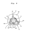
- Fig. 8 is a side, cross sectional view showing a frame in Fig. 7
- Fig. 9 is a front, cross sectional view showing the frame
- Fig. 10 is a view showing an underside of the frame
- Fig. 11 is a side view showing the frame on a side of a speed reducer
- Fig. 12 is a side view showing the frame on a side of a brake.
- the reference numeral 1 denotes a load sheave comprising a chain engagement groove (not shown) and a flange recess (not shown).
- the reference numeral 2 denotes a drive shaft, 2a a fitting section provided on a side of a brake of the drive shaft 2 to permit a brake receiver to be fitted thereinto, and 2b a threaded section, onto which a drive member 30a provided integral with a hand wheel 30 is threaded.
- the reference numeral 3 denotes a reduction gear, 4 a brake receiver, 8 one-way clutch inner race, 8a a pair of brake disks mounted externally with the one-way clutch inner race therebetween, 9 a one-way clutch roller, 10 a roller support ring, and 30 a hand wheel. These elements form drive and brake sections of the hoisting and pulling device.
- the reference numeral 12 denotes an upper hook that suspends a body of the hoisting and pulling device, and 12a a lower hook.
- the reference numeral 13 denotes a frame body.
- the frame body 13 comprises, as shown in Figs. 7 and 9, a drive side frame 13a, a speed reduction side frame 13b, and a connection frame 16 that connects and joins the both frames, the frames 13a, 13b.
- the frames 13a, 13b respectively, have overhangs and on outer peripheral end edges thereof, a drive side cover fitting section 15a and a speed reducer side cover fitting section 15b, onto which a drive side cover 29a and a speed reducer side cover 29b are fitted, are provided.
- the drive side frame 13a comprises a thick wall section 14 extending outward from a bearing section of the load sheave 1.
- a brake receiver bearing hole 18, a brake receiver cover section 18a, a one-way clutch roller joint hole 19, and a roller support ring latch groove 20 are provided successively outward.
- the thick wall section 14 is provided with a molten metal flowing section (introduction section), through which molten metal flows at the time of molding.
- molten metal flowing section introduction section
- molten metal flows directly to the drive side frame 13a from the thick wall section 14 at the time of molding to form the drive side frame, and flows to the speed reduction side frame 13b through the connection frame 16, so that the both frames 13a, 13b and the connection frame 16 can be molded to have desired thicknesses.
- connection frame 16 has a curved section 16a curved outward as shown in Fig. 8.
- the speed reduction side frame 13b comprises a reduction gear bearing hole 26 and a reduction gear accommodating section 28 as shown in Fig. 11.
- connection frame 16 has a load sheave bearing hole 17 on a side of the speed reducer, the load sheave is accommodated in a space surrounded by the connection frame 16 as shown in Fig. 8, and in order to allow passage of a chain 11 inside the connection frame 16, in which the load sheave accommodation space is molded, there are provided a longitudinal link guide groove 22a and a transverse link guide groove 22b inside the longitudinal link guide groove 22a in a crosswise guide groove 22, which is somewhat wider than a link width of the chain. Also, a frame bottom 13c shown in Fig. 10 is formed at a lower end of the connection frame 16 shown in Fig. 8 to be made integral with the connection frame 16.
- the frame bottom 13c comprises a longitudinal link guide hole 23a communicated to the longitudinal link guide groove 22a provided on the connection frame 16, and a transverse link guide hole 23b communicated to the transverse link guide groove 22b, and is further provided as shown in Figs. 7 to 10 with a chain entangling prevention section 21, which projects inward and toward the load sheave 1 from the frame bottom 13c to prevent entangling of the chain in the same manner as in the embodiment 1.
- a cover installation section has a drive side cover fitting section 15a and a speed reducer side cover fitting section 15b, which extend outwardly in an axial direction of the drive shaft of the drive side frame 13a and the speed reduction side frame 13b, respectively, in order to fit and install the drive side cover 29a and the speed reducer side cover 29b.
- the cover fitting sections 15a, 15b are provided with flanges 32 spaced inside by a plate thickness of the drive side cover 29a and the speed reducer side cover 29b from the outer peripheral end edges of the drive side frame 13a and the speed reduction side frame 13b.
- cover installation screw holes 27 into which installation screws (not shown) for fixation of the drive side cover 29a and the speed reducer side cover 29b to the drive side frame 13a and the speed reduction side frame 13b are threaded.
- the installation screw holes 27 are preferably provided near corners 33, and peripheries of the installation screw holes 27 do not define recesses as in the embodiment 1 but are flat to serve as sections for positioning of the drive side cover 29a, the speed reducer side cover 29b, the drive side frame 13a and the speed reduction side frame.
- the speed reduction side frame 13b bears respective one ends of the reduction gear 3 and the drive shaft 2, it is necessary to position and mount the frame to the body frame and positional deviation of the covers is not allowed in use. But positioning is carried out by the cover installation screw holes 27 and the corners 33 of the cover fitting sections 15a, 15b provided close to the holes 27, which are formed by precision casting, whereby it is possible to carry out positioning at the same time of assembling, thus enabling fixing the covers firmly.
- the flanges 32 at both upper and lower ends of the drive side frame 13a and the speed reduction side frame 13b are provided with cover removal grooves 32a, by which the drive side cover 29a and the speed reducer side cover 29b, fitted onto the both frames 13a, 13b, are removed.
- cover removal groove 32a By inserting a tool into the cover removal groove 32a, the both covers 29a, 29b are readily removed from the both frames 13a, 13b.
- the drive side cover fitting section 15a and the speed reducer side fitting section 15b are shorter in length than those of the embodiment 1 illustrated in Fig. 3. With this manner, when the covers 29a, 29b are fitted onto the fitting sections 15a, 15b, manufacturing errors involved in the cover fitting sections and the covers can be absorbed and fitting can be easily carried out even in the case where slight errors are involved.
- an upper hook installation hole 24 for installation of the upper hook 12 are provided in the drive side frame 13a and the speed reduction side frame 13b above a loaded side A of the connection frame 16, and a chain end mount shaft installation hole 25, through which an unloaded side end of a chain wound around the load sheave inside the curved section 16a of the connection frame 16 is mounted to the body frame, are provided on an unloaded side B of the connection frame, the load sheave bearing hole 17 and the reduction gear bearing hole 26, respectively, are provided below and above a line, which connects between the upper hook installation hole 24 and the chain end mount shaft installation hole 25.
- a load line at the time of hoist motion is inclined as shown in Fig. 8 from the vertical direction in the embodiment 1 shown in Fig. 2, so that the chain conducting passage on the loaded side is inclined in the same direction as the load line 34 as shown in Fig. 8.
- the hoisting and pulling device according to the invention can be considerably reduced in the number of parts and man-hour for assembly, and made small in size, and the frame can be thinned, so that there is produced an effect that the body of the hoisting and pulling device can be made lightweight and mounting and dismounting of the covers are made easy.
- the hoisting and pulling device according to the invention can be considerably reduced in the number of parts and man-hour for assembly as compared with conventional devices, and are especially useful as a small-sized hoisting and pulling device.
Applications Claiming Priority (3)
| Application Number | Priority Date | Filing Date | Title |
|---|---|---|---|
| JP2003323110 | 2003-09-16 | ||
| JP2004268177A JP2005112631A (ja) | 2003-09-16 | 2004-09-15 | 巻上牽引機 |
| PCT/JP2004/013985 WO2005026037A1 (ja) | 2003-09-16 | 2004-09-16 | 巻上牽引機 |
Publications (2)
| Publication Number | Publication Date |
|---|---|
| EP1666403A1 true EP1666403A1 (de) | 2006-06-07 |
| EP1666403A4 EP1666403A4 (de) | 2009-06-17 |
Family
ID=34315675
Family Applications (1)
| Application Number | Title | Priority Date | Filing Date |
|---|---|---|---|
| EP04773375A Withdrawn EP1666403A4 (de) | 2003-09-16 | 2004-09-16 | Hebe- und ziehvorrichtung |
Country Status (4)
| Country | Link |
|---|---|
| US (1) | US7441748B2 (de) |
| EP (1) | EP1666403A4 (de) |
| JP (1) | JP2005112631A (de) |
| WO (1) | WO2005026037A1 (de) |
Families Citing this family (8)
| Publication number | Priority date | Publication date | Assignee | Title |
|---|---|---|---|---|
| JP4693506B2 (ja) | 2005-06-03 | 2011-06-01 | 株式会社キトー | 巻上牽引機 |
| GB201007925D0 (en) * | 2010-05-12 | 2010-06-30 | Wilson Keith | Rope grip apparatus |
| JP6027313B2 (ja) * | 2011-11-08 | 2016-11-16 | 株式会社Lixil | 排水栓用玉鎖の固定方法 |
| CN104114474A (zh) * | 2012-07-17 | 2014-10-22 | 株式会社3H | 电动升降机 |
| JP6068857B2 (ja) * | 2012-07-30 | 2017-01-25 | 株式会社キトー | チェーンブロック |
| AU2015260436B2 (en) * | 2014-05-16 | 2017-12-14 | Kito Corporation | Chain block |
| CN107226427A (zh) * | 2017-06-28 | 2017-10-03 | 浙江博雷重型机床制造有限公司 | 一种低重心卷帘起重机 |
| CN113853932B (zh) * | 2021-10-20 | 2022-10-14 | 浡江生态建设集团有限公司 | 一种后排式草坪割草机集草袋悬挂装置 |
Citations (2)
| Publication number | Priority date | Publication date | Assignee | Title |
|---|---|---|---|---|
| DE856202C (de) * | 1949-09-02 | 1952-11-20 | Hebezeugfabrik Puetzer Defries | Kettenhebezeug |
| JPS56165695A (en) * | 1981-04-27 | 1981-12-19 | Nakamoto Tekkosho Kk | Maintenance device for traction hoist |
Family Cites Families (14)
| Publication number | Priority date | Publication date | Assignee | Title |
|---|---|---|---|---|
| JPS5837239B2 (ja) * | 1979-07-09 | 1983-08-15 | 株式会社 東亜機械製作所 | チエンブロツク |
| JPS5939695A (ja) * | 1982-08-25 | 1984-03-05 | 株式会社キト− | 巻上兼牽引装置 |
| JPH0533264Y2 (de) * | 1986-10-07 | 1993-08-24 | ||
| US5125629A (en) * | 1990-08-29 | 1992-06-30 | Vital Kogyo Kabushiki Kaisha | Hand-operated chain block |
| JPH0533264A (ja) | 1991-07-17 | 1993-02-09 | Asahi Chem Ind Co Ltd | 耐塩素性ポリウレタン弾性糸交編布帛 |
| JPH0776078B2 (ja) * | 1991-10-31 | 1995-08-16 | 象印チエンブロック株式会社 | レバー形牽引機 |
| TW303879U (en) * | 1992-08-17 | 1997-04-21 | Hhh Mfg Co Ltd | Chain lever hoist |
| DE4401184C2 (de) * | 1993-02-17 | 1998-10-29 | Vital Chain Block Mfg | Hebezeug |
| JP3016187U (ja) * | 1995-03-24 | 1995-09-26 | 株式会社キトー | レバー式ホイスト |
| US6032928A (en) * | 1997-05-15 | 2000-03-07 | Elephant Chain Block Co., Ltd. | Hand operated chain block having improved hand wheel |
| JP2919810B2 (ja) * | 1997-05-15 | 1999-07-19 | 象印チエンブロック株式会社 | 手動式チェンブロック |
| JPH1160170A (ja) * | 1997-08-21 | 1999-03-02 | Yoshinaga Kikai Kk | 変速機および揚重・回転装置 |
| JP3065038B2 (ja) * | 1998-10-23 | 2000-07-12 | 象印チエンブロック株式会社 | チェーンブロック |
| JP3355484B2 (ja) * | 1998-11-19 | 2002-12-09 | 象印チエンブロック株式会社 | 巻上機 |
-
2004
- 2004-09-15 JP JP2004268177A patent/JP2005112631A/ja active Pending
- 2004-09-16 WO PCT/JP2004/013985 patent/WO2005026037A1/ja active Application Filing
- 2004-09-16 EP EP04773375A patent/EP1666403A4/de not_active Withdrawn
- 2004-09-16 US US10/571,684 patent/US7441748B2/en active Active
Patent Citations (2)
| Publication number | Priority date | Publication date | Assignee | Title |
|---|---|---|---|---|
| DE856202C (de) * | 1949-09-02 | 1952-11-20 | Hebezeugfabrik Puetzer Defries | Kettenhebezeug |
| JPS56165695A (en) * | 1981-04-27 | 1981-12-19 | Nakamoto Tekkosho Kk | Maintenance device for traction hoist |
Non-Patent Citations (1)
| Title |
|---|
| See also references of WO2005026037A1 * |
Also Published As
| Publication number | Publication date |
|---|---|
| JP2005112631A (ja) | 2005-04-28 |
| US20080105858A1 (en) | 2008-05-08 |
| WO2005026037A1 (ja) | 2005-03-24 |
| EP1666403A4 (de) | 2009-06-17 |
| US7441748B2 (en) | 2008-10-28 |
Similar Documents
| Publication | Publication Date | Title |
|---|---|---|
| US7441748B2 (en) | Hoisting and pulling device | |
| JP3253951B1 (ja) | 伝動装置用プラスチック製可動ガイド | |
| EP2185458B1 (de) | Vorrichtung zum betreiben einer fahrstuhltür | |
| US7614610B2 (en) | Hoisting and pulling device | |
| CZ243499A3 (cs) | Lanový výtah | |
| CA2236731C (en) | Hand operated chain block | |
| JPS5935832B2 (ja) | ウインチ | |
| US6007054A (en) | Hand operated chain block having an improved cover | |
| US4468005A (en) | Lever hoist | |
| JPS58207299A (ja) | レバ−式小型巻上兼牽引装置における遊転装置 | |
| JPS58216895A (ja) | レバ−式小型巻上兼牽引装置における遊転装置 | |
| US5271607A (en) | Bearing structure for hoist/traction apparatus | |
| US5799892A (en) | Baitcasting reel with a lowered profile to facilitate palming | |
| CA2374010C (en) | Hoisting/pulling device | |
| KR20110098202A (ko) | 모듈화 체인 호이스트 | |
| CA2236621C (en) | Hand operated chain block | |
| JP2711650B2 (ja) | 手動式チェンブロック | |
| JP2003201082A (ja) | エレベータ用巻上機 | |
| JPS636147Y2 (de) | ||
| JP4558872B2 (ja) | テンショナー等のレバー及びアーム | |
| CN213569288U (zh) | 一种船舶制造用电动单梁悬挂起重机 | |
| JPH02503550A (ja) | タイヤ持上/支持ウインチ用溝車板及びケーブル組立体 | |
| JPH01181698A (ja) | 小型巻上兼牽引装置 | |
| JP2001141003A (ja) | テンショナー等のレバー | |
| CN100424373C (zh) | 缠绕闸 |
Legal Events
| Date | Code | Title | Description |
|---|---|---|---|
| PUAI | Public reference made under article 153(3) epc to a published international application that has entered the european phase |
Free format text: ORIGINAL CODE: 0009012 |
|
| 17P | Request for examination filed |
Effective date: 20060328 |
|
| AK | Designated contracting states |
Kind code of ref document: A1 Designated state(s): DE |
|
| DAX | Request for extension of the european patent (deleted) | ||
| RBV | Designated contracting states (corrected) |
Designated state(s): DE |
|
| A4 | Supplementary search report drawn up and despatched |
Effective date: 20090514 |
|
| RIC1 | Information provided on ipc code assigned before grant |
Ipc: B66D 3/26 20060101ALI20090508BHEP Ipc: B66D 3/16 20060101AFI20050329BHEP |
|
| 17Q | First examination report despatched |
Effective date: 20090924 |
|
| STAA | Information on the status of an ep patent application or granted ep patent |
Free format text: STATUS: THE APPLICATION IS DEEMED TO BE WITHDRAWN |
|
| 18D | Application deemed to be withdrawn |
Effective date: 20100205 |