EP1664541B1 - Drehkolbenmaschine - Google Patents
Drehkolbenmaschine Download PDFInfo
- Publication number
- EP1664541B1 EP1664541B1 EP04786755A EP04786755A EP1664541B1 EP 1664541 B1 EP1664541 B1 EP 1664541B1 EP 04786755 A EP04786755 A EP 04786755A EP 04786755 A EP04786755 A EP 04786755A EP 1664541 B1 EP1664541 B1 EP 1664541B1
- Authority
- EP
- European Patent Office
- Prior art keywords
- housing
- rotary piston
- piston machine
- machine according
- rotors
- Prior art date
- Legal status (The legal status is an assumption and is not a legal conclusion. Google has not performed a legal analysis and makes no representation as to the accuracy of the status listed.)
- Expired - Lifetime
Links
- 230000008859 change Effects 0.000 claims description 4
- 230000007704 transition Effects 0.000 claims description 2
- 239000000446 fuel Substances 0.000 description 12
- 230000008901 benefit Effects 0.000 description 4
- 238000007667 floating Methods 0.000 description 4
- 238000002347 injection Methods 0.000 description 2
- 239000007924 injection Substances 0.000 description 2
- 210000003734 kidney Anatomy 0.000 description 2
- 238000004519 manufacturing process Methods 0.000 description 2
- 238000005299 abrasion Methods 0.000 description 1
- 230000009471 action Effects 0.000 description 1
- 230000015572 biosynthetic process Effects 0.000 description 1
- 210000001520 comb Anatomy 0.000 description 1
- 238000002485 combustion reaction Methods 0.000 description 1
- 238000010276 construction Methods 0.000 description 1
- 230000000694 effects Effects 0.000 description 1
- 230000002349 favourable effect Effects 0.000 description 1
- 230000006872 improvement Effects 0.000 description 1
- 239000007788 liquid Substances 0.000 description 1
- 238000003754 machining Methods 0.000 description 1
- 238000000034 method Methods 0.000 description 1
- 230000008569 process Effects 0.000 description 1
- 238000005086 pumping Methods 0.000 description 1
- 230000009467 reduction Effects 0.000 description 1
- 238000003860 storage Methods 0.000 description 1
Images
Classifications
-
- F—MECHANICAL ENGINEERING; LIGHTING; HEATING; WEAPONS; BLASTING
- F01—MACHINES OR ENGINES IN GENERAL; ENGINE PLANTS IN GENERAL; STEAM ENGINES
- F01C—ROTARY-PISTON OR OSCILLATING-PISTON MACHINES OR ENGINES
- F01C1/00—Rotary-piston machines or engines
- F01C1/08—Rotary-piston machines or engines of intermeshing engagement type, i.e. with engagement of co- operating members similar to that of toothed gearing
- F01C1/082—Details specially related to intermeshing engagement type machines or engines
-
- F—MECHANICAL ENGINEERING; LIGHTING; HEATING; WEAPONS; BLASTING
- F01—MACHINES OR ENGINES IN GENERAL; ENGINE PLANTS IN GENERAL; STEAM ENGINES
- F01C—ROTARY-PISTON OR OSCILLATING-PISTON MACHINES OR ENGINES
- F01C19/00—Sealing arrangements in rotary-piston machines or engines
- F01C19/10—Sealings for working fluids between radially and axially movable parts
-
- F—MECHANICAL ENGINEERING; LIGHTING; HEATING; WEAPONS; BLASTING
- F01—MACHINES OR ENGINES IN GENERAL; ENGINE PLANTS IN GENERAL; STEAM ENGINES
- F01C—ROTARY-PISTON OR OSCILLATING-PISTON MACHINES OR ENGINES
- F01C21/00—Component parts, details or accessories not provided for in groups F01C1/00 - F01C20/00
- F01C21/10—Outer members for co-operation with rotary pistons; Casings
- F01C21/104—Stators; Members defining the outer boundaries of the working chamber
- F01C21/108—Stators; Members defining the outer boundaries of the working chamber with an axial surface, e.g. side plates
-
- F—MECHANICAL ENGINEERING; LIGHTING; HEATING; WEAPONS; BLASTING
- F04—POSITIVE - DISPLACEMENT MACHINES FOR LIQUIDS; PUMPS FOR LIQUIDS OR ELASTIC FLUIDS
- F04C—ROTARY-PISTON, OR OSCILLATING-PISTON, POSITIVE-DISPLACEMENT MACHINES FOR LIQUIDS; ROTARY-PISTON, OR OSCILLATING-PISTON, POSITIVE-DISPLACEMENT PUMPS
- F04C3/00—Rotary-piston machines or pumps, with non-parallel axes of movement of co-operating members, e.g. of screw type
- F04C3/06—Rotary-piston machines or pumps, with non-parallel axes of movement of co-operating members, e.g. of screw type the axes being arranged otherwise than at an angle of 90 degrees
- F04C3/08—Rotary-piston machines or pumps, with non-parallel axes of movement of co-operating members, e.g. of screw type the axes being arranged otherwise than at an angle of 90 degrees of intermeshing engagement type, i.e. with engagement of co-operating members similar to that of toothed gearing
- F04C3/085—Rotary-piston machines or pumps, with non-parallel axes of movement of co-operating members, e.g. of screw type the axes being arranged otherwise than at an angle of 90 degrees of intermeshing engagement type, i.e. with engagement of co-operating members similar to that of toothed gearing the axes of cooperating members being on the same plane
Definitions
- the invention relates to a rotary piston engine according to the preamble of the main claim.
- a rotary engine is known by the US-A 3,236,186 (Wildhaber, Ernest ) of February 22, 1966.
- Fig. 4 a rotary piston machine known as a conveyor unit, with at an axial angle to each other arranged rotors (drive part and driven part) and with a machine housing.
- the working spaces are formed, which are increased or reduced during the rotation of the parts for their work or to produce the conveying effect on a medium.
- Another such rotary engine is known by the DE-PS 4241320 (Arnold, Felix ) as a pump, compressor or motor, in which run the combs of teeth of a rotating drive part to limit work spaces on a cycloid surface of a likewise toothed driven part and thereby driving it.
- the rotary piston engine according to the invention with the characterizing features of claim 1 has the advantage that the invention in particular in the fuel delivery of internal combustion engines, for example as a feed pump in diesel injection systems or as pre-feed pump or as a pressure and supply pump of gasoline injection systems, can serve.
- the combination as a unit, between the motor housing and the machine housing, offers the possibility to make such a delivery or pressure pump small, since the electric motor can attack the output side directly to the drive part of the rotors, without additional complex storage.
- connection of the housing can be given in various ways, for example, as a screw connection between two "pots" on the one hand surround the pump and on the other hand the electric motor, or there may be a Verbörtelung between a cover part and a cup part, depending on how this for the practical use and, above all, a favorable production makes sense.
- Decisive for the invention is that in the motor housing, which are arranged part related to the electric motor, such as the magnets and the bearing of the rotor and that the pump housing are housed in the machine housing, including the inflow and outflow device for the medium.
- Such an "electric pump” according to the invention is not limited in its application as a fuel pump, but can be used depending on the size and performance of liquid or gaseous media, with much higher pressures can be generated than in the known fuel pump (company Robert Bosch GmbH or the like). ,
- the bearing bush is connected to a bottom bearing for the driven part, on which the driven part is supported on its side facing away from the drive part.
- bearing bush and bottom bearing on the same axis, perpendicular to the bearing surface stands, on which the output part is supported.
- the rotors run in an inner housing in which open to the rotors towards the suction channel and the pressure channel are arranged.
- This inner housing is rotatably and not floating within the rest of the machine housing and in particular against rotation of the bottom bearing.
- the inner housing may be arranged in an additional housing bushing and secured there against turning.
- This housing socket in turn, can be stored in the outer machine housing.
- the rotors run in a recess (of the inner housing), which is open and cylindrical to the driven side, and closed to the drive side and formed spherically.
- the drive part can be supported, while the driven part is held on the cylindrical side by the bearing bush and the bottom bearing in its working position.
- the drive part has an inner spherical region on which the drive part with a correspondingly shaped end face, or the bearing bush of the driven part can be supported.
- the driven part is axially loaded in the direction of the drive part.
- the output member is loaded by a spring force in the direction of the drive part.
- a spring force may be particularly advantageous in the starting phase of such a pump in order to achieve the required for the promotion of tightness between the working edges of the intermeshing teeth.
- the pressure channel of the machine is connected to a space between the driven part and the housing (bottom bearing) on the side facing away from the drive part. This ensures that when the medium has reached a certain pressure in the pressure channel, the driven part is pressed against the drive member so that thereby a better tightness between the flanks can be achieved.
- the rotor is mounted with its one shaft in a fixed bearing, which is supported by the inner housing and on which the drive member is axially supportable. It is thus a both as a radial bearing for the engine as a thrust bearing for the drive part, the latter particularly causes a reduction in the friction losses between the drive part and the inner housing.
- the transitions between the mutually facing the axial support serving spherical bearing surfaces and the work space delimiting tooth surfaces are rounded at the rotors.
- the radius of such rounding preferably has at least 1 mm. Basically, this radius depends on the size of the pump parts.
- short-circuit channels or short-circuiting grooves are arranged in the bottom surface of the rotors, via which adjacent work spaces can be connected to one another during rotation and, in particular, before opening a suction or pressure channel, in order to accommodate the changing volumes of the work spaces To achieve pressure equalization.
- the delivery chambers change between the parts, with the associated flanks of the teeth of one part to slide over the corresponding surfaces of the other part, so that the lying between the teeth spaces from which the actual working spaces arise, here act as harmful spaces. While an overpressure would be created in the one harmful room, a negative pressure would be created in the adjacent room.
- the fuel delivery pump shown has a rotary lobe pump 1 and an electric motor 2 driving this, which are arranged in a motor housing 3 and a housing cover 4 screwed onto it.
- the electric motor is greatly simplified represents with a rotor 5 and a magnet ring 6, and an axial closure part 7 of the motor housing 3, which is connected to the motor housing 3 and sealed to this.
- a pivot bearing 8 of the rotor 5, and the pressure port. 9 arranged for the fuel discharge.
- the fuel pump is designed as a submersible pump, in which via suction ports 10, which are only indicated here, the fuel passes into the pump to then leave the pump via the pressure port 9 again.
- the electric motor 5, 6 flows around the fuel within the motor housing 3.
- the second pivot bearing of the rotor 5 is formed as a fixed bearing 11, which is arranged in a corresponding bore on the end face of an inner housing 12 of the rotary lobe pump 1 and on which the drive member 17 can be supported axially.
- This inner housing 12 is arranged outside in a housing bushing 13, which in turn is sealed to the motor housing 3, partially clamped in this and partially within the housing cover 4.
- a recess 14 is provided in the inner housing 12, with a cylindrical portion 15 and a spherical portion sixteenth
- the recess 14 is closed on the output side by a bottom bearing 22, which is arranged obliquely to the axis of the recess 14 in order to achieve the required conveying angle and which is sealed at 23 to the inner housing 12.
- a bearing pin 24 is arranged perpendicular to the recess 14 facing the end face of the bottom bearing 22, on which via a blind bore 25 (FIG. FIG. 3 ) the driven part 18 is mounted.
- the output member 18 is also loaded in the direction of the drive member 17 by a coil spring 26 and a ball 27, wherein the spring is arranged in a blind bore 28 of the journal 24 and the ball is supported on the end face of the blind bore 25.
- the output part 18 is supported via a spherical surface 29 facing the drive part 17 on a corresponding spherical recess 30 on the drive part 17 (FIG. Fig. 3 ).
- FIGS. 4, 5 and 6 is recognizable as the conveying process takes place.
- the work spaces 21 ( FIG. 2 ) are supplied with fuel via conveyor kidneys 31 which are arranged in the walls of the inner housing 12, and disposed of.
- the fuel is then directed to the underside of the driven part 18, whereby this is loaded in the direction of the drive part 17, which, however, only works when the pump has already generated pressure.
Landscapes
- Engineering & Computer Science (AREA)
- Mechanical Engineering (AREA)
- General Engineering & Computer Science (AREA)
- Rotary Pumps (AREA)
- Reciprocating Pumps (AREA)
- Connection Of Motors, Electrical Generators, Mechanical Devices, And The Like (AREA)
- Hydraulic Motors (AREA)
Description
- Die Erfindung geht aus von einer Drehkolbenmaschine nach dem Oberbegriff des Hauptanspruchs. Eine derartige Drehkolbenmaschine ist bekannt durch die
US-A 3,236,186 (Wildhaber, Ernest ) vom 22. Februar 1966. Durch diese Patentschrift ist inFig. 4 eine Drehkolbenmaschine als Fördereinheit bekannt, mit unter einem axialen Winkel zueinander angeordneten Rotoren (Antriebsteil und Abtriebsteil) und mit einem Maschinengehäuse. - Zwischen den Zähnen von Antriebsteil und Abtriebsteil werden die Arbeitsräume gebildet, die während des Rotierens der Teile für ihre Arbeit vergrößert bzw. verkleinert werden, um die Förderwirkung auf ein Medium zu erzeugen.
- Eine andere derartige Drehkolbenmaschine ist bekannt durch die
DE-PS 4241320 (Arnold, Felix - Es ist auch schon vorgeschlagen worden (Patentanmeldung
DE 103 35 939.7 vom 02. August 2003) einen Teil des Maschinengehäuses "schwimmend" zu lagern, um dadurch besser Spaltverluste udgl. ausgleichen zu können. Eine derartige schwimmende Anordnung hat allerdings den Nachteil, dass auf Kosten einer Abnahme der Verluste durch Spalte die Gefahr von Unwuchten entsteht. Die Bedeutung dieses Nachteils hängt vom praktischen Einsatz des Gegenstandes ab, wobei die dann tatsächlich ausgeübte Drehzahl und der angestrebte Druck eine wesentliche Rolle spielen. - Die erfindungsgemäße Drehkolbenmaschine mit den kennzeichnenden Merkmalen des Anspruchs 1 hat demgegenüber den Vorteil, dass die Erfindung insbesondere im Kraftstoffförderwesen von Brennkraftmaschinen, beispielsweise als Vorförderpumpe bei Dieseleinspritzanlagen oder als Vorförderpumpe bzw. als Druck und Zuführpumpe von Benzineinspritzanlagen, dienen kann. Die Kombination als Baueinheit, zwischen Motorgehäuse und Maschinengehäuse, bietet die Möglichkeit eine solche Förder- bzw. Druckpumpe klein zu gestalten, da der Elektromotor abtriebseitig unmittelbar an dem Antriebsteil der Rotoren angreifen kann, ohne zusätzliche aufwendige Lagerung. Die Verbindung der Gehäuse kann in unterschiedlichster Weise gegeben sein, beispielsweise als Schraubverbindung zwischen zwei "Töpfen" die einerseits die Pumpe und andererseits den Elektromotor umgreifen, oder es kann eine Verbörtelung zwischen einem Deckelteil und einem Topfteil gegeben sein, je nach dem wie dies für den praktischen Einsatz und vor allem eine günstige Fertigung sinnvoll erscheint. Maßgebend für die Erfindung ist, dass in dem Motorgehäuse, die den Elektromotor betreffenden Teil angeordnet sind, wie die Magnete sowie die Lagerung des Läufers und dass im Maschinengehäuse die Pumpteile untergebracht sind, einschließlich der Zu- und Abströmeinrichtung für das Medium.
- Um zu dieser Baueinheit zu kommen, musste eine Voreingenommenheit überwunden werden, die insbesondere darin bestand, dass ein Antrieb des Antriebsteils eine Achsjustierung verlangt, über die, wenn auch nur geringe Exzentrizitäten der Achsen von Motor und Antriebsglied korrigiert werden können. Auch das Bemühen, das Antriebsteil schwimmend im Gehäuse anzuordnen, lässt dieses Problem erkennen, insbesondere dann, wenn zwischen der Antriebswelle des Motors und dem als Antriebsteil dienenden Rotor, ein Kraftschluss erwünscht ist. Es sei an dieser Stelle darauf hingewiesen, dass besonders im Fahrzeugbau und dem Einsatz einer Kraftstoffförderpumpe in einem Kraftfahrzeug, ein Minimum an Geräuschentwicklung angestrebt ist. Schon die geringsten Unwuchten würden jedoch zu zum erheblichen Geräuschen führen, was das Problem, das der Erfindung zugrunde liegt, noch stärker verdeutlicht.
- Die beanspruchte Lagerbuchse ist zwar schon früher vorgeschlagen worden, spielt jedoch in Verbindung der einzelnen Merkmale des Anspruchs 1 und deren Ausgestaltungen eine erhebliche Rolle.
- Eine solche erfindungsgemäße "Elektropumpe" ist in ihrer Anwendung nicht eingeschränkt als Kraftstofföderpumpe, sondern kann je nach Größe und Leistung für flüssige oder gasförmige Medien eingesetzt werden, wobei wesentlich höhere Drücke erzeugbar sind als bei den bekannten Kraftstofföderpumpen (Fa. Robert Bosch GmbH odgl.).
- Nach einer vorteilhaften Ausgestaltung der Erfindung ist durch die Verdrehung der Lagerbuchse des Antriebsteils eine Veränderung der Drehlage der Arbeitsräume zu Saug- und Druckkanal und damit zur Arbeitsphase der Arbeitsräume in Bezug auf Saugkanal und Druckkanal vorhanden. Hierdurch ist in einfacher Weise die oben als problematisch dargestellte Justierung gelöst.
- Nach einer zusätzlichen Ausgestaltung der Erfindung, ist die Lagerbuchse mit einem Bodenlager für das Abtriebsteil verbunden, an welchem sich das Abtriebsteil auf seiner dem Antriebsteil abgewandten Seite abstützt. Hierbei weisen Lagerbuchse und Bodenlager die gleiche Achse auf, die senkrecht auf der Lagerfläche steht, auf der sich das Abtriebsteil abstützt. Durch Verdrehen dieses Bodenlagers innerhalb des Maschinengehäuses, erfolgt die oben genannte Relatiwerstellung von Förderbeginn zu Zu- und Abflusskanälen, mit der Folge, einer Veränderung der Förderleistung der Maschine.
- Nach einer zusätzlichen vorteilhaften Ausgestaltung der Erfindung, laufen die Rotoren in einem Innengehäuse, in welchem zu den Rotoren hin offen der Saugkanal und der Druckkanal angeordnet sind. Dieses Innengehäuse ist drehfest und nicht schwimmend innerhalb des übrigen Maschinengehäuses angeordnet und insbesondere gegenüber dem Bodenlager verdrehgesichert. Hierbei kann das Innengehäuse in einer zusätzlichen Gehäusebuchse angeordnet sein und dort gegen Sichverdrehen gesichert sein. Diese Gehäusebuchse wiederum, kann in dem äußeren Maschinengehäuse gelagert sein.
- Nach einer zusätzlichen vorteilhaften Ausgestaltung der Erfindung, laufen die Rotoren in einer Ausnehmung (des Innengehäuses), die zur Abtriebseite hin offen und zylindrisch, und zur Antriebsseite hin geschlossen und sphärisch ausgebildet ist. An dieser sphärischen Fläche kann sich das Antriebsteil abstützen, während das Abtriebsteil auf der zylindrischen Seite durch die Lagerbuchse und das Bodenlager in seiner Arbeitslage gehalten wird.
- Nach einer zusätzlichen vorteilhaften Ausgestaltung der Erfindung weist das Antriebsteil einen inneren sphärischen Bereich auf, an dem sich das Antriebsteil mit einer entsprechend gestalteten Stirnseite, bzw. die Lagerbuchse des Abtriebsteils abstützen kann. Hierdurch wird der ohnehin weniger effektive innere Bereich der Rotoren, nahe der jeweiligen Drehachse, nicht für die Pumpfunktion verwendet, so dass die radial weiter außen liegenden, effektiveren Abschnitte der Rotoren die Arbeitsräume bilden.
- Nach einer zusätzlichen vorteilhaften Ausgestaltung der Erfindung ist das Abtriebsteil in Richtung Antriebsteil axial belastet.
- Nach einer diesbezüglichen vorteilhaften Ausgestaltung der Erfindung, ist das Abtriebsteil durch einer Federkraft in Richtung Antriebsteil belastet. Eine solche Federkraft kann insbesondere in der Startphase einer solchen Pumpe von Vorteil sein, um die für die Förderung erforderliche Dichtheit zwischen den Arbeitsflanken der ineinandergreifenden Zähne zu erreichen.
- Nach einer möglichen zusätzlichen diesbezüglichen Ausgestaltung der Erfindung, ist der Druckkanal der Maschine mit einem Raum zwischen Abtriebsteil und Gehäuse (Bodenlager) auf der dem Antriebsteil abgewandten Seite verbunden. Hierdurch wird erreicht, dass wenn das Medium im Druckkanal einen gewissen Druck erreicht hat, das Abtriebsteil derart gegen das Antriebsteil gepresst wird, dass hierdurch eine bessere Dichtheit zwischen den Flanken erzielbar ist.
- Nach einer zusätzlichen vorteilhaften Ausgestaltung der Erfindung ist der Läufer mit seiner einen Welle in einem Festlager gelagert, welches vom Innengehäuse getragen wird und an dem das Antriebsteils axial abstützbar ist. Es handelt sich somit um ein sowohl als Radiallager für den Motor als Axiallager für das Antriebsteil, wobei Letzteres besonders eine Reduzierung der Reibungsverluste zwischen Antriebsteil und Innengehäuse bewirkt.
- Nach einer zusätzlichen vorteilhaften Ausgestaltung der Erfindung, sind an den Rotoren die Übergänge zwischen den einander zugewandten der axialen Abstützung dienenden sphärischen Auflageflächen und den den Arbeitsraum begrenzenden Zahnflächen abgerundet.
- Durch eine solche Abrundung wird einerseits eine höhere Dichtheit zwischen den Begrenzungen der Arbeitsräume erreicht, was zu einer Verbesserung der effektiven Druck- und Förderwirkung der Pumpe führt und es wird andererseits die Bearbeitung der Pumpenteile in diesen Abschnitten bei der Fertigung vereinfacht, ganz abgesehen davon, dass die bei scharfkantigen Teilen gegebene Gefahr von Spänebildung vermieden wird. Der Radius derartiger Abrundungen weist vorzugsweise mindestens 1 mm auf. Grundsätzlich ist dieser Radius abhängig von der Größe der Pumpenteile.
- Nach einer zusätzlichen Ausgestaltung der Erfindung, sind in der Bodenfläche der Rotoren Kurzschlusskanäle, bzw. Kurzschlussnuten angeordnet, über welche während des Rotierens und insbesondere vor dem Aufsteuern eines Saug- oder Druckkanals benachbarte Arbeitsräume miteinander verbindbar sind, um bei den sich ändernden Volumina der Arbeitsräume einen Druckausgleich zu erzielen. Während des Rotierens von Antriebsteil und Abtriebsteil und vor Aufsteuern des Saugkanals ändern sich die Förderräume zwischen den Teilen, wobei die zugeordneten Flanken der Zähne des einen Teils über die entsprechenden Flächen des anderen Teils gleiten, so dass die zwischen den Zähnen liegenden Räume, aus denen die tatsächlichen Arbeitsräume entstehen, hier als schädliche Räume wirken. Während in dem einen schädlichen Raum ein Überdruck entstehen würde, würde in dem benachbarten Raum ein Unterdruck entstehen. Durch die Erfindung erfolgt ein Druckausgleich der Räume, was dem Pumpenwirkungsgrad zugute kommt.
- Weitere Vorteile und vorteilhafte Ausgestaltung der Erfindung sind der nachfolgenden Beschreibung, der Zeichnung und den Ansprüchen entnehmbar.
- Ein Ausführungsbeispiele des Gegenstandes der Erfindung ist in der Zeichnung dargestellt und im folgenden näher beschrieben. Es zeigen:
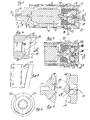
- Fig. 1
- Eine erfindungsgemäße Kraftstoffförderpumpe im Längsschnitt entsprechend dem Pfeil I in
Figur 2 ; - Fig. 2
- Einen Längsschnitt durch einen Teil der Förderpumpe entsprechend der Linie II-II in
Figur 1 ; - Fig. 3
- Die einander zugeordneten Rotoren der Pumpe im Längsschnitt im vergrößerten Maßstab, sowie in Explosionsdarstellung;
- Fig. 4
- Das Innengehäuse der Pumpe im Längsschnitt;
- Fig. 5
- Das Innengehäuse in der radialen Seitenansicht und
- Fig. 6
- Das Innengehäuse in der Axialansicht entsprechend dem Pfeil VI in
Fig. 4 . - Die dargestellte Kraftstoffförderpumpe weist eine Drehkolbenpumpe 1 und einen diese antreibenden Elektromotor 2 auf, die in einem Motorgehäuse 3 und einen darauf aufgeschraubten Gehäusedeckel 4 angeordnet sind. Hierbei ist besonders der Elektromotor stark vereinfacht darstellt mit einem Läufer 5 und einem Magnetring 6, sowie einem axialem Verschlussteil 7 des Motorgehäuses 3, welches mit dem Motorgehäuse 3 verbunden und zu diesem abgedichtet ist. Außerdem sind an diesem Verschlussteil 7 die eine Drehlagerung 8 des Läufers 5, sowie der Druckanschluss 9 für die Kraftstoffableitung angeordnet. Die Kraftstofföderpumpe ist als Tauchpumpe ausgebildet, bei der über Saugöffnungen 10, die hier nur angedeutet sind, der Kraftstoff in die Pumpe gelangt um dann über den Druckanschluss 9 die Pumpe wieder zu verlassen. Hierbei ist der Elektromotor 5, 6 vom Kraftstoff innerhalb des Motorgehäuses 3 umströmt.
- Das zweite Drehlager des Läufers 5 ist als Festlager 11 ausgebildet, welches in einer entsprechenden Bohrung an der Stirnseite eines Innengehäuses 12 der Drehkolbenpumpe 1 angeordnet ist und an dem sich das Antriebsteil 17 axial abstützen kann. Dieses Innengehäuse 12 ist außen in einer Gehäusebuchse 13 angeordnet, die wiederum zum Motorgehäuse 3 hin abgedichtet, teilweise in diesem und teilweise innerhalb des Gehäusedeckels 4 eingespannt ist.
- Wie besonders
Figur 4 entnehmbar ist, ist im Inngehäuse 12 eine Ausnehmung 14 vorgesehen, mit einem zylindrischen Abschnitt 15 und einem sphärischen Abschnitt 16. - In dieser Ausnehmung 14 arbeiten zwei Pumprotoren nämlich ein Antriebsteil 17 und ein Abtriebsteil 18. Das Antriebsteil 17 wird durch die Welle 20 des Elektromotors 2 angetrieben und überträgt seine Drehbewegung auf das Abtriebsteil 18. Auf den Stirnseiten des Antriebsteil 17 und des Abriebsteils 18 sind zykloide Verzahnungen vorgesehen, wie sie in
Figur 3 erkennbar sind, und die entsprechende einander zugewandte Arbeitsflächen 19 aufweisen. Hierdurch werden zwischen den Arbeitsflächen 19 und der Innenwand der Ausnehmung 14 Pumparbeitsräume 21 gebildet, wie es inFigur 2 erkennbar ist. - Die Ausnehmung 14 ist abtriebsseitig durch ein Bodenlager 22 verschlossen, welches zur Achse der Ausnehmung 14 schräg angeordnet ist, um den erforderlichen Förderwinkel zu erzielen und welches bei 23 zum Innengehäuse 12 hin abgedichtet ist. Auf diesem Bodenlager 22 ist ein Lagerzapfen 24 angeordnet und zwar senkrecht zur der Ausnehmung 14 zugewandten Stirnseite des Bodenlagers 22, auf welchem über eine Sackbohrung 25 (
Figur 3 ) das Abtriebsteil 18 gelagert ist. Wie ausFigur 1 und 2 erkennbar ist, wird zudem das Abtriebsteil 18 in Richtung Antriebsteil 17 durch eine Schraubenfeder 26 und eine Kugel 27 belastet, wobei die Feder in einer Sackbohrung 28 des Lagerzapfens 24 angeordnet ist und sich die Kugel an der Stirnseite der Sackbohrung 25 abstützt. Hierdurch wird besonders beim Anlauf der Förderpumpe eine gute Dichtheit zwischen den Arbeitsflächen von Antriebs- und Abtriebsteil erreicht. Außerdem stützt sich das Abtriebsteil 18 über eine dem Antriebsteil 17 zugewandten Kugelfläche 29 an einer entsprechenden sphärischen Ausnehmung 30 am Antriebsteil 17 ab (Fig. 3 ). - In den
Figuren 4, 5 und 6 ist erkennbar wie der Fördervorgang erfolgt. Die Arbeitsräume 21 (Figur 2 ) werden über Fördernieren 31 die in den Wänden des Innengehäuses 12 angeordnet sind, mit Kraftstoff versorgt bzw. entsorgt. Druckseitig wird der Kraftstoff dann auf die Unterseite des Abtriebsteils 18 geleitet, wodurch dieses in Richtung Antriebsteil 17 belastet wird, was allerdings nur funktioniert wenn die Pumpe bereits Druck erzeugt hat. -
- 1
- Drehkolbenpumpe
- 2
- Elektromotor
- 3
- Motorgehäuse
- 4
- Gehäusedeckel
- 5
- Läufer
- 6
- Magnetring
- 7
- Verschlussteil
- 8
- Drehlagerung
- 9
- Druckanschluss
- 10
- Saugöffnungen
- 11
- Festlager
- 12
- Innengehäuse
- 13
- Gehäusebuchse
- 14
- Ausnehmung
- 15
- Zylindrischer Abschnitt
- 16
- sphärischer Abschnitt
- 17
- Antriebsteil
- 18
- Abtriebsteil
- 19
- Arbeitsflächen
- 20
- Welle von 5
- 21
- Pumparbeitsräume
- 22
- Bodenlager
- 23
- Abdichtung
- 24
- Lagerzapfen
- 25
- Sackbohrung
- 26
- Schraubenfeder
- 27
- Kugel
- 28
- Sackbohrung
- 29
- Kugelfläche
- 30
- sphärische Ausnehmung
- 31
- Fördernieren
Claims (14)
- Drehkolbenmaschine (1)- mit mindestens zwei aus Antriebsteil (17) und Abtriebsteil (18) zusammenwirkender Rotoren, die durch stirnseitige Verzahnung (19) Arbeitsräume (21) begrenzen und die unter einem axialen Winkel ihrer Drehachsen zueinander angeordnet sind,- mit einem die Rotoren (17, 18) aufnehmenden Maschinengehäuse (12),- mit Drehlagerung (24, 25) der Rotoren (17, 18) im Maschinengehäuse (12),- mit einer Lagerbuchse (24) des Abtriebsteils (18), die unter entsprechendem axialen Winkel zum Antriebsteil (17) angeordnet ist,- mit einem Saugkanal (31) und einem Druckkanal (31), welche beim Laufen der Rotoren intermittierend mit den Arbeitsräumen verbunden werden und- mit einer Antriebseinrichtung (2) der Maschine,
dadurch gekennzeichnet- dass als Antriebseinrichtung (2) ein in einem Motorgehäuse (3, 7) angeordneter Elektromotor dient, dessen Läufer (5) einerseits im Motorgehäuse (3, 7) und andererseits im Maschinengehäuse (12) achsgleich zum Antriebsteil (17) gelagert ist- dass das Maschinengehäuse (12) und das Motorgehäuse (3) miteinander verbunden sind- dass das Abtriebsteil (18) in Richtung Antriebsteil (17) durch Federkraft oder an einem der Triebteile auf der der Verzahnung abgewandten Seite angreifenden Kraft des zu fördernden Mediums belastet ist. - Drehkolbenmaschine nach Anspruch 1,
dadurch gekennzeichnet,
dass durch Verdrehung der Lagerbuchse (24) des Abtriebsteils (18) eine Veränderung der Drehlage der Arbeitsräume (21) zu Saug- und Druckkanal (31) und damit zur Arbeitsphase der Arbeitsräume in Bezug auf Saugkanal und Druckkanal vorhanden ist. - Drehkolbenmaschine nach Anspruch 1 oder 2,
dadurch gekennzeichnet,
dass die Lagerbuchse (24) mit einem Bodenlager (22) für das Abtriebsteil (18) verbunden ist, an welchem sich das Abtriebsteil (18) auf seiner dem Antriebsteil (17) abgewandten Seite abstützt. - Drehkolbenmaschine nach einem der vorhandenen Ansprüche 1 oder 2
dadurch gekennzeichnet,
dass die Rotoren (17, 18) in einem Innengehäuse (12) des Maschinengehäuses laufen, in welchem zu den Rotoren hin offen der Saugkanal (31) und der Druckkanal (31) angeordnet sind. - Drehkolbenmaschine nach Anspruch 4,
dadurch gekennzeichnet,
dass das Innengehäuse (12) in einer Gehäusebuchse (13) angeordnet und gegen Sichverdrehen gesichert ist. - Drehkolbenmaschine nach einem der vorhergehenden Ansprüche,
dadurch gekennzeichnet,
dass die Rotoren (17, 18) in einer Ausnehmung (14) des Innengehäuses(12) laufen, die zur Abtriebsseite hin offen und zylindrisch (Abschnitt 15) und zur Antriebsseite hin sphärisch (Abschnitt 16) geschlossen ausgebildet ist. - Drehkolbenmaschine nach einem der vorhergehenden Ansprüche,
dadurch gekennzeichnet,
dass das Antriebsteil (17) einen inneren sphärischen Bereich (30) aufweist an dem sich das Abtriebsteil bzw. die Lagerbuchse des Abtriebsteils (18) mit einer entsprechend gestalteten Stirnseite (29) abstützen kann. - Drehkolbenmaschine nach einem der vorhergehenden Ansprüche,
dadurch gekennzeichnet,
dass das Abtriebsteil in Richtung Antriebsteil (17) axial belastbar ist. - Drehkolbenmaschine nach Anspruch 7,
dadurch gekennzeichnet,
dass das Abtriebsteil (18) durch eine Federkraft (26) in Richtung Antriebsteil (17) belastet ist. - Drehkolbenmaschine nach Anspruch 8 oder 9,
dadurch gekennzeichnet,
dass der Druckkanal (31) der Maschine mit einem Raum zwischen Abtriebsteil (18) und Gehäuse bzw. Bodenlager (22) auf der dem Antriebsteil (18) abgewandten Seite verbunden ist. - Drehkolbenmaschine nach einem der vorhergehenden Ansprüche,
dadurch gekennzeichnet,
dass der Läufer (5) mit seiner einen Welle (20) in einem Festlager (11) gelagert ist, welches im Innengehäuse (12) getragen wird und an dem das Antriebsteil (17) axial abstützbar ist. - Drehkolbenmaschine nach einem der vorhergehenden Ansprüche,
dadurch gekennzeichnet,
dass an den Rotoren (17, 18) die Übergänge zwischen den einander zugewandten der axialen Abstützung dienenden sphärischen Auflageflächen (29, 30) und den den Arbeitsraum (21) begrenzenden Zahnflächen, abgerundet sind. - Drehkolbenmaschine nach Anspruch 12,
dadurch gekennzeichnet,
dass die Abrundung einen Radius von mindestens 1 mm aufweist. - Drehkolbenmaschine nach einem der vorhergehenden Ansprüche,
dadurch gekennzeichnet,
dass in den Bodenflächen der Rotoren (17, 18) Kurzschlusskanäle, bzw. Kurzschlussnuten angeordnet sind, über die während des Rotierens und insbesondere vor Aufsteuern eines Saug- oder Druckkanals benachbarte Arbeitsräume (21) miteinander verbindbar sind, um bei den sich ändernden Volumina der Arbeitsräume (21) einen Druckausgleich zu erzielen.
Priority Applications (1)
| Application Number | Priority Date | Filing Date | Title |
|---|---|---|---|
| PL04786755T PL1664541T3 (pl) | 2003-09-11 | 2004-09-10 | Maszyna z tłokiem obrotowym |
Applications Claiming Priority (2)
| Application Number | Priority Date | Filing Date | Title |
|---|---|---|---|
| DE10342341 | 2003-09-11 | ||
| PCT/DE2004/002034 WO2005024237A1 (de) | 2003-09-11 | 2004-09-10 | Drehkolbenmaschine |
Publications (2)
| Publication Number | Publication Date |
|---|---|
| EP1664541A1 EP1664541A1 (de) | 2006-06-07 |
| EP1664541B1 true EP1664541B1 (de) | 2012-03-14 |
Family
ID=34258649
Family Applications (1)
| Application Number | Title | Priority Date | Filing Date |
|---|---|---|---|
| EP04786755A Expired - Lifetime EP1664541B1 (de) | 2003-09-11 | 2004-09-10 | Drehkolbenmaschine |
Country Status (10)
| Country | Link |
|---|---|
| US (1) | US7390181B2 (de) |
| EP (1) | EP1664541B1 (de) |
| JP (1) | JP5053637B2 (de) |
| AT (1) | ATE549516T1 (de) |
| BR (1) | BRPI0414231B1 (de) |
| CA (1) | CA2536279C (de) |
| DE (1) | DE102004044297A1 (de) |
| ES (1) | ES2381002T3 (de) |
| PL (1) | PL1664541T3 (de) |
| WO (1) | WO2005024237A1 (de) |
Families Citing this family (12)
| Publication number | Priority date | Publication date | Assignee | Title |
|---|---|---|---|---|
| DE102004026048A1 (de) * | 2004-05-25 | 2005-12-29 | Cor Pumps + Compressors Ag | Spaltverluststromsteuerung |
| US8834140B2 (en) | 2004-05-25 | 2014-09-16 | Cor Pumps + Compressors Ag | Leakage loss flow control and associated media flow delivery assembly |
| JP5085528B2 (ja) * | 2005-03-16 | 2012-11-28 | ローベルト ボツシユ ゲゼルシヤフト ミツト ベシユレンクテル ハフツング | 回転ピストン機械 |
| EP2016287B1 (de) * | 2006-05-10 | 2018-07-11 | Robert Bosch GmbH | Drehkolbenmaschine |
| DE102007033659A1 (de) * | 2007-07-17 | 2009-01-22 | Cor Pumps + Compressors Ag | Stirnzahnradumwälzpumpe |
| US8517707B2 (en) * | 2007-08-31 | 2013-08-27 | Robert Bosch Gmbh | Method for converting energy from compressed air into mechanical energy and compressed air motor therefor |
| DE102008003240B4 (de) | 2008-01-04 | 2024-02-15 | Robert Bosch Gmbh | Förderaggregat |
| DE102008038625A1 (de) * | 2008-08-12 | 2010-02-18 | Cor Pumps + Compressors Ag | Stirnzahnradpumpe |
| DE102009006521A1 (de) | 2009-01-28 | 2010-07-29 | Cor Pumps + Compressors Ag | Drehkolbenmaschine |
| JP5671754B1 (ja) * | 2013-03-05 | 2015-02-18 | 有限会社中▲野▼製作所 | 回転駆動装置 |
| DE102014209140A1 (de) * | 2013-05-23 | 2014-11-27 | Robert Bosch Gmbh | Förderaggregat |
| DE102014219219A1 (de) * | 2014-09-24 | 2016-03-24 | Robert Bosch Gmbh | Förderaggregat |
Family Cites Families (15)
| Publication number | Priority date | Publication date | Assignee | Title |
|---|---|---|---|---|
| US2662482A (en) * | 1951-09-12 | 1953-12-15 | Paulsmeier Fritz | Ball piston pump |
| US2831436A (en) * | 1952-08-19 | 1958-04-22 | Garvenswerke Maschinen Pumpen & Waagenfabrik W Garvens | Pump |
| US3101700A (en) * | 1960-06-14 | 1963-08-27 | Meredith E Bowdish | Rotary compressor or engine |
| US3236186A (en) | 1963-04-29 | 1966-02-22 | Wildhaber Ernest | Positive-displacement unit |
| DE1551081A1 (de) | 1967-06-06 | 1970-04-16 | Walter Bietzig | Drehkugelmaschine |
| CH571647A5 (de) * | 1973-11-09 | 1976-01-15 | Inventa Ag | |
| DE2913608C2 (de) * | 1979-04-02 | 1982-10-14 | Wolfhart Dipl.-Phys. 8037 Olching Willimczik | Drehkolbenartige Rotationskolbenmaschine |
| US4981424A (en) * | 1988-12-21 | 1991-01-01 | The United States Of America As Represented By The Secretary Of The Navy | High pressure single screw compressors |
| DE4241320C2 (de) | 1991-12-09 | 2002-01-17 | Arnold Felix | Drehkolbenmaschine |
| CA2215219C (en) * | 1996-11-19 | 2000-07-04 | Yukio Kajino | Disc-type rotary engine |
| DE10035900A1 (de) * | 2000-07-21 | 2002-01-31 | Bosch Gmbh Robert | Innenzahnradpumpe |
| JP2002364572A (ja) * | 2001-06-07 | 2002-12-18 | Kawakami Seisakusho:Kk | 流体圧送装置 |
| DE10150653A1 (de) * | 2001-10-13 | 2003-04-30 | Bosch Gmbh Robert | Innenzahnradpumpe |
| JP3964200B2 (ja) * | 2001-12-26 | 2007-08-22 | 愛三工業株式会社 | 燃料ポンプ |
| JP4473122B2 (ja) | 2002-08-02 | 2010-06-02 | コア・ポンプス・プルス・コンプレッサーズ・アクチエンゲゼルシャフト | 変位可能な内部ケーシングから成る回転ピストン機械 |
-
2004
- 2004-09-10 EP EP04786755A patent/EP1664541B1/de not_active Expired - Lifetime
- 2004-09-10 DE DE102004044297A patent/DE102004044297A1/de not_active Ceased
- 2004-09-10 AT AT04786755T patent/ATE549516T1/de active
- 2004-09-10 BR BRPI0414231-4A patent/BRPI0414231B1/pt not_active IP Right Cessation
- 2004-09-10 JP JP2006525623A patent/JP5053637B2/ja not_active Expired - Lifetime
- 2004-09-10 PL PL04786755T patent/PL1664541T3/pl unknown
- 2004-09-10 WO PCT/DE2004/002034 patent/WO2005024237A1/de not_active Ceased
- 2004-09-10 CA CA2536279A patent/CA2536279C/en not_active Expired - Fee Related
- 2004-09-10 ES ES04786755T patent/ES2381002T3/es not_active Expired - Lifetime
- 2004-09-10 US US10/571,244 patent/US7390181B2/en not_active Expired - Lifetime
Also Published As
| Publication number | Publication date |
|---|---|
| CA2536279C (en) | 2013-02-12 |
| BRPI0414231A (pt) | 2006-10-31 |
| PL1664541T3 (pl) | 2012-08-31 |
| JP5053637B2 (ja) | 2012-10-17 |
| JP2007505250A (ja) | 2007-03-08 |
| EP1664541A1 (de) | 2006-06-07 |
| WO2005024237A1 (de) | 2005-03-17 |
| ES2381002T3 (es) | 2012-05-22 |
| DE102004044297A1 (de) | 2005-05-04 |
| US20060263228A1 (en) | 2006-11-23 |
| BRPI0414231B1 (pt) | 2013-03-19 |
| ATE549516T1 (de) | 2012-03-15 |
| US7390181B2 (en) | 2008-06-24 |
| CA2536279A1 (en) | 2005-03-17 |
Similar Documents
| Publication | Publication Date | Title |
|---|---|---|
| EP1664541B1 (de) | Drehkolbenmaschine | |
| EP1664540B1 (de) | Drehkolbenmaschine | |
| DE68920225T2 (de) | Hydraulischer Drehimpuls-Generator für Schraubenschlüssel. | |
| DE102004026048A1 (de) | Spaltverluststromsteuerung | |
| DE19513822C2 (de) | Einrichtung zum Fördern von Kraftstoff aus einem Vorratstank zu einer Brennkraftmaschine eines Kraftfahrzeuges | |
| EP2391827B1 (de) | Drehkolbenmaschine mit einen aussenläufer elektromotor. | |
| EP1859170B1 (de) | Drehkolbenmaschine | |
| DE102008038625A1 (de) | Stirnzahnradpumpe | |
| DE4428410C2 (de) | Kompakte Regeleinheit für eine Flügelzellenpumpe | |
| DE3804842C2 (de) | ||
| DE10349752B4 (de) | Motorpumpenaggregat | |
| EP2655801B1 (de) | Drehkolbenmaschine, die als pumpe, verdichter oder motor arbeitet | |
| DE2533776A1 (de) | Drehmotor | |
| DE102012206797A1 (de) | Drehkolbenmaschine, die als Pumpe, Verdichter oder Motor für ein Fluid wirkt | |
| WO2010072478A2 (de) | Innenzahnradpumpe | |
| DE202004004231U1 (de) | Volumenstromveränderbare Verdrängerpumpe | |
| DE102006025367B4 (de) | Zahnradpumpe, insbesondere Zahnradölpumpe für Fahrzeuge | |
| EP2005001A1 (de) | Zellenpumpe | |
| DE720794C (de) | Gasturbinenanlage mit Gleichdruckverbrennung und einem von der Turbine angetriebenen Verdichter | |
| DE102010063532A1 (de) | Pumpe, Verdichter oder Motor mit kleinem Durchmesser-Längenverhältnis | |
| DE9006632U1 (de) | Zahnrad-Kraftstoffpumpe | |
| EP2655803B1 (de) | Pumpe, verdichter oder motor mehrstufig oder mehrflutig | |
| DE4318737C2 (de) | Drehkolbenkompressor | |
| DE3929745A1 (de) | Fluegelzellenkompressor | |
| DE202021102758U1 (de) | Rotationspumpe zum Fördern eines Fluids |
Legal Events
| Date | Code | Title | Description |
|---|---|---|---|
| PUAI | Public reference made under article 153(3) epc to a published international application that has entered the european phase |
Free format text: ORIGINAL CODE: 0009012 |
|
| 17P | Request for examination filed |
Effective date: 20060126 |
|
| AK | Designated contracting states |
Kind code of ref document: A1 Designated state(s): AT BE BG CH CY CZ DE DK EE ES FI FR GB GR HU IE IT LI LU MC NL PL PT RO SE SI SK TR |
|
| 17Q | First examination report despatched |
Effective date: 20060929 |
|
| DAX | Request for extension of the european patent (deleted) | ||
| RAP1 | Party data changed (applicant data changed or rights of an application transferred) |
Owner name: ROBERT BOSCH GMBH |
|
| GRAP | Despatch of communication of intention to grant a patent |
Free format text: ORIGINAL CODE: EPIDOSNIGR1 |
|
| RAP1 | Party data changed (applicant data changed or rights of an application transferred) |
Owner name: ROBERT BOSCH GMBH |
|
| GRAS | Grant fee paid |
Free format text: ORIGINAL CODE: EPIDOSNIGR3 |
|
| GRAA | (expected) grant |
Free format text: ORIGINAL CODE: 0009210 |
|
| AK | Designated contracting states |
Kind code of ref document: B1 Designated state(s): AT BE BG CH CY CZ DE DK EE ES FI FR GB GR HU IE IT LI LU MC NL PL PT RO SE SI SK TR |
|
| REG | Reference to a national code |
Ref country code: GB Ref legal event code: FG4D Free format text: NOT ENGLISH |
|
| REG | Reference to a national code |
Ref country code: AT Ref legal event code: REF Ref document number: 549516 Country of ref document: AT Kind code of ref document: T Effective date: 20120315 Ref country code: CH Ref legal event code: EP |
|
| REG | Reference to a national code |
Ref country code: IE Ref legal event code: FG4D Free format text: LANGUAGE OF EP DOCUMENT: GERMAN |
|
| REG | Reference to a national code |
Ref country code: DE Ref legal event code: R096 Ref document number: 502004013371 Country of ref document: DE Effective date: 20120510 |
|
| REG | Reference to a national code |
Ref country code: ES Ref legal event code: FG2A Ref document number: 2381002 Country of ref document: ES Kind code of ref document: T3 Effective date: 20120522 |
|
| REG | Reference to a national code |
Ref country code: NL Ref legal event code: VDEP Effective date: 20120314 |
|
| PG25 | Lapsed in a contracting state [announced via postgrant information from national office to epo] |
Ref country code: GR Free format text: LAPSE BECAUSE OF FAILURE TO SUBMIT A TRANSLATION OF THE DESCRIPTION OR TO PAY THE FEE WITHIN THE PRESCRIBED TIME-LIMIT Effective date: 20120615 Ref country code: FI Free format text: LAPSE BECAUSE OF FAILURE TO SUBMIT A TRANSLATION OF THE DESCRIPTION OR TO PAY THE FEE WITHIN THE PRESCRIBED TIME-LIMIT Effective date: 20120314 |
|
| REG | Reference to a national code |
Ref country code: PL Ref legal event code: T3 |
|
| PG25 | Lapsed in a contracting state [announced via postgrant information from national office to epo] |
Ref country code: CY Free format text: LAPSE BECAUSE OF FAILURE TO SUBMIT A TRANSLATION OF THE DESCRIPTION OR TO PAY THE FEE WITHIN THE PRESCRIBED TIME-LIMIT Effective date: 20120314 |
|
| PG25 | Lapsed in a contracting state [announced via postgrant information from national office to epo] |
Ref country code: CZ Free format text: LAPSE BECAUSE OF FAILURE TO SUBMIT A TRANSLATION OF THE DESCRIPTION OR TO PAY THE FEE WITHIN THE PRESCRIBED TIME-LIMIT Effective date: 20120314 Ref country code: SE Free format text: LAPSE BECAUSE OF FAILURE TO SUBMIT A TRANSLATION OF THE DESCRIPTION OR TO PAY THE FEE WITHIN THE PRESCRIBED TIME-LIMIT Effective date: 20120314 Ref country code: RO Free format text: LAPSE BECAUSE OF FAILURE TO SUBMIT A TRANSLATION OF THE DESCRIPTION OR TO PAY THE FEE WITHIN THE PRESCRIBED TIME-LIMIT Effective date: 20120314 Ref country code: SI Free format text: LAPSE BECAUSE OF FAILURE TO SUBMIT A TRANSLATION OF THE DESCRIPTION OR TO PAY THE FEE WITHIN THE PRESCRIBED TIME-LIMIT Effective date: 20120314 Ref country code: EE Free format text: LAPSE BECAUSE OF FAILURE TO SUBMIT A TRANSLATION OF THE DESCRIPTION OR TO PAY THE FEE WITHIN THE PRESCRIBED TIME-LIMIT Effective date: 20120314 |
|
| REG | Reference to a national code |
Ref country code: HU Ref legal event code: AG4A Ref document number: E014254 Country of ref document: HU |
|
| PG25 | Lapsed in a contracting state [announced via postgrant information from national office to epo] |
Ref country code: PT Free format text: LAPSE BECAUSE OF FAILURE TO SUBMIT A TRANSLATION OF THE DESCRIPTION OR TO PAY THE FEE WITHIN THE PRESCRIBED TIME-LIMIT Effective date: 20120716 Ref country code: SK Free format text: LAPSE BECAUSE OF FAILURE TO SUBMIT A TRANSLATION OF THE DESCRIPTION OR TO PAY THE FEE WITHIN THE PRESCRIBED TIME-LIMIT Effective date: 20120314 |
|
| PLBE | No opposition filed within time limit |
Free format text: ORIGINAL CODE: 0009261 |
|
| STAA | Information on the status of an ep patent application or granted ep patent |
Free format text: STATUS: NO OPPOSITION FILED WITHIN TIME LIMIT |
|
| PG25 | Lapsed in a contracting state [announced via postgrant information from national office to epo] |
Ref country code: NL Free format text: LAPSE BECAUSE OF FAILURE TO SUBMIT A TRANSLATION OF THE DESCRIPTION OR TO PAY THE FEE WITHIN THE PRESCRIBED TIME-LIMIT Effective date: 20120314 Ref country code: DK Free format text: LAPSE BECAUSE OF FAILURE TO SUBMIT A TRANSLATION OF THE DESCRIPTION OR TO PAY THE FEE WITHIN THE PRESCRIBED TIME-LIMIT Effective date: 20120314 |
|
| 26N | No opposition filed |
Effective date: 20121217 |
|
| BERE | Be: lapsed |
Owner name: ROBERT BOSCH G.M.B.H. Effective date: 20120930 |
|
| REG | Reference to a national code |
Ref country code: DE Ref legal event code: R097 Ref document number: 502004013371 Country of ref document: DE Effective date: 20121217 |
|
| PG25 | Lapsed in a contracting state [announced via postgrant information from national office to epo] |
Ref country code: MC Free format text: LAPSE BECAUSE OF NON-PAYMENT OF DUE FEES Effective date: 20120930 |
|
| REG | Reference to a national code |
Ref country code: CH Ref legal event code: PL |
|
| REG | Reference to a national code |
Ref country code: IE Ref legal event code: MM4A |
|
| PG25 | Lapsed in a contracting state [announced via postgrant information from national office to epo] |
Ref country code: BG Free format text: LAPSE BECAUSE OF FAILURE TO SUBMIT A TRANSLATION OF THE DESCRIPTION OR TO PAY THE FEE WITHIN THE PRESCRIBED TIME-LIMIT Effective date: 20120614 Ref country code: CH Free format text: LAPSE BECAUSE OF NON-PAYMENT OF DUE FEES Effective date: 20120930 Ref country code: BE Free format text: LAPSE BECAUSE OF NON-PAYMENT OF DUE FEES Effective date: 20120930 Ref country code: IE Free format text: LAPSE BECAUSE OF NON-PAYMENT OF DUE FEES Effective date: 20120910 Ref country code: LI Free format text: LAPSE BECAUSE OF NON-PAYMENT OF DUE FEES Effective date: 20120930 |
|
| REG | Reference to a national code |
Ref country code: AT Ref legal event code: MM01 Ref document number: 549516 Country of ref document: AT Kind code of ref document: T Effective date: 20120910 |
|
| PG25 | Lapsed in a contracting state [announced via postgrant information from national office to epo] |
Ref country code: AT Free format text: LAPSE BECAUSE OF NON-PAYMENT OF DUE FEES Effective date: 20120910 |
|
| PG25 | Lapsed in a contracting state [announced via postgrant information from national office to epo] |
Ref country code: TR Free format text: LAPSE BECAUSE OF FAILURE TO SUBMIT A TRANSLATION OF THE DESCRIPTION OR TO PAY THE FEE WITHIN THE PRESCRIBED TIME-LIMIT Effective date: 20120314 |
|
| PG25 | Lapsed in a contracting state [announced via postgrant information from national office to epo] |
Ref country code: LU Free format text: LAPSE BECAUSE OF NON-PAYMENT OF DUE FEES Effective date: 20120910 |
|
| REG | Reference to a national code |
Ref country code: FR Ref legal event code: PLFP Year of fee payment: 13 |
|
| REG | Reference to a national code |
Ref country code: FR Ref legal event code: PLFP Year of fee payment: 14 |
|
| REG | Reference to a national code |
Ref country code: FR Ref legal event code: PLFP Year of fee payment: 15 |
|
| PGFP | Annual fee paid to national office [announced via postgrant information from national office to epo] |
Ref country code: IT Payment date: 20190920 Year of fee payment: 16 |
|
| PGFP | Annual fee paid to national office [announced via postgrant information from national office to epo] |
Ref country code: ES Payment date: 20191023 Year of fee payment: 16 |
|
| PGFP | Annual fee paid to national office [announced via postgrant information from national office to epo] |
Ref country code: HU Payment date: 20200913 Year of fee payment: 17 Ref country code: PL Payment date: 20200901 Year of fee payment: 17 |
|
| PG25 | Lapsed in a contracting state [announced via postgrant information from national office to epo] |
Ref country code: IT Free format text: LAPSE BECAUSE OF NON-PAYMENT OF DUE FEES Effective date: 20200910 |
|
| REG | Reference to a national code |
Ref country code: ES Ref legal event code: FD2A Effective date: 20220117 |
|
| PG25 | Lapsed in a contracting state [announced via postgrant information from national office to epo] |
Ref country code: ES Free format text: LAPSE BECAUSE OF NON-PAYMENT OF DUE FEES Effective date: 20200911 |
|
| PG25 | Lapsed in a contracting state [announced via postgrant information from national office to epo] |
Ref country code: HU Free format text: LAPSE BECAUSE OF NON-PAYMENT OF DUE FEES Effective date: 20210911 |
|
| PG25 | Lapsed in a contracting state [announced via postgrant information from national office to epo] |
Ref country code: PL Free format text: LAPSE BECAUSE OF NON-PAYMENT OF DUE FEES Effective date: 20210910 |
|
| PGFP | Annual fee paid to national office [announced via postgrant information from national office to epo] |
Ref country code: GB Payment date: 20230921 Year of fee payment: 20 |
|
| PGFP | Annual fee paid to national office [announced via postgrant information from national office to epo] |
Ref country code: FR Payment date: 20230918 Year of fee payment: 20 |
|
| PGFP | Annual fee paid to national office [announced via postgrant information from national office to epo] |
Ref country code: DE Payment date: 20231124 Year of fee payment: 20 |
|
| REG | Reference to a national code |
Ref country code: DE Ref legal event code: R071 Ref document number: 502004013371 Country of ref document: DE |
|
| REG | Reference to a national code |
Ref country code: GB Ref legal event code: PE20 Expiry date: 20240909 |
|
| PG25 | Lapsed in a contracting state [announced via postgrant information from national office to epo] |
Ref country code: GB Free format text: LAPSE BECAUSE OF EXPIRATION OF PROTECTION Effective date: 20240909 |
|
| PG25 | Lapsed in a contracting state [announced via postgrant information from national office to epo] |
Ref country code: GB Free format text: LAPSE BECAUSE OF EXPIRATION OF PROTECTION Effective date: 20240909 |