EP1663588B1 - Grundplatte für ein elektrowerkzeug und verfahren zur herstellung derselben - Google Patents
Grundplatte für ein elektrowerkzeug und verfahren zur herstellung derselben Download PDFInfo
- Publication number
- EP1663588B1 EP1663588B1 EP04762385.5A EP04762385A EP1663588B1 EP 1663588 B1 EP1663588 B1 EP 1663588B1 EP 04762385 A EP04762385 A EP 04762385A EP 1663588 B1 EP1663588 B1 EP 1663588B1
- Authority
- EP
- European Patent Office
- Prior art keywords
- base plate
- metal sheet
- plate according
- material thickness
- piece
- Prior art date
- Legal status (The legal status is an assumption and is not a legal conclusion. Google has not performed a legal analysis and makes no representation as to the accuracy of the status listed.)
- Expired - Lifetime
Links
Images

Classifications
-
- B—PERFORMING OPERATIONS; TRANSPORTING
- B27—WORKING OR PRESERVING WOOD OR SIMILAR MATERIAL; NAILING OR STAPLING MACHINES IN GENERAL
- B27B—SAWS FOR WOOD OR SIMILAR MATERIAL; COMPONENTS OR ACCESSORIES THEREFOR
- B27B9/00—Portable power-driven circular saws for manual operation
- B27B9/02—Arrangements for adjusting the cutting depth or the amount of tilting
-
- B—PERFORMING OPERATIONS; TRANSPORTING
- B23—MACHINE TOOLS; METAL-WORKING NOT OTHERWISE PROVIDED FOR
- B23D—PLANING; SLOTTING; SHEARING; BROACHING; SAWING; FILING; SCRAPING; LIKE OPERATIONS FOR WORKING METAL BY REMOVING MATERIAL, NOT OTHERWISE PROVIDED FOR
- B23D47/00—Sawing machines or sawing devices working with circular saw blades, characterised only by constructional features of particular parts
- B23D47/02—Sawing machines or sawing devices working with circular saw blades, characterised only by constructional features of particular parts of frames; of guiding arrangements for work-table or saw-carrier
-
- B—PERFORMING OPERATIONS; TRANSPORTING
- B23—MACHINE TOOLS; METAL-WORKING NOT OTHERWISE PROVIDED FOR
- B23D—PLANING; SLOTTING; SHEARING; BROACHING; SAWING; FILING; SCRAPING; LIKE OPERATIONS FOR WORKING METAL BY REMOVING MATERIAL, NOT OTHERWISE PROVIDED FOR
- B23D51/00—Sawing machines or sawing devices working with straight blades, characterised only by constructional features of particular parts; Carrying or attaching means for tools, covered by this subclass, which are connected to a carrier at both ends
- B23D51/02—Sawing machines or sawing devices working with straight blades, characterised only by constructional features of particular parts; Carrying or attaching means for tools, covered by this subclass, which are connected to a carrier at both ends of beds; of guiding arrangements for work-tables or saw carriers; of frames
Definitions
- the invention is based on a base plate for a power tool with the generic features of claim 1.
- a base plate is the EP 0 990 492 refer to.
- base plates for hand-held circular, jigsaws, Mauemut- and routers which are designed as a flat component with low height. These serve to guide the power tool on a workpiece.
- base plates for hand-held circular, jigsaws, Mauemut- and routers are known, which are designed as a flat component with low height. These serve to guide the power tool on a workpiece.
- base plates are known, which are made of sheet steel as a stamped and bent part. They typically have longitudinal beads and a circumferential collar, which serve to increase the stiffness, since the sheet thicknesses are only between 1.5 and 2.5 mm. Such components are inexpensive to manufacture, since among other things, technical functions, such as recording a rip fence or pivot points for the angular adjustment, are made possible by parts that can be formed directly from the sheet without a subsequent processing is necessary. In addition, bent base plates can also be bent back. However, such base plates have the disadvantage that they have a high weight.
- punched parts made of light metal which have no circumferential collar.
- sheet thicknesses of 5 to 6 mm are used.
- superstructures are needed.
- Such a base plate can also be bent back in a bending and has a low weight.
- such a base plate is expensive to manufacture, since it must be equipped with bodies.
- a base plate for a power tool consisting of a metal sheet, which is produced in the stamping-bending process and having a circumferential collar.
- a recess for receiving a saw blade is introduced, wherein the recess is bounded by an inner, openwork collar.
- a first pivoting guide means is arranged, which axially opposite a second pivot guide means is assigned to the base plate, wherein the pivot guide means allow the connection to the housing of the power tool and define a common pivot axis.
- the pivot guide means are each constructed in several parts and, in addition to integrally formed with the base plate parts and separate fasteners.
- a base plate according to the invention for a power tool with the features of claim 1 has the advantage over that by the use of a sheet of light metal and a one-piece design of the base plate, a favorable production can be achieved, the base plate only a small weight with a high rigidity has and can be bent back in a bending and beyond does not break in a shock load. According to the invention, such a base plate is produced by a stamping and bending process.
- the material thickness of the sheet is less than 4 mm, in particular 3 mm, a particularly light and yet sufficient rigidity having base plate is obtained. It is particularly advantageous to use a sheet of an aluminum alloy.
- At least one stiffening element is designed as a circumferential collar
- a base plate with a particularly high rigidity is obtained at a low weight.
- a particularly good rigidity is obtained when the circumferential collar preferably has at least a height of twice the material thickness of the sheet.
- At least one stiffening element is preferably formed as a transverse, diagonal or longitudinal bead, the rigidity of the base plate is further increased.
- a preferably one-piece design of warts and a threaded dome for guiding and positioning a rip fence which is designed in one piece with the base plate, no structures on the base plate for attaching a parallel stopper are required.
- a one-piece design of connecting elements for an angular adjustment of a saw blade with the base plate also no additional structures for the pivoting of the cutting plane are needed.
- a preferably one-piece design of a guide channel with the base plate the power tool can be placed on a guide rail without superstructures are necessary for the realization.
- the connecting elements have bores, by which a rotation axis for the angular displacement of a saw blade is defined, even the elements are integrally attached to the base plate, which are necessary to change the angle of a saw blade, without further structures would be needed. Thus, a cost-effective production of the base plate is given.
- FIG. 1 is a power tool 13 shown in the form of a hand-held circular saw.
- the power tool 13 has a base plate 1 according to the invention, on which a motor is mounted in a motor housing 3.
- the motor drives a saw blade 19, which is arranged under a protective hood 2.
- the power tool 13 is moved by means of a handle 4.
- On the base plate 1 an adjustable rip fence 5 is arranged.
- the saw blade 19 is connected to the base plate 1 in such a way that it can be moved between a plane perpendicular to the base plate 1 and a saw plane pivoted at an angle.
- a connecting element 18 is arranged on the base plate 1, which has a bore 11 for receiving the pivot axis (not shown) and a pivoting gate 16.
- In the pivoting gate 16 an indirectly connected to the saw blade 19 pin is performed, which can be fixed in its position within the pivoting gate 16 by means of a thumb screw 20.
- the aforementioned structure of the power tool 13 is known in principle from the prior art.
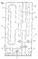
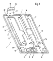
- the features of the base plate 1 according to the invention are best based on FIGS. 2 and 3 and are described below.
- the base plate 1 is made in one piece from a metal sheet of light metal by means of a punch-bending process. Unlike a punching method thus a three-dimensional shape of the base plate 1 is achieved.
- the illustrated base plate 1 consists of an aluminum alloy with a material thickness 15 of 3 mm. Such a base plate 1 has a comparable bending strength as from a 2 mm thick sheet steel. However, due to the significantly lower density of the aluminum alloy compared to that of steel - despite the material thickness increase - about a halving of the weight has been achieved.
- the good rigidity of the base plate 1 according to the invention is achieved by a peripheral collar 6.
- the circumferential collar 6 has a height 17 which is at least twice the material thickness 15 of the sheet metal. It is about 6.5 mm on the inside and 9 mm on the outside.
- two longitudinal beads 7 are formed parallel to the orientation of the saw blade 19. This achieves rigidity which is within the range of alternative embodiments.
- two connecting elements 18 are integrally formed on the base plate 1. These are both vertically above the plane of the base plate 1 out.
- One of the two connecting elements 18 is a part of the further collar 21, the other connecting element 18 is a part of the circumferential collar 6.
- Each of the two connecting elements 18 has a bore 11 in which the pivot axis is mounted, which is indirectly connected to the saw blade 19 is and defines the cutting plane of the circular saw.
- On the connecting element 18, which is a part of the circumferential collar 6, is adjacent to the bore 11 still a pivoting gate 16 is formed, whose function already above based on the Fig. 1 was executed.
- the circumferential collar 6 is formed on its longitudinal sides, which means parallel to the saw blade 19, in each case as a stop surface 12. This makes it possible in a simple manner, the power tool 13 to lead along a bar or similar straight object.
- a threaded dome 9 is present, which receives a thumbscrew (not shown) and clamps the rip fence in position.
- a plurality of warts 8 are formed on the base plate 1. Both the threaded dome 9 and the warts 8 are in this case formed integrally with the base plate 1.
- connection elements 14 is integrally formed in the base plate 1.
- the basic connection of the base plate 1 with the miter angle 23 is well known from the prior art and will not be further described below, since it is not essential to the invention.
- the base plate 1 according to the invention which is produced according to the invention by a stamped-bending process, the advantages of the known base plate designs, namely as stamped and bent part of sheet steel, as a stamped part made of light metal and as a casting of a light metal alloy be achieved without taking over the disadvantages of the three parts mentioned.
- the base plate 1 according to the invention has a significantly reduced weight with comparable rigidity.
- the base plate 1 according to the invention has a significantly lower material thickness 15.
- the material thickness 15 is 3 mm, whereas for stampings typically material thicknesses 15 greater 5 mm are necessary.
- This large material thickness 15 is necessary to obtain the lateral stop surface 12, which is given here by the circumferential collar 6.
- the height 17 of the stop surface is equal to the material thickness 15.
- the base plate 1 according to the invention made of a light metal alloy, which was produced by means of the stamping-bending process, on the other hand, equipped with stiffening elements that do not make the entire base plate 1 with a higher material thickness 15 equipped.
- the lateral abutment surfaces 12 can be adjusted to the desired height 17 regardless of the material thickness 15. The necessary material thickness 15 can thus be reduced with the same functionality compared to the stamped parts, resulting in a weight and cost savings.
- a light metal castings can be used as a base plate, which has a receiving geometry for the rip fence, however, this is a machining rework of the casting necessary. Accordingly, a base plate 1 according to the invention, which was produced by the stamping and bending process is cheaper, since no subsequent processing is necessary. In addition, the base plate 1 according to the invention over a casting has the advantage that it has a higher ductility. A cast metal is more brittle than a metal suitable for forming processes. When impacted, this means that the casting breaks much more easily than a part made from a rolled sheet. The base plate 1 of the invention can be bent back after a fall and a bend again and is still usable. In contrast, a casting tends to break when dropped. The weight reduction achieved by the light metal casting is likewise achieved by a base plate 1 according to the invention, so that the casting has no advantage over this.
Landscapes
- Engineering & Computer Science (AREA)
- Mechanical Engineering (AREA)
- Life Sciences & Earth Sciences (AREA)
- Wood Science & Technology (AREA)
- Forests & Forestry (AREA)
- Sawing (AREA)
- Bending Of Plates, Rods, And Pipes (AREA)
Description
- Die Erfindung geht aus von einer Grundplatte für ein Elektrowerkzeug mit den gattungsbildenden Merkmalen des Anspruchs 1. Eine solche Grundplatte ist der
EP 0 990 492 zu entnehmen. - Es sind Grundplatten für handgeführte Kreis-, Stichsägen, Mauemut- und Oberfräsen bekannt, die als flächiges Bauteil mit geringer Bauhöhe ausgebildet sind. Diese dienen zur Führung des Elektrowerkzeugs auf einem Werkstück. Prinzipiell gibt es drei Ausführungsformen der Grundplatten.
- Zum Ersten sind Grundplatten bekannt, die aus Stahlblech als ein Stanz-Biegeteil ausgeführt sind. Sie weisen typischerweise Längssicken und einen umlaufenden Kragen auf, die zur Erhöhung der Steifheit dienen, da die Blechstärken lediglich zwischen 1,5 und 2,5 mm liegen. Solche Bauteile sind günstig herzustellen, da unter anderem technische Funktionen, wie Aufnahme eines Parallelanschlags oder Drehpunkte für die Winkeleinstellung, durch Teile ermöglicht werden, die direkt aus dem Blech geformt werden können, ohne dass eine nachträgliche Bearbeitung nötig ist. Darüber hinaus können verbogene Grundplatten auch wieder zurückgebogen werden. Allerdings haben solche Grundplatten den Nachteil, dass sie ein hohes Gewicht haben.
- Zum Zweiten sind Stanzteile aus Leichtmetall bekannt, die keinen umlaufenden Kragen haben. Um eine ausreichende Steifigkeit zu erzielen, werden Blechdicken von 5 bis 6 mm verwendet. Zur Herstellung der technischen Funktionen werden allerdings Aufbauten benötigt. Eine solche Grundplatte kann bei einer Verbiegung ebenfalls zurückgebogen werden und weist ein geringes Gewicht auf. Allerdings ist eine solche Grundplatte teuer in der Herstellung, da sie mit Aufbauten bestückt werden muss.
- Zum Dritten sind Gussteile aus Leichtmetall-Legierungen bekannt, die zwar ein sehr geringes Gewicht und eine hohe Steifigkeit aufweisen. Allerdings ist die Herstellung dieser Grundplatten mit sehr hohen Kosten verbunden, da sie nachbearbeitet werden müssen. Darüber hinaus neigen solche Gussteile bei einer Schlagbelastung zum Brechen.
- Aus der
EP 0 990 492 A2 ist eine Grundplatte für ein Elektrowerkzeug bekannt, bestehend aus einem Blech, welches im Stanz-Biege-Verfahren hergestellt ist und einen umlaufenden Kragen aufweist. In die Grundplatte ist eine Ausnehmung zur Aufnahme eines Sägeblattes eingebracht, wobei die Ausnehmung von einem inneren, durchbrochenen Kragen begrenzt ist. - Im Bereich einer Stirnseite der Grundplatte ist ein erstes Schwenk-Führungsmittel angeordnet, dem axial gegenüberliegend ein zweites Schwenk-Führungsmittel an der Grundplatte zugeordnet ist, wobei die Schwenk-Führungsmittel die Anbindung an das Gehäuse des Elektrowerkzeugs ermöglichen und eine gemeinsame Schwenkachse definieren. Die Schwenk-Führungsmittel sind jeweils mehrteilig aufgebaut und umfassen zusätzlich zu einteilig mit der Grundplatte ausgebildeten Teilen auch separate Befestigungsmittel.
- Eine erfindungsgemäße Grundplatte für ein Elektrowerkzeug mit den Merkmalen des Anspruchs 1 hat dem gegenüber den Vorteil, dass durch die Verwendung eines Blechs aus Leichtmetall und eine einstückige Ausbildung der Grundplatte eine günstige Fertigung erzielt werden kann, wobei die Grundplatte nur ein geringes Gewicht bei einer hohen Steifigkeit aufweist sowie bei einer Verbiegung wieder zurückgebogen werden kann und darüber hinaus bei einer Schlagbelastung nicht bricht. Erfindungsgemäß wird eine solche Grundplatte durch ein Stanz-Biege-Verfahren hergestellt.
- Dadurch, dass die Materialstärke des Blechs kleiner als 4 mm, insbesondere 3 mm, ist, wird eine besonders leichte und trotzdem eine ausreichende Steifigkeit aufweisende Grundplatte erhalten. Besonders vorteilhaft ist es dabei, ein Blech aus einer Aluminiumlegierung zu verwenden.
- Dadurch, dass zumindest ein Versteifungselement als ein umlaufender Kragen ausgebildet ist, wird eine Grundplatte mit besonders hoher Steifigkeit bei einem geringen Gewicht erhalten. Eine besonders gute Steifigkeit erhält man dabei, wenn der umlaufende Kragen vorzugsweise mindestens eine Höhe der zweifachen Materialstärke des Blechs aufweist.
- Dadurch, dass zumindest ein Versteifungselement vorzugsweise als eine Quer-, Diagonal- oder Längssicke ausgebildet ist, wird die Steifigkeit der Grundplatte noch weiter erhöht.
- Durch eine vorzugsweise einstückige Ausbildung von Warzen und einen Gewindedom zur Führung und Positionierung eines Parallelanschlags, der einstückig mit der Grundplatte ausgeführt ist, sind keine Aufbauten auf der Grundplatte zur Anbringung eines parallelen Anschlags nötig. Bei einer einstückigen Ausbildung von Verbindungselementen für eine Winkelverstellung eines Sägeblattes mit der Grundplatte sind ebenfalls keine zusätzlichen Aufbauten für die Verschwenkung der Schnittebene nötig. Durch eine vorzugsweise einstückige Ausbildung eines Führungskanals mit der Grundplatte kann das Elektrowerkzeug auf eine Führungsschiene aufgesetzt werden, ohne dass Aufbauten zur Realisierung nötig sind. Durch die drei vorgenannten Maßnahmen wird jeweils eine Reduzierung der Herstellungskosten der Grundplatte erzielt, was insbesondere bei einer Kombination der drei Maßnahmen zu einem erheblichen Sparpotenzial führt.
- Dadurch, dass die Verbindungselemente Bohrungen aufweisen, durch die eine Drehachse für die Winkelverstellung eines Sägeblattes definiert wird, sind schon die Elemente einstückig an der Grundplatte angebracht, die nötig sind, um den Winkel eines Sägeblattes ändern zu können, ohne dass weitere Aufbauten benötigt würden. Somit ist eine kostengünstige Herstellung der Grundplatte gegeben.
- Weitere vorteilhafte Ausgestaltungen der Erfindung sind Gegenstand der Unteransprüche.
- Ein Ausführungsbeispiel der Erfindung ist in der nachstehenden Beschreibung an Hand der zugehörigen Zeichnung näher erläutert.
- Die Figuren zeigen:
- Figur 1
- eine räumliche Darstellung einer Handkreissäge,
- Figur 2
- Draufsicht auf eine erfindungsgemäße Grundplatte (um 180 ° gegenüber der in
Fig. 1 gedreht) und - Figur 3
- eine räumliche Darstellung der in
Fig. 2 dargestellten erfindungsgemäßen Grundplatte. - In
Figur 1 ist ein Elektrowerkzeug 13 in Form einer handgeführten Kreissäge dargestellt. Das Elektrowerkzeug 13 weist eine erfindungsgemäße Grundplatte 1 auf, auf der ein Motor in einem Motorgehäuse 3 befestigt ist. Der Motor treibt ein Sägeblatt 19 an, das unter einer Schutzhaube 2 angeordnet ist. Das Elektrowerkzeug 13 wird mittels eines Handgriffs 4 bewegt. An der Grundplatte 1 ist ein verstellbarer Parallelanschlag 5 angeordnet. Das Sägeblatt 19 ist so mit der Grundplatte 1 verbunden, dass es zwischen einer zur Grundplatte 1 senkrechten Ebene und einer um einen Winkel verschwenkten Sägeebene bewegt werden kann. Dazu ist an der Grundplatte 1 ein Verbindungselement 18 angeordnet, welches eine Bohrung 11 zur Aufnahme der Schwenkachse (nicht dargestellt) und eine Schwenkkulisse 16 aufweist. In der Schwenkkulisse 16 wird ein mit dem Sägeblatt 19 mittelbar verbundener Stift geführt, der in seiner Position innerhalb der Schwenkkulisse 16 mittels einer Flügelschraube 20 festgelegt werden kann. Der vorgenannte Aufbau des Elektrowerkzeugs 13 ist prinzipiell aus dem Stand der Technik bekannt. - Die erfindungsgemäßen Merkmale der Grundplatte 1 sind am besten anhand der
Figuren 2 und 3 zu erkennen und werden im Folgenden beschrieben. - Die Grundplatte 1 ist einstückig aus einem Blech aus Leichtmetall mittels eines Stanz-Biege-Verfahrens hergestellt. Anders als bei einem Stanzverfahren wird somit eine dreidimensionale Form der Grundplatte 1 erreicht. Die dargestellte Grundplatte 1 besteht aus einer Aluminiumlegierung mit einer Materialstärke 15 von 3 mm. Eine solche Grundplatte 1 weist eine vergleichbare Biegefestigkeit auf wie aus einem 2 mm dicken Stahlblech. Allerdings ist aufgrund der bedeutend geringeren Dichte der Aluminiumlegierung gegenüber derjenigen von Stahl - trotz der Materialstärkenerhöhung - ca. eine Halbierung des Gewichts erreicht worden.
- Die gute Steifigkeit der erfindungsgemäßen Grundplatte 1 wird durch einen umlaufenden Kragen 6 erreicht. Der umlaufende Kragen 6 weist eine Höhe 17 auf, die bei gut dem zweifachen der Materialstärke 15 des Blechs liegt. Sie beträgt ca. 6,5 mm an der Innenseite und 9 mm an der Außenseite. Zur weiteren Erhöhung der Steifigkeit der Grundplatte 1 sind parallel zur Ausrichtung des Sägeblatts 19 zwei Längssicken 7 ausgebildet. Dadurch wird eine Steifigkeit erreicht, die im Bereich von alternativen Ausführungsformen liegt.
- Darüber hinaus wird die Steifigkeit noch durch einen weiteren Kragen 21 erhöht, der eine Ausnehmung 22 für das Sägeblatt 19 begrenzt.
- Zur Aufnahme einer Vorrichtung, die das Sägeblatt 19 führt, sind zwei Verbindungselemente 18 einstückig an der Grundplatte 1 ausgebildet. Diese stehen beide senkrecht über die Ebene der Grundplatte 1 heraus. Eine der beiden Verbindungselemente 18 ist ein Teil des weiteren Kragens 21, das andere Verbindungselement 18 ist ein Teil des umlaufenden Kragens 6. Jedes der beiden Verbindungselemente 18 weist eine Bohrung 11 auf, in der die Schwenkachse gelagert ist, die mittelbar mit dem Sägeblatt 19 verbunden ist und die Schnittebene der Kreissäge festlegt. An dem Verbindungselement 18, welches ein Teil des umlaufenden Kragen 6 ist, ist neben der Bohrung 11 noch eine Schwenkkulisse 16 ausgebildet, deren Funktion schon oben anhand der
Fig. 1 ausgeführt wurde. - Der umlaufende Kragen 6 ist an seinen Längsseiten, das bedeutet parallel zum Sägeblatt 19, jeweils als eine Anschlagfläche 12 ausgebildet. Dadurch ist es in einfacher Art und Weise möglich, das Elektrowerkzeug 13 entlang einer Latte oder eines ähnlichen geraden Gegenstandes zu führen.
- Um den Parallelanschlag 5 an der Grundplatte 1 in unterschiedlichen Positionen festlegen zu können, ist ein Gewindedom 9 vorhanden, der eine Flügelschraube (nicht gezeigt) aufnimmt und den Parallelanschlag in seiner Position festklemmt. Um eine saubere parallele Führung des Parallelanschlags 5 zu erreichen, sind an der Grundplatte 1 mehrere Warzen 8 ausgebildet. Sowohl der Gewindedom 9 als auch die Warzen 8 sind hierbei einstückig mit der Grundplatte 1 ausgebildet.
- Zur Verbindung der Grundplatte 1 mit dem Gehrungswinkel 23 ist eine Reihe von Anbindungselementen 14 einstückig in der Grundplatte 1 ausgebildet. Die prinzipielle Verbindung der Grundplatte 1 mit dem Gehrungswinkel 23 ist aus dem Stand der Technik wohl bekannt und wird im Weiteren nicht näher beschrieben, da sie nicht erfindungswesentlich ist.
- Die obigen Ausführungen zur Materialstärke 15 des Blechs und der Höhe 17 des umlaufenden Kragens 6 sind lediglich exemplarisch. Für den Fachmann ist klar, dass auch andere Werte Verwendung finden können, ohne dass der Erfindungsgedanke darauf nicht mehr anzuwenden wäre.
- Zusammenfassend kann gesagt werden, dass durch die erfindungsgemäße Grundplatte 1, die erfindungsgemäß durch ein Stanz-Biege-Verfahren hergestellt wird, die Vorteile der bekannten Grundplattenausführungen, nämlich als Stanz-Biegeteil aus Stahlblech, als Stanzteil aus Leichtmetall und als Gussteil aus einer Leichtmetall-Legierung, erzielt werden, ohne die Nachteile der drei genannten Teile zu übernehmen.
- Gegenüber dem Stanz-Biegeteil aus Stahlblech weist die erfindungsgemäße Grundplatte 1 ein deutlich reduziertes Gewicht bei vergleichbarer Steifigkeit auf. Gegenüber den Stanzteilen, die aufgrund des Stanzprozesses lediglich zweidimensional gestaltet werden können, weist die erfindungsgemäße Grundplatte 1 eine deutlich geringere Materialstärke 15 auf. Im vorliegenden Fall liegt die Materialstärke 15 bei 3 mm, wohingegen für Stanzteile typischerweise Materialstärken 15 größer 5 mm nötig sind. Diese große Materialstärke 15 ist nötig, um die seitliche Anschlagfläche 12, die hier durch den umlaufenden Kragen 6 gegeben ist, zu erhalten. Bei dem Stanzteil ist die Höhe 17 der Anschlagfläche gleich der Materialstärke 15. Darüber hinaus ist es bei den bekannten Stanzteilen nötig, zusätzliche Aufbauten für die Aufnahmegeometrie des Parallelanschlags 5 sowie für die Winkelverstellung des Sägeblattes 19 vorzusehen. Dies führt zum Einen zu einem größeren Materialverbrauch und somit höherem Gewicht und zum Anderen zu einer mit höheren Kosten verbundenen Fertigung des Stanzteils. Die erfindungsgemäße Grundplatte 1 aus einer Leichtmetall-Legierung, die mittels des Stanz-Biege-Verfahrens hergestellt wurde, ist dagegen mit Aussteifungselementen, die nicht die gesamte Grundplatte 1 mit einer höheren Materialstärke 15 erforderlich machen, ausgestattet. Auch die seitlichen Anschlagflächen 12 können unabhängig von der Materialstärke 15 auf die gewünschte Höhe 17 eingestellt werden. Die notwendige Materialstärke 15 kann somit bei gleicher Funktionalität gegenüber den Stanzteilen reduziert werden, woraus sich eine Gewichts- und Kostenersparnis ergibt.
- Zwar kann ein Leichtmetallgussteile als Grundplatte verwendet werden, das eine Aufnahmegeometrie für den Parallelanschlag aufweist, allerdings ist hierfür eine spanende Nacharbeit des Gussteils notwendig. Demnach ist eine erfindungsgemäße Grundplatte 1, die nach dem Stanz-Biege-Verfahren hergestellt wurde preiswerter, da keine nachträgliche Bearbeitung notwendig ist. Darüber hinaus hat die erfindungsgemäße Grundplatte 1 gegenüber einem Gussteil den Vorteil, dass sie eine höhere Duktilität aufweist. Ein gegossenes Metall ist spröder als ein für Umformprozesse geeignetes Metall. Bei Schlagbeanspruchung bedeutet dies, dass das Gussteil deutlich leichter bricht als ein aus einem gewalzten Blech hergestelltes Teil. Die erfindungsgemäße Grundplatte 1 kann nach einem Sturz und einer Verbiegung wieder zurückgebogen werden und ist weiterhin verwendungsfähig. Dem gegenüber neigt ein Gussteil beim Herunterfallen zum Brechen. Die durch das Leichtmetallgussteil erzielte Reduktion des Gewichts wird durch eine erfindungsgemäße Grundplatte 1 ebenso erreicht, so dass das Gussteil gegenüber dieser keinen Vorteil besitzt.
-
- 1
- Grundplatte
- 2
- Schutzhaube
- 3
- Motorgehäuse
- 4
- Handgriff
- 5
- Parallelanschlag
- 6
- umlaufender Kragen
- 7
- Längssicke
- 8
- Warze
- 9
- Gewindedom
- 10
- Führungskanal
- 11
- Bohrung
- 12
- Anschlagfläche
- 13
- Elektrowerkzeug
- 14
- Anbindungselement
- 15
- Materialstärke
- 16
- Schwenkkulisse
- 17
- Höhe des umlaufenden Kragens
- 18
- Verbindungselement
- 19
- Sägeblatt
- 20
- Flügelschraube
- 21
- weiterer Kragen
- 22
- Ausnehmung
- 23
- Gehrungswinkel
Claims (8)
- Grundplatte (1) für ein Elektrowerkzeug (13), insbesondere für handgeführte Kreissägen, Stichsägen, Mauernut- und Oberfräsen, aus einem Blech, mit aus der Ebene des Blechs herausragenden Versteifungselementen, wovon mindestens eines als seitliche Anschlagfläche (12) ausgebildet ist, und mit aus der Ebene des Blechs herausragenden Anbindungselementen (14) zur Befestigung der Grundplatte (1) an dem Gehrungswinkel (23), wobei die gesamte Grundplatte (1) einstückig ausgebildet und im Stanz-Biege-Verfahren hergestellt ist, und wobei Verbindungselemente (18) für eine Winkelverstellung einstückig mit der Grundplatte (1) ausgebildet sind, mit einem umlaufenden Kragen (6) an der Grundplatte (1) und mit einem weiteren Kragen (21), der eine Ausnehmung (22) für das Sägeblatt (19) begrenzt, wobei ein Verbindungselement (18) Teil des umlaufenden Kragens (6) ist und eine Schwenkkulisse (16) aufweist, dadurch gekennzeichnet, dass das Blech aus Leichtmetall besteht, dass die Materialstärke (15) des Blechs kleiner als 4 mm ist und dass die Verbindungselemente (18) Bohrungen (11) aufweisen, durch die eine Drehachse für die Winkelverstellung eines Sägeblattes (19) definiert wird, und dass das andere Verbindungselement (18) Teil des weiteren, die Ausnehmung (22) begrenzenden Kragens (21) ist.
- Grundplatte nach Anspruch 1, dadurch gekennzeichnet, dass die Materialstärke (15) des Blechs 3 mm ist.
- Grundplatte nach Anspruch 1 oder 2, dadurch gekennzeichnet, dass das Blech aus einer Leichtmetalllegierung besteht.
- Grundplatte nach Anspruch 3, dadurch gekennzeichnet, dass das Blech aus einer Aluminium- oder Magnesiumlegierung besteht.
- Grundplatte nach einem der vorstehenden Ansprüche, dadurch gekennzeichnet, dass der umlaufende Kragen (6) mindestens eine Höhe (17) der zweifachen Materialstärke (15) des Blechs hat.
- Grundplatte nach einem der vorstehenden Ansprüche, dadurch gekennzeichnet, dass zumindest ein Versteifungselement als eine Quer-, Diagonal- oder Längssicke (7) ausgebildet ist.
- Grundplatte nach einem der vorstehenden Ansprüche, dadurch gekennzeichnet, dass Warzen (8) und ein Gewindedom (9) zur Führung und Positionierung eines Parallelanschlags (5) einstückig mit der Grundplatte (1) ausgebildet sind.
- Grundplatte nach einem der vorstehenden Ansprüche, dadurch gekennzeichnet, dass ein Führungskanal (10) einstückig mit der Grundplatte (1) ausgebildet ist.
Applications Claiming Priority (2)
| Application Number | Priority Date | Filing Date | Title |
|---|---|---|---|
| DE10342154A DE10342154A1 (de) | 2003-09-12 | 2003-09-12 | Grundplatte für ein Elektrowerkzeug und Verfahren zur Herstellung derselben |
| PCT/DE2004/001525 WO2005025821A1 (de) | 2003-09-12 | 2004-07-14 | Grundplatte für ein electrowerkzeug und verfahren zur herstellung derselben |
Publications (2)
| Publication Number | Publication Date |
|---|---|
| EP1663588A1 EP1663588A1 (de) | 2006-06-07 |
| EP1663588B1 true EP1663588B1 (de) | 2014-01-01 |
Family
ID=34258602
Family Applications (1)
| Application Number | Title | Priority Date | Filing Date |
|---|---|---|---|
| EP04762385.5A Expired - Lifetime EP1663588B1 (de) | 2003-09-12 | 2004-07-14 | Grundplatte für ein elektrowerkzeug und verfahren zur herstellung derselben |
Country Status (5)
| Country | Link |
|---|---|
| US (1) | US20060162171A1 (de) |
| EP (1) | EP1663588B1 (de) |
| CN (1) | CN1849204B (de) |
| DE (1) | DE10342154A1 (de) |
| WO (1) | WO2005025821A1 (de) |
Families Citing this family (12)
| Publication number | Priority date | Publication date | Assignee | Title |
|---|---|---|---|---|
| GB0607171D0 (en) * | 2006-04-10 | 2006-05-17 | Gmca Pty Ltd | Improvements to cutting tools |
| US8209872B1 (en) * | 2007-05-09 | 2012-07-03 | Woodman Tools, Llc | Rolling plate assembly attachment for portable power cutting tools including an improved structural design and manufactured out of improved materials, an improved wheel configuration, and an adjustable bevel gear and a cutting guide |
| US7958641B1 (en) * | 2007-05-09 | 2011-06-14 | Woodman Tools, Llc | Rolling plate assembly attachment for portable power cutting tools including an improved structural design and manufactured out of improved materials, an improved wheel configuration, and an adjustable bevel gear and a cutting guide |
| USD603238S1 (en) * | 2008-08-27 | 2009-11-03 | David Adam Lawrence | Circular saw rip guide system |
| US9089941B2 (en) | 2011-09-30 | 2015-07-28 | Robert Bosch Gmbh | Circular saw guard system |
| USD694606S1 (en) | 2012-08-22 | 2013-12-03 | Robert Bosch Gmbh | Right angle attachment for a rotary hand tool |
| CN104014868B (zh) * | 2013-03-01 | 2017-09-26 | 博世电动工具(中国)有限公司 | 圆锯 |
| JP6342283B2 (ja) * | 2014-09-30 | 2018-06-13 | 京セラインダストリアルツールズ株式会社 | 切断機 |
| WO2018123366A1 (ja) * | 2016-12-28 | 2018-07-05 | 工機ホールディングス株式会社 | 携帯用切断機 |
| US11130252B2 (en) * | 2018-04-02 | 2021-09-28 | Circsaw Technologies Llc | Rolling plate assembly attachment for portable power cutting tools including an improved structural design, improved wheel configuration, and a cutting guide |
| US10875109B1 (en) | 2018-04-30 | 2020-12-29 | Kreg Enterprises, Inc. | Adaptive cutting system |
| US11628587B2 (en) | 2021-02-24 | 2023-04-18 | Techtronic Cordless Gp | Floor saw with blade guard |
Citations (1)
| Publication number | Priority date | Publication date | Assignee | Title |
|---|---|---|---|---|
| EP1428636A1 (de) * | 2002-12-10 | 2004-06-16 | Makita Corporation | Schneidwerkzeug |
Family Cites Families (32)
| Publication number | Priority date | Publication date | Assignee | Title |
|---|---|---|---|---|
| US1854510A (en) * | 1929-11-06 | 1932-04-19 | Walt Products Corp De | Portable power driven saw |
| JPS6040202A (ja) * | 1983-08-13 | 1985-03-02 | 松下電工株式会社 | 電動丸鋸 |
| USD326399S (en) * | 1989-06-26 | 1992-05-26 | Makita Electric Works, Ltd. | Portable electric circular saw |
| USD327828S (en) * | 1990-02-07 | 1992-07-14 | Ryobi Motor Products Corp. | Circular saw or the like |
| USD332735S (en) * | 1990-05-31 | 1993-01-26 | Makita Electric Works, Ltd. | Portable electric circular saw |
| US5010651A (en) * | 1990-07-10 | 1991-04-30 | Skil Corporation | Portable circular saw |
| USD334523S (en) * | 1990-08-17 | 1993-04-06 | Ryobi Motor Products | Circular saw |
| DE4124233A1 (de) * | 1991-07-22 | 1993-01-28 | Bosch Gmbh Robert | Handkreissaege |
| DE4322303A1 (de) * | 1993-07-05 | 1995-01-12 | Bosch Gmbh Robert | Handwerkzeugmaschine |
| USD370162S (en) * | 1993-12-17 | 1996-05-28 | Ryobi Motor Products Corp. | Circular saw |
| DE4403189B4 (de) * | 1994-02-02 | 2006-01-12 | Robert Bosch Gmbh | Handkreissäge mit Pendelschutzhaube und mit einer Schnittiefen-Einstellvorrichtung |
| USD363656S (en) * | 1994-08-02 | 1995-10-31 | Black & Decker Inc. | Cordless circular saw |
| USD375439S (en) * | 1994-12-27 | 1996-11-12 | Makita Corporation | Cordless circular saw |
| US5819420A (en) * | 1997-04-08 | 1998-10-13 | Collins; David A. | Coping foot for a jig saw and method of use |
| US5758425A (en) * | 1997-05-20 | 1998-06-02 | S-B Power Tool Company | Depth-of-cut mechanism for circular saw |
| USD408248S (en) * | 1998-02-06 | 1999-04-20 | Black & Decker Inc. | Circular saw |
| DE19844807A1 (de) * | 1998-09-30 | 2000-04-13 | Bosch Gmbh Robert | Motorgetriebene Handwerkzeugmaschine für Trennarbeiten, insbesondere Handkreissäge |
| USD416181S (en) * | 1999-01-29 | 1999-11-09 | Chung Lee Hsin-Chih | Circular saw |
| AUPP892999A0 (en) * | 1999-02-26 | 1999-03-25 | Triton Technologies Pty Ltd | Adjustment mechanism for a saw |
| USD433300S (en) * | 1999-08-13 | 2000-11-07 | Black & Decker Inc. | Circular saw |
| JP2002283301A (ja) * | 2001-03-26 | 2002-10-03 | Makita Corp | 際切りマルノコ |
| USD461695S1 (en) * | 2001-04-06 | 2002-08-20 | Black & Decker Inc. | Circular saw guard |
| AU148141S (en) * | 2001-09-15 | 2002-06-12 | Positec Power Tools Europe Ltd | Power tool |
| US6484410B1 (en) * | 2001-10-04 | 2002-11-26 | Kenneth Ralph Meastas | Guide for power tools |
| USD470376S1 (en) * | 2001-12-05 | 2003-02-18 | One World Technologies Limited | Cordless circular saw |
| JP3888165B2 (ja) * | 2002-01-16 | 2007-02-28 | 日立工機株式会社 | 携帯用切断機 |
| USD486369S1 (en) * | 2002-04-17 | 2004-02-10 | Chevron International Trading Co., Ltd | Circular saw with laser alignment system |
| DE10261743A1 (de) * | 2002-12-30 | 2004-07-22 | Robert Bosch Gmbh | Handkreissägemaschine B27B |
| GB2398037B (en) * | 2003-02-07 | 2006-01-25 | Black & Decker Inc | Shoe clamping mechanism for power tool and power tool incorporating such mechanism |
| USD502073S1 (en) * | 2003-03-10 | 2005-02-22 | Positec Power Tools (Suzhou) Co., Ltd. | Circular saw |
| US7296356B2 (en) * | 2004-04-14 | 2007-11-20 | Eastway Fair Company Limited | Toolless adjustable base for a portable saw |
| DE102005009284B3 (de) * | 2005-02-22 | 2006-04-20 | Flex-Elektrowerkzeuge Gmbh | Handwerkzeugmaschine zur Schnitteinbringung und Verfahren zum Einstellen von Schnitteinbringungsmöglichkeiten bei einer Handwerkzeugmaschine |
-
2003
- 2003-09-12 DE DE10342154A patent/DE10342154A1/de not_active Ceased
-
2004
- 2004-07-14 EP EP04762385.5A patent/EP1663588B1/de not_active Expired - Lifetime
- 2004-07-14 US US10/523,851 patent/US20060162171A1/en not_active Abandoned
- 2004-07-14 WO PCT/DE2004/001525 patent/WO2005025821A1/de not_active Ceased
- 2004-07-14 CN CN2004800262028A patent/CN1849204B/zh not_active Expired - Fee Related
Patent Citations (1)
| Publication number | Priority date | Publication date | Assignee | Title |
|---|---|---|---|---|
| EP1428636A1 (de) * | 2002-12-10 | 2004-06-16 | Makita Corporation | Schneidwerkzeug |
Also Published As
| Publication number | Publication date |
|---|---|
| US20060162171A1 (en) | 2006-07-27 |
| EP1663588A1 (de) | 2006-06-07 |
| CN1849204B (zh) | 2010-08-18 |
| DE10342154A1 (de) | 2005-04-07 |
| WO2005025821A1 (de) | 2005-03-24 |
| CN1849204A (zh) | 2006-10-18 |
Similar Documents
| Publication | Publication Date | Title |
|---|---|---|
| DE3300791C2 (de) | Sägeblatt | |
| DE102004056956B4 (de) | Konstruktion für eine Stoßstangenverstärkung | |
| DE60016703T2 (de) | Verfahren zur Herstellung von Kühlkörper | |
| EP1663588A1 (de) | GRUNDPLATTE FüR EIN ELECTROWERKZEUG UND VERFAHREN ZUR HERSTELLUNG DERSELBEN | |
| DE2729234B2 (de) | Spielausgleichsvorrichtung für Zahnstangengetriebe der Feinwerktechnik | |
| DE102010011837A1 (de) | Verschleißfestes Bimetall-Sägeelement und dessen Herstellungsverfahren | |
| CH405883A (de) | Abschrägwerkzeug für Metallkanten | |
| DE102010024511A1 (de) | Verfahren zum Herstellen von Schlosshaltern durch verbessertes Kaltfließpressen und Schlosshalter | |
| DE60107161T2 (de) | Trägerplatte für eine Kraftfahrzeugtür mit integrierter Fassung für einen Fensterheberantrieb | |
| DE3709018A1 (de) | Vorrichtung zum biegebearbeiten von blechtafeln | |
| WO2002060642A1 (de) | Führungsvorrichtung für eine handwerkzeugmaschine, insbesondere für eine handkreissäge | |
| EP1644151A1 (de) | Vorrichtung zur bearbeitung und/oder herstellung einer vertiefung in einem werkst ck | |
| DE2608159A1 (de) | Abkantpresse | |
| EP1522394B1 (de) | Kreissäge mit einem verstellbaren Spaltkeil | |
| DE3428445C2 (de) | ||
| DE202011050892U1 (de) | Kapp- und/oder Gehrungssäge | |
| DE2204236C3 (de) | Werkzeugeinbausatz für eine Profil- und/oder Stabstahlschere | |
| DE19856618C2 (de) | Vorrichtung zum Führen eines verschiebbaren Verschlußelements | |
| DE3304877A1 (de) | Plattensaege mit aufrechtem gestell | |
| DE2321020C3 (de) | Klinkschnittsäge | |
| EP0516999A1 (de) | Aus Leichtmetall bestehender Seitenholm für eine Treppe | |
| DE3637985A1 (de) | Biegestanze | |
| DE1503939C (de) | Sageblatt fur Stichsagemaschinen | |
| DE20315497U1 (de) | Vorrichtung zur Aufnahme von Werkstücken | |
| DE29703232U1 (de) | Stichsägeblatt |
Legal Events
| Date | Code | Title | Description |
|---|---|---|---|
| PUAI | Public reference made under article 153(3) epc to a published international application that has entered the european phase |
Free format text: ORIGINAL CODE: 0009012 |
|
| 17P | Request for examination filed |
Effective date: 20060412 |
|
| AK | Designated contracting states |
Kind code of ref document: A1 Designated state(s): DE FR GB |
|
| DAX | Request for extension of the european patent (deleted) | ||
| RBV | Designated contracting states (corrected) |
Designated state(s): DE FR GB |
|
| 17Q | First examination report despatched |
Effective date: 20081208 |
|
| GRAP | Despatch of communication of intention to grant a patent |
Free format text: ORIGINAL CODE: EPIDOSNIGR1 |
|
| INTG | Intention to grant announced |
Effective date: 20131002 |
|
| RIN1 | Information on inventor provided before grant (corrected) |
Inventor name: ROEHM, HEIKO Inventor name: GAIRING, JUERGEN Inventor name: BLUM, JENS Inventor name: FUCHS, WOLFGANG |
|
| GRAS | Grant fee paid |
Free format text: ORIGINAL CODE: EPIDOSNIGR3 |
|
| GRAA | (expected) grant |
Free format text: ORIGINAL CODE: 0009210 |
|
| AK | Designated contracting states |
Kind code of ref document: B1 Designated state(s): DE FR GB |
|
| REG | Reference to a national code |
Ref country code: GB Ref legal event code: FG4D Free format text: NOT ENGLISH |
|
| REG | Reference to a national code |
Ref country code: DE Ref legal event code: R096 Ref document number: 502004014484 Country of ref document: DE Effective date: 20140220 |
|
| REG | Reference to a national code |
Ref country code: DE Ref legal event code: R097 Ref document number: 502004014484 Country of ref document: DE |
|
| PLBE | No opposition filed within time limit |
Free format text: ORIGINAL CODE: 0009261 |
|
| STAA | Information on the status of an ep patent application or granted ep patent |
Free format text: STATUS: NO OPPOSITION FILED WITHIN TIME LIMIT |
|
| PGFP | Annual fee paid to national office [announced via postgrant information from national office to epo] |
Ref country code: GB Payment date: 20140721 Year of fee payment: 11 Ref country code: FR Payment date: 20140724 Year of fee payment: 11 |
|
| 26N | No opposition filed |
Effective date: 20141002 |
|
| REG | Reference to a national code |
Ref country code: DE Ref legal event code: R097 Ref document number: 502004014484 Country of ref document: DE Effective date: 20141002 |
|
| GBPC | Gb: european patent ceased through non-payment of renewal fee |
Effective date: 20150714 |
|
| PG25 | Lapsed in a contracting state [announced via postgrant information from national office to epo] |
Ref country code: GB Free format text: LAPSE BECAUSE OF NON-PAYMENT OF DUE FEES Effective date: 20150714 |
|
| REG | Reference to a national code |
Ref country code: FR Ref legal event code: ST Effective date: 20160331 |
|
| PG25 | Lapsed in a contracting state [announced via postgrant information from national office to epo] |
Ref country code: FR Free format text: LAPSE BECAUSE OF NON-PAYMENT OF DUE FEES Effective date: 20150731 |
|
| PGFP | Annual fee paid to national office [announced via postgrant information from national office to epo] |
Ref country code: DE Payment date: 20190924 Year of fee payment: 16 |
|
| REG | Reference to a national code |
Ref country code: DE Ref legal event code: R119 Ref document number: 502004014484 Country of ref document: DE |
|
| PG25 | Lapsed in a contracting state [announced via postgrant information from national office to epo] |
Ref country code: DE Free format text: LAPSE BECAUSE OF NON-PAYMENT OF DUE FEES Effective date: 20210202 |