EP1650144B1 - Kassette mit Papiertransport, Papierzuführvorrichtung und Bilderzeugungsvorrichtung - Google Patents
Kassette mit Papiertransport, Papierzuführvorrichtung und Bilderzeugungsvorrichtung Download PDFInfo
- Publication number
- EP1650144B1 EP1650144B1 EP05017666A EP05017666A EP1650144B1 EP 1650144 B1 EP1650144 B1 EP 1650144B1 EP 05017666 A EP05017666 A EP 05017666A EP 05017666 A EP05017666 A EP 05017666A EP 1650144 B1 EP1650144 B1 EP 1650144B1
- Authority
- EP
- European Patent Office
- Prior art keywords
- paper
- unit
- main unit
- paper feed
- movable member
- Prior art date
- Legal status (The legal status is an assumption and is not a legal conclusion. Google has not performed a legal analysis and makes no representation as to the accuracy of the status listed.)
- Expired - Lifetime
Links
Images




Classifications
-
- B—PERFORMING OPERATIONS; TRANSPORTING
- B65—CONVEYING; PACKING; STORING; HANDLING THIN OR FILAMENTARY MATERIAL
- B65H—HANDLING THIN OR FILAMENTARY MATERIAL, e.g. SHEETS, WEBS, CABLES
- B65H1/00—Supports or magazines for piles from which articles are to be separated
- B65H1/26—Supports or magazines for piles from which articles are to be separated with auxiliary supports to facilitate introduction or renewal of the pile
- B65H1/266—Support fully or partially removable from the handling machine, e.g. cassette, drawer
-
- G—PHYSICS
- G03—PHOTOGRAPHY; CINEMATOGRAPHY; ANALOGOUS TECHNIQUES USING WAVES OTHER THAN OPTICAL WAVES; ELECTROGRAPHY; HOLOGRAPHY
- G03G—ELECTROGRAPHY; ELECTROPHOTOGRAPHY; MAGNETOGRAPHY
- G03G15/00—Apparatus for electrographic processes using a charge pattern
- G03G15/65—Apparatus which relate to the handling of copy material
- G03G15/6502—Supplying of sheet copy material; Cassettes therefor
-
- B—PERFORMING OPERATIONS; TRANSPORTING
- B65—CONVEYING; PACKING; STORING; HANDLING THIN OR FILAMENTARY MATERIAL
- B65H—HANDLING THIN OR FILAMENTARY MATERIAL, e.g. SHEETS, WEBS, CABLES
- B65H2511/00—Dimensions; Position; Numbers; Identification; Occurrences
- B65H2511/10—Size; Dimensions
-
- B—PERFORMING OPERATIONS; TRANSPORTING
- B65—CONVEYING; PACKING; STORING; HANDLING THIN OR FILAMENTARY MATERIAL
- B65H—HANDLING THIN OR FILAMENTARY MATERIAL, e.g. SHEETS, WEBS, CABLES
- B65H2511/00—Dimensions; Position; Numbers; Identification; Occurrences
- B65H2511/20—Location in space
-
- B—PERFORMING OPERATIONS; TRANSPORTING
- B65—CONVEYING; PACKING; STORING; HANDLING THIN OR FILAMENTARY MATERIAL
- B65H—HANDLING THIN OR FILAMENTARY MATERIAL, e.g. SHEETS, WEBS, CABLES
- B65H2553/00—Sensing or detecting means
- B65H2553/20—Sensing or detecting means using electric elements
- B65H2553/25—Contact switches
Definitions
- the present invention relates to a paper feed tray of an image forming apparatus.
- Copying machines, facsimiles, printers, and the like are examples of an image forming apparatus.
- the size of a paper on which an image is to be formed can be selected. The selection is performed automatically according to the size of a document or performed manually.
- a paper feed tray is provided corresponding to each paper size. In some other image forming apparatuses, one paper feed tray that can accommodate papers of various sizes is provided.
- a side fence is provided in the later paper feed tray and a user slides the side fence until the fence abuts against the side edge of the paper stacked in the paper feed tray.
- the user forgets to slide the side fence. If the side fence does not abut against the side edge of the paper, it may leads to paper jamming.
- Japanese Patent Application Laid-Open Nos. 2002-187626 and 2000-118729 discloses a solution to the above problem.
- JP 08-119462 relates to a paper sheet cassette device capable of detecting the size of sheets provided with a sheet cassette, a tail guide arranged slidably in the feeding direction of sheets, guides arranged slidably in vertical direction relative to the feeding direction of the sheets, a drum which is rotated interlockingly with the movement of the tail guide and on which drive projections are formed, and a slider which is reciprocated interlockingly with the movement of the guides and on which recessed and protruded parts are formed.
- the device is further provided with multiple switches and a switch operating body which are oscillatably engaged with the drive projections and recessed and protruded parts, and turn on and off the switches according to the engaged conditions.
- a specified switch is turned on and off according to the rotational position of the drive projections, and also a specified switch is turned on and off according to the position of the recessed and protruded parts.
- US-A-5,509,647 relates to a sheet guiding device having an obliquely-movable sheet restriction portion.
- a sheet guiding device guides sheets which are to be fed out to a device for processing the sheets.
- the sheet guiding device includes a sheet loading unit on which the sheets are loaded, a pair of restriction members for contacting a side edge of the sheets loaded on the sheet loading unit to restrict a position of the sheets, and a support unit for supporting the restriction members such that the restriction members are movable obliquely relative to a direction in which the sheets are fed.
- JP 01-214530 relates to an image forming device.
- a block for detecting the sheet size is mounted replaceably corresponding to the sheet size in the rear of cassette inserting direction.
- a fixing board is arranged at a position of the device body facing with the block, where switches for detecting the sheet size based on the position of the block and a switch for detecting the cassette are arranged on the fixing board, and positioning protrusions for ensuring the interval between the fixing board and the cassette body are provided on the cassette while holding the switches between them.
- the protrusions contact with the fixing board to provide predetermined interval between the tip of the switch and the cassette body, i.e. the block.
- EP 1 571 107 A1 which is a document falling under Article 54(3) EPC, relates to a paper feed cassette, recording medium size detector and image formation device.
- Side fences and an end fence are slidably provided to a cassette body detachably installed in the body case, and a first movable member which moves in synchronization with the sliding motion of the side fences, and a second movable member which moves in synchronization with the sliding motion of the end fence are provided to the cassette body in an overlapping state.
- a plurality of synthesized convex portions are formed by overlapping a plurality of first convex portions formed on the first movable member and a plurality of second convex portions formed on the second movable member, and, by sliding the side fences and the end fence in accordance with the size of the recording medium loaded on the cassette body, the width size and position of the synthesized convex portions change in accordance with the size of the recording medium loaded on the cassette body.
- US-A-6,254,085 discloses a printing device having a structure for sensing the paper size provided in a tray.
- a plate spring is provided on the sensor, which is attached to the main body of the printing device, for preventing damage to the on/off switches of the sensor.
- a paper feed tray includes a tray main unit configured to accommodate a stack of recording media; a first aligning unit slidable in a first direction and that is configured to perform an alignment of the stack of the recording media in the tray main unit in the first direction; a second aligning unit slidable in a second direction that is orthogonal to the first direction and that is configured to perform an alignment of the stack of the recording media in the tray main unit in the second direction; a first movable member including a first corrugated portion, and configured to pivot on the tray main unit according to sliding motion of the first aligning unit; a second movable member including a second corrugated portion, and configured to pivot on the tray main unit according to sliding motion of the second aligning unit; a detecting unit provided integrally with the tray main unit and having a plurality of push switches which can be selectively pressed by a composite corrugated portion formed by the first corrugated portion and the second corrugated portion; and a supporting member that resiliently supports the detecting unit
- a paper feeding apparatus includes a paper feed tray according to the present invention.
- An image forming apparatus includes a paper feeding apparatus according to the present invention.
- FIG. 14 A copying machine according to an embodiment of the present invention is shown in Fig. 14 .
- This copying machine includes a copying machine main unit 10.
- the copying machine main unit 10 includes a laser writing device 16, an image forming unit 100, a two-sided unit 22, and four-tiered paper feed trays 23.
- the image forming unit 100 includes a drum-like photoconductor 11 serving as an image carrier, a charging device 12, a developing device 13, a transferring and conveying device 14, and a cleaning device 15 that are disposed around the photoconductor 11, and the like.
- the laser writing device 16 emits laser beam to the photoconductor 11 according to image data to expose and scan on a surface of the photoconductor 11.
- the laser writing device 16 includes a light source, a scanning optical system, a polygon motor, an f ⁇ lens, and mirrors, and the like (not shown).
- the light source can be a laser diode.
- the scanning optical system can be a rotary polygon mirror.
- a fusing device 17 is provided on a left side of the cleaning device 15 shown in Fig. 14 .
- the fusing device 17 includes a fusing roller 18 incorporated with a heater and a pressurizing roller 19 pushed against the fusing roller 18 from beneath.
- Each paper feed tray 23 accommodates sheet-like recording material in a stacked manner.
- the recording material can be paper or over head projector (OHP) sheets.
- a paper re-feeding path A from the two-sided unit 22 and a feeding path B from each paper feed tray 23 respectively communicates with a common paper feeding path C extending below the photoconductor 11.
- the two-sided unit 22 forms a reversing path E branched at a midway of a paper discharging path D extending from an outlet of the fusing device 17.
- a contact glass 26 is disposed at an image reader 24 positioned on an upper face of the copying machine main unit 10.
- An optical reading device 20 that optically reads an image on a document is positioned below the contact glass 26.
- An automatic document conveying device 27 that conveys documents onto the contact glass 26 one by one is openably/closably provided on the copying machine main unit 10 so as to cover the contact glass 26.
- the automatic document conveying device 27 and the optical reading device 20 constitute the image reading device 200.
- a manual tray 28 that guides a manually-set paper to the paper feeding path C is externally and openably/closably provided on a right side face of the copying machine main unit 10.
- a large capacity paper feeding device 30 is disposed on the copying machine main unit 10. The large capacity paper feeding device 30 accommodates a large number of stacked sheets of paper that can be ascended and descended therein.
- a post-processing device 31 is externally disposed on the copying machine main unit 10 on the left side face of the copying machine main unit 10.
- the post-processing device 31 receives the paper discharged via the paper discharging path D and discharges the paper onto an upper tray 32 as it is or discharges the paper to the upper tray 32 or a lower tray 33 after a post-processing such as stapling or punching.
- the user When copying is performed using the copying machine, the user sets a document on the automatic document conveying device 27 or opens the automatic document conveying device 27 to directly place a document on the contact glass 26.
- the automatic document conveying device 27 When the user presses a start button (not shown), the automatic document conveying device 27 is driven and the image reader 24 reads the document conveyed to the contact glass 26 of the image reader 24 to discharge the document to a document discharge tray (not shown).
- the document reader 24 When the user preliminarily sets a document on the contact glass 26, the document reader 24 reads image data on the set document. The read image data is transmitted to the laser writing device 16.
- a paper feeding roller 34 for the paper feed tray 23 that accommodates paper corresponding to a developing size or a magnification size starts rotating to pick up a piece of paper.
- the picked-up paper is conveyed from the paper feeding path B into the paper feeding path C and is stopped at a position where a leading edge of the paper abuts on a registration roller 36 by a conveying roller 35.
- the registration roller 36 is rotated and the paper is fed in below the photoconductor 11 of the image forming unit 100.
- the paper can be fed from the large capacity paper feeding device 30 by rotationally driving the paper feeding roller 37.
- paper is inserted into the paper feeding path C through a paper conveying path F and conveyed by the conveying roller 35 to be caused to abut on the registration roller 36 to be stopped.
- paper manually set on the opened manual tray 28 is inserted into the paper feeding path C by rotating the paper feeding roller 38 for the manual tray 28 to be caused to abut on the registration roller 36 to be stopped.
- the registration roller 36 is rotated in exact timing with rotation of the photoconductor 11 and the paper is fed in below the photoconductor 11 of the image forming unit 100.
- the photoconductor 11 of the image forming unit 100 is rotated in a clockwise direction in Fig. 14 by pressing a start switch (not shown).
- a surface of the photoconductor 11 is uniformly charged according to rotation of the photoconductor 11 by the charging device 12 and the laser writing device 16 then performs optical writing on the surface of the photoconductor 11 based on the image data read by the optical reading device 20 to form an electrostatic latent image on the surface of the photoconductor 11.
- the electrostatic latent image is toner-developed by the developing device 13 to constitute a visualized toner image.
- Paper is fed from the registration roller 36 in exact timing with a leading edge of the toner image (the written image) and the toner image is transferred onto the paper in the transferring and conveying device 14.
- the photoconductor 11 after image transfer is cleaned by the cleaning device 15 and residual toner is removed therefrom to prepare for the next image formation.
- the photoconductor 11, the transferring and conveying device 14, and the cleaning device 15 constitute a unit (a process cartridge).
- the paper transferred with the image is conveyed to the fusing device 17 by the transferring and conveying device 14, where a transferred image is fused by applying heat and pressure on the paper by the fusing roller 18 and the pressurizing roller 19. Thereafter, the paper with the fused image is discharged to the sheet post-processing device 31 via the paper discharging path D.
- the paper When images are formed on both sides of paper, the paper is conveyed to the reversing path E from the midway of the paper discharging path D and reversed at the two-sided unit 22 to be re-fed to the transferring and conveying device 14, where an image formed on the photoconductor 11 separately with the first image is transferred on a backside of the paper.
- the transferred image is fused by the fusing device 17 and the paper with the fused image is discharged to the sheet post-processing device 31.
- Fig. 3 is a perspective view of a paper feed tray and a detecting sensor
- Fig. 4 is a plan view of the paper feed tray positioned at a loading position within the copying machine main unit and the detecting sensor
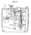
- Fig. 5 is a plan view of a sliding mechanism of the paper feed tray positioned just before the loading position within the copying machine main unit and a side fence
- Fig. 6 is a plan view of the configuration of the paper size detecting device together with the side fence and an end fence
- Fig. 3 is a perspective view of a paper feed tray and a detecting sensor
- Fig. 4 is a plan view of the paper feed tray positioned at a loading position within the copying machine main unit and the detecting sensor
- Fig. 5 is a plan view of a sliding mechanism of the paper feed tray positioned just before the loading position within the copying machine main unit and a side fence
- Fig. 6 is a plan view of the configuration of the paper size detecting device together with the side fence and an end fence
- FIG. 7 is an explanatory diagram of a relationship between corrugated portions formed at distal ends of first and second levers of the paper size detecting device and the detecting sensor
- Fig. 8 depicts a position of the second lever when the end fence is placed at a position corresponding to the minimum paper size
- Fig. 9 is a side view of only the side fence
- Fig. 10 is a side view of only the end fence and the first and the second levers.
- the paper feed tray 23 has a box-like tray main unit 23a with an opened top, and a pair of side fences 54a and 54b and an end fence 52 are slidably provided on the tray main unit 23a.
- a direction orthogonal to a conveying direction of a paper 53 is restricted by the pair of slidable side fences 54a and 54b, and the conveying direction of the paper 53 is restricted by the slidable end fence 52.
- the side fences 54a and 54b are coupled with racks 7 and 8 disposed on a back face side of a bottom of the tray main unit 23a.
- the racks 7 and 8 are coupled via a pinion gear 9, and the pair of side fences 54a and 54b are slid in directions in which they approximate to and separate from each other by the same distance by a rack and pinion mechanism.
- the end fence 52 is slid while being guided by an elongated hole 52a provided on the bottom of the tray main unit 23a.
- a bottom plate 5 that pushes up a leading edge side of stacked paper 53 in a paper feeding direction is provided at a portion of the bottom of the tray main unit 23a.
- a direction indicated by arrow 6 shown in Fig. 5 corresponds to a setting direction of the paper feed tray 23.
- An end fence interlocking shaft 3 is provided on a lower portion of the end fence 52 to extend downwardly, and the end fence interlocking shaft 3 is suspended downwardly via the elongated hole 52a.
- a side fence interlocking shaft 4 is provided downwardly on a lower portion of the side fence 54a of the side fences 54a and 54b that is positioned on a depth side to the setting direction (direction of arrow 6). The side fence interlocking shaft 4 is suspended downwardly via an elongated hole 54c.
- First and second levers 1 and 2 that are rotatably attached to a common supporting shaft 41 in an overlapping manner are provided on a lower portion of the bottom of the tray main unit 23a.
- the first lever 1 has a fan shape, and is formed with a guide elongated hole 1a in which the side fence interlocking shaft 4 is inserted with a clearance so as to be interlockingly rotated with sliding motion of the side fence 54a.
- the second lever 2 has an almost ginkgo leaf shape, and is formed with a guide elongated hole 2a in which the end fence interlocking shaft 3 is inserted with a clearance so as to be interlockingly rotated with sliding motion of the end fence 52.
- the first and the second levers 1 and 2 have arc-shaped side edges set at the same distance from the center line of the supporting shaft 41.
- a first corrugated portion 1b is formed on the arc-shaped side edge of the first lever 1, while a second corrugated portion 2b is formed on the arc-shaped side edge of the second lever 2.
- the first and the second levers 1 and 2 are provided such that the corrugated portions 1b and 2b are positioned within an outer diametrical size of the tray main unit 23a at a leading end of the setting direction of the tray main unit 23a.
- first and the second levers 1 and 2 are disposed in an overlapping manner, the first corrugated portion 1b of the first lever 1 and the second corrugated portion 2b of the second lever 2 are positioned in an overlapping manner, so that a plurality of composite corrugated portions can be formed by overlapping the first and the second corrugated portions 1b and 2b with each other with different angles.
- the detecting sensor 51 attached to a side plate 55 of the copying machine main unit 10 is provided with five push switches 51A, 51B, 51C, 51D, and 51E.
- the composite corrugated portion constituted of the corrugated portions 1b and 2b of the first and the second levers 1 and 2 are brought in pressure contact with the detecting sensor 51, so that arbitrary ones of the push switches 51A, 51B, 51C, 51D, and 51E corresponding to projections of the composite corrugated portion are pushed to output ON signals, as shown in Fig. 7 .
- the composite corrugated portion changes according to movements of the side fences 54a and 54b, and the end fence 52.
- the first and second levers 1 and 2 are pivoted in an overlapping manner, and a combination of the respective corrugated portions 1b and 2b of the first and the second levers 1 and 2 forms a pattern for pressing the push switches of the detecting sensor 51.
- Fig. 11 is a table showing paper sizes (Y corresponding to a lateral size and T corresponding to a longitudinal size) for respective destinations and ON/OFF states of the push switches of the detecting sensor 51 that are turned ON/OFF according to pattern combinations of the first and the second corrugated portions 1b and 2b at that time.
- "A" to "E” in the table shown in Fig. 11 denote the push switches 51A to 51E of the detecting sensor 51, and "0" denotes OFF (switch is not pressed: pattern corresponds to a recess), while “1” denotes ON (switch is pressed: pattern corresponds to a projection).
- a positional deviation may occur due to low attaching accuracy of parts required when the detecting sensor 51 is attached to the side plate 55 or when the side plate 55 is attached to the copying machine main unit 10 so that a paper size cannot be detected accurately.
- a first read rate (FRR) separation paper feeding device that separates sheets of paper in each paper feeding tray 23 from each other to convey them one by one, such as the one shown in Fig. 13 , has the following problems.
- a paper feeding device that nips paper between a feed roller and a separating member brought in pressure contact with the feed roller to convey the paper separately, as shown in Fig. 13 , paper is picked up from a paper stack (not shown) by a pickup roller 63 to be guided to a feed roller 61.
- the feed roller 61 rotated in a paper feeding direction shown with arrow 68 separates sheets of paper one by one from the paper stack in association with a reverse roller 62 that is applied with a predetermined torque in a direction reverse to the paper feeding direction by a torque limiter 70 to convey the sheets of paper one by one.
- a magnitude of the torque transmitted to the reverse roller 62 is limited by the torque limiter 70.
- the torque transmitted by the drive gear 62B is applied to the reverse roller 62 via the idle gear 62A provided on a shaft of the reverse roller 62 so as to mesh with the drive gear 62B and the reverse roller 62 brought in pressure contact with the feed roller 61 with a force of a resilient member (a spring 64 in this case) is driven by a gear tooth face pressure between the drive gear 62B and the idle gear 62A indicated by arrow 67 and an initial pressurizing force so that sheets of paper are separated and conveyed one by one.
- a resilient member a spring 64 in this case
- the feed roller 61 is stopped before the first paper passes through the nip. If the feed roller 61 is stopped at an exact correct point, a time in which the feed roller 61 is driven is long, therefore, occurrence of slippage can be suppressed to the minimum. Accordingly, when a paper size is known accurately, paper can be conveyed highly accurately.
- Fig. 1 is a plan view of the paper size detecting device corresponding to the invention, with the paper feed tray 23 drawn out.
- Fig. 2 is a plan view of the paper size detecting device, with the paper feed tray 23 set.
- the detecting sensor 51 is fixedly supported on a bracket 57.
- Guide pins 58 are provided so as to correspond to both ends of the opening 23c in a longitudinal direction thereof substantially in a standing manner, and the bracket 57 is attached to the guide pins 58 to be slidable in a direction of arrow "a" such that the detecting sensor 51 faces the opening 23c.
- Pressurizing members 59 such as coil springs are respectively attached to both ends of the bracket 57 to bias the bracket 57 in a direction separating from the side wall 23b of the paper feed tray 23.
- the bracket 57 is positioned by stoppers 58a provided at distal ends of the guide pins 58.
- One end of a detecting sensor pressing member 60 such as a coil spring is fixed to the side plate 55 of the copying machine main unit 10, and the other end thereof presses the bracket 57 when the paper feed tray 23 is set.
- the detecting sensor 51 is electrically connected to the copying machine main unit 10 via a connector such as a drawer connector (not shown).
- the bracket 57 is first pushed toward the side wall 23b of the paper feed tray 23 by the detecting sensor pressing member 60 to abut on the side wall 23b at a point "b", so that the detecting sensor 51 is positioned.
- the detecting sensor pressing member 60 can be formed of a resilient body such as a leaf spring and it is constituted so as to accommodate a positional relationship between the side plate 55 of the copying machine main unit 10 and the paper feed tray 23. With this configuration, distances to distal ends of the first and the second levers 1 and 2 can be set accurately. Accurate positioning with respect to lateral deviation shown in Fig. 12 is possible by the guide pins 58.
- the detecting sensor 51 is interlockingly separated from the first and the second levers 1 and 2 with the drawing-out operation, contact between the first and the second levers 1 and 2 and the detecting sensor 51 can be reliably prevented even at a time of setting sheets of paper.
- the paper size detector that detects a size of the paper set is provided integrally with the paper feed tray, the paper size can be detected with a higher accuracy.
Landscapes
- Engineering & Computer Science (AREA)
- Mechanical Engineering (AREA)
- Physics & Mathematics (AREA)
- General Physics & Mathematics (AREA)
- Sheets, Magazines, And Separation Thereof (AREA)
Claims (5)
- Papierzuführungsfach (23) für einen Apparat (10), das Folgendes umfasst:eine Fachhaupteinheit (23a), konfiguriert, um einen Stapel von Aufzeichnungsmedien (53) unterzubringen;eine erste Ausrichtungseinheit (54a, 54b), die in einer ersten Richtung gleitbar ist, und die konfiguriert ist, um eine Ausrichtung des Stapels der Aufzeichnungsmedien in der Fachhaupteinheit (23a) in der ersten Richtung auszuführen;eine zweite Ausrichtungseinheit (52), die in einer zweiten Richtung gleitbar ist, die senkrecht zu der ersten Richtung ist, und die konfiguriert ist, um eine Ausrichtung des Stapels von Aufzeichnungsmedien in der Fachhaupteinheit (23a) in der zweiten Richtung auszuführen;ein erstes bewegliches Glied (1), das einen ersten gewellten Abschnitt (1b) umfasst, und konfiguriert ist, um sich auf der Hauptfacheinheit (23a) entsprechend einer Gleitbewegung der ersten Ausrichtungseinheit (54a, 54b) zu drehen;ein zweites bewegliches Glied (2), das einen zweiten gewellten Abschnitt (2b) umfasst, und konfiguriert ist, um sich auf der Hauptfacheinheit (23a) entsprechend einer Gleitbewegung der zweiten Ausrichtungseinheit (52) zu drehen; wobei das erste bewegliche Glied (1) und das zweite bewegliche Glied (2) auf eine überlappende Art und Weise angeordnet sind, und wobei der erste gewellte Abschnitt (1b) des ersten beweglichen Glieds (1) und der zweite gewellte Abschnitt (2b) des zweiten beweglichen Glieds (2) auf eine überlapende Art und Weise angeordnet sind, sodass ein zusammengesetzter gewellter Abschnitt durch den ersten gewellten Abschnitt (1b) und den zweiten gewellten Abschnitt (2b) ausgebildet wird;eine Detektionseinheit (51), die integral mit der Fachhaupteinheit (23a) bereitgestellt wird und eine Vielzahl von Tastenschaltern (51A-51E) aufweist; und ein Unterstützungsglied (57), das die Detektionseinheit (51) in einer Richtung (a) elastisch (59) unterstützt, in welcher sich die Detektionseinehit (51) von einer Seitenwand (23b) der Fachhaupteinheit (23a) trennt, wobeiwenn das Papierzuführungsfach (23) in den Apparat geladen wird, die Detektionseinheit (51) zusammen mit dem Unterstützungsglied (57) in Richtung auf den zusammengesetzten gewellten Abschnitt bewegt wird, sodass die Vielzahl von Tastenschaltern (51A-51E) selektiv durch den zusammengesetzten gewellten Abschnitt gedrückt werden kann.
- Papierzuführungsfach nach Anspruch 1, wobei das erste bewegliche Glied (1) und das zweite bewegliche Glied (2) jeweils aus plattenähnlichen Gliedern besteht und auf einer unteren Hinterfläche der Hauptfacheinheit (23a) parallel zu einer Oberfläche (5) der Fachhaupteinheit (23a) angeordnet sind, auf welcher der Stapel der Aufzeichnungsmedien platziert ist.
- Papierzuführungsfach nach irgendeinem der Ansprüche 1 bis 2, wobei das erste bewegliche Glied (1) und das zweite bewegliche Glied (2) konzentrisch angebracht sind (41).
- Papierzuführungseinheit, der Folgendes umfasst:ein Papierzuführungsfach nach irgendeinem der Ansprüche 1 bis 3; undeine Zuführungseinheit, konfiguriert, um ein Aufzeichnungsmedium aus der Fachhaupteinheit (23a) aufzunehmen und das Aufzeichnungsmedium einer anderen Vorrichtung zuzuführen.
- Bilderzeugungsapparat (10), der Folgendes umfasst:ein Papierzuführungsfach nach irgendeinem der Ansprüche 1 bis 3;eine Bilderzeugungseinheit (100); konfiguriert, um ein Bild auf einem Aufzeichnungsmedium basierend auf eingegebenen Bilddaten auszubilden; undeine Zuführungseinheit, um wenigstens ein Aufzeichnungsmedium aus der Fachhaupteinheit (23a) aufzunehmen und das Aufzeichnungsmedium einer Bilderzeugungseinheit (100) zuzuführen.
Applications Claiming Priority (1)
| Application Number | Priority Date | Filing Date | Title |
|---|---|---|---|
| JP2004307052A JP4414860B2 (ja) | 2004-10-21 | 2004-10-21 | 給紙トレイ、給紙装置および画像形成装置 |
Publications (2)
| Publication Number | Publication Date |
|---|---|
| EP1650144A1 EP1650144A1 (de) | 2006-04-26 |
| EP1650144B1 true EP1650144B1 (de) | 2008-11-05 |
Family
ID=35520617
Family Applications (1)
| Application Number | Title | Priority Date | Filing Date |
|---|---|---|---|
| EP05017666A Expired - Lifetime EP1650144B1 (de) | 2004-10-21 | 2005-08-12 | Kassette mit Papiertransport, Papierzuführvorrichtung und Bilderzeugungsvorrichtung |
Country Status (5)
| Country | Link |
|---|---|
| US (1) | US7516955B2 (de) |
| EP (1) | EP1650144B1 (de) |
| JP (1) | JP4414860B2 (de) |
| CN (1) | CN100379659C (de) |
| DE (1) | DE602005010808D1 (de) |
Families Citing this family (20)
| Publication number | Priority date | Publication date | Assignee | Title |
|---|---|---|---|---|
| CN101190758B (zh) * | 2006-12-01 | 2010-12-29 | 虹光精密工业(苏州)有限公司 | 可侦测纸张尺寸的进纸装置 |
| US8052141B2 (en) | 2007-05-31 | 2011-11-08 | Ricoh Company, Limited | Recording-medium storage device and image forming apparatus |
| JP5055619B2 (ja) * | 2007-08-20 | 2012-10-24 | 株式会社リコー | シートサイズ検知装置・画像形成装置・シートサイズ検知方法 |
| US7731183B2 (en) * | 2007-09-10 | 2010-06-08 | Kabushiki Kaisha Toshiba | Paper feeding apparatus with paper size detectors |
| JP5200667B2 (ja) * | 2007-11-13 | 2013-06-05 | 株式会社リコー | 透過光量測定装置、媒体識別装置、媒体搬送装置及び画像形成装置 |
| US7984901B2 (en) * | 2008-08-19 | 2011-07-26 | Kabushiki Kaisha Toshiba | Paper feeding cassette |
| US7694960B2 (en) * | 2008-08-26 | 2010-04-13 | Hewlett-Packard Development Company, L.P. | Media size sensing system and method |
| JP5335457B2 (ja) * | 2009-01-29 | 2013-11-06 | キヤノン株式会社 | シート給送装置及び画像形成装置 |
| JP5317868B2 (ja) * | 2009-07-10 | 2013-10-16 | キヤノン株式会社 | 画像形成装置 |
| KR20110081703A (ko) * | 2010-01-08 | 2011-07-14 | 삼성전자주식회사 | 용지적재대, 용지급지장치와 이를 가지는 화상형성장치 및 그 제어방법 |
| JP5380477B2 (ja) * | 2010-11-11 | 2014-01-08 | 京セラドキュメントソリューションズ株式会社 | 用紙サイズ検知機構及びそれを備えた画像形成装置 |
| JP5477355B2 (ja) * | 2011-10-03 | 2014-04-23 | コニカミノルタ株式会社 | 給紙装置 |
| JP6064838B2 (ja) | 2013-08-23 | 2017-01-25 | ブラザー工業株式会社 | 画像形成装置 |
| JP6272035B2 (ja) * | 2014-01-09 | 2018-01-31 | キヤノン株式会社 | シート給送装置及び画像形成装置 |
| US10065824B2 (en) | 2015-12-16 | 2018-09-04 | Ricoh Company, Ltd. | Stacking apparatus |
| US9580259B1 (en) * | 2016-04-22 | 2017-02-28 | Lexmark International, Inc. | Removable media tray having a rack and pinion media length sensing mechanism operable by a rear restraint |
| US10988330B2 (en) * | 2016-09-08 | 2021-04-27 | Hewlett-Packard Development Company, L.P. | Media size detector |
| KR102253138B1 (ko) | 2016-09-09 | 2021-05-14 | 주식회사 엘지화학 | 글리세린 탈수 반응용 촉매, 이의 제조 방법 및 상기 촉매를 이용한 아크롤레인의 제조 방법 |
| JP7176317B2 (ja) * | 2018-09-18 | 2022-11-22 | 富士フイルムビジネスイノベーション株式会社 | 記録材収容装置および画像形成装置 |
| JP7125890B2 (ja) * | 2018-10-26 | 2022-08-25 | 富士通コンポーネント株式会社 | プリンタ装置 |
Citations (1)
| Publication number | Priority date | Publication date | Assignee | Title |
|---|---|---|---|---|
| US6254085B1 (en) * | 1998-10-21 | 2001-07-03 | Samsung Electronics Co., Ltd. | Paper feeding apparatus for printing device |
Family Cites Families (24)
| Publication number | Priority date | Publication date | Assignee | Title |
|---|---|---|---|---|
| JP4065101B2 (ja) | 1999-10-25 | 2008-03-19 | 株式会社リコー | 両面画像記録方法及び装置 |
| JPS59227630A (ja) * | 1983-06-08 | 1984-12-20 | Fuji Xerox Co Ltd | 積層枚葉紙位置決め装置 |
| JPH01214530A (ja) * | 1988-02-20 | 1989-08-28 | Canon Inc | 画像形成装置 |
| US5172903A (en) * | 1990-09-28 | 1992-12-22 | Konica Corporation | Paper feed cassette |
| JP2887009B2 (ja) * | 1991-06-03 | 1999-04-26 | キヤノン株式会社 | シート載置装置 |
| US5327206A (en) * | 1991-07-17 | 1994-07-05 | Minolta Camera Kabushiki Kaisha | Image forming apparatus including a sheet refeeding unit |
| KR0140628B1 (ko) * | 1994-06-24 | 1998-07-15 | 김광호 | 급지카세트 |
| JP3081117B2 (ja) * | 1994-10-20 | 2000-08-28 | 株式会社沖データ | 用紙カセット装置 |
| US5737682A (en) | 1995-10-03 | 1998-04-07 | Ricoh Company, Ltd. | Duplex sheet feeding device for an image forming apparatus |
| JP3669604B2 (ja) * | 1996-04-17 | 2005-07-13 | 東北リコー株式会社 | 孔版印刷装置 |
| KR100208397B1 (ko) * | 1997-02-13 | 1999-07-15 | 윤종용 | 팩시밀리의 원고크기 감지장치 |
| KR19990078056A (ko) | 1998-03-23 | 1999-10-25 | 이토가 미찌야 | 용지위치조절기구를갖는용지안내장치및그장치를이용하는화상형성장치 |
| JP2000118729A (ja) | 1998-10-19 | 2000-04-25 | Minolta Co Ltd | ユニバーサル給紙トレイの用紙サイズ検出方法と装置 |
| JP4121209B2 (ja) * | 1999-02-26 | 2008-07-23 | 東北リコー株式会社 | 画像形成装置における給紙装置 |
| FR2799141B1 (fr) * | 1999-10-01 | 2002-01-25 | Neopost Ind | Dispositif de taquage pour alimenteur de documents |
| GB9925552D0 (en) * | 1999-10-29 | 1999-12-29 | Ncr Int Inc | Self-service terminal |
| JP4077163B2 (ja) | 2000-03-22 | 2008-04-16 | 株式会社リコー | シート部材搬送装置及び画像形成装置 |
| JP3829053B2 (ja) | 2000-10-11 | 2006-10-04 | 株式会社リコー | 用紙サイズ検出装置及びこれを備えた画像形成装置 |
| KR100388995B1 (ko) * | 2000-12-29 | 2003-06-25 | 삼성전자주식회사 | 화상형성기의 용지 사이즈 인식장치 |
| JP3926639B2 (ja) | 2001-03-06 | 2007-06-06 | 株式会社リコー | 用紙の反転方法及び用紙反転装置並びに画像形成装置 |
| US6711377B2 (en) | 2001-04-20 | 2004-03-23 | Ricoh Company, Ltd. | Double-sided image forming device having a turnable guide guiding a rear end of a large-size sheet |
| US6688592B1 (en) * | 2002-07-30 | 2004-02-10 | Hewlett-Packard Development Company, L.P. | Paper tray for a printing mechanism |
| JP4294572B2 (ja) * | 2004-03-05 | 2009-07-15 | 株式会社リコー | 給紙カセット、記録媒体サイズ検知装置及び画像形成装置 |
| KR100565088B1 (ko) * | 2004-10-21 | 2006-03-30 | 삼성전자주식회사 | 급지 카세트 및 이를 구비한 화상형성장치 |
-
2004
- 2004-10-21 JP JP2004307052A patent/JP4414860B2/ja not_active Expired - Fee Related
-
2005
- 2005-08-12 DE DE602005010808T patent/DE602005010808D1/de not_active Expired - Lifetime
- 2005-08-12 EP EP05017666A patent/EP1650144B1/de not_active Expired - Lifetime
- 2005-08-15 US US11/203,344 patent/US7516955B2/en not_active Expired - Fee Related
- 2005-10-19 CN CNB2005101141120A patent/CN100379659C/zh not_active Expired - Fee Related
Patent Citations (1)
| Publication number | Priority date | Publication date | Assignee | Title |
|---|---|---|---|---|
| US6254085B1 (en) * | 1998-10-21 | 2001-07-03 | Samsung Electronics Co., Ltd. | Paper feeding apparatus for printing device |
Also Published As
| Publication number | Publication date |
|---|---|
| JP2006117377A (ja) | 2006-05-11 |
| DE602005010808D1 (de) | 2008-12-18 |
| EP1650144A1 (de) | 2006-04-26 |
| CN1765715A (zh) | 2006-05-03 |
| CN100379659C (zh) | 2008-04-09 |
| US7516955B2 (en) | 2009-04-14 |
| US20060087073A1 (en) | 2006-04-27 |
| JP4414860B2 (ja) | 2010-02-10 |
Similar Documents
| Publication | Publication Date | Title |
|---|---|---|
| US7516955B2 (en) | Paper feed tray, paper feeding apparatus, and image forming apparatus including paper aligning units | |
| US6928259B2 (en) | Finishing apparatus | |
| EP1571107B1 (de) | Kassette für Papiertransport, Detektor zum Abtasten der Grösse eines Aufzeichnungsmediums und Bilderzeugungsvorrichtung | |
| US8328186B2 (en) | Paper sheet processing apparatus, and paper sheet processing method | |
| US8632068B2 (en) | Image forming apparatus with sheet push member pushing in horizontal direction | |
| US7441769B2 (en) | Paper feed tray, paper feeding apparatus, and image forming apparatus using movable members to move aligning units and lock in place | |
| US7997574B2 (en) | Image forming apparatus and control method thereof | |
| EP0367200A2 (de) | Bogenzuführvorrichtung | |
| JPH0558465A (ja) | 記録紙サイズ識別構造 | |
| US7087007B2 (en) | Sheet post-processing device and image forming apparatus | |
| JP4324562B2 (ja) | シートサイズ検知装置及び画像形成装置 | |
| JPH10329956A (ja) | 給送カセットおよび画像形成装置 | |
| JP7484462B2 (ja) | シート後処理装置及び画像形成システム | |
| CN108861692B (zh) | 片材供给设备和成像设备 | |
| JP3877510B2 (ja) | 画像形成装置の用紙排出装置 | |
| US11279573B2 (en) | Sheet holder, sheet feeding device incorporating the sheet holder, and image forming apparatus incorporating the sheet holder | |
| US7556252B2 (en) | Sheet post-processing apparatus | |
| JP2002284425A (ja) | シート処理装置及びこれを備える画像形成装置 | |
| JP7537122B2 (ja) | シート排出装置およびそれを備えた原稿搬送装置並びに画像形成装置 | |
| JPS62191334A (ja) | 自動両面コピ−装置 | |
| JP2001179653A (ja) | ステープル装置 | |
| JP3480809B2 (ja) | 画像形成装置の搬送装置 | |
| JP3902858B2 (ja) | シートカセット及び画像形成装置 | |
| JP3384107B2 (ja) | シート処理装置 | |
| JP3761989B2 (ja) | シート積載装置及び画像形成装置 |
Legal Events
| Date | Code | Title | Description |
|---|---|---|---|
| PUAI | Public reference made under article 153(3) epc to a published international application that has entered the european phase |
Free format text: ORIGINAL CODE: 0009012 |
|
| 17P | Request for examination filed |
Effective date: 20060301 |
|
| AK | Designated contracting states |
Kind code of ref document: A1 Designated state(s): AT BE BG CH CY CZ DE DK EE ES FI FR GB GR HU IE IS IT LI LT LU LV MC NL PL PT RO SE SI SK TR |
|
| AX | Request for extension of the european patent |
Extension state: AL BA HR MK YU |
|
| AKX | Designation fees paid |
Designated state(s): DE FR GB |
|
| GRAP | Despatch of communication of intention to grant a patent |
Free format text: ORIGINAL CODE: EPIDOSNIGR1 |
|
| GRAS | Grant fee paid |
Free format text: ORIGINAL CODE: EPIDOSNIGR3 |
|
| GRAA | (expected) grant |
Free format text: ORIGINAL CODE: 0009210 |
|
| AK | Designated contracting states |
Kind code of ref document: B1 Designated state(s): DE FR GB |
|
| REG | Reference to a national code |
Ref country code: GB Ref legal event code: FG4D |
|
| REF | Corresponds to: |
Ref document number: 602005010808 Country of ref document: DE Date of ref document: 20081218 Kind code of ref document: P |
|
| PLBE | No opposition filed within time limit |
Free format text: ORIGINAL CODE: 0009261 |
|
| STAA | Information on the status of an ep patent application or granted ep patent |
Free format text: STATUS: NO OPPOSITION FILED WITHIN TIME LIMIT |
|
| 26N | No opposition filed |
Effective date: 20090806 |
|
| REG | Reference to a national code |
Ref country code: FR Ref legal event code: PLFP Year of fee payment: 12 |
|
| PGFP | Annual fee paid to national office [announced via postgrant information from national office to epo] |
Ref country code: GB Payment date: 20160819 Year of fee payment: 12 Ref country code: DE Payment date: 20160822 Year of fee payment: 12 |
|
| PGFP | Annual fee paid to national office [announced via postgrant information from national office to epo] |
Ref country code: FR Payment date: 20160822 Year of fee payment: 12 |
|
| REG | Reference to a national code |
Ref country code: DE Ref legal event code: R119 Ref document number: 602005010808 Country of ref document: DE |
|
| GBPC | Gb: european patent ceased through non-payment of renewal fee |
Effective date: 20170812 |
|
| REG | Reference to a national code |
Ref country code: FR Ref legal event code: ST Effective date: 20180430 |
|
| PG25 | Lapsed in a contracting state [announced via postgrant information from national office to epo] |
Ref country code: GB Free format text: LAPSE BECAUSE OF NON-PAYMENT OF DUE FEES Effective date: 20170812 Ref country code: DE Free format text: LAPSE BECAUSE OF NON-PAYMENT OF DUE FEES Effective date: 20180301 |
|
| PG25 | Lapsed in a contracting state [announced via postgrant information from national office to epo] |
Ref country code: FR Free format text: LAPSE BECAUSE OF NON-PAYMENT OF DUE FEES Effective date: 20170831 |