EP1650072A2 - Antriebskraftverteilungs- Steuerungsgerät für Fahrzeuge - Google Patents
Antriebskraftverteilungs- Steuerungsgerät für Fahrzeuge Download PDFInfo
- Publication number
- EP1650072A2 EP1650072A2 EP05023067A EP05023067A EP1650072A2 EP 1650072 A2 EP1650072 A2 EP 1650072A2 EP 05023067 A EP05023067 A EP 05023067A EP 05023067 A EP05023067 A EP 05023067A EP 1650072 A2 EP1650072 A2 EP 1650072A2
- Authority
- EP
- European Patent Office
- Prior art keywords
- driving force
- force distribution
- yaw moment
- control
- lateral acceleration
- Prior art date
- Legal status (The legal status is an assumption and is not a legal conclusion. Google has not performed a legal analysis and makes no representation as to the accuracy of the status listed.)
- Granted
Links
- 238000009826 distribution Methods 0.000 title claims abstract description 228
- 230000001133 acceleration Effects 0.000 claims abstract description 138
- 230000003247 decreasing effect Effects 0.000 claims description 11
- 230000004044 response Effects 0.000 claims description 11
- 238000010586 diagram Methods 0.000 description 19
- 230000007246 mechanism Effects 0.000 description 17
- 230000009467 reduction Effects 0.000 description 13
- 230000000694 effects Effects 0.000 description 5
- 229920006395 saturated elastomer Polymers 0.000 description 3
- 230000005540 biological transmission Effects 0.000 description 2
- 230000004048 modification Effects 0.000 description 2
- 238000012986 modification Methods 0.000 description 2
- 238000011084 recovery Methods 0.000 description 2
- NAWXUBYGYWOOIX-SFHVURJKSA-N (2s)-2-[[4-[2-(2,4-diaminoquinazolin-6-yl)ethyl]benzoyl]amino]-4-methylidenepentanedioic acid Chemical compound C1=CC2=NC(N)=NC(N)=C2C=C1CCC1=CC=C(C(=O)N[C@@H](CC(=C)C(O)=O)C(O)=O)C=C1 NAWXUBYGYWOOIX-SFHVURJKSA-N 0.000 description 1
- 238000012935 Averaging Methods 0.000 description 1
- 238000006243 chemical reaction Methods 0.000 description 1
- 230000007704 transition Effects 0.000 description 1
Images


Classifications
-
- B—PERFORMING OPERATIONS; TRANSPORTING
- B60—VEHICLES IN GENERAL
- B60K—ARRANGEMENT OR MOUNTING OF PROPULSION UNITS OR OF TRANSMISSIONS IN VEHICLES; ARRANGEMENT OR MOUNTING OF PLURAL DIVERSE PRIME-MOVERS IN VEHICLES; AUXILIARY DRIVES FOR VEHICLES; INSTRUMENTATION OR DASHBOARDS FOR VEHICLES; ARRANGEMENTS IN CONNECTION WITH COOLING, AIR INTAKE, GAS EXHAUST OR FUEL SUPPLY OF PROPULSION UNITS IN VEHICLES
- B60K23/00—Arrangement or mounting of control devices for vehicle transmissions, or parts thereof, not otherwise provided for
- B60K23/08—Arrangement or mounting of control devices for vehicle transmissions, or parts thereof, not otherwise provided for for changing number of driven wheels, for switching from driving one axle to driving two or more axles
- B60K23/0808—Arrangement or mounting of control devices for vehicle transmissions, or parts thereof, not otherwise provided for for changing number of driven wheels, for switching from driving one axle to driving two or more axles for varying torque distribution between driven axles, e.g. by transfer clutch
Definitions
- the present invention is related to a driving force distribution control apparatus for performing both a driving force distribution between a front wheel and a rear wheel and a driving force distribution between a left wheel and a right wheel.
- JP-A-07-108840 is a technical idea capable of controlling a torque distribution between a front wheel and a rear wheel by a differential limiting clutch provided on a center differential, and also capable of controlling a torque distribution between a left wheel and a right wheel by a torque transfer mechanism.
- the torque transfer mechanism is constituted by a gear shifter mechanism and a transfer capacity variable control type torque transfer mechanism, which are provided on a rear differential.
- JP-A-07-108840 owns the following problem. That is, since the driving force distribution control for the front and rear wheels and the driving force distribution control for the right and left wheels are independently carried out in response to the driving conditions of the vehicle, in such a case that both the control operation by which the driving force of the front and rear wheels is distributed so as to apply yaw moment to the vehicle, and the control operation by which the driving force of the right and left wheels is distributed so as to apply yaw moment to the vehicle are actuated, these control operations may be overlapped with each other, or may interfere with each, depending upon the operation timing thereof. Then, the vehicle is brought into unstable driving condition, or the target effect may not be achieved in accordance with values of yaw moment which are applied to the vehicle.
- One or more embodiments of the present invention provides a driving force distribution control apparatus capable of properly actuating both a driving force distribution control operation of front and rear wheels and a driving force distribution control operation of right and left wheels, while these distribution control operations own the maximum effects in various vehicle driving scenes, and also, capable of maintaining both a stability and a turning round characteristic of the vehicle under optimum characteristics.
- a driving force distribution control apparatus is provided with a front/rear driving force distribution controller for controlling a driving force distribution between a front wheel side and a rear wheel side; and a right/left driving force distribution controller for controlling a driving force distribution between a left wheel and a right wheel of at least one of the front wheel side and the rear wheel side.
- a control amount by the front/rear driving force distribution controller is decreased in response to at least an accelerating condition
- a control amount set by the right/left driving force distribution controller is decreased in response to at least the accelerating condition.
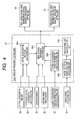
- reference numeral 1 indicates an engine which is arranged at a front portion of a vehicle.
- the driving force produced from this engine 1 is transferred from an automatic gear shifter apparatus 2 (which is illustrated, while torque converter and the like are also contained) arranged at a rear portion of the engine 1 via a transmission power shaft 2a to a transfer 3.
- an automatic gear shifter apparatus 2 which is illustrated, while torque converter and the like are also contained
- the driving force transferred to the transfer 3 is entered via a rear drive shaft 4, a propeller shaft 5, and a drive pinion shaft unit 6 to a rear wheel final reduction gear apparatus 7, and on the other hand, is entered via a reduction drive gear 8, a reduction driven gear 9, and a front drive shaft 10 which constitutes a drive pinion shaft unit, to a front wheel final reduction gear apparatus 11.
- the automatic gear shifter apparatus 2, the transfer 3, the front wheel final reduction gear apparatus 11, and the like have been provided in a case 12.
- the driving force entered to the rear wheel final reduction gear apparatus 7 is transferred via a left rear wheel drive shaft 13rl to a left rear wheel 14rl, and is transferred via a right rear wheel drive shaft 13rr to a right real wheel 14rr.
- the rear wheel final redaction gear apparatus 7 has been constituted by employing a right/left driving force distribution mechanism (will be explained later).
- the driving force entered to the front wheel final reduction gear apparatus 11 is transferred via a left front wheel drive shaft 13fl to a left rear wheel 14rl, and is transferred via a right front wheel drive shaft 13fr to a right front wheel 14fr.
- the transfer 3 has been constituted by employing a wet type multi-plate clutch (transfer clutch) 15, and a transfer piston 16.
- the wet type multi-plate clutch 15 functions as a torque transfer capacity variable type clutch, and is arranged by alternately overlapping a drive plate 15a provided on the side of the reduction drive gear 8 and a driven plate 15b provided on the side of the rear drive shaft 4.
- the transfer piston 16 applies transfer clutch torque of the transfer clutch 15 in a variable manner.
- this vehicle may constitute a front engine/front drive vehicle based (FF based) four-wheel drive vehicle which can very a torque distribution ratio with respect to the front wheel and the rear wheel, for example, between 100:0 and 50:50 by controlling depression force produced by the transfer piston 16, and by controlling the transfer clutch torque of the transfer clutch 15.
- FF based front engine/front drive vehicle based
- the depression force of the transfer piston 16 is applied by a transfer clutch driving unit 80 which is arranged by an oil pressure circuit containing a plurality of solenoid valves and the like.
- a control signal (namely, output signal produced in response to transfer clutch torque for solenoid valve) which drives this transfer clutch driving unit 80 is outputted from a driving force distribution control unit 60 (will be explained later).
- the rear wheel final reduction gear apparatus 7 has been arranged in such a manner that a distribution of driving force to the left rear wheel 14fl and the right rear wheel 14fr can be freely controlled in a variable manner in response to a driving force distribution ratio set by a driving force distribution control unit 60 (will be discussed later).
- this rear wheel final reduction gear apparatus 7 has been mainly arranged by employing a differential mechanism unit 30, a gear mechanism unit 31, and a clutch mechanism unit 32.
- the differential mechanism 30 has been arranged by, for instance, a bevel gear type differential mechanism unit (differential apparatus).
- a final gear 36 has been formed in a circumferential manner on a differential case 35 of this differential mechanism unit 30, while this final gear 36 is meshed with a drive pinion 6a provided at a rear end of the drive pinion shaft unit 6.
- One pair of differential pinions 37 have been pivotally supported within the differential case 35, and the left drive shaft 13rl and the right drive shaft 13rr have been coupled to a left side gear 381 and a right side gear 38r, which are meshed with these differential pinions 37.
- the gear mechanism unit 31 has been arranged by employing first and second gears 40 and 41 which are fixedly provided on the left rear wheel drive shaft 13rl; third and fourth gears 42 and 43 which are fixedly provided on the right rear wheel drive shaft 13rr; and also, fifth to eighth gears 44 to 47 which are meshed with these first to fourth gears 40 to 43, respectively.
- the second gear 41 has been constituted by such a gear having a larger diameter than that of the first gear 40, and a total gear tooth number Z2 has been set to be larger than a gear tooth number Z1 of the first gear 40.
- the fifth gear 44 to the eighth gear 47 have been arranged on an axial center of the same rotation shaft which is located parallel to the left drive shaft 13rl and the right drive shaft 13rr.
- the fifth gear 44 constructs a first gear train by being meshed with the first gear 40, and a total gear tooth number Z5 thereof has been set in such a manner that a gear ratio (Z5/Z1) of the first gear train is selected to be, for example, "1.0".
- the sixth gear 45 constructs a second gear train by being meshed with the second gear 41, and a total gear tooth number Z6 thereof has been set in such a manner that a gear ratio (Z6/Z2) of the second gear train is selected to be, for example, "0.9".
- the seventh gear 46 constructs a third gear train by being meshed with the third gear 42, and a total gear tooth number Z7 thereof has been set in such a manner that a gear ratio (Z7/Z3) of the third gear train is selected to be, for example, "1.0".
- the eighth gear 47 constructs a fourth gear train by being meshed with the fourth gear 43, and a total gear tooth number Z8 thereof has been set in such a manner that a gear ratio (Z8/Z4) of the fourth gear train is selected to be, for example, "0.9".
- the clutch mechanism unit 32 has been arranged by employing a first oil pressure multi-plate clutch 48 for engaging between the fifth gear 44 and the eighth gear 47 in a freely connecting/disconnecting manner, and a second oil pressure multi-plate clutch 49 for engaging between the sixth gear 45 and the seventh gear 46 in a freely connecting/disconnecting manner.
- an oil pressure value used to engage each of the oil pressure multi-plate clutches 48 and 49 corresponds to a value for actuating the rear clutch driving unit 90 in response to a control amount set by the driving force distribution control unit 60.
- a torque distribution amount may be varied, depending upon a Targe oil pressure value, or a small oil pressure value. It should be noted that a detailed structure of this sort of final reduction gear apparatus has been described in, for example, JP-A-11-263140, and is not limited only to the structure explained in this embodiment mode.
- wheel speeds ⁇ fl, ⁇ fr, ⁇ rl, and ⁇ rr of the respective wheels 14fl, 14fr, 14rl, and 14rr are detected by wheel speed sensors 51fl, 51fr, 51rl, and 51rr.
- a steering wheel angle " ⁇ H” is sensed by a steering wheel angle sensor 52; lateral acceleration (will be abbreviated as “actual lateral acceleration “ hereinafter) (d 2 y/dt 2 ) which is actually produced on the vehicle is sensed by a lateral acceleration sensor 53; front/rear acceleration (will be abbreviated as “actual front/rear acceleration” hereinafter) (d 2 xe/dt 2 ) which is actually produced on the vehicle is sensed by a front/rear acceleration sensor 54; and a yaw rate (will be abbreviated as “actual yaw rate” hereinafter) ( ⁇ ) which is actually provided on the vehicle is sensed by a yaw rate sensor 55, and then, the output signals of these sensors are inputted to the driving force distribution control unit 60.
- the driving force distribution control unit 60 may have functions such as both a front/rear driving force distribution controller and a right/left driving force distribution controller.
- the driving force distribution control unit 60 calculates the front/rear driving force distribution by the transfer clutch 15 as transfer clutch torque TLSDV, and then, outputs the calculated transfer clutch torque TLSDV to the transfer clutch driving unit 80.
- the driving force distribution control unit 60 calculates the right/left driving force distribution by the clutch mechanism unit 32 of the rear wheel final reduction gear apparatus 7 as rear clutch torque TRY, and then, outputs the calculated rear clutch torque TRY to the rear clutch driving unit 90.
- the driving force distribution control unit 60 has been mainly arranged by a vehicle speed calculating unit 61, a lateral acceleration/steering wheel angle gain calculating unit 62, a reference lateral acceleration calculating unit 63, a basic addition yaw moment setting unit 64, a reference front/rear acceleration calculating unit 65, a front/rear driving force distribution control addition yaw moment setting unit 66, a front/rear driving force distribution cooperative control gain calculating unit 67, a front /rear driving force distribution cooperative control addition yaw moment calculating unit 68, a transfer clutch torque converting control unit 69, a right/left driving force distribution control addition yaw moment setting unit 70, a right/left driving force distribution cooperative control gain calculating unit 71, a right/left driving force distribution cooperative control addition yaw moment calculating unit 72, and a rear clutch torque converting control unit 73.
- sensor signals are entered from the vehicle speed sensors of the four wheels, namely, the wheel speeds ⁇ fl, ⁇ fr, ⁇ rl, and ⁇ rr of the respective vehicles 14fl, 14fr, 14rl, and 14rr are entered from the respective vehicle speed sensors 41fl, 51fr, 51rl, and 51rr.
- the vehicle speed "V" is entered from the vehicle speed calculating unit 61. Then, this lateral acceleration/steering wheel angle gain calculating unit 62 calculates a lateral acceleration/steering wheel angle gain "Gy" in accordance with the below-mentioned formula (1), and then, outputs the calculated lateral acceleration/steering wheel angle gain "Gy" to the the reference lateral acceleration calculating unit 63, the basic addition yaw moment setting unit 64, the front/rear driving force distribution cooperative control gain calculating unit 67, and the right/left driving force distribution cooperative control gain calculating unit 71.
- this reference lateral acceleration calculating unit 63 calculates reference lateral acceleration (d 2 yr/dt 2 ) from a drive condition of the vehicle, while this reference lateral acceleration indicates a relationship between lateral acceleration and actual lateral acceleration, which are predicted based upon a linear vehicle motion model.
- this reference lateral acceleration calculating unit 63 outputs the calculated reference lateral acceleration to the basic addition yaw moment setting unit 64, the front/rear driving force distribution cooperative control gain calculating unit 67, and the right/left driving force distribution cooperative control gain calculating unit 71.
- ( d 2 yr / dt 2 ) ( 1 / ( 1 + Ty ⁇ s ) ) ⁇ ( d 2 yss / dt 2 )
- symbol “s” shows a differential operator
- symbol “Ty” indicates a primary delay time constant of the lateral acceleration
- symbol "(d 2 yss/dt 2 )" represents symbol-added reference lateral acceleration without considering a delay.
- symbol (d 2 ysm/dt 2 ) indicates non-symbol reference lateral acceleration which is saturated by symbol (d 2 yx/dt 2 ) (will be explained later).
- symbol (d 2 yx/dt 2 ) shows quasi-lateral acceleration which saturates the reference lateral acceleration, and is calculated based upon either the below-mentioned formula (5) or formula (6):
- ( d 2 yx / dt 2 ) Gy ⁇ ⁇ HMax ⁇ ( ( 10 - ( d 2 y / dt 2 ) ) / 10 ) + ( d 2 y / dt 2 )
- symbol " ⁇ HMax" indicates a maximum steering wheel angle.
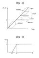
- the quasi-lateral acceleration (d 2 yx/dt 2 ) which saturates the reference lateral acceleration set in the above-explained formulae (5) and (6) is represented by a characteristic diagram; such a characteristic diagram shown in Fig. 11 is given.
- the reference lateral acceleration is saturated by 10 m/s 2 .
- a characteristic of the reference lateral acceleration (d 2 yr/dt 2 ) is represented in Fig. 12, while this reference lateral acceleration indicates a relationship between actual lateral acceleration and lateral acceleration which is predicted based upon the linear vehicle motion model from the set drive condition of the vehicle.
- the reference lateral acceleration (d 2 yr/dt 2 ) is set in such a manner that when a road surface " ⁇ " is high and the actual lateral acceleration (d 2 y/dt 2 ) is large, this reference lateral acceleration (d 2 yr/dt 2 ) is suppressed to be a small value, and conversely, when a road surface " ⁇ " is low and the actual lateral acceleration (d 2 y/dt 2 ) is small in the relationship with (Gy ⁇ H), this reference lateral acceleration (d 2 yr/dt 2 ) takes a large value.
- the steering wheel angle " ⁇ H” is inputted from the steering wheel angle sensor 52; (d 2 y/dt 2 ) is inputted from the lateral acceleration sensor 53; an actual yaw rate “ ⁇ ” is inputted from the yaw rate sensor 55; the vehicle speed “V” is inputted from the vehicle speed calculating unit 61; a lateral acceleration/steering wheel angle gain “Gy” is inputted from the lateral acceleration/steering wheel angle gain calculating unit 60; and also, the reference lateral acceleration (d 2 yr/dt 2 ) is inputted from the reference lateral acceleration calculating unit 63.
- the basic addition yaw moment setting unit 64 calculates the basic addition yaw moment "Mz ⁇ " based upon these input signals, and then, outputs this calculated basic addition yow moment "Mz ⁇ '' to the front/rear driving force distribution control addition yaw moment setting unit 66, and the right/left driving force distribution control addition yaw moment setting unit 70.
- This basic addition yaw moment setting 64 has been mainly arranged by a lateral acceleration deviation calculating unit 64a, a yaw rate/steering wheel angle gain calculating unit 64b, a yaw rate sensitive gain calculating unit 64c, a lateral acceleration deviation sensitive gain calculating unit 64d, and a basic addition yaw moment calculating unit 64e.
- the lateral acceleration deviation calculating unit 64a calculates a lateral acceleration deviation (d 2 ye/dt 2 ) based upon the below-mentioned formula (10), and outputs this calculated lateral acceleration deviation to the basic addition yaw moment calculating unit 64e.
- ( d 2 ye / dt 2 ) ( d 2 y / dt 2 ) - ( d 2 yr / dt 2 )
- the vehicle speed "V” from the vehicle speed calculating unit 61 is inputted to the yaw rate/steering wheel angle gain calculating unit 64b.
- the yaw rate/steering wheel angle gain calculating unit 64b calculates a yaw rate/steering wheel angle gain "GY” based upon the below-mentioned formula (11), and then, outputs the calculated yaw rate/steering wheel gain "Gy” to the yaw rate sensitive gain calculating unit 64c.
- G ⁇ ( 1 / ( 1 + A ⁇ V 2 ) ) ⁇ ( V / L ) ⁇ ( 1 / n )
- K ⁇ K ⁇ / G ⁇
- symbol “K ⁇ ” indicates a steering angle sensitive gain.
- symbol “Lf” indicates a front wheel-to-gravity center distance
- symbol “Kf” shows equivalent cornering power of the front wheel.
- yaw moment calculating unit 64e the steering wheel angle " ⁇ H" from the steering wheel angle sensor 52 is inputted; the actual yaw rate “ ⁇ ” from the yaw rate sensor 55 is inputted; the lateral acceleration deviation (d 2 ye/dt 2 ) from the lateral acceleration deviation calculating unit 64a is inputted; the yaw rate sensitive gain "K ⁇ " from the yaw rate sensitive gain calculating unit 64d is inputted; and also, the lateral acceleration deviation sensitive gain "Ky” from the lateral acceleration deviation sensitive gain calculating unit 64d is inputted.
- the basic addition yaw rate moment calculating unit 64e calculates basic addition yaw moment Mz ⁇ in accordance with the below-mentioned formula (15), and outputs this calculated basic addition yaw moment Mz ⁇ to both the front/rear driving force distribution control addition yaw moment setting unit 66 and the right/left driving force distribution control addition yaw moment setting unit 70.
- Mz ⁇ - K ⁇ ⁇ ⁇ + Ky ⁇ ( d 2 ye / dt 2 ) + K ⁇ ⁇ ⁇ H
- a term of "-K ⁇ ” constitutes yaw moment which is sensible to the yaw rate " ⁇ "
- a term of "K ⁇ . ⁇ H” constitutes yaw moment which is sensible to the steering wheel angle " ⁇ H”
- a term of "Ky ⁇ (d 2 ye/dt 2 )" constitutes a corrected value of the yaw moment.
- the actual lateral acceleration (d 2 y/dt 2 ) is inputted from the lateral acceleration sensor 53 to the reference front/rear acceleration calculating unit 65. Then, in order to calculate both a front/rear driving force distribution cooperative control gain "KcV”, and a right/left driving force distribution cooperative control gain "KcY", the reference front/rear acceleration calculating unit 65 sets reference front/rear acceleration (d 2 xc/dt 2 ) used in such a case that emphasizing/deemphasizing of acceleration operations with respect to the road plane " ⁇ " are considered in accordance with the below-mentioned formula (16), formula (17), or formula (18).
- the reference front/rear acceleration calculating unit 65 outputs the calculated reference front/rear acceleration to both the front/rear driving force distribution cooperative control gain calculatingunit 67 and the right/left driving force distribution cooperative control gain calculating unit 71:
- ⁇ 1 - - - ( d 2 xc / dt 2 ) 1
- ⁇ 3 - - - ( d 2 xc / dt 2 )
- > 3 - - - ( d 2 xc / dt 2 ) 3
- the actual lateral acceleration (d 2 y/dt 2 ) from the lateral acceleration sensor 53 is entered; the actual yaw rate " ⁇ " from the yaw rate sensor 55 is entered; the vehicle speed V from the vehicle speed calculating unit 61 is entered; and also the basic addition yaw-moment "Mz ⁇ " from the basic addition yaw moment setting unit 64 is inputted.
- the front/rear driving force distribution control addition yawmoment setting unit 66 calculates front/rear driving force distribution control addition yaw moment "MVz ⁇ " based upon these input signals, and thus, outputs this calculated front/rear driving force distribution control addition yow moment "MVz ⁇ " to the front/rear driving force distribution cooperative control addition yaw moment calculating unit 68.
- This front rear driving force distribution control addition yaw moment setting unit 66 has been mainly arranged by a low-speed-drive vehicle speed sensitive gain setting unit 66a, a vehicle body skid angular velocity calculating unit 66b, a vehicle body skid angular speed sensitive gain settingunit 66c, a high-speed-drive vehicle speed sensitive gain setting unit 66d, and a front/rear driving force distribution control addition yaw moment calculating unit 66e.
- the vehicle speed "V” from the vehicle speed calculating unit 61 is entered to the low-speed-drive vehicle speed sensitive gain setting unit 66a. Then, for example, while referring to a map shown in Fig. 13, the low-speed-drive vehicle speed sensitive gain setting unit 66a sets a low-speed-drive vehicle speed sensitive gain "KVv1", and then, outputs this set low-speed-drive vehicle speed sensitive gain "KVv1" to both the vehicle body skid angular velocity calculating unit 66b and the front/rear driving force distribution control addition yaw moment calculating unit 66e.
- this low-speed-drive vehicle speed sensitive gain KVv1 is set to be a small gain in order to avoid unnecessary front/rear driving force distribution control addition yaw moment MVz ⁇ in a very low speed. More specifically, when the vehicle speed is lower than, or equal to 20 Km/h, the low-speed-drive vehicle sensitive gain KVv1 is set to 0(zero), and thus, it is so set that the front/rear driving force distribution control addition yaw moment MVz ⁇ caused by the control operation is not effected.
- the actual lateral acceleration (d 2 y/dt 2 ) from the lateral acceleration sensor 53 is inputted; the actual yaw rate " ⁇ " from the yaw rate sensor 55 is inputted; the vehicle speed "V” from the vehicle speed calculating unit 61 is inputted; and also, the low-speed-drive vehicle speed sensitive gain "KVv1" from the low-speed-drive vehicle speed sensitive gain setting unit 66a is inputted.
- the vehicle body skid angular velocity (d ⁇ /dt) from the vehicle body skid angular velocity calculating unit 66b is inputted to the vehicle body skid angular velocity sensitive gain setting unit 66c.
- the vehicle body skid angular velocity sensitive gain setting unit 66c sets a vehicle body skid angular velocity sensitive gain KV (d ⁇ /dt), and then, outputs this set vehicle body skid angular velocity sensitive gain KV (d ⁇ /dt) to the front/rear driving force distribution control addition yaw moment calculating unit 66e.
- this vehicle body skid angular velocity sensitive gain KV (d ⁇ /dt) is set in order to suppress the excessive turning round characteristic in such a limiting area that the vehicle body skid angular velocity (d ⁇ /dt) is large.
- this vehicle body skid angular velocity sensitive gain KV(d ⁇ /dt) is set to 0 (zero), and thus, it is so set that the front/rear driving force distribution control addition yaw moment MVz ⁇ caused by the control operation is not effected.
- the actual lateral acceleration (d 2 y/dt 2 ) from the lateral acceleration sensor 53 is inputted; and the vehicle speed "V" from the vehicle speed calculating unit 61 is inputted.
- the high-speed-drive vehicle speed sensitive gain setting unit 66d firstly sets a vehicle speed sensitive term "KVvhv" of the high-speed-drive vehicle speed sensitive gain "KVvh” in accordance with the below-mentioned formula (21), formula (22), or formula (23):
- ⁇ 60 ⁇ ( 3.6 ⁇ V ) ⁇ 120 - - - KVvhv 1 - ( ( ( 3.6 ⁇ V ) - 60 ) / ( 120 - 60 )
- ⁇ ( 3.6 ⁇ V ) ⁇ 120 - - - KVvhv 0
- this high-speed-drive vehicle speed sensitive gain setting unit 66d sets the high-speed-drive vehicle speed sensitive gain "KVvh” in accordance with the below-mentioned formula (24), formula (25), or formula (26):
- ⁇ 3 - - - KVvh KVvhv
- ⁇ 9 - - - KVvh 1 ⁇ ( (
- ⁇ - 3 ) KVvhv
- Fig. 15 shows a characteristic of the high-speed-drive vehicle speed sensitive gain "KVvh” which is calculated form the above-described formula (24) to formula (26). That is, if there is such a possibility that when the vehicle is driven in the high speed, the absolute value
- the basic addition yaw moment Mz ⁇ from the basic addition yaw moment setting unit 64 is entered; the low-speed-drive vehicle speed sensitive gain "KVv1" from the low-speed-drive vehicle speed sensitive gain setting unit 66a is inputted; the vehicle body skid angular velocity sensitive gain KV(d ⁇ /dt) from the vehicle body skid angular velocity sensitive gain setting unit 66c is entered; and the high-speed-drive vehicle speed sensitive gain KVvh from the high-speed-drive vehicle speed sensitive gain setting unit 66d is inputted.
- the front/rear driving force distribution control addition moment calculating unit 66e calculates front/rear driving force distribution control addition moment "MVz ⁇ " based upon the below-mentioned formula (27), and thus, outputs the calculated front/rear driving force distribution control addition yaw moment MHz ⁇ to the front/rear driving force distribution cooperative control addition yaw moment calculating unit 68:
- MVz ⁇ KVz ⁇ ⁇ KVvl ⁇ KVvh ⁇ KV ( d ⁇ / dt ) ⁇ Mz ⁇
- symbol "KVz ⁇ " indicates a gain for determining an assist amount, namely, corresponds to a constant (for example, 1).
- the steering wheel angle " ⁇ H" from the steering wheel angle sensor 52 is inputted; the actual front/rear acceleration (d 2 xe/dt 2 ) from the front/rear acceleration sensor 54 is inputted; the lateral acceleration/steering wheel angle gain "Gy" from the lateral acceleration/steering wheel angle gain calculating unit 62 is inputted; the reference lateral acceleration (d 2 yr/dt 2 ) from the reference lateral acceleration calculating unit 63 is inputted; and the reference front/rear acceleration (d 2 xc/dt 2 ) from the reference front/rear acceleration calculating unit 65 is inputted.
- the front/rear driving force distribution cooperative control gain calculating unit 67 calculates a front/rear driving force distribution cooperative control gain "KcV" based upon either the below-mentioned formula (28) or formula (29), and thus, outputs the calculated front/rear driving force distribution cooperative control gain "KcV” to the front/rear driving force distribution cooperative control addition yaw moment calculating unit 68:
- ⁇ 10 - - - KcV 1
- KcV 1 - ( ( Gy ⁇
- Fig. 16 shows a characteristic diagram for representing the above-explained formula (28) and formula (29).
- the front/rear driving force distribution cooperative control gain "KcV" has been set to become gradually low from such a point of "Gy ⁇
- 10.” This corresponds to a portion of a region "B" shown in Fig. 12.
- , or (d 2 xe/dt 2 ) 0, the front/rear driving force distribution cooperative control gain "KcV" is kept 1, so that the control amount is maintained as the present control amount.
- the front/rear driving force distribution cooperative control addition yaw moment calculating unit 68 To the front/rear driving force distribution cooperative control addition yaw moment calculating unit 68, the front/rear driving force distribution control addition yaw moment "MVz ⁇ " from the front/rear driving force distribution control addition yaw moment setting unit 66 is inputted; and the front/rear driving force distribution cooperative control gain "KcV" from the front/rear driving force distribution cooperative control gain calculating unit 67 is entered.
- the front/rear driving force distribution cooperative control addition yaw moment calculating unit 68 calculates front/rear driving force distribution cooperative control addition yaw moment "MVz ⁇ c" in accordance with the below-mentioned formula (30), and thus, outputs the calculated front/rear driving force distribution cooperative control addition yaw moment "MVz ⁇ c" to the transfer clutch torque converting unit 69:
- MVz ⁇ c KcV ⁇ MVz ⁇
- the steering wheel angle " ⁇ H" from the steering wheel angle sensor 52 is inputted; and the front/rear driving force distribution cooperative control addition yaw moment "MVz ⁇ c" from the front/rear driving force distribution cooperative control addition yaw moment calculating unit 68 is entered.
- the transfer clutch torque converting control unit 69 converts the front/rear driving force cooperative control addition yaw moment "MVz ⁇ c" into transfer clutch torque "TLSDV" based upon either the below-mentioned formula (31) or formula (32), and thus, outputs this converted transfer clutch torque "TSLDV" to the transfer clutch torque converting unit 80:
- ⁇ ⁇ H ⁇ 0 - - - TLSDV - KLSDV ⁇ MVz ⁇ c
- ⁇ ⁇ H ⁇ 0 - - - TLSDV KLSDV ⁇ MVz ⁇ c
- symbol "KLSDV” indicates a conversion coefficient (constant).
- the steering wheel angle " ⁇ H" from the steering wheel angle sensor 52 is inputted; the vehicle speed “V” from the vehicle speed calculating unit 61 is inputted; and the basic addition yaw moment "Mz ⁇ " from the basic addition moment setting unit 64 is entered.
- the right/left driving force distribution control addition yawmoment setting unit 70 calculates right/left driving force distribution control yaw moment "MYz ⁇ " in response to these input signals, and thus, outputs this calculatedright/left driving force distribution control addition yaw moment "MYz ⁇ " to the right/left driving force distribution cooperative control addition yaw moment calculating unit 72.
- This right/left driving force distribution control addition yaw moment setting unit 70 has been mainly arranged by employing a vehicle speed sensitive gain setting unit 70a, an assist amount determining gain setting unit 70b, and a right/left driving force distribution control addition yaw moment calculating unit 70c.
- the vehicle speed "V” from the vehicle speed calculating unit 61 is entered to the vehicle speed sensitive gain setting unit 70a. Then, while the vehicle speed sensitive gain setting unit 70a refers to, for example, a map indicated in Fig. 17, this vehicle speed sensitive gain setting unit 70a sets a low-speed-drive vehicle speed sensitive gain "KYvl”, and thus, outputs this set low-speed-drive vehicle speed sensitive gain "KYvl” to the right/left driving force distribution control addition yaw moment calculating unit 70c.
- this low-speed-drive vehicle speed sensitive gain "KYvl” is set to a low sensitive gain in order to avoid unwanted right/left driving force distribution control addition yaw moment "MYz ⁇ " in a very low speed. More specifically, in the case that the vehicle speed is lower than, or equal to 30 Km/h, the low-speed-drive vehicle speed sensitive gain "KYvl” is set to 0 (zero), and set in order that the right/left driving force distribution control addition yaw moment "MYz ⁇ " caused by the control operation is not effected.
- the steering wheel angle " ⁇ H" from the steering wheel angle sensor 52 is entered, and the basic addition yaw moment "Mz ⁇ " from the basic addition yaw moment setting unit 64 is inputted.
- the assist amount determining gain setting unit 70b sets an assist amount determining gain "KYz ⁇ " in accordance with either the below mentioned formula (33) or formula (34), and thus, outputs this set assist amount determining gain "KYz ⁇ " to the right/left driving force distribution control addition yaw moment calculating unit 70c:
- the basic addition yaw moment "Mz ⁇ " from the basic addition yaw moment setting unit 64 is entered; the low-speed-drive vehicle speed sensitive gain “KYvl” from the vehicle speed sensitive gain setting unit 70a is entered; and the assist amount determining gain "KYz ⁇ " from the assist amount determining gain setting unit 70b is entered.
- the right/left driving force distribution control addition yaw moment calculating unit 70c calculates right/left driving force distribution control addition yaw moment "MYz ⁇ " based upon the below-mentioned formula (35), and thus, outputs the calculated right/left driving force distribution control addition yaw moment "MYz ⁇ " to the right/left driving force distribution cooperative control addition yaw moment calculating unit 72:
- MYz ⁇ KYz ⁇ ⁇ KVvl ⁇ Mz ⁇
- the actual front/rear acceleration (d 2 xe/dt 2 ) from the front/rear acceleration sensor 54 is entered; the lateral acceleration/steering wheel angle gain "Gy" from the lateral acceleration/steering wheel angle gain calculating unit 62 is inputted; the reference lateral acceleration (d 2 yr/dt 2 ) from the reference lateral acceleration calculating unit 63 is inputted; and also, the reference front/rear acceleration (d 2 xc/dt 2 ) from the reference front/rear acceleration calculating unit 65 is inputted.
- Fig. 18 is a characteristic diagram for indicating the above-explained formula (36) and formula (37).
- the right/left driving force operative control gain "KcY" is set to be a low control gain, so that the control amount by the right/left driving force distribution control is lowered.
- the right/left driving force distribution control addition moment calculating unit 72 To the right/left driving force distribution cooperative control addition moment calculating unit 72, the right/left driving force distribution control addition moment "MYz ⁇ " from the right/left driving force distribution control yaw moment setting unit 70 is inputted; and the right/left driving force distribution cooperative control gain "KcY" from the right/left driving force distribution cooperative control gain calculating unit 71 is entered.
- the right/left driving force distribution cooperative control addition yaw moment calculating unit 72 calculates right/left driving force distribution force distribution cooperative control addition yaw moment "MYz ⁇ c" based upon the below-mentioned formula (38), and thus, outputs the calculated right/left driving force distribution cooperative control addition yaw moment "MYz ⁇ c" to the rear clutch torque converting control unit 73:
- MYz ⁇ c KcY ⁇ MYz ⁇
- the steering wheel angle " ⁇ H" from the steering wheel angle sensor 52 is inputted, and the right/left driving force distribution cooperative control addition yaw moment "MYz ⁇ c" from the right/left driving force distribution cooperative control addition yaw moment calculating unit 72 is inputted.
- symbol "KRY” indicates a converting coefficient (constant) .
- the converted rear clutch torque "TRY” is increased in such a manner that the second oil pressure multi-plate clutch 49 shown in Fig.
- the front/rear driving force distribution control addition yaw moment setting unit 66, the front/rear driving force distribution cooperative control gain calculating unit 67, the front/rear driving force distribution cooperative control addition yaw moment calculating unit 68, and the transfer clutch torque converting control unit 69 mainly constitute such a portion for executing the front/rear driving force distribution control operation.
- the right/left driving force distribution control addition yaw moment setting unit 70, the right/left driving force distribution cooperative control gain calculating unit 71, the right/left driving force distribution cooperative control addition yaw moment calculating unit 72, and the rear clutch torque converting control unit 73 mainly constitute such a portion for executing the right/left driving force distribution control operation.
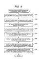
- a step (will be abbreviated as "S" hereinafter) 101 necessary parameters are read. That is, the vehicle speeds ⁇ fl, ⁇ fr, ⁇ rl, ⁇ rr derived from the vehicle wheel speed sensors 51fl, 51fr, 51rl, 51rr are read; the steering wheel angle " ⁇ H" derived from the steering wheel angle sensor 53 is read; the actual lateral acceleration (d 2 y/dt 2 ) derived from the lateral acceleration sensor 53 is read; the actual front/rear acceleration (d 2 xe/dt 2 ) derived from the front/rear acceleration sensor 54 is read; and also, the actual Yaw rate " ⁇ " derived from the yaw rate sensor 55 is read.
- the driving force distribution control operation is advanced to an S102 in which the necessary parameters are calculated.
- the lateral acceleration/steering wheel angle gain "Gy” is calculated by the lateral acceleration/steering wheel angle gain calculating unit 62;
- the vehicle speed "V” is calculated by the vehicle speed calculating unit 61;
- the reference lateral acceleration (d 2 yr/dt 2 ) is calculated by the reference lateral acceleration calculating unit 63;
- the basic addition yaw moment "Mz ⁇ " is calculated by the basic addition yaw moment setting unit 64.
- the calculation of the basic addition yaw moment "Mz ⁇ " is carried out by a basic addition yaw moment setting routine (will be explained later) shown in Fig. 8.
- the control operation is advanced to S103 in which a front/rear driving force distribution cooperative control operation (will be explained in Fig. 9) is executed. Then, the control operation is advanced to S104 in which a right/left driving force distribution cooperation control operation (will be explained in Fig. 10) is executed, and thereafter, the present control operation program is returned.
- the above-explained basic addition yaw moment setting routine is executed as follows. That is, in S201, the yaw rate/steering wheel angle gain calculating unit 64b first calculates a yaw rate/steering wheel angle gain "Gy.”
- the setting routine program is advanced to S202 in which the yaw rate sensitive gain calculating unit 64c calculates a yaw rate sensitive gain "K ⁇ .”
- the setting routine program is advanced to S203 in which the lateral acceleration deviation sensitive gain calculating unit 64d calculates a lateral acceleration deviation sensitive gain "Ky.”
- the setting routine program is advanced to S204 in which the lateral acceleration deviation calculating unit 64a calculates a lateral acceleration deviation (d 2 ye/dt 2 ).
- the setting routine program is advanced to S205 in which the basic addition yaw moment calculating unit 64e calculates basic addition yaw moment "Mz ⁇ ", and thus, outputs the calculated basic addition yaw moment "Mz ⁇ .” Thereafter, the basic addition yaw moment setting routine is returned to the main control program.
- the low-speed-drive vehicle speed sensitive gain setting unit 66a sets a low-speed-drive vehicle speed sensitive gain "KVvl.”
- the cooperative control operation is advanced to S302 in which the vehicle body skid angular velocity calculating unit 66b calculates vehicle body skid angular velocity (d ⁇ /dt).
- the cooperative control operation is advanced to S303 in which the vehicle body skid angular velocity gain setting unit 66c sets a vehicle body skid angular velocity sensitive gain KV(d ⁇ /dt).
- the cooperative control operation is advanced to S305 in which the front/rear driving force distribution control addition yaw moment calculating unit 66e calculates the front/rear driving force distribution control addition yaw moment "MVz ⁇ .”
- the cooperative control operation is advanced to S306 in which the front/rear driving force distribution cooperative control gain calculating unit 67 calculates a front/rear driving force distribution cooperative control gain "KcV.”
- the cooperative control operation is advanced to S307 in which the front/rear driving force distribution cooperative control addition yaw moment calculating unit 68 calculates front/rear driving force distribution cooperative control addition yaw moment "MVz ⁇ c.”
- the cooperative control operation is advanced to S308 in which the transfer clutch torque converting control unit 69 converts the front/rear driving force distribution cooperative control addition yaw moment "MVz ⁇ c" into transfer clutch torque "TLSDV", and thus, outputs this converted transfer clutch torque "TLSDV” to the transfer clutch torque driving unit 80.
- the assist amount determining gain setting unit 70b sets an assist amount determining gain "KYz ⁇ .”
- the cooperative control operation is advanced to S404 in which the right/left driving force distribution cooperative control gain calculating unit 71 calculates a right/left driving force distribution cooperative control gain "KcY.”
- the cooperative control operation is advanced to S405 in which the right/left driving force distribution cooperative control addition yaw moment calculating unit 72 calculates right/left driving force distribution cooperative control addition yaw moment "MYz ⁇ c.”
- the cooperative control operation is advanced to S406 in which the rear clutch torque converting control unit 73 converts the right/left driving force distribution cooperative control addition yaw moment "MYz ⁇ c" into rear clutch torque "TRY”, and thus, outputs this converted rear clutch torque "TRY” to the rear clutch torque driving unit 90. Thereafter, this cooperative control operation is returned to the main control program.
- both the front/rear driving force distribution control operation and the right/left driving force distribution control operation are carried out under the normal condition.
- the right/left driving force distribution control operation is carried out under the normal condition.
- the front/rear driving force distribution control operation in view of the turning round characteristic is carried out in such a manner that the driving force is distributed to the rear wheel side.
- the right/left driving force distribution control operation is carried out under the normal condition, when the right/left driving force distraction control operation is carried out, the slip ratio of the rear inner wheel is decreased, depending upon the torque distribution of the turning round direction, and in some cases, the gripping effect of the rear inner wheel along the lateral direction is recovered, so that the desirable moment cannot be added. As a consequence, the control amount of the right/left driving force distribution control operation is decreased.
- both the front/rear driving force distribution control operation and the right/left driving force distribution control operation can be properly actuated while the maximum effects can be achieved in the various traveling scenes of the vehicle. As a consequence, both the stability and the turning around characteristic of the vehicle can be maintained under the optimum conditions.
Applications Claiming Priority (1)
| Application Number | Priority Date | Filing Date | Title |
|---|---|---|---|
| JP2004307184A JP4684618B2 (ja) | 2004-10-21 | 2004-10-21 | 車両の駆動力配分制御装置 |
Publications (3)
| Publication Number | Publication Date |
|---|---|
| EP1650072A2 true EP1650072A2 (de) | 2006-04-26 |
| EP1650072A3 EP1650072A3 (de) | 2007-12-12 |
| EP1650072B1 EP1650072B1 (de) | 2009-12-09 |
Family
ID=35583413
Family Applications (1)
| Application Number | Title | Priority Date | Filing Date |
|---|---|---|---|
| EP05023067A Active EP1650072B1 (de) | 2004-10-21 | 2005-10-21 | Antriebskraftverteilungs- Steuerungsgerät für Fahrzeuge |
Country Status (4)
| Country | Link |
|---|---|
| US (1) | US7607506B2 (de) |
| EP (1) | EP1650072B1 (de) |
| JP (1) | JP4684618B2 (de) |
| DE (1) | DE602005018148D1 (de) |
Cited By (3)
| Publication number | Priority date | Publication date | Assignee | Title |
|---|---|---|---|---|
| WO2015130204A1 (en) * | 2014-02-27 | 2015-09-03 | Borgwarner Torqtransfer Systems Ab | A torque vectoring device |
| US9751401B2 (en) | 2006-02-24 | 2017-09-05 | Stiliyan Tsonev Ganchev | System for controlling torque distribution |
| EP3511219A1 (de) * | 2012-10-01 | 2019-07-17 | Hitachi Automotive Systems, Ltd. | Bewegungssteuerungsvorrichtung für ein fahrzeug |
Families Citing this family (12)
| Publication number | Priority date | Publication date | Assignee | Title |
|---|---|---|---|---|
| JP4980168B2 (ja) | 2007-08-01 | 2012-07-18 | 富士重工業株式会社 | 車両挙動制御装置 |
| JP4973415B2 (ja) * | 2007-09-24 | 2012-07-11 | トヨタ自動車株式会社 | 車両の駆動力配分制御装置 |
| JP5282615B2 (ja) * | 2009-03-16 | 2013-09-04 | トヨタ自動車株式会社 | 車両運動制御システム |
| JP5948738B2 (ja) * | 2011-05-31 | 2016-07-06 | 日産自動車株式会社 | 制駆動力制御装置および制駆動力制御方法 |
| JP5658717B2 (ja) * | 2012-08-09 | 2015-01-28 | 富士重工業株式会社 | 4輪駆動車の制御装置 |
| JP6416574B2 (ja) * | 2014-09-29 | 2018-10-31 | 日立オートモティブシステムズ株式会社 | 車両の制御方法、車両制御システム、車両制御装置、および制御プログラム |
| DE102017219271A1 (de) * | 2017-10-26 | 2019-05-02 | Deere & Company | Verfahren zum Betreiben eines Nutzfahrzeugs mit Allradantrieb und Differentialsperre |
| KR102530684B1 (ko) * | 2018-05-04 | 2023-05-11 | 현대자동차주식회사 | 차량의 드리프트 주행 상태 구현 제어 방법 |
| US11801866B2 (en) | 2021-09-29 | 2023-10-31 | Canoo Technologies Inc. | Emergency motion control for vehicle using steering and torque vectoring |
| US11845422B2 (en) | 2021-09-29 | 2023-12-19 | Canoo Technologies Inc. | Path tracking control for self-driving of vehicle with yaw moment distribution |
| US11845465B2 (en) | 2021-09-29 | 2023-12-19 | Canoo Technologies Inc. | Autonomous lateral control of vehicle using direct yaw moment control |
| WO2023107764A1 (en) * | 2021-12-08 | 2023-06-15 | Canoo Technologies Inc. | Vehicle motion control using torque vectoring with consideration of driver intent and load transfer |
Citations (2)
| Publication number | Priority date | Publication date | Assignee | Title |
|---|---|---|---|---|
| JPH07108840A (ja) | 1993-10-14 | 1995-04-25 | Mitsubishi Motors Corp | 車両用左右輪間トルク移動制御装置 |
| JPH11263140A (ja) | 1998-03-19 | 1999-09-28 | Fuji Heavy Ind Ltd | 車両用左右駆動力配分装置 |
Family Cites Families (15)
| Publication number | Priority date | Publication date | Assignee | Title |
|---|---|---|---|---|
| JPH0811493B2 (ja) * | 1986-12-16 | 1996-02-07 | 日本電装株式会社 | 四輪駆動車の駆動力制御装置 |
| JP3221873B2 (ja) * | 1990-04-20 | 2001-10-22 | マツダ株式会社 | 4輪駆動車のトルク配分制御装置 |
| JPH0424154A (ja) * | 1990-05-15 | 1992-01-28 | Mazda Motor Corp | 4輪駆動車のトルク配分制御装置 |
| US5259476A (en) * | 1991-04-26 | 1993-11-09 | Fuji Jukogyo Kabushiki Kaisha | Torque distribution control system for a four-wheel drive motor vehicle |
| JP3144717B2 (ja) * | 1992-09-17 | 2001-03-12 | 富士重工業株式会社 | 4輪駆動車のトルク配分制御方法 |
| JP3268124B2 (ja) * | 1994-06-27 | 2002-03-25 | 富士重工業株式会社 | 車両のトルク配分制御装置 |
| JPH111129A (ja) * | 1997-06-11 | 1999-01-06 | Fuji Heavy Ind Ltd | 4輪駆動車のスリップ制御装置 |
| US6415215B1 (en) * | 2000-02-23 | 2002-07-02 | Koyo Seiko Co., Ltd. | Vehicle attitude control apparatus |
| JP4237378B2 (ja) * | 2000-06-29 | 2009-03-11 | 富士重工業株式会社 | 車両の駆動力伝達制御装置 |
| JP3719116B2 (ja) * | 2000-08-30 | 2005-11-24 | トヨタ自動車株式会社 | 車輌の駆動力制御装置 |
| DE10245035A1 (de) | 2002-09-26 | 2004-04-08 | Dr.Ing.H.C. F. Porsche Ag | Verfahren zur Regelung des Fahrverhaltens mittels Einflussnahme zur Vermeidung des Untersteuerns |
| JP4657594B2 (ja) * | 2003-10-07 | 2011-03-23 | 富士重工業株式会社 | 車両運動制御装置 |
| JP4267495B2 (ja) * | 2004-03-31 | 2009-05-27 | 本田技研工業株式会社 | 4輪駆動車両の駆動力制御方法 |
| JP4554252B2 (ja) * | 2004-03-31 | 2010-09-29 | 本田技研工業株式会社 | 4輪駆動車両の制御方法 |
| JP4980168B2 (ja) * | 2007-08-01 | 2012-07-18 | 富士重工業株式会社 | 車両挙動制御装置 |
-
2004
- 2004-10-21 JP JP2004307184A patent/JP4684618B2/ja not_active Expired - Fee Related
-
2005
- 2005-10-21 DE DE602005018148T patent/DE602005018148D1/de active Active
- 2005-10-21 EP EP05023067A patent/EP1650072B1/de active Active
- 2005-10-21 US US11/254,889 patent/US7607506B2/en not_active Expired - Fee Related
Patent Citations (2)
| Publication number | Priority date | Publication date | Assignee | Title |
|---|---|---|---|---|
| JPH07108840A (ja) | 1993-10-14 | 1995-04-25 | Mitsubishi Motors Corp | 車両用左右輪間トルク移動制御装置 |
| JPH11263140A (ja) | 1998-03-19 | 1999-09-28 | Fuji Heavy Ind Ltd | 車両用左右駆動力配分装置 |
Cited By (3)
| Publication number | Priority date | Publication date | Assignee | Title |
|---|---|---|---|---|
| US9751401B2 (en) | 2006-02-24 | 2017-09-05 | Stiliyan Tsonev Ganchev | System for controlling torque distribution |
| EP3511219A1 (de) * | 2012-10-01 | 2019-07-17 | Hitachi Automotive Systems, Ltd. | Bewegungssteuerungsvorrichtung für ein fahrzeug |
| WO2015130204A1 (en) * | 2014-02-27 | 2015-09-03 | Borgwarner Torqtransfer Systems Ab | A torque vectoring device |
Also Published As
| Publication number | Publication date |
|---|---|
| US20060086556A1 (en) | 2006-04-27 |
| EP1650072B1 (de) | 2009-12-09 |
| US7607506B2 (en) | 2009-10-27 |
| DE602005018148D1 (de) | 2010-01-21 |
| EP1650072A3 (de) | 2007-12-12 |
| JP4684618B2 (ja) | 2011-05-18 |
| JP2006117113A (ja) | 2006-05-11 |
Similar Documents
| Publication | Publication Date | Title |
|---|---|---|
| EP1650072B1 (de) | Antriebskraftverteilungs- Steuerungsgerät für Fahrzeuge | |
| EP0963892B1 (de) | Drehmomentverteilungsregelsystem für ein allradgetriebenes Fahrzeug | |
| EP1197410B1 (de) | Vorrichtung und Verfahren zur Regelung des Fahrverhaltens eines Fahrzeuges | |
| EP1203688B1 (de) | Antriebskraftverteilungssystem eines Fahrzeugs | |
| EP1686031B1 (de) | Steuervorrichtung eines Fahrzeuges mit Allradantrieb | |
| EP0911205B1 (de) | Steuerungssystem für die Grenzkraft eines Differentials in einem vierradangetriebenen Fahrzeug | |
| JP3409439B2 (ja) | 左右輪と前後輪の駆動力配分総合制御装置 | |
| JP4082549B2 (ja) | 四輪駆動車両の駆動力制御装置 | |
| US20060041364A1 (en) | Vehicle behavior control device | |
| EP1731347B1 (de) | Front- und Heckantriebs- Verteilungssteuerungssystem für ein Fahrzeug | |
| US10967735B2 (en) | Control device for four-wheel drive vehicle | |
| JP4215861B2 (ja) | 4輪駆動車の動力配分制御装置 | |
| US8055420B2 (en) | Vehicle control device | |
| EP3747669B1 (de) | Fahrzeugausrichtungsteuerungssystem | |
| JP5154397B2 (ja) | 車両運動制御装置 | |
| EP1731349A1 (de) | Antriebsverteilungssytem für Fahrzeuge mit Vorder- und Hinterradantrieb | |
| JP3470505B2 (ja) | 自動変速機の変速制御装置 | |
| US9592825B2 (en) | Vehicle control system | |
| EP1522474B1 (de) | Vorrichtung zur Regelung der Fahrzeugbewegung | |
| EP1731348A2 (de) | Fahrzeugs- Antriebskraft- Verteilungssteuerungssystem | |
| EP1500547A1 (de) | Vorrichtung und verfahren zur steuerung der verteilung von antriebskraft eines kraftfahrzeugs mit vierradantrieb | |
| JP4519216B2 (ja) | 車両運動制御装置 | |
| JP4668563B2 (ja) | 車両の駆動力配分制御装置 | |
| JP2001071776A (ja) | 差動制限制御方法および制御装置 | |
| JP2700321B2 (ja) | トルクスプリット型4輪駆動4輪操舵車 |
Legal Events
| Date | Code | Title | Description |
|---|---|---|---|
| PUAI | Public reference made under article 153(3) epc to a published international application that has entered the european phase |
Free format text: ORIGINAL CODE: 0009012 |
|
| AK | Designated contracting states |
Kind code of ref document: A2 Designated state(s): AT BE BG CH CY CZ DE DK EE ES FI FR GB GR HU IE IS IT LI LT LU LV MC NL PL PT RO SE SI SK TR |
|
| AX | Request for extension of the european patent |
Extension state: AL BA HR MK YU |
|
| PUAL | Search report despatched |
Free format text: ORIGINAL CODE: 0009013 |
|
| AK | Designated contracting states |
Kind code of ref document: A3 Designated state(s): AT BE BG CH CY CZ DE DK EE ES FI FR GB GR HU IE IS IT LI LT LU LV MC NL PL PT RO SE SI SK TR |
|
| AX | Request for extension of the european patent |
Extension state: AL BA HR MK YU |
|
| RIC1 | Information provided on ipc code assigned before grant |
Ipc: B60K 23/04 20060101ALI20071107BHEP Ipc: B60K 23/08 20060101AFI20060125BHEP |
|
| 17P | Request for examination filed |
Effective date: 20080529 |
|
| AKX | Designation fees paid |
Designated state(s): DE |
|
| GRAP | Despatch of communication of intention to grant a patent |
Free format text: ORIGINAL CODE: EPIDOSNIGR1 |
|
| GRAS | Grant fee paid |
Free format text: ORIGINAL CODE: EPIDOSNIGR3 |
|
| GRAA | (expected) grant |
Free format text: ORIGINAL CODE: 0009210 |
|
| AK | Designated contracting states |
Kind code of ref document: B1 Designated state(s): DE |
|
| REF | Corresponds to: |
Ref document number: 602005018148 Country of ref document: DE Date of ref document: 20100121 Kind code of ref document: P |
|
| PLBE | No opposition filed within time limit |
Free format text: ORIGINAL CODE: 0009261 |
|
| STAA | Information on the status of an ep patent application or granted ep patent |
Free format text: STATUS: NO OPPOSITION FILED WITHIN TIME LIMIT |
|
| 26N | No opposition filed |
Effective date: 20100910 |
|
| REG | Reference to a national code |
Ref country code: DE Ref legal event code: R082 Ref document number: 602005018148 Country of ref document: DE Representative=s name: VOSSIUS & PARTNER PATENTANWAELTE RECHTSANWAELT, DE Ref country code: DE Ref legal event code: R081 Ref document number: 602005018148 Country of ref document: DE Owner name: SUBARU CORPORATION, JP Free format text: FORMER OWNER: FUJI JUKOGYO K.K., TOKIO/TOKYO, JP |
|
| REG | Reference to a national code |
Ref country code: DE Ref legal event code: R084 Ref document number: 602005018148 Country of ref document: DE |
|
| PGFP | Annual fee paid to national office [announced via postgrant information from national office to epo] |
Ref country code: DE Payment date: 20220620 Year of fee payment: 18 |