EP1649471B1 - Procede continu de fabrication de cables electriques - Google Patents
Procede continu de fabrication de cables electriques Download PDFInfo
- Publication number
- EP1649471B1 EP1649471B1 EP03817932.1A EP03817932A EP1649471B1 EP 1649471 B1 EP1649471 B1 EP 1649471B1 EP 03817932 A EP03817932 A EP 03817932A EP 1649471 B1 EP1649471 B1 EP 1649471B1
- Authority
- EP
- European Patent Office
- Prior art keywords
- layer
- cable
- phase
- conductor
- process according
- Prior art date
- Legal status (The legal status is an assumption and is not a legal conclusion. Google has not performed a legal analysis and makes no representation as to the accuracy of the status listed.)
- Expired - Lifetime
Links
Images


Classifications
-
- H—ELECTRICITY
- H01—ELECTRIC ELEMENTS
- H01B—CABLES; CONDUCTORS; INSULATORS; SELECTION OF MATERIALS FOR THEIR CONDUCTIVE, INSULATING OR DIELECTRIC PROPERTIES
- H01B13/00—Apparatus or processes specially adapted for manufacturing conductors or cables
- H01B13/22—Sheathing; Armouring; Screening; Applying other protective layers
- H01B13/26—Sheathing; Armouring; Screening; Applying other protective layers by winding, braiding or longitudinal lapping
- H01B13/2613—Sheathing; Armouring; Screening; Applying other protective layers by winding, braiding or longitudinal lapping by longitudinal lapping
- H01B13/2626—Sheathing; Armouring; Screening; Applying other protective layers by winding, braiding or longitudinal lapping by longitudinal lapping of a coaxial cable outer conductor
-
- H—ELECTRICITY
- H01—ELECTRIC ELEMENTS
- H01B—CABLES; CONDUCTORS; INSULATORS; SELECTION OF MATERIALS FOR THEIR CONDUCTIVE, INSULATING OR DIELECTRIC PROPERTIES
- H01B13/00—Apparatus or processes specially adapted for manufacturing conductors or cables
-
- H—ELECTRICITY
- H01—ELECTRIC ELEMENTS
- H01B—CABLES; CONDUCTORS; INSULATORS; SELECTION OF MATERIALS FOR THEIR CONDUCTIVE, INSULATING OR DIELECTRIC PROPERTIES
- H01B13/00—Apparatus or processes specially adapted for manufacturing conductors or cables
- H01B13/0003—Apparatus or processes specially adapted for manufacturing conductors or cables for feeding conductors or cables
-
- H—ELECTRICITY
- H01—ELECTRIC ELEMENTS
- H01B—CABLES; CONDUCTORS; INSULATORS; SELECTION OF MATERIALS FOR THEIR CONDUCTIVE, INSULATING OR DIELECTRIC PROPERTIES
- H01B13/00—Apparatus or processes specially adapted for manufacturing conductors or cables
- H01B13/06—Insulating conductors or cables
- H01B13/14—Insulating conductors or cables by extrusion
-
- H—ELECTRICITY
- H01—ELECTRIC ELEMENTS
- H01B—CABLES; CONDUCTORS; INSULATORS; SELECTION OF MATERIALS FOR THEIR CONDUCTIVE, INSULATING OR DIELECTRIC PROPERTIES
- H01B13/00—Apparatus or processes specially adapted for manufacturing conductors or cables
- H01B13/22—Sheathing; Armouring; Screening; Applying other protective layers
- H01B13/26—Sheathing; Armouring; Screening; Applying other protective layers by winding, braiding or longitudinal lapping
- H01B13/2613—Sheathing; Armouring; Screening; Applying other protective layers by winding, braiding or longitudinal lapping by longitudinal lapping
- H01B13/262—Sheathing; Armouring; Screening; Applying other protective layers by winding, braiding or longitudinal lapping by longitudinal lapping of an outer metallic screen
-
- H—ELECTRICITY
- H01—ELECTRIC ELEMENTS
- H01B—CABLES; CONDUCTORS; INSULATORS; SELECTION OF MATERIALS FOR THEIR CONDUCTIVE, INSULATING OR DIELECTRIC PROPERTIES
- H01B7/00—Insulated conductors or cables characterised by their form
- H01B7/17—Protection against damage caused by external factors, e.g. sheaths or armouring
- H01B7/18—Protection against damage caused by wear, mechanical force or pressure; Sheaths; Armouring
- H01B7/189—Radial force absorbing layers providing a cushioning effect
-
- H—ELECTRICITY
- H01—ELECTRIC ELEMENTS
- H01B—CABLES; CONDUCTORS; INSULATORS; SELECTION OF MATERIALS FOR THEIR CONDUCTIVE, INSULATING OR DIELECTRIC PROPERTIES
- H01B9/00—Power cables
- H01B9/02—Power cables with screens or conductive layers, e.g. for avoiding large potential gradients
- H01B9/027—Power cables with screens or conductive layers, e.g. for avoiding large potential gradients composed of semi-conducting layers
Definitions
- the present invention relates to a process for manufacturing electrical cables, in particular electrical cables for power transmission or distribution at medium or high voltage.
- medium voltage is used to refer to a tension typically from about 1 kV to about 60 kV and the term high voltage refers to a tension above 60 kV (very high voltage is also sometimes used in the art to define voltages greater than about 150 kV or 220 kV, up to 500 kV or more).
- Said cables may be used for both direct current (DC) or alternating current (AC) transmission or distribution.
- Cables for power transmission or distribution at medium or high voltage generally have a metal conductor which is surrounded, respectively, with a first inner semiconductive layer, an insulating layer and an outer semiconductive layer.
- a metal conductor which is surrounded, respectively, with a first inner semiconductive layer, an insulating layer and an outer semiconductive layer.
- the cable In a position radially external to said core, the cable is provided with a metal shield (or screen), usually of aluminium, lead or copper.
- the metal shield may consist of a number of metal wires or tapes, helically wound around the core, or of a circumferentially continuous tube, such as a metallic tape shaped according to a tubular form and welded or sealed to ensure hermeticity.
- the metal shield performs an electrical function by creating, inside the cable, as a result of direct contact between the metal shield and the outer semiconductive layer of the core, a uniform electrical field of the radial type, at the same time cancelling the external electrical field of the cable.
- a further function is that of withstanding short-circuit currents.
- the metal shield When made in circumferentially continuous tubular form, the metal shield also provides hermeticity against water penetration in the radical direction.
- said cable further comprises a polymeric oversheath in a position radially external to the metal shield mentioned above.
- cables for power transmission or distribution are generally provided with one or more layers for protecting said cables from accidental impacts which may occur on their external surface.
- Accidental impacts oil a cable may occur, for example, during transport thereof or during the laying step of the cable in a trench dug into the soil. Said accidental impact may cause a series of structural damages to the cable, including deformation of the insulating layer and detachment of the insulating layer from the semiconductive layers, damages which may cause variations in the electrical voltage stress of the insulating layer with a consequent decrease in the insulating capacity of said layer.
- Cross-linked insulation cables are known and their manufacturing process is described, for example, in EP1288218 , EP426073 , US2002/0143114 , and US4469539 .
- the cross-linking of the cable insulation can be made either by using the so-called silane cross-linking or by using peroxides.
- the cable core comprising the extruded insulation surrounding the conductor, is maintained for a relatively long period of time (hours or days) in a water-containing ambient (either liquid or vapor, such as ambient humidity), such that the water can diffuse through the insulation to cause the cross-linking to take place.
- a water-containing ambient either liquid or vapor, such as ambient humidity
- the cross-linking is caused by the decomposition of a peroxide, at relatively high temperature and pressure.
- the chemical reactions that take place generate gaseous byproducts which must be allowed to diffuse through the insulation layer not only during the curing time but also after the curing. Therefore a degassing step has to be provided during which the cable core is stored for a period of time sufficient to eliminate such gaseous byproducts before further layers are applied over the cable core (in particular in case such layers are gas-tight or substantially gas-tight, such as in the case a longitudinally folded metal layer is applied).
- the gaseous byproducts e.g. methane, acetophenone, cuminic alcohol
- the gaseous byproducts e.g. methane, acetophenone, cuminic alcohol
- the methane are inflammable and thus explosions may occur, for instance during laying or joining of said cables in the trench dug into the soil.
- porosity in the insulation is found which can deteriorate the insulation electric properties.
- thermoplastic insulation A process for producing a cable having thermoplastic insulation is described in WO02/47092 , in the name of the same Applicant, where a cable is produced by extruding and passing through a static mixer a thermoplastic material, comprising a thermoplastic polymer mixed with a dielectric liquid, such thermoplastic material being applied around a conductor by means of an extrusion head. After a cooling and a drying step, the cable core is stored on a reel and then a metal shield is applied by helically placing thin strips of copper or copper wires onto the cable core. An outer polymer sheath then completes the cable.
- the shield was of a type only suitable for a non-continuous application process since it required the use of spools mounted on a rotating apparatus, as further explained in the following.
- the Applicant has perceived that the presence of a rest phase during the cable production, for example for curing or degassing purposes, is undesirable because it limits the length of each cable piece (storage on cable reels being required), it introduces space and logistic problems in the factory, it extends the cable manufacturing time and, finally, it increases the cost of the cable production.
- a cable can be produced in a particularly convenient manner by a continuous process, i.e. in the absence of intermediate resting or storage phases, by using a thermoplastic insulation material in combination with a longitudinally folded, circumferentially continuous metal shield.
- the present invention refers to a continuous process for manufacturing an electric cable, said process comprising the phases of:
- the circumferentially closed metal shield around the extruded insulating layer is formed by longitudinally folding a metal sheet, either having overlapping edges or edge-bonded edges.
- the phase of forming the metal shield according to the process of the present invention comprises the step of overlapping the edges of a mental sheet.
- said phase of forming comprises the step of bonding the edges of said metal sheet.
- the process comprises the phase of supplying the conductor in the form of a metal rod.
- the process of the present invention comprises the phase of applying an impact protecting element around the metal shield.
- said impact protecting element is applied by extrusion.
- said impact protecting element comprises a non-expanded polymeric layer and an expanded polymeric layer.
- the expanded polymeric layer is positioned radially external to the non-expanded polymeric layer.
- the non-expanded polymeric layer and the expanded polymeric layer are applied by co-extrusion.
- the process of the invention generally further comprises the phase of applying an oversheath around the metal shield.
- the oversheath is applied by extrusion.
- the impact protecting element is applied between the closed metal shield and the oversheath.
- thermoplastic polymer material of the insulating layer includes a predetermined amount of a dielectric liquid.
- the Applicant has found that the cable obtained by the continuous process of the present invention is surprisingly provided with high mechanical resistance to accidental impacts which may occur on the cable.
- the Applicant has found that a high impact protection is advantageously conferred to the cable by combining a circumferentially closed metal shield with an impact protecting element comprising at least one expanded polymeric layer, the latter being located radially external to the metal shield.
- the Applicant has noticed that, in case a deformation of the shield occurs due to a relevant impact on the cable, the presence of a circumferentially closed metal shield is particularly advantageous since the shield deforms continuously and smoothly, thereby avoiding any local increases of the electric field in the insulating layer. Moreover, the Applicant has found that a cable provided with a thermoplastic insulating layer, a circumferentially closed metal shield and an impact protecting element comprising at least one expanded polymeric layer can be advantageously obtained by means of a continuous manufacturing process.
- the Applicant has found that the mechanical resistance to accidental impacts can be advantageously increased by providing the cable with a further expanded polymeric layer in a position radially internal with respect to the metal shield.
- said further expanded polymeric layer is a water-blocking layer.
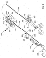
- Figures 1 , 2 show a perspective view, partially in cross section, of an electrical cable 1, typically designed for use in medium or high voltage range, which is made with the process according to the present invention.
- the cable 1 comprises: a conductor 2; an inner semiconductive layer 3; an insulating layer 4; an outer semiconductive layer 5; a metal shield 6 and a protective element 20.
- the conductor 2 is a metal rod.
- the conductor is made of copper or aluminium.
- the conductor 2 comprises at least two metal wires, preferably of copper or aluminium, which are stranded together according to conventional techniques.
- the cross sectional area of the conductor 2 is determined in relationship with the power to be transported at the selected voltage.
- Preferred cross sectional areas for cables according to the present invention range from 16 mm 2 to 1,600 mm 2 .
- the term "insulating material” is used to indicate a material having a dielectric rigidity of at least 5 kV/mm, preferably greater than 10 kV/mm.
- the insulating material has a dielectric rigidity greater than 40 kV/mm.
- the insulating layer of power transmission cables has a dielectric constant (K) of greater than 2.
- the inner semiconductive layer 3 and the outer semiconductive layer 5 are generally obtained by extrusion.
- the base polymeric materials of the semiconductive layers 3, 5, which are conveniently selected from those mentioned in the following of the present description with reference to the expanded polymeric layer, are additivated with an electroconductive carbon black, for example electroconductive furnace black or acetylene black, so as to confer semiconductive properties to the polymer material.
- an electroconductive carbon black for example electroconductive furnace black or acetylene black
- the surface area of the carbon black is generally greater than 20 m 2 /g, usually between 40 and 500 m 2 /g.
- a highly conducting carbon black may be used, having a surface area of at least 900 m 2 /g, such as, for example, the furnace carbon black known commercially under the tradename Ketjenblack® EC (Akzo Chemie NV).
- the amount of carbon black to be added to the polymer matrix can vary depending on the type of polymer and of carbon black used, the degree of expansion which it is intended to obtain, the expanding agent, etc.
- the amount of carbon black thus has to be such as to give the expanded material sufficient semiconductive properties, in particular such as to obtain a volumetric resistivity value for the expanded material, at room temperature, of less than 500 ⁇ m, preferably less than 20 ⁇ m.
- the amount of carbon black can range between 1 and 50% by weight, preferably between 3 and 30% by weight, relative to the weight of the polymer.
- the inner and outer semiconductive layers 3, 5 comprise a non-crosslinked polymeric material, more preferably a polypropylene material.
- the insulating layer 4 is made of a thermoplastic material which comprises a thermoplastic polymer material including a predetermined amount of a dielectric liquid.
- thermoplastic polymer material is selected from: polyolefins, copolymers of different olefins, copolymers of an olefin with an ethylenically unsaturated ester, polyesters, polyacetates, cellulose polymers, polycarbonates, polysulphones, phenol resins, urea resins, polyketones, polyacrylates, polyamides, polyamines, and mixtures thereof.
- polyethylene in particular low density PE (LDPE), medium density PE (MDPE), high density PE (HDPE), linear low density PE (LLDPE), ultra-low density polyethylene (ULDPE); polypropylene (PP); ethylene/vinyl ester copolymers, for example ethylene/vinyl acetate (EVA); ethylene/acrylate copolymers, in particular ethylene/methyl acrylate (EMA), ethylene/ethyl acrylate (EEA) and ethylene/butyl acrylate (EBA); ethylene/ ⁇ -olefin thermoplastic copolymers; polystyrene; acrylonitrile/butadiene/styrene (ABS) resins; halogenated polymers, in particular polyvinyl chloride (PVC); polyurethane (PUR); polyamides; aromatic polyesters such as polyethylene terephthalate (PET) or polybutylene terephthalate (PBT); and copolymers thereof or mechanical
- the dielectric liquid can be selected from: mineral oils such as, for example, naphthenic oils, aromatic oils, paraffinic oils, polyaromatic oils, said mineral oils optionally containing at least one heteroatom selected from oxygen, nitrogen or sulphur; liquid paraffins; vegetable oils such as, for example, soybean oil, linseed oil, castor oil; oligomeric aromatic polyolefins; paraffinic waxes such as, for example, polyethylene waxes, polypropylene waxes; synthetic oils such as, for example, silicone oils, alkyl benzenes (such as, for example, dibenzyltoluene, dodecylbenzene, di(octylbenzyl)toluene), aliphatic esters (such as, for example, tetraesters of pentaerythritol, esters of sebacic acid, phthalic esters), olefin oligomers (such as, for example, optionally hydrogenated
- the metal shield 6 is made of a continuous metal sheet, preferably of aluminium or copper, which is shaped as a tube.
- the metal sheet forming the metal shield 6 is folded lengthwise around the outer semiconductive layer 5 with overlapping edges. Conveniently, a sealing and bonding material is interposed between the overlapping edges, so as to make the metal shield watertight. Alternatively, the metal sheet edges may be welded.
- the metal shield 6 is surrounded by an oversheath 23 preferably made of a non-crosslinked polymer material; for example polyvinyl chloride (PVC) or polyethylene (PE); the thickness of such oversheath can be selected to provide the cable with a certain degree of resistance to mechanical stresses and impacts, however without excessively increasing the cable diameter and rigidity.
- PVC polyvinyl chloride
- PE polyethylene
- Such solution is convenient, for example, for cables intended for use in protected areas, where limited impacts are expected or protection is otherwise provided.
- the cable 1 is provided with a protective element 20, located in a position radially external to said metal shield 6.
- the protective element 20 comprises a non-expanded polymeric layer 21 (in a radial internal position) and an expanded polymeric layer 22 (in a radial external position).
- the non-expanded polymeric layer 21 is in contact with the metal shield 6 and the expanded polymeric layer 22 is between the non-expanded polymeric layer 21 and the polymeric oversheath 23.
- the thickness of the non-expanded polymeric layer 21 is in the range of from 0.5 mm to 5 mm.
- the thickness of the expanded polymeric layer 22 is in the range of from 0.5 mm to 6 mm.
- the thickness of the expanded polymeric layer 22 is from 1 to two times the thickness of the non-expanded polymeric layer 21.
- the protective element 20 has the function of providing enhanced protection to the cable from external impacts, by at least partially absorbing the impact energy.
- the expandable polymeric material which is suitable for being used in the expanded polymeric layer 22 can be selected from the group comprising: polyolefins, copolymers of different olefins, copolymers of an olefin with an ethylenically unsaturated ester, polyesters, polycarbonates, polysulphones, phenol resins, urea resins, and mixtures thereof.
- polyethylene in particular low density PE (LDPE), medium density PE (MDPE), high density PE (HDPE), linear low density PE (LLDPE), ultra-low density polyethylene (ULDPE); polypropylene (PP); elastomeric ethylene/propylene copolymers (EPR) or ethylene/propylene/diene terpolymers (EPDM); natural rubber; butyl rubber; ethylene/vinyl ester copolymers, for example ethylene/vinyl acetate (EVA); ethylene/acrylate copolymers, in particular ethylene/methyl acrylate (EMA), ethylene/ethyl acrylate (EEA) and ethylene/butyl acrylate (EBA); ethylene/ ⁇ -olefin thermoplastic copolymers; polystyrene; acrylonitrile/butadiene/styrene (ABS) resins; halogenated polymers, in particular polyvinyl chloride (PVO); polyurethane
- the polymeric material forming the expanded polymeric layer 22 is a polyolefin polymer or copolymer based on methylene and/or propylene, and is selected in particular from:
- the commercial products Elvax ® (DuPont), Levapren ® (Bayer) and Lotryl ® (Elf-Atochem) are in class (a)
- products Dutral ® (Enichem) or Nordel ® (Dow-DuPont) are in class (b)
- products belonging to class (c) are Engage ® (Dow-DuPont) or Exact ® (Exxon)
- polypropylene modified with ethylene/alpha-olefin copolymers (d) are commercially available under the brand names Moplen ® or Hifax ® (Basell), or also Fina-Pro ® (Fina), and the like.
- thermoplastic elastomers comprising a continuous matrix of a thermoplastic polymer, e.g. polypropylene, and fine particles (generally having a diameter of the order of 1 ⁇ m - 10 ⁇ m) of a cured elastomeric polymer, e.g. crosslinked EPR o EPDM, dispersed in the thermoplastic matrix.
- a thermoplastic polymer e.g. polypropylene
- fine particles generally having a diameter of the order of 1 ⁇ m - 10 ⁇ m
- a cured elastomeric polymer e.g. crosslinked EPR o EPDM
- the elastomeric polymer may be incorporated in the thermoplastic matrix in the uncured state and then dinamically crosslinked during processing by addition of a suitable amount of a crosslinking agent.
- the elastomeric polymer may be cured separately and then dispersed into the thermoplastic matrix in the form of fine particles.
- thermoplastic elastomers of this type are described, e.g. in US patent 4,104,210 or in European Patent Application EP 324,430 . These thermoplastic elastomers are preferred since they proved to be particularly effective in elastically absorb radial forces during the cable thermal cycles in the whole range of working temperatures.
- the term “expanded” polymer is understood to refer to a polymer within the structure of which the percentage of "void” volume (that is to say the space not occupied by the polymer but by a gas or air) is typically greater than 10% of the total volume of said polymer.
- the percentage of free space in an expanded polymer is expressed in terms of the degree of expansion (G).
- the degree of expansion of the expanded polymeric layer 22 is chosen in the range of from 0.35 to 0.7, more preferably from 0.4 to 0.6.
- the non-expanded polymeric layer 21 and the oversheath 23 are made of polyolefin materials, usually polyvinyl chloride or polyethylene.
- the cable 1 is further provided with a water-blocking layer 8 placed between the outer semiconductive layer 5 and the metal shield 6.
- the water-blocking layer 8 is an expanded, water swellable, semiconductive layer.
- the expandable polymer of the water-blocking layer 8 is chosen from the polymeric materials mentioned above for use in the expanded layer 22.
- the thickness of the water-blocking layer 8 is in the range of from 0.2 mm and 1.5 mm.
- Said water-blocking layer 8 aims at providing an effective barrier to the longitudinal water penetration to the interior of the cable.
- the water swellable material is generally in a subdivided form, particularly in the form of powder.
- the particles constituting the water-swellable powder have preferably a diameter not greater than 250 ⁇ m and an average diameter of from 10 ⁇ m to 100 ⁇ m. More preferably, the amount of particles having a diameter of from 10 ⁇ m to 50 ⁇ m are at least 50% by weight with respect to the total weight of the powder.
- the water-swellable material generally' consists of a homopolymer or copolymer having hydrophilic groups along the polymeric chain, for example: crosslinked and at least partially salified polyacrylic acid (for example, the products Cabloc ® from C. F.
- the expanded polymeric material of the water-blocking layer 8 is modified to be semiconductive by adding a suitable electroconductive carbon black as mentioned above with reference to the semiconductive layers 3, 5.
- the cable of Figure 1 with an expanded polymer material having semiconductive properties and including a water-swellable material (i.e. the semiconductive water-blocking layer 8), a layer is formed which is capable of elastically and uniformly absorbing the radial forces of expansion and contraction due to the thermal cycles to which the cable is subjected during use, while ensuring the necessary electrical continuity between the cable and the metal shield.
- an expanded polymer material having semiconductive properties and including a water-swellable material i.e. the semiconductive water-blocking layer 8
- a layer is formed which is capable of elastically and uniformly absorbing the radial forces of expansion and contraction due to the thermal cycles to which the cable is subjected during use, while ensuring the necessary electrical continuity between the cable and the metal shield.
- the presence of the water-swellable material dispersed into the expanded layer is able to effectively block moisture and/or water, thus avoiding the use of Water-swellable tapes or of free water-swellable powders.
- the thickness of the outer semiconductive layer 5 may be advantageously reduced since the electrical property of the outer semiconductive layer 5 is partially performed by said water-blocking semiconductive layer. Therefore, said aspect advantageously contributes to the reduction of the outer semiconductive layer thickness and thus of the overall cable weight.
- a plant for the production of cables comprises: a conductor supply unit 201, a first extrusion section 202 for the obtainment of the insulating layer 4 and the semiconductive layers 3 and 5, a cooling section 203, a metal shield application section 204, a second extrusion section 214 for applying the protective element 20, an oversheath extrusion section 205, a further cooling section 206 and a take up section 207.
- the conductor supply unit 201 comprises an apparatus for rolling a metal rod to the desired diameter for the cable conductor (providing the required surface finishing).
- the conductor supply unit 201 conveniently comprises apparatus for welding and thermally treating the conductor, as well as accumulating units suitable to provide sufficient time for the welding operation without affecting the continuous, constant speed delivery of the conductor itself.
- the first extrusion section 202 comprises a first extruder apparatus 110, suitable to extrude the insulating layer 4 on the conductor 2 supplied by the conductor supply unit 201; the first extruder apparatus 110 is preceded, along the direction of advancement of the conductor 2, by a second extruder apparatus 210, suitable to extrude the inner semiconductive layer 3 on the outer surface of the conductor 2 (and beneath the insulating layer 4), and followed by a third extruder apparatus 310, suitable to extrude the outer semiconductive layer 5 around the insulating layer 4, to obtain the cable core 2a.
- the first, second and third extruder apparatus may be arranged in succession, each with its own extrusion head, or, preferably, they are all connected to a common triple extrusion head 150 to obtain the co-extrusion of said three layers.
- the cooling section 203 through which the cable core 2a is passed, may consist of an elongated open duct, along which a cooling fluid is caused to flow. Water is a preferred example of such cooling fluid.
- the length of such cooling section, as well as the nature, temperature and flow rate of the cooling fluid, are determined to provide a final temperature suitable for the subsequent steps of the process.
- a drier 208 is conveniently inserted prior to entering into the subsequent section, said drier being effective to remove residuals of the cooling fluid, such as humidity or water droplets, particularly in case such residuals turn out to be detrimental to the overall cable performance.
- the metal shield application section 204 includes a metal sheet delivery apparatus 209 which is suitable to supply a metal sheet 60 to an application unit 210.
- the application unit 210 includes a former (not shown) by which the metal sheet 60 is folded lengthwise into a tubular form so as to surround the cable core 2a, advancing therethrough, and to form the circumferentially closed metal shield 6.
- a suitable sealing and bonding agent can be supplied in the overlapping area of the edges of the sheet 60 so as to form the circumferentially closed metal shield 6.
- a suitable sealing and bonding agent can be supplied at the edges of the sheet 60 so as to form the circumferentially closed metal shield 6.
- a longitudinally folded metal shield is particularly convenient in that it contributes to enable to produce the cable with a continuous process, without requiring the use of complex spool rotating machines, which would otherwise be needed in case of a multi-wire (or tape) spirally wound metal shield.
- a further extruder 211 equipped with an extrusion head 212, is located upstream from the application unit 210, together with a cooler 213, to apply the expanded semiconductive layer 8 around the cable core 2a, beneath the metal shield 6.
- the cooler 213 is a forced air cooler.
- the cable is finished by passing it through the oversheath extrusion section 205, which includes an oversheath extruder 220 and its extrusion head 221.
- the plant After the final cooling section 206, the plant includes the take-up section 207 by which the finished cable is coiled on a spool 222.
- the take-up section 207 includes an accumulation section 223 which allows to replacing of a completed spool with an empty one without interruption in the cable manufacturing process.
- a further extrusion section 214 is located downstream the application unit 210.
- the extrusion section 214 comprises three extruders 215, 216, 217, equipped with a common triple extrusion head 218.
- the extrusion section 214 is suitable for applying a protective element 20 comprising an expanded polymeric layer 22 and a non-expanded polymeric layer 21.
- the non-expanded polymeric layer 21 is applied by the extruder 216 while the expanded polymeric layer 22 is applied by the extruder 217.
- the extrusion section 214 comprises a further extruder 215 which is provided for applying a primer layer that is suitable for improving the bonding between the metal shield 6 and the protective element 20 (i.e. the non-expanded polymeric layer 21).
- a cooling section 219 is conveniently present downstream the further extrusion section 214.
- Figure 4 shows a plant similar to the one of Figure 3 , according to which the extruders 215, 216, 217 are separate from each other and three distinct independent extrusion heads 215a, 216a, 217a are provided.
- Separate cooling channels or ducts 219a and 219b are present after the extruder 215 and 216 respectively, while the cooling channel 219 is located after the extruder 217.
- the primer layer and the non-expanded polymeric layer 21 are applied together by co-extrusion and, successively, the extrusion of the expanded polymeric layer 22 is performed.
- the primer layer and the non-expanded polymeric layer 21 are applied together by co-extrusion and, successively, the expanded polymeric layer 22 and the oversheath 23 are applied together by co-extrusion.
- the primer layer and the non-expanded polymeric layer 21 are applied separately by using two distinct extrusions heads 215a, 216a, while the expanded polymeric layer 22 and the oversheath 23 are applied together by co-extrusion.
- the layout of the manufacturing plant is develops longitudinally and no reversing of the cable feeding direction is present.
- the cable can be produced with a continuous process.
- continuous process it is meant a process in which the time required to manufacture a given cable length is inversely proportional to the advancement speed of the cable in the line, so that intermediate rest phases are missing between the conductor supply and the finished cable take-up.
- the conductor is continuously supplied from the supply unit 201.
- the supply unit 201 is arranged to allow continuous delivery of the conductor.
- the conductor is conveniently made of a single metal rod (typically aluminium or copper).
- the continuous delivery of the conductor is enabled by connecting the available length of the metal rod (typically loaded on a spool or the like) to a further length of the metal rod.
- the maximum length of the produced cable is determined by the customer's or installer's requirements, such as the length of the line to be laid (between two intermediate stations), the maximum dimension of the shipping spool to be used (with the relevant transport limitations), the maximum installable length and the like, and not by the available raw material or semi-finished product length or machinery capacity.
- the customer's or installer's requirements such as the length of the line to be laid (between two intermediate stations), the maximum dimension of the shipping spool to be used (with the relevant transport limitations), the maximum installable length and the like, and not by the available raw material or semi-finished product length or machinery capacity.
- the length of the manufactured cables is determined by the available stranded conductor length (which can be predetermined on the basis of the customer's requirements) and/or by the capacity of the shipping spools, while the process remains otherwise continuous from the conductor supply up to the end.
- the extrusion of the insulating layer 4, the semiconductive layers 3 and 5, the oversheath 23, the protective element 20 (if any) and the water blocking layer 8 (if any) can be carried out continuously since the various materials and compounds to be extruded are supplied to the relevant extruders inlets without interruption.
- conventional, cross-linked insulation cables production processes include a "rest" phase, in which the insulated conductor is maintained off-line for a certain period of time (hours or even days) to allow: a) the cross-linking reactions to take place, in case silane-crosslinking is used or b) the emission of gases resulting as cross-linking reactions by-products, in case of peroxide cross-linking.
- the rest phase of case a) can be carried out by introducing the cable (wound on a supporting reel) into an oven or by immerging the same in water at a temperature of about 80 °C so as to improve the cross-linking reaction speed.
- the rest phase of case b), i.e. the degassing phase, can be carried out by introducing the cable (wound on a supporting reel) into an oven so as to decrease the degassing time.
- This "rest” phase is typically effected by coiling the semifinished element on spools at the end of the extrusion of the relevant layers. After that, the cross-linked, semifinished element is supplied to another, independent line, where the cable is completed.
- the metal shield 6 is formed from a longitudinally folded metal sheet which is conveniently unwound from a spool that is mounted on a stationary apparatus while it is free to rotate about its rotating axis so that the sheet can be unwound from the spool. Accordingly, in the process of the present invention the metal sheet can be supplied with no interruptions since the rear end of the sheet of the spool in use can be easily connected (e.g. by welding) to the front end of the sheet which is loaded on a new spool. Generally, an appropriate sheet accumulation apparatus is further provided.
- a longitudinally folded metal shield in case a longitudinally folded metal shield is used, it extends circumferentially around the whole perimeter of the cable core, thereby forming a substantially impervious envelope, which substantially prevents further evacuation of the gaseous byproducts. Accordingly, when a longitudinally folded metal shield is used in connection with cross-linked insulating layers, the degassing of this material should be substantially completed before the metal shield is applied.
- the use for the cable insulating layer of thermoplastic, non cross-linked materials, which do not emit cross-linking gaseous byproducts (and, accordingly, do not require any degassing phase), in combination with a longitudinally folded metal sheet as cable metal shield enables the cable manufacturing process to be continuous since no "rest" phase is needed off-line.
- the following example describes in detail the main steps of a continuous production process of a 150 mm 2 , 20 kV cable according to Figure 1 .
- the line speed is set at 60 m/min.
- the cable insulating layer is obtained by feeding directly into the hopper of the extruder 110 a propylene heterophase copolymer having melting point 165°C, melting enthalpy 30 J/g, MFI 0.8 dg/min and flexural modulus 150 MPa (Adflex ® Q 200 F - commercial product of Basell).
- the dielectric oil Jarylec ® Exp3 (commercial product of Elf Atochem - dibenzyltoluene), previously mixed with the antioxidants, is injected at high pressure into the extruder.
- the extruder 110 has a diameter of 80 mm and an L/D ratio of 25.
- the injection of the dielectric oil is made during the extrusion at about 20 D from the beginning of the screw of the extruder 110 by means of three injections point on the same cross-section at 120° from each other.
- the dielectric oil is injected at a temperature of 70°C and a pressure of 250 bar.
- Corresponding extruders are used for the inner and the outer semiconductive layers.
- a rod-shaped aluminum conductor 2 (cross-section 150 mm 2 ) is fed through the triple extruder head 150.
- the cable core 2a leaving the extrusion head 150 is cooled by passing through the channel shaped cooling section 203 where cold water is made to flow.
- the resulting cable core 2a has an inner semiconductive layer of about 0.5 mm thickness, an insulating layer of about 4.5 mm thickness and an outer semiconductive layer of about 0.5 mm thickness.
- the water blocking semiconductive expanded layer 8 having a thickness of about 0.7 mm and a degree of expansion of 0.6 is applied on the cable core 2a by the extruder 211 which has a diameter of 60 mm and a L/D ratio of 20.
- the material for said expanded layer 8 is given in Table 1 below.
- the material is chemically expanded by adding about 2% of the expanding agent Hydrocerol ® CF 70 (carboxylic acid + sodium bicarbonate) into the extruder hopper.
- Hydrocerol ® CF 70 carboxylic acid + sodium bicarbonate
- cooling is provided by the forced air cooler 213.
- the cable core 2a provided with the expanded semiconductive layer 8, is then covered - by means of the application unit 210 - by a longitudinally folded lacquered aluminum sheet of about 0.3 mm thickness, using an adhesive to bond the overlapping edges thereof.
- the adhesive is applied by means of the extruder 215.
- the inner polymeric layer 21, made of polyethylene, of about 1.5 mm thickness is extruded over the aluminium shield by means of the extruder 216 having a diameter of 120 mm and a L/D ratio of 25.
- the expanded polymeric layer 22 having a thickness of about 2 mm and a degree of expansion of 0.55, is co-extruded with the non-expanded inner polymeric layer 21.
- the expanded polymeric layer 22 is applied by means of the extruder 217 which has a diameter of 120 mm and an UD ratio of 25.
- the polymeric material is chemically expanded by adding the expanding agent (Hydrocerol ® BiH40) into the extruder hopper.
- the expanding agent Hydrocerol ® BiH40
- a cooling section 219 in the form of a pipe or channel through which cold water is flown, stops the expansion and cools the extruded material before extruding the outer non-expanded polymeric layer 23.
- the oversheath 23 made of polyethylene, of about 1.5 mm thickness is extruded using the extruder 220 having a diameter of 120 mm and a L/D ratio of 25.
- the cable leaving the extrusion head 221 is finally cooled in a cooling section 206 through which cold water is flown.
- the cooling of the finished cable can be carried out by using a multi-passage cooling channel which advantageously reduces the longitudinal dimensions of the cooling section.
- the materials used for the insulating layer and the oversheath of the cable elastically recover only part of their original size and shape after the impact, so that after the impact, even if it has taken place before the cable is energized, the insulating layer thickness withstanding the electric stress is reduced.
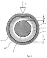
- the expanded protecting element continuously supported by the underlying metal shield, is capable to distribute the impact energy on a relatively large area around the impact position, as shown in Figure 6 .
- the deformation of the equipotential lines of the electric field is reduced (and associated with a larger area as well), so that they get less close than in the case of the helical wires described above, with an impact of the same energy.
Claims (13)
- Procédé de fabrication d'un câble électrique (1), comprenant les phases consistant à :- avancer (201) un conducteur (2) à une vitesse d'avance prédéterminée ;- extruder (210) une couche semi-conductrice interne (3) sur la surface externe dudit conducteur (2) ;- extruder (202) une couche isolante thermoplastique (4) dans une position radialement externe au conducteur (2) ;- extruder (310) une couche semi-conductrice externe (5) autour de ladite couche isolante (4) pour obtenir ainsi une âme de câble (2a) comprenant ledit conducteur (2), ladite couche semi-conductrice interne (3), ladite couche isolante thermoplastique (4) et ladite couche semi-conductrice externe (5) ;- refroidir (203) ladite âme de câble (2a) ;- former (210) un blindage métallique circonférentiellement fermé (6) autour de ladite âme de câble (2a) ;dans lequel le conducteur est avancé en continu, de sorte que le temps qui s'écoule entre la fin de la phase de refroidissement (203) et le début de la phase de formation du blindage (210) est inversement proportionnel à la vitesse d'avance du conducteur (2), dans lequel ledit procédé comprend en outre la phase consistant à appliquer un élément de protection contre les impacts (20) autour dudit blindage métallique circonférentiellement fermé (6), ladite phase d'application dudit élément de protection contre les impacts (20) comprenant .- l'application d'une couche polymère non expansée (21) autour dudit blindage métallique (6), et- l'application d'une couche polymère expansée (22) autour de la couche polymère non expansée (21).
- Procédé selon la revendication 1, dans lequel la phase de formation (210) comprend l'étape consistant à plier longitudinalement une feuille métallique (60) autour de ladite couche isolante extrudée (4).
- Procédé selon la revendication 2, dans lequel la phase de formation (210) comprend l'étape consistant à faire chevaucher les bords de ladite feuille métallique (60) pour former le blindage métallique (6).
- Procédé selon la revendication 2, dans lequel la phase de formation (210) comprend l'étape consistant à coller les bords de ladite feuille métallique (60) pour former le blindage métallique (6).
- Procédé selon la revendication 1, comprenant en outre la phase consistant à fournir le conducteur (2) sous la forme d'une tige métallique.
- Procédé selon la revendication 1, comprenant en outre la phase consistant à appliquer une couche d'apprêt autour du blindage métallique (6).
- Procédé selon la revendication 6, dans lequel la phase d'application de la couche d'apprêt est réalisée par extrusion.
- Procédé selon la revendication 1, comprenant en outre la phase consistant à appliquer une gaine externe (23) autour du blindage métallique (6).
- Procédé selon la revendication 8, dans lequel la gaine externe (23) est appliquée autour de la couche polymère expansée (22).
- Procédé selon la revendication 1, dans lequel la phase de refroidissement (203) de la couche isolante extrudée (4) est réalisée en avançant longitudinalement le conducteur (2) pourvu de la couche isolante thermoplastique (4) à travers un dispositif de refroidissement allongé.
- Procédé selon la revendication 1, dans lequel le matériau polymère thermoplastique de la couche isolante (4) est choisi parmi : des polyoléfines, des copolymères de différentes oléfines, des copolymères d'une oléfine avec un ester à insaturation éthylénique, des polyesters, des polyacétates, des polymères cellulosiques, des polycarbonates, des polysulfones, des résines phénoliques, des résines uréiques, des polycétones, des polyacrylates, des polyamides, des polyamines, et leurs mélanges.
- Procédé selon la revendication 11, dans lequel ledit matériau polymère thermoplastique est choisi parmi : le polyéthylène (PE), le polypropylène (PP), l'éthylène-acétate de vinyle (EVA), l'éthylène-acrylate de méthyle (EMA), l'éthylène-acrylate d'éthyle (EEA), l'éthylène-acrylate de butyle (EBA), des copolymères thermoplastiques d'éthylène/a-oléfine, le polystyrène, des résines d'acrylonitrile/butadiène/styrène (ABS), du chlorure de polyvinyle (PVC), du polyuréthane, des polyamides, du polyéthylène téréphtalate (PET), du polybutylène téréphtalate (PBT), et leurs copolymères ou leurs mélanges par voie mécanique.
- Procédé selon la revendication 1, dans lequel le matériau polymère thermoplastique de la couche isolante (4) comprend une quantité prédéterminée d'un liquide diélectrique.
Applications Claiming Priority (1)
| Application Number | Priority Date | Filing Date | Title |
|---|---|---|---|
| PCT/EP2003/008194 WO2005015577A1 (fr) | 2003-07-25 | 2003-07-25 | Procede continu de fabrication de cables electriques |
Publications (2)
| Publication Number | Publication Date |
|---|---|
| EP1649471A1 EP1649471A1 (fr) | 2006-04-26 |
| EP1649471B1 true EP1649471B1 (fr) | 2016-09-07 |
Family
ID=34129886
Family Applications (2)
| Application Number | Title | Priority Date | Filing Date |
|---|---|---|---|
| EP03817932.1A Expired - Lifetime EP1649471B1 (fr) | 2003-07-25 | 2003-07-25 | Procede continu de fabrication de cables electriques |
| EP03785924.6A Expired - Lifetime EP1652196B1 (fr) | 2003-07-25 | 2003-12-18 | Procede continu servant a fabriquer des cables electriques |
Family Applications After (1)
| Application Number | Title | Priority Date | Filing Date |
|---|---|---|---|
| EP03785924.6A Expired - Lifetime EP1652196B1 (fr) | 2003-07-25 | 2003-12-18 | Procede continu servant a fabriquer des cables electriques |
Country Status (15)
| Country | Link |
|---|---|
| US (2) | US7459635B2 (fr) |
| EP (2) | EP1649471B1 (fr) |
| JP (2) | JP2007515742A (fr) |
| KR (1) | KR20060056953A (fr) |
| CN (2) | CN100514509C (fr) |
| AR (2) | AR045086A1 (fr) |
| AU (2) | AU2003250174B2 (fr) |
| BR (2) | BRPI0318419B1 (fr) |
| CA (2) | CA2534261C (fr) |
| ES (2) | ES2605010T3 (fr) |
| HK (1) | HK1101521A1 (fr) |
| MY (2) | MY138405A (fr) |
| NZ (1) | NZ545519A (fr) |
| RU (1) | RU2317608C2 (fr) |
| WO (2) | WO2005015577A1 (fr) |
Families Citing this family (45)
| Publication number | Priority date | Publication date | Assignee | Title |
|---|---|---|---|---|
| EP2083043B1 (fr) | 2002-08-12 | 2017-01-18 | ExxonMobil Chemical Patents Inc. | Compositions de polyoléfine plastifiées |
| US7271209B2 (en) | 2002-08-12 | 2007-09-18 | Exxonmobil Chemical Patents Inc. | Fibers and nonwovens from plasticized polyolefin compositions |
| US8003725B2 (en) | 2002-08-12 | 2011-08-23 | Exxonmobil Chemical Patents Inc. | Plasticized hetero-phase polyolefin blends |
| US7998579B2 (en) | 2002-08-12 | 2011-08-16 | Exxonmobil Chemical Patents Inc. | Polypropylene based fibers and nonwovens |
| US7531594B2 (en) | 2002-08-12 | 2009-05-12 | Exxonmobil Chemical Patents Inc. | Articles from plasticized polyolefin compositions |
| US8192813B2 (en) * | 2003-08-12 | 2012-06-05 | Exxonmobil Chemical Patents, Inc. | Crosslinked polyethylene articles and processes to produce same |
| US8389615B2 (en) | 2004-12-17 | 2013-03-05 | Exxonmobil Chemical Patents Inc. | Elastomeric compositions comprising vinylaromatic block copolymer, polypropylene, plastomer, and low molecular weight polyolefin |
| CN101218296B (zh) | 2005-07-15 | 2010-12-08 | 埃克森美孚化学专利公司 | 弹性体组合物 |
| JP4868218B2 (ja) * | 2005-08-23 | 2012-02-01 | 株式会社シーティーイー | 電線被覆機 |
| US8378216B2 (en) * | 2006-11-15 | 2013-02-19 | Prysmian S.P.A. | Energy cable |
| GB0711410D0 (en) * | 2007-06-13 | 2007-07-25 | Bwe Ltd | Apparatus and method for the production of cable having a core sheathed with an aluminium based sheath |
| PL2015314T3 (pl) * | 2007-07-12 | 2012-09-28 | Borealis Tech Oy | Proces wytwarzania i sieciowania kabla zwierającego polimerową kompozycję, oraz usieciowany kabel |
| EP2015315B1 (fr) * | 2007-07-12 | 2012-12-12 | Borealis Technology Oy | Processus de préparation et réticulation d'un câble comportant une composition de polymère et câble réticulé |
| GB2456316B (en) * | 2008-01-10 | 2012-02-15 | Technip France | Umbilical |
| KR101416332B1 (ko) * | 2008-07-10 | 2014-07-08 | 보레알리스 아게 | 케이블 제조방법 |
| US7985922B2 (en) * | 2008-12-18 | 2011-07-26 | Thomas C. Maganas | Apparatus and methods for boosting electrical power |
| US8162260B2 (en) * | 2008-12-18 | 2012-04-24 | Maganas Thomas C | Monomolecular carbon-based film for forming lubricious surface on aircraft parts |
| US7959972B2 (en) * | 2008-12-18 | 2011-06-14 | Maganas Thomas C | Monomolecular carbon-based film for forming lubricious surface on aircraft parts |
| US7759579B2 (en) * | 2008-12-18 | 2010-07-20 | Maganas Thomas C | Monomolecular carbon-based film for enhancing electrical power transmission |
| EP2199329A1 (fr) * | 2008-12-19 | 2010-06-23 | Borealis AG | Composition de polymère |
| CN101552054B (zh) * | 2009-05-13 | 2013-11-06 | 上海拜明电子设备有限公司 | 摆拨式防导线刮伤的叠加导线绕制设备 |
| US20100288528A1 (en) * | 2009-05-14 | 2010-11-18 | Commscope, Inc. Of North Carolina | Coaxial cables having low bond precoat layers and methods of making same |
| CA2771074C (fr) * | 2009-08-10 | 2016-08-16 | Union Carbide Chemicals & Plastics Technology Llc | Compositions elastomeres thermoplastiques comprenant des retardateurs de flamme intumescents et des synergistes de retardateurs de flamme non a base de phosphore |
| JP2011228111A (ja) * | 2010-04-20 | 2011-11-10 | Viscas Corp | 電力ケーブル |
| CN103098145A (zh) * | 2010-05-27 | 2013-05-08 | 普睿司曼电力电缆及系统美国有限责任公司 | 具有可区别于护套的半导外层的电缆 |
| KR101802554B1 (ko) | 2010-09-30 | 2017-11-28 | 다우 글로벌 테크놀로지스 엘엘씨 | 파괴 강도가 개선된 재활용가능한 열가소성 절연재 |
| CN102254624B (zh) * | 2011-04-14 | 2015-09-09 | 轻工业西安机械设计研究所 | 一种电缆的生产设备 |
| CN102426885A (zh) * | 2011-04-26 | 2012-04-25 | 上海市电力公司 | 一种柔性直流输电电缆脱气的方法 |
| BR112014000359A2 (pt) * | 2011-07-08 | 2019-11-19 | General Cable Tech Corp | componente de cabo blindado e método para aplicar blindagem a substrato |
| KR102133809B1 (ko) * | 2012-09-27 | 2020-07-15 | 다우 글로벌 테크놀로지스 엘엘씨 | 가교성 에틸렌-기재 중합체 조성물 내의 퍼옥시드 이동을 감소시키는 방법 |
| KR102231397B1 (ko) | 2013-03-12 | 2021-03-25 | 다우 글로벌 테크놀로지스 엘엘씨 | 두꺼운 절연 층을 갖는 전력 케이블 및 그의 제조 방법 |
| CH708133B1 (de) | 2013-06-03 | 2017-06-30 | Leoni Studer Ag | Elektrokabel, insbesondere für Solar- bzw. Windkraftwerke. |
| EA025064B1 (ru) * | 2013-06-26 | 2016-11-30 | Открытое Акционерное Общество "Нпо "Стример" | Устройство для грозозащиты и линия электропередачи, снабженная таким устройством |
| EP3103123A4 (fr) * | 2014-02-07 | 2017-09-20 | General Cable Technologies Corporation | Procédés de formation de câbles dotés de revêtements améliorés |
| CN104057563B (zh) * | 2014-06-17 | 2016-06-15 | 丹阳市伟鹤祥线缆制造有限公司 | 一种用于无卤交联线冷却的环侧吹风装置 |
| EP3234013B1 (fr) * | 2014-12-17 | 2018-11-28 | Prysmian S.p.A. | Câble d'alimentation possédant une couche semi-conductrice pouvant être dénudée à froid |
| AU2016202308B2 (en) * | 2015-04-24 | 2020-12-10 | Lightning Protection International Pty Ltd | Down conductor |
| JP6571471B2 (ja) * | 2015-09-28 | 2019-09-04 | 株式会社イノアックコーポレーション | 樹脂組成物、発泡体、微生物担体および発泡体の製造方法 |
| FR3045920B1 (fr) * | 2015-12-18 | 2018-01-19 | Nexans | Cable electrique a moyenne ou haute tension |
| WO2018122572A1 (fr) * | 2016-12-27 | 2018-07-05 | Prysmian S.P.A. | Câble électrique ayant une couche protectrice |
| JP7124723B2 (ja) * | 2019-01-16 | 2022-08-24 | 株式会社オートネットワーク技術研究所 | 融着層付き絶縁電線 |
| RU200427U1 (ru) * | 2020-07-29 | 2020-10-23 | Акционерное общество "Научно-исследовательский, проектно-конструкторский и технологический кабельный институт (НИКИ) г. Томск с опытным производством" (АО "НИКИ г. Томск") | Электрический кабель для установок погружных электронасосов |
| AU2022228465A1 (en) * | 2021-03-05 | 2023-10-12 | Felix Sorkin | U-shaped extrusion line |
| FR3128572A1 (fr) * | 2021-10-22 | 2023-04-28 | Nexans | Procédé de fabrication d’un câble électrique par refroidissement contrôlé |
| CN114255935B (zh) * | 2021-12-29 | 2023-11-03 | 河北万方线缆集团有限公司 | 一种用于电缆加工的塑胶挤出机 |
Citations (9)
| Publication number | Priority date | Publication date | Assignee | Title |
|---|---|---|---|---|
| JPS5783616A (en) * | 1980-11-14 | 1982-05-25 | Toshiba Corp | Output controller for combined cycle |
| US4469539A (en) * | 1981-02-10 | 1984-09-04 | Anaconda-Ericsson, Inc. | Process for continuous production of a multilayer electric cable |
| EP0221449A2 (fr) * | 1985-10-31 | 1987-05-13 | PIRELLI CAVI S.p.A. | Câble électrique et matériau utilisé pour le revêtement de conducteurs électriques agissant comme isolant ou couche de revêtement |
| JPH0517845A (ja) * | 1990-10-31 | 1993-01-26 | Sumitomo Electric Ind Ltd | 過共晶アルミニウム−シリコン系合金粉末およびその製造方法 |
| JPH0850828A (ja) * | 1994-08-04 | 1996-02-20 | Yazaki Corp | 縦型冷却水槽を用いた電線被覆方法および装置 |
| JPH10106358A (ja) * | 1996-06-21 | 1998-04-24 | Pirelli Cavi & Syst Spa | 水トリー抵抗性絶縁用組成物 |
| JP2000113738A (ja) * | 1998-10-06 | 2000-04-21 | Sumitomo Electric Ind Ltd | 電力ケーブルとそのリサイクル方法 |
| WO2002047092A1 (fr) * | 2000-12-06 | 2002-06-13 | Pirelli S.P.A. | Procede de production de cable a revetement recyclable |
| WO2004003940A1 (fr) * | 2002-06-28 | 2004-01-08 | Pirelli & C. S.P.A. | Cable compact resistant aux chocs |
Family Cites Families (40)
| Publication number | Priority date | Publication date | Assignee | Title |
|---|---|---|---|---|
| DE1665739A1 (de) * | 1963-09-25 | 1971-03-18 | Siemens Ag | Verfahren zum Isolieren duenner elektrischer Leiter |
| US3590141A (en) * | 1969-02-17 | 1971-06-29 | Dow Chemical Co | Electric cable having improved resistance to moisture |
| US3849192A (en) * | 1972-05-12 | 1974-11-19 | Gen Cable Corp Inc | Method of applying and cooling low density polyethylene cable insulation |
| US4130450A (en) * | 1975-11-12 | 1978-12-19 | General Cable Corporation | Method of making extruded solid dielectric high voltage cable resistant to electrochemical trees |
| US4104210A (en) * | 1975-12-17 | 1978-08-01 | Monsanto Company | Thermoplastic compositions of high unsaturation diene rubber and polyolefin resin |
| FR2407557A1 (fr) * | 1977-10-27 | 1979-05-25 | Cables De Lyon Geoffroy Delore | Cable d'energie etanche et machine pour le fabriquer |
| DE3011868A1 (de) * | 1980-03-27 | 1981-10-01 | Kabel- und Metallwerke Gutehoffnungshütte AG, 3000 Hannover | Feuchtigkeitsgeschuetztes elektrisches energiekabel |
| JPH0126005Y2 (fr) * | 1980-11-10 | 1989-08-03 | ||
| JPS6119012A (ja) * | 1984-07-04 | 1986-01-27 | 日立電線株式会社 | 熱膨脹抑止形電力ケ−ブルの製造方法 |
| US4963695A (en) * | 1986-05-16 | 1990-10-16 | Pirelli Cable Corporation | Power cable with metallic shielding tape and water swellable powder |
| US4711811A (en) * | 1986-10-22 | 1987-12-08 | E. I. Du Pont De Nemours And Company | Thin wall cover on foamed insulation on wire |
| SE460670B (sv) | 1988-01-15 | 1989-11-06 | Abb Cables Ab | Termoplastiskt bearbetbar komposition omfattande en matris av ett termoplastiskt polymermaterial och i denna matris foerdelade fina partiklar av ett vulkaniserat gummi samt saett att framstaella kompositionen |
| ES2055151T3 (es) * | 1988-03-16 | 1994-08-16 | Ciba Geigy Ag | Colorantes reactivos, procedimiento para su obtencion y utilizacion de los mismos. |
| GB8904592D0 (en) * | 1989-02-28 | 1989-04-12 | Beta Instr Co | Manufacture of insulated cable |
| US5112919A (en) | 1989-10-30 | 1992-05-12 | Union Carbide Chemicals & Plastics Technology Corporation | Solid feeding of silane crosslinking agents into extruder |
| US5110998A (en) * | 1990-02-07 | 1992-05-05 | E. I. Du Pont De Nemours And Company | High speed insulated conductors |
| US5153381A (en) * | 1990-03-20 | 1992-10-06 | Alcan Aluminum Corporation | Metal clad cable and method of making |
| JPH0517845U (ja) | 1991-08-12 | 1993-03-05 | 日立電線株式会社 | 発泡ポリエチレン絶縁電線 |
| US5281757A (en) * | 1992-08-25 | 1994-01-25 | Pirelli Cable Corporation | Multi-layer power cable with metal sheath free to move relative to adjacent layers |
| JPH0680221U (ja) * | 1993-04-23 | 1994-11-08 | 昭和電線電纜株式会社 | ケーブルの架橋装置 |
| JPH07192543A (ja) * | 1993-12-27 | 1995-07-28 | Mitsubishi Cable Ind Ltd | 電力ケーブル |
| CN1085383C (zh) * | 1995-05-09 | 2002-05-22 | 克拉伦斯·S·弗里曼 | 水不渗透的动力传输电缆 |
| US5926949A (en) * | 1996-05-30 | 1999-07-27 | Commscope, Inc. Of North Carolina | Method of making coaxial cable |
| UA46901C2 (uk) * | 1997-05-15 | 2002-06-17 | Піреллі Каві Е Сістемі С.П.А. | Силовий передавальний кабель, спосіб надання ударостійкості кабелю (варіанти) та спінений полімерний матеріал для нього |
| EP0981821B2 (fr) * | 1997-05-15 | 2008-12-31 | Prysmian S.p.A. | Cable avec revetement resistant aux impacts |
| CN2315639Y (zh) * | 1997-10-22 | 1999-04-21 | 江苏宝胜集团有限公司 | 防水中压交联电缆 |
| HU223024B1 (hu) * | 1997-12-22 | 2004-03-01 | Pirelli Cavi E Sistemi S.P.A. | Elektromos kábel, félvezetõ, vízzáró, expandált réteggel |
| SE512745C2 (sv) * | 1998-08-06 | 2000-05-08 | Abb Ab | Elektrisk DC-kabel med isoleringssystem omfattande en strängsprutad polyetenkomposition och en metod för framställning av sådan kabel |
| ATE264540T1 (de) * | 1998-08-19 | 2004-04-15 | Pirelli Cables Y Systemas S A | Elektrische leitung und verfahren und vorrichtung zum konfektionieren derselben |
| EP1243004B1 (fr) | 1999-12-20 | 2006-11-08 | Prysmian Cavi e Sistemi Energia S.r.l. | Cable electrique resistant a la penetration de l'eau |
| US6824870B2 (en) * | 2000-09-28 | 2004-11-30 | Pirelli S.P.A. | Cable with recyclable covering |
| NZ525495A (en) * | 2000-09-28 | 2004-07-30 | Pirelli | Cable with recyclable covering comprising thermoplastic polymer material with a dielectric liquid |
| DE10051962A1 (de) * | 2000-10-20 | 2002-05-02 | Alcatel Sa | Isolierter elektrischer Leiter mit Funktionserhalt im Brandfall |
| CN2473721Y (zh) * | 2001-03-22 | 2002-01-23 | 青岛汉缆集团有限公司 | 护套包覆有塑料导电层的电力电缆 |
| FR2822833B1 (fr) | 2001-03-27 | 2005-06-24 | Nexans | Procede de fabrication d'une composition a base de polymere reticule au moyen de silane, et composition obtenue par ce procede |
| CN1293575C (zh) * | 2001-04-20 | 2007-01-03 | 河北宝丰线缆有限公司 | 35kv xlpe绝缘低烟无卤a类阻燃电力电缆 |
| FR2829141B1 (fr) | 2001-09-03 | 2006-12-15 | Nexans | Procede de fabrication d'un corps cylindrique et cable comportant un corps obtenu par ce procede |
| CN1246861C (zh) * | 2001-12-26 | 2006-03-22 | 特变电工山东鲁能泰山电缆有限公司 | 500kV超高压交联电缆及生产工艺方法 |
| CN1326159C (zh) * | 2002-04-16 | 2007-07-11 | 皮雷利&C.有限公司 | 电缆及其制造过程 |
| EP1576624B1 (fr) * | 2002-12-23 | 2007-06-06 | Prysmian Cavi e Sistemi Energia S.r.l. | Procede de production d'une couche de revetement constituee d'une matiere expansible et reticulable dans un cable |
-
2003
- 2003-07-25 WO PCT/EP2003/008194 patent/WO2005015577A1/fr active Application Filing
- 2003-07-25 ES ES03817932.1T patent/ES2605010T3/es not_active Expired - Lifetime
- 2003-07-25 US US10/565,783 patent/US7459635B2/en not_active Expired - Lifetime
- 2003-07-25 AU AU2003250174A patent/AU2003250174B2/en not_active Expired
- 2003-07-25 BR BRPI0318419A patent/BRPI0318419B1/pt active IP Right Grant
- 2003-07-25 EP EP03817932.1A patent/EP1649471B1/fr not_active Expired - Lifetime
- 2003-07-25 CA CA2534261A patent/CA2534261C/fr not_active Expired - Lifetime
- 2003-07-25 JP JP2005507501A patent/JP2007515742A/ja active Pending
- 2003-07-25 CN CNB038269406A patent/CN100514509C/zh not_active Expired - Lifetime
- 2003-12-18 WO PCT/EP2003/014782 patent/WO2005015576A1/fr active Application Filing
- 2003-12-18 KR KR1020067001737A patent/KR20060056953A/ko not_active Application Discontinuation
- 2003-12-18 CN CNB2003801104031A patent/CN100511494C/zh not_active Expired - Fee Related
- 2003-12-18 BR BRPI0318414-5A patent/BR0318414B1/pt not_active IP Right Cessation
- 2003-12-18 ES ES03785924.6T patent/ES2636802T3/es not_active Expired - Lifetime
- 2003-12-18 AU AU2003294942A patent/AU2003294942B2/en not_active Expired
- 2003-12-18 EP EP03785924.6A patent/EP1652196B1/fr not_active Expired - Lifetime
- 2003-12-18 CA CA2542986A patent/CA2542986C/fr not_active Expired - Fee Related
- 2003-12-18 NZ NZ545519A patent/NZ545519A/en not_active IP Right Cessation
- 2003-12-18 JP JP2005507526A patent/JP2007515743A/ja active Pending
- 2003-12-18 RU RU2006105656/09A patent/RU2317608C2/ru active
- 2003-12-18 US US10/565,299 patent/US20070051450A1/en not_active Abandoned
-
2004
- 2004-07-19 MY MYPI20042885A patent/MY138405A/en unknown
- 2004-07-20 MY MYPI20042894A patent/MY139970A/en unknown
- 2004-07-23 AR ARP040102616A patent/AR045086A1/es active IP Right Grant
- 2004-07-23 AR ARP040102615A patent/AR045085A1/es active IP Right Grant
-
2007
- 2007-06-12 HK HK07106233.7A patent/HK1101521A1/xx not_active IP Right Cessation
Patent Citations (10)
| Publication number | Priority date | Publication date | Assignee | Title |
|---|---|---|---|---|
| JPS5783616A (en) * | 1980-11-14 | 1982-05-25 | Toshiba Corp | Output controller for combined cycle |
| US4469539A (en) * | 1981-02-10 | 1984-09-04 | Anaconda-Ericsson, Inc. | Process for continuous production of a multilayer electric cable |
| EP0221449A2 (fr) * | 1985-10-31 | 1987-05-13 | PIRELLI CAVI S.p.A. | Câble électrique et matériau utilisé pour le revêtement de conducteurs électriques agissant comme isolant ou couche de revêtement |
| JPH0517845A (ja) * | 1990-10-31 | 1993-01-26 | Sumitomo Electric Ind Ltd | 過共晶アルミニウム−シリコン系合金粉末およびその製造方法 |
| JPH0850828A (ja) * | 1994-08-04 | 1996-02-20 | Yazaki Corp | 縦型冷却水槽を用いた電線被覆方法および装置 |
| JPH10106358A (ja) * | 1996-06-21 | 1998-04-24 | Pirelli Cavi & Syst Spa | 水トリー抵抗性絶縁用組成物 |
| JP2000113738A (ja) * | 1998-10-06 | 2000-04-21 | Sumitomo Electric Ind Ltd | 電力ケーブルとそのリサイクル方法 |
| WO2002047092A1 (fr) * | 2000-12-06 | 2002-06-13 | Pirelli S.P.A. | Procede de production de cable a revetement recyclable |
| WO2004003940A1 (fr) * | 2002-06-28 | 2004-01-08 | Pirelli & C. S.P.A. | Cable compact resistant aux chocs |
| EP1522081A1 (fr) * | 2002-06-28 | 2005-04-13 | Pirelli & C. S.p.A. | Cable compact resistant aux chocs |
Also Published As
Similar Documents
| Publication | Publication Date | Title |
|---|---|---|
| EP1649471B1 (fr) | Procede continu de fabrication de cables electriques | |
| US6455769B1 (en) | Electrical cable having a semiconductive water-blocking expanded layer | |
| AU768890B2 (en) | Electric cable resistant to water penetration | |
| US20100000759A1 (en) | Process for manufacturing a cable resistant to external chemical agents | |
| EP1825484B1 (fr) | Procede de fabrication de cable | |
| RU2319240C2 (ru) | Способ непрерывного изготовления электрических кабелей | |
| NZ545031A (en) | Continuous process for manufacturing electrical cables | |
| KR20060115989A (ko) | 전기 케이블의 연속적인 제조 방법 | |
| PL205143B1 (pl) | Ciągły proces wytwarzania kabli elektrycznych | |
| RU2336586C1 (ru) | Способ изготовления кабеля | |
| AU2274199A (en) | Electrical cable having a semiconductive water-blocking expanded layer | |
| NZ504888A (en) | Electrical cable having a semiconductive water-blocking expanded layer |
Legal Events
| Date | Code | Title | Description |
|---|---|---|---|
| PUAI | Public reference made under article 153(3) epc to a published international application that has entered the european phase |
Free format text: ORIGINAL CODE: 0009012 |
|
| 17P | Request for examination filed |
Effective date: 20060213 |
|
| AK | Designated contracting states |
Kind code of ref document: A1 Designated state(s): AT BE BG CH CY CZ DE DK EE ES FI FR GB GR HU IE IT LI LU MC NL PT RO SE SI SK TR |
|
| REG | Reference to a national code |
Ref country code: HK Ref legal event code: DE Ref document number: 1088115 Country of ref document: HK |
|
| DAX | Request for extension of the european patent (deleted) | ||
| RAP1 | Party data changed (applicant data changed or rights of an application transferred) |
Owner name: GSCP ATHENA (LUX) II SARL |
|
| RAP1 | Party data changed (applicant data changed or rights of an application transferred) |
Owner name: PRYSMIAN (LUX) II SARL |
|
| RAP1 | Party data changed (applicant data changed or rights of an application transferred) |
Owner name: PRYSMIAN CAVI E SISTEMI ENERGIA S.R.L. |
|
| RAP1 | Party data changed (applicant data changed or rights of an application transferred) |
Owner name: PRYSMIAN S.P.A. |
|
| TPAC | Observations filed by third parties |
Free format text: ORIGINAL CODE: EPIDOSNTIPA |
|
| 17Q | First examination report despatched |
Effective date: 20130619 |
|
| TPAC | Observations filed by third parties |
Free format text: ORIGINAL CODE: EPIDOSNTIPA |
|
| TPAC | Observations filed by third parties |
Free format text: ORIGINAL CODE: EPIDOSNTIPA |
|
| GRAP | Despatch of communication of intention to grant a patent |
Free format text: ORIGINAL CODE: EPIDOSNIGR1 |
|
| RIC1 | Information provided on ipc code assigned before grant |
Ipc: H01B 13/00 20060101AFI20151012BHEP Ipc: H01B 13/26 20060101ALI20151012BHEP Ipc: H01B 7/18 20060101ALI20151012BHEP Ipc: H01B 13/14 20060101ALI20151012BHEP |
|
| INTG | Intention to grant announced |
Effective date: 20151112 |
|
| GRAS | Grant fee paid |
Free format text: ORIGINAL CODE: EPIDOSNIGR3 |
|
| GRAA | (expected) grant |
Free format text: ORIGINAL CODE: 0009210 |
|
| AK | Designated contracting states |
Kind code of ref document: B1 Designated state(s): AT BE BG CH CY CZ DE DK EE ES FI FR GB GR HU IE IT LI LU MC NL PT RO SE SI SK TR |
|
| REG | Reference to a national code |
Ref country code: GB Ref legal event code: FG4D |
|
| REG | Reference to a national code |
Ref country code: CH Ref legal event code: EP |
|
| REG | Reference to a national code |
Ref country code: IE Ref legal event code: FG4D |
|
| REG | Reference to a national code |
Ref country code: AT Ref legal event code: REF Ref document number: 827504 Country of ref document: AT Kind code of ref document: T Effective date: 20161015 |
|
| REG | Reference to a national code |
Ref country code: DE Ref legal event code: R096 Ref document number: 60349379 Country of ref document: DE |
|
| REG | Reference to a national code |
Ref country code: NL Ref legal event code: FP |
|
| REG | Reference to a national code |
Ref country code: AT Ref legal event code: MK05 Ref document number: 827504 Country of ref document: AT Kind code of ref document: T Effective date: 20160907 |
|
| PG25 | Lapsed in a contracting state [announced via postgrant information from national office to epo] |
Ref country code: SE Free format text: LAPSE BECAUSE OF FAILURE TO SUBMIT A TRANSLATION OF THE DESCRIPTION OR TO PAY THE FEE WITHIN THE PRESCRIBED TIME-LIMIT Effective date: 20160907 Ref country code: GR Free format text: LAPSE BECAUSE OF FAILURE TO SUBMIT A TRANSLATION OF THE DESCRIPTION OR TO PAY THE FEE WITHIN THE PRESCRIBED TIME-LIMIT Effective date: 20161208 |
|
| REG | Reference to a national code |
Ref country code: ES Ref legal event code: FG2A Ref document number: 2605010 Country of ref document: ES Kind code of ref document: T3 Effective date: 20170310 |
|
| PG25 | Lapsed in a contracting state [announced via postgrant information from national office to epo] |
Ref country code: EE Free format text: LAPSE BECAUSE OF FAILURE TO SUBMIT A TRANSLATION OF THE DESCRIPTION OR TO PAY THE FEE WITHIN THE PRESCRIBED TIME-LIMIT Effective date: 20160907 Ref country code: RO Free format text: LAPSE BECAUSE OF FAILURE TO SUBMIT A TRANSLATION OF THE DESCRIPTION OR TO PAY THE FEE WITHIN THE PRESCRIBED TIME-LIMIT Effective date: 20160907 |
|
| PG25 | Lapsed in a contracting state [announced via postgrant information from national office to epo] |
Ref country code: BE Free format text: LAPSE BECAUSE OF FAILURE TO SUBMIT A TRANSLATION OF THE DESCRIPTION OR TO PAY THE FEE WITHIN THE PRESCRIBED TIME-LIMIT Effective date: 20160907 Ref country code: BG Free format text: LAPSE BECAUSE OF FAILURE TO SUBMIT A TRANSLATION OF THE DESCRIPTION OR TO PAY THE FEE WITHIN THE PRESCRIBED TIME-LIMIT Effective date: 20161207 Ref country code: SK Free format text: LAPSE BECAUSE OF FAILURE TO SUBMIT A TRANSLATION OF THE DESCRIPTION OR TO PAY THE FEE WITHIN THE PRESCRIBED TIME-LIMIT Effective date: 20160907 Ref country code: CZ Free format text: LAPSE BECAUSE OF FAILURE TO SUBMIT A TRANSLATION OF THE DESCRIPTION OR TO PAY THE FEE WITHIN THE PRESCRIBED TIME-LIMIT Effective date: 20160907 Ref country code: PT Free format text: LAPSE BECAUSE OF FAILURE TO SUBMIT A TRANSLATION OF THE DESCRIPTION OR TO PAY THE FEE WITHIN THE PRESCRIBED TIME-LIMIT Effective date: 20170109 Ref country code: AT Free format text: LAPSE BECAUSE OF FAILURE TO SUBMIT A TRANSLATION OF THE DESCRIPTION OR TO PAY THE FEE WITHIN THE PRESCRIBED TIME-LIMIT Effective date: 20160907 |
|
| REG | Reference to a national code |
Ref country code: DE Ref legal event code: R097 Ref document number: 60349379 Country of ref document: DE |
|
| PLBE | No opposition filed within time limit |
Free format text: ORIGINAL CODE: 0009261 |
|
| STAA | Information on the status of an ep patent application or granted ep patent |
Free format text: STATUS: NO OPPOSITION FILED WITHIN TIME LIMIT |
|
| REG | Reference to a national code |
Ref country code: FR Ref legal event code: PLFP Year of fee payment: 15 |
|
| PG25 | Lapsed in a contracting state [announced via postgrant information from national office to epo] |
Ref country code: DK Free format text: LAPSE BECAUSE OF FAILURE TO SUBMIT A TRANSLATION OF THE DESCRIPTION OR TO PAY THE FEE WITHIN THE PRESCRIBED TIME-LIMIT Effective date: 20160907 |
|
| 26N | No opposition filed |
Effective date: 20170608 |
|
| PG25 | Lapsed in a contracting state [announced via postgrant information from national office to epo] |
Ref country code: SI Free format text: LAPSE BECAUSE OF FAILURE TO SUBMIT A TRANSLATION OF THE DESCRIPTION OR TO PAY THE FEE WITHIN THE PRESCRIBED TIME-LIMIT Effective date: 20160907 |
|
| REG | Reference to a national code |
Ref country code: HK Ref legal event code: GR Ref document number: 1088115 Country of ref document: HK |
|
| REG | Reference to a national code |
Ref country code: CH Ref legal event code: PL |
|
| REG | Reference to a national code |
Ref country code: IE Ref legal event code: MM4A |
|
| PG25 | Lapsed in a contracting state [announced via postgrant information from national office to epo] |
Ref country code: IE Free format text: LAPSE BECAUSE OF NON-PAYMENT OF DUE FEES Effective date: 20170725 Ref country code: CH Free format text: LAPSE BECAUSE OF NON-PAYMENT OF DUE FEES Effective date: 20170731 Ref country code: LI Free format text: LAPSE BECAUSE OF NON-PAYMENT OF DUE FEES Effective date: 20170731 |
|
| PG25 | Lapsed in a contracting state [announced via postgrant information from national office to epo] |
Ref country code: LU Free format text: LAPSE BECAUSE OF NON-PAYMENT OF DUE FEES Effective date: 20170725 |
|
| REG | Reference to a national code |
Ref country code: FR Ref legal event code: PLFP Year of fee payment: 16 |
|
| PG25 | Lapsed in a contracting state [announced via postgrant information from national office to epo] |
Ref country code: MC Free format text: LAPSE BECAUSE OF FAILURE TO SUBMIT A TRANSLATION OF THE DESCRIPTION OR TO PAY THE FEE WITHIN THE PRESCRIBED TIME-LIMIT Effective date: 20160907 Ref country code: HU Free format text: LAPSE BECAUSE OF FAILURE TO SUBMIT A TRANSLATION OF THE DESCRIPTION OR TO PAY THE FEE WITHIN THE PRESCRIBED TIME-LIMIT; INVALID AB INITIO Effective date: 20030725 |
|
| PGFP | Annual fee paid to national office [announced via postgrant information from national office to epo] |
Ref country code: NL Payment date: 20190726 Year of fee payment: 17 |
|
| PG25 | Lapsed in a contracting state [announced via postgrant information from national office to epo] |
Ref country code: CY Free format text: LAPSE BECAUSE OF NON-PAYMENT OF DUE FEES Effective date: 20160907 |
|
| PGFP | Annual fee paid to national office [announced via postgrant information from national office to epo] |
Ref country code: ES Payment date: 20190801 Year of fee payment: 17 Ref country code: FI Payment date: 20190729 Year of fee payment: 17 Ref country code: DE Payment date: 20190729 Year of fee payment: 17 |
|
| PGFP | Annual fee paid to national office [announced via postgrant information from national office to epo] |
Ref country code: GB Payment date: 20190729 Year of fee payment: 17 |
|
| PG25 | Lapsed in a contracting state [announced via postgrant information from national office to epo] |
Ref country code: TR Free format text: LAPSE BECAUSE OF FAILURE TO SUBMIT A TRANSLATION OF THE DESCRIPTION OR TO PAY THE FEE WITHIN THE PRESCRIBED TIME-LIMIT Effective date: 20160907 |
|
| REG | Reference to a national code |
Ref country code: DE Ref legal event code: R119 Ref document number: 60349379 Country of ref document: DE |
|
| REG | Reference to a national code |
Ref country code: FI Ref legal event code: MAE |
|
| REG | Reference to a national code |
Ref country code: NL Ref legal event code: MM Effective date: 20200801 |
|
| GBPC | Gb: european patent ceased through non-payment of renewal fee |
Effective date: 20200725 |
|
| PG25 | Lapsed in a contracting state [announced via postgrant information from national office to epo] |
Ref country code: GB Free format text: LAPSE BECAUSE OF NON-PAYMENT OF DUE FEES Effective date: 20200725 Ref country code: FI Free format text: LAPSE BECAUSE OF NON-PAYMENT OF DUE FEES Effective date: 20200725 Ref country code: NL Free format text: LAPSE BECAUSE OF NON-PAYMENT OF DUE FEES Effective date: 20200801 |
|
| PG25 | Lapsed in a contracting state [announced via postgrant information from national office to epo] |
Ref country code: DE Free format text: LAPSE BECAUSE OF NON-PAYMENT OF DUE FEES Effective date: 20210202 |
|
| REG | Reference to a national code |
Ref country code: ES Ref legal event code: FD2A Effective date: 20211228 |
|
| PG25 | Lapsed in a contracting state [announced via postgrant information from national office to epo] |
Ref country code: ES Free format text: LAPSE BECAUSE OF NON-PAYMENT OF DUE FEES Effective date: 20200726 |
|
| PGFP | Annual fee paid to national office [announced via postgrant information from national office to epo] |
Ref country code: IT Payment date: 20220721 Year of fee payment: 20 |
|
| PGFP | Annual fee paid to national office [announced via postgrant information from national office to epo] |
Ref country code: FR Payment date: 20220725 Year of fee payment: 20 |