EP1647513A2 - Ascenseur multi-cabines - Google Patents
Ascenseur multi-cabines Download PDFInfo
- Publication number
- EP1647513A2 EP1647513A2 EP05007196A EP05007196A EP1647513A2 EP 1647513 A2 EP1647513 A2 EP 1647513A2 EP 05007196 A EP05007196 A EP 05007196A EP 05007196 A EP05007196 A EP 05007196A EP 1647513 A2 EP1647513 A2 EP 1647513A2
- Authority
- EP
- European Patent Office
- Prior art keywords
- drive
- rope
- pulleys
- belt
- cages
- Prior art date
- Legal status (The legal status is an assumption and is not a legal conclusion. Google has not performed a legal analysis and makes no representation as to the accuracy of the status listed.)
- Withdrawn
Links
Images


Classifications
-
- B—PERFORMING OPERATIONS; TRANSPORTING
- B66—HOISTING; LIFTING; HAULING
- B66B—ELEVATORS; ESCALATORS OR MOVING WALKWAYS
- B66B9/00—Kinds or types of lifts in, or associated with, buildings or other structures
-
- B—PERFORMING OPERATIONS; TRANSPORTING
- B66—HOISTING; LIFTING; HAULING
- B66B—ELEVATORS; ESCALATORS OR MOVING WALKWAYS
- B66B11/00—Main component parts of lifts in, or associated with, buildings or other structures
- B66B11/0065—Roping
- B66B11/008—Roping with hoisting rope or cable operated by frictional engagement with a winding drum or sheave
- B66B11/0095—Roping with hoisting rope or cable operated by frictional engagement with a winding drum or sheave where multiple cars drive in the same hoist way
-
- B—PERFORMING OPERATIONS; TRANSPORTING
- B66—HOISTING; LIFTING; HAULING
- B66B—ELEVATORS; ESCALATORS OR MOVING WALKWAYS
- B66B9/00—Kinds or types of lifts in, or associated with, buildings or other structures
- B66B9/003—Kinds or types of lifts in, or associated with, buildings or other structures for lateral transfer of car or frame, e.g. between vertical hoistways or to/from a parking position
Definitions
- the present invention relates to a multicar elevator, and more particular, to a multicar elevator, in which a plurality of cages provided in a shaft moves in circulation.
- JP-A-8-26629 describes an example of conventional multicar elevators.
- the multicar elevator described in this document two main ropes arranged in parallel to each other are wound around a drive wheel and a deflector wheel.
- the main ropes form loops each comprising an ascent portion, a descent portion, and upper and lower horizontal portions.
- a connection beam straddles the two main ropes.
- Passenger cages are rotatably mounted on the connection beam.
- the main ropes and the passenger cages form circulating loops. Plural sets of such circulating loops are provided, and drive sources for independently driving the drive wheels are provided on the respective circulating loops.
- the invention has been thought of in view of the disadvantage of the prior art described above, and has it object to provide for stable operation and improve reliability in a multicar elevator.
- Another object of the invention is to reduce vibration and noise in a multicar elevator.
- a circulation type multicar elevator comprising plural pairs of passenger cages each connected to both ends of two ropes diagonally arranged, and wherein the ropes connecting the pair of passenger cages are driven by a first plurality of rope drive pulleys arranged on a smooth curve or a line, which includes smooth curves and straight lines.
- the plurality of rope drive pulleys are provided separately every pair of cages and arranged in different positions from one another in a direction of passenger cage travel.
- the circulation type multicar elevator further comprises rope drive means for driving the two ropes
- the rope drive means comprises a drive motor, a belt drive shaft that transmits motive power of the drive motor to a rope drive system for the ropes diagonally arranged, and a first drive belt stretched round the belt drive shaft and the drive motor
- the rope drive system comprises second drive pulleys fixedly mounted coaxially to the first plurality of rope drive pulleys to synchronously rotate therewith, tension pulleys positioned between the second drive pulleys, and a second drive belt stretched round the second drive pulleys and the tension pulleys.
- a multicar elevator comprising plurality of cages arranged in an ascent and descent path, ropes pairing and connect the plurality of cages, and drive means for driving the ropes
- the drive means comprises a plurality of rope drive pulleys, on which the ropes are stretched, and which are arranged above and below the ascent and descent path and driven to cause the cages to travel, the plurality of rope drive pulleys being dispersedly arranged on an arc or a smooth curve, and wherein the plurality of rope drive pulleys are grouped, a drive motor is provided every group to rotatingly drive the plurality of rope drive pulleys, and the respective groups correspond to the pairs of cages.
- the multicar elevator further comprises fourth drive pulleys mounted on one end sides of those shafts, on the other end sides of which the rope drive pulleys are mounted, the shafts having substantially the same length every group, and second drive belts stretched every group round the fourth drive pulleys, and wherein the motors drive the second drive belts through first drive belts to rotate the plurality of rope drive pulleys of the same group at the same rotating speed.
- the multicar elevator further comprises rope fastening portions arranged in diagonal positions on a top of the cage, and wherein the rope drive pulleys and the fourth drive pulleys are arranged above the ascent and descent path to be positioned corresponding to diagonal positions on the cage in a position, in which the cage advances straight, and the pair of cages are connected at the rope fastening portions to the ropes to form two rope loop systems.
- the drive means comprises two rope drive systems corresponding to the two rope loop systems, a belt drive shaft having a differential gear mechanism between the rope drive systems, a second drive pulley mounted on an intermediate portion of the belt drive shaft, and third drive pulleys mounted on both ends of the belt drive shaft, and wherein a first drive pulley mounted to the motor and the second drive pulley are connected to each other through the first drive belt, and the third drive pulleys, respectively, mounted on both shaft ends are connected to the fourth drive pulleys through the second drive belt, and wherein the second drive belt, the third drive pulleys, and the fourth drive pulleys constitute the rope drive systems, and the drive means synchronously drive the two rope drive systems.
- the rope fastening portions are formed to be turnable, and counterweights and rotation damping devices are provided on turning shafts of the rope fastening portions.
- springs are mounted on the rope fastening portions to adjust rope tension and absorb extension and contraction of rope length.
- the multicar elevator further comprises further drive means, provided on the rope fastening portions, for making the cage independently movable vertically.
- the drive motor is provided in a position above the rope drive pulleys and the fourth drive pulleys, or axially away from the belt drive shaft.
- the multicar elevator further comprises a first tension roller arranged between the fourth drive pulleys to give tension the second belt, a second tension roller arranged above the first tension roller to have the second belt stretched thereround, a breakage sensor provided on the second tension roller or the third drive pulley to detect breakage of the second belt, and a brake device provided in the vicinity of the fourth drive pulleys to give a brake force to the fourth drive pulleys and having an electromagnetic solenoid.
- the multicar elevator further comprises a detection device provided in the vicinity of the second belt to detect breakage of the second belt, and a brake device mounted on an output shaft of the differential gear mechanism, and wherein the brake device is actuated when the detection device detects breakage of the second belt.
- FIG. 1 is a front view showing a whole construction of the multicar elevator.
- a circulating path comprises ascent and descent paths 1A, 1B in right and left rows and reversal movement sections 2A, 2B positioned above and below the ascent and descent paths 1A, 1B.
- Six cages 3A-3B move in a clockwise direction through the circulating path.
- Cages 3A, 3B are arranged symmetrically in positions corresponding to substantially halves of a length of the circulating path and ropes 4A, 4B connect between the cages 3A, 3B.
- a pair of cages 3A, 3B and a pair of ropes 4A, 4B form one group.
- a pair of cages 3C, 3D, and a pair of cages 3E, 3F are also connected together by other ropes (not shown) to form other groups.
- six cages 3A-3F constitute three groups.
- Rope fasteners 5 are mounted on a left-rear and a right-front of an upper surface of each of the cages 3A-3F.
- Two routes that is, the rope 4B clamped at a left-rear of each of the cages 3A-3F, and the rope 4A clamped at right-front of each of the cages 3A-3F are used.
- the rope 4A and the rope 4B of the respective routes are wound round a plurality of first pulleys (illustration thereof being omitted in Fig. 1) arranged in upper and lower rope fastener guide rails 13A-13D, details of which are described later, to form a loop.
- a loop formed by the cages 3C, 3D and a loop formed by the cages 3E, 3F are also constructed in the same manner as that of the cages 3A, 3B.
- a drive motor 23a is provided on an upper portion of the upper reversal movement section 2A and fixed to an associated building.
- a pinion is mounted on a shaft end of the drive motor 23a to mesh with a differential gear 6a.
- Different output shafts are connected to the differential gear 6a in a front-rear direction, the front output shaft acts to drive the rope 4A on the right-front side, and the rear output shaft acts to drive the rope 4B on the left-rear side. Therefore, belt drive pulleys, respectively, are mounted on the front and rear output shafts of the differential gear 6a.
- Drive belts 24 are stretched round the belt drive pulleys.
- the drive belts 24 are also stretched round second pulleys, which are mounted coaxial with the above-described plurality of first pulleys arranged in the upper rope fastener guide rails 13A, 13B. Accordingly, when the second pulleys rotate, the first pulleys also rotate to circulatingly move the cages 3 with frictional forces of the rope 4A and the rope 4B stretched round the first pulleys.
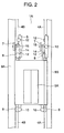
- Fig. 2 shows, in front view, a state, in which the cage 3A upwardly moving is arranged in the ascent and descent path 1A.
- the same construction and operation as those described above are also applied to the other cages 3B-3F and the ascent and descent path 1B.
- Vertically extending guide rails 9A, 9B formed in straight are arranged on both right and left sides of the ascent and descent path 1A.
- the guide rail 9B also serves as a guide rail for the adjacent ascent and descent path 1B.
- Guide rollers 8 are mounted on both right and left end sides of an upper surface of the cage 3A and on both right and left end sides of a lower surface of the cage 3A to be able to roll along the guide rails 9A, 9B. Accordingly, the cage 3A can ascend along the guide rails 9A, 9B in the ascent and descent path 1A with the use of the guide rollers 8 mounted top and bottom and right and left thereon.
- the rope fasteners 5 are provided on the upper surface of the cage 3A to mount the ropes 4A, 4B, which suspend and drive the cage 3A, to the cage 3A.
- Rope fastener supports 14 are mounted on and extended upward from the cage 3A, and horizontally extending rotating shafts 15 are provided on the rope fastener supports 14.
- the rotating shafts 15 rotatably engage with the rope fasteners 5.
- the rope fasteners 5 tend to incline due to dead weight thereof even when the rotating shafts 15 are arranged on axes of the ropes 4A, 4B.
- the rope fasteners 5 are adjusted in frame shape or the like to make centers of gravity of the rope fasteners 5 in agreement with axes of the ropes 4A, 4B.
- rope fastener counterweights 7 are mounted on the rotating shafts 15 of the rope fasteners 5. Further, in order to suppress oscillation generated by swinging movements of the rope fasteners 5, rotation damping devices (not shown) are mounted to the rotating shafts 15.
- rotation damping devices (not shown) are mounted to the rotating shafts 15.
- the counterweights 7 are used according to the embodiment to prevent the rope fasteners 5 from inclining, vertically extending, straight guide rails may be provided on the ascent and descent paths 1A, 1B to support the rope fasteners 5 and rope fastener guide rollers 12 may be provided on the rope fasteners 5 to be pushed against the guide rails.
- brakes for restraining rotation of the rotating shafts 15 may be mounted in place of the rope fastener counterweights 7 and the rotation damping devices.
- Fig. 3 shows details of the upper reversal movement section 2A, in which the cage 3A makes reversal movement from the left ascent and descent path 1A to the right ascent and descent path 1B.
- the lower reversal movement section 2B is constructed in the same manner as that of the upper reversal movement section 2A and the cage 3A is the same in operation in the lower reversal movement section 2B as that of the upper reversal movement section 2A.
- the guide rails 9A out of the guide rails 9A, 9B provided in the ascent and descent paths 1A, 1B are provided to extend to positions slightly projecting into the reversal movement section 2A from the ascent and descent path 1A.
- the guide rail 9B is mounted to extend only to a position inward about a height of the cage 3A in the ascent and descent paths 1A, 1B. This enables the cage 3A to cross the ascent and descent paths 1A, 1B in the reversal movement section 2A.
- reversal guide rails 11A, 11B are provided in the ascent and descent paths 1A, 1B.
- the reversal guide rails 11A, 11B are arcuate in shape and arranged forwardly of a front surface of and rearwardly of a rear surface of the cage 3A so as not to interfere with the cage 3A when the cage 3A moves laterally.
- the reversal guide rails 11A, 11B are discontinuous above the guide rail 9B. This eliminates interference between the rope fasteners 5 and the reversal guide rails 11A, 11B.
- Notches 11x, 11y are formed in regions, in which travel loci of the rope fasteners 5 and the reversal guide rails 11A, 11B intersect each other.
- the reversal guide rails 11A, 11B are arranged so that the reversal guide rollers 10 on one side come into contact with the reversal guide rails 11B to be able to support the cage 3A before the reversal guide rollers 10 on the other side pass the reversal guide rails 11A to reach the notches 11x.
- no notches are formed in the lower reversal movement section 2B, in which the rope fasteners 5 and reversal guide rails 11 do not interfere with each other, thus enabling the reversal guide rollers 10 to smoothly advance.
- the rope fasteners 5 provided on the upper surface of the cage 3A are capable of swinging about the rotating shafts 15.
- the rope fastener 5 are mounted on rope fastener guide rollers 12.
- the rope fastener guide rails 13A, 13B are provided in the reversal movement section 2A to guide the rope fastener guide rollers 12. Ends of the rope fastener guide rails 13A, 13B are extended slightly into the ascent and descent paths 1A, 1B.
- the rope fastener guide rails 13A, 13B are similar in shape to the reversal guide rails 11A, 11B and arranged in different positions in the front-rear direction.
- the rope fastener guide rails 13A, 13B overlap each other between the ascent and descent paths 1A, 1B in a right and left direction since there is no obstruction.
- Rope fastener guide rails 13C, 13D are likewise provided in the lower reversal movement section 2B.
- the rope fastener guide rails 13C, 13D are similar in shape to the reversal guide rail 11 arranged therebelow and overlap each other between the ascent and descent paths 1A, 1B.
- the rope fastener guide rails 13C, 13D are also arranged in different positions in the front-rear direction. Thereby, the cage 3A can be caused to travel along the rope fastener guide rails 13A to 13D, which include curved portions.
- the cage 3A makes lateral movements while having the rope fastener guide rollers 12 abutting against the rope fastener guide rails 13A-13D provided above the cage 3A and having the reversal guide rollers 10 abutting against the reversal guide rails 11, 11A, 11B provided below the cage, so that it is possible to suppress swinging of the cage 3A.
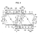
- Fig. 4 is a cross sectional view showing the multicar elevator arranged in an elevator shaft.
- a lower side in the drawing corresponds to a front door side and an upper side in the drawing corresponds to a back side.
- the rope fasteners 5 are arranged to project rearward from a rear, left corner of the cage 3A and to project forward from a front, right corner of the cage 3A.
- the ropes 4Ba, 4Aa extending from the two rope fasteners 5 suspend the cage 3A.
- the pair of ropes 4Aa, 4Ba suspending the pair of cages 3A, 3B are arranged at an outer side
- the pair of ropes 4Ab, 4Bb suspending the cages 3C, 3D are arranged at a center side
- the pair of ropes 4Ac, 4Bc suspending the cages 3E, 3F are arranged at an inner side with respect to the cages 3A to 3F.
- the reversal guide rails 11, 11A, 11B are provided out of passage regions of the cages 3A to 3F in the front-rear directions of the cages 3A to 3F so as to enable the cages 3A to 3F to pass also through the reversal movement sections 2A, 2B as described above.
- the reversal guide rollers 10 are provided on undersides of the cages 3A to 3F in four front, rear, right and left locations to correspond to the reversal guide rails 11, 11A, 11B.
- the rope fastener guide rails 13 are provided further outside in the front-rear direction of the reversal guide rails 11.
- the rope fasteners 5 will be described in detail with reference to a front view shown in Fig. 5. An explanation will be given taking the rope fastener 5, which is mounted on the right and front side of the upper surface of the cage 3A, as an example.
- the rotating shaft 15 is mounted centrally in a longitudinal direction of an elongate rope fastener frame 16 provided centrally thereof with a wide portion 16b.
- a pair of upper and lower rope fastening pulley shafts 21 extend horizontally in the vicinity of longitudinal ends of the wide portion 16b, and rope fastening pulleys 17 are mounted on the respective rope fastening pulley shafts 21.
- An upper rope part 4Aau is wound round the rope fastening pulley 17 and connected to one end of a spring rod 18 at a terminal 18b.
- the spring rod 18 is formed at the other end thereof with threads, with which a nut 20 engages.
- a spring 19 is mounted on the spring rod 18 and one end of the spring 19 is retained by the nut 20.
- the other end of the spring 19 is retained by a spring stopper 22 mounted to the rope fastener frame 16.
- the spring rod 18 is adapted to slide in a hole formed in the spring stopper 22.
- the lower rope part 4Aad is constructed in the same manner as described above. Therefore, according to the embodiment, the rope part 4Aau in the forward direction of the cage 3A and the rope part 4Aad in the backward direction of the cage 3A form a loop and the rope fastener 5 connects the rope parts 4Aau, 4Aad individually. Thereby, adjustment in the event of the rope being stretched and exchange of the rope are facilitated as compared with the case where a single endless rope is used.
- minute movements of the cages 3A, 3B connected together by the ropes 4Aa, 4Ab can be individually made when the rope fastener frame 16 and the rope fastening pulley shafts 21 are made slidable in a vertical direction of the cage 3A and a linear-movement actuator (not shown) is used to move the rope fastening pulley 17 vertically. Since the cages 3A to 3F can be minutely moved, floor adjustment is made easy at the time of stop at elevator stops. An expansion and contraction mechanism may be provided on the rope fastener supports 14 to make floor adjustment.
- the springs 19 are provided to give tension to the ropes 4Aa, 4Ba, tension of the ropes 4Aa, 4Ba can be adjusted when rotary actuators are mounted to the rope fastener pulley shafts 21.
- Fig. 6 is a perspective view showing details of a drive system 41 of the rope 4Aa that drives the cages 3A, 3B.
- Fig. 6 is a view showing an upper portion of the cage 3A when the cage 3A is present in the ascent and descent path 1A, as viewed from the front.
- the drive system 41 for the rope 4Aa on the front side of the cage is shown.
- the drive system 41 is positioned rightwardly and upwardly of the front surface of the cage 3A.
- the rope fastener guide rails 13A in the form of a partial arc are fixed in the reversal movement section 2A formed above the ascent and descent path 1A.
- the two rope fastener guide rails 13A having the same shape are arranged in opposition to each other, and rope drive pulleys 26 and idle pulleys 38, round which the rope 4Aa is stretched, are arranged between the rope fastener guide rails 13A.
- the pulleys 26, 38 are arranged along the rope fastener guide rails 13A.
- the rope drive pulleys 26 are seven in number and the idle pulleys 38 are provided one by one on both ends of a row of the rope drive pulleys 26.
- the respective rope drive pulleys 26 are fixedly mounted on tip end sides of pulley connection shafts 27, which extend through one (one on the front side in Fig. 6) of the rope fastener guide rails 13A, and tip ends of the shafts 27 are rotatably held on the other (one on the back side in Fig. 6) of the rope fastener guide rails 13A.
- Fourth belt drive pulleys 25D are fixedly mounted on opposite ends of the pulley connection shafts 27. Accordingly, the fourth belt drive pulleys 25D and the rope drive pulleys 26 rotate together.
- a drive system 42 for driving the rope 4Ba is provided on an opposite side (the back surface side of the cage 3A) of the drive system 41 with the cage 3A therebetween to have the same construction as that of the drive system 41.
- the two rope drive systems 41, 42 are driven by the same drive motor 23 in order to synchronize the two ropes 4Aa, 4Ba with each other.
- details of the drive system 42 for driving the rope 4Ba on the back side of the cage 3A are omitted.
- third belt drive pulleys 25C drive second drive belts 24B stretched round the third belt drive pulleys 25C, which are fixedly mounted on tip ends of a belt drive shaft 29.
- a second belt drive pulley 25B is fixedly mounted on an intermediate portion of the belt drive shaft 29, and a first drive belt 24A is stretched round the second belt drive pulley 25B and a first drive pulley 25A mounted on a tip end of the drive motor 23.
- first drive belt 24A is used to transmit motive power of the drive motor 23 to the belt drive shaft 29 in the embodiment
- a gear transmission mechanism can be used provided that the drive motor 23 can be arranged near to the belt drive shaft 29.
- illustration of the differential gear 6 is omitted in Fig. 6.
- the belt drive shaft 29 is arranged obliquely upwardly or upwardly of the rope fastener guide rails 13A.
- the second drive belt 24B stretched round the third belt drive pulley 25C provided on the tip end of the belt drive shaft 29 is also stretched round the fourth belt drive pulleys 25D provided on the tip ends of the pulley connection shafts 27, which are arranged to extend through the rope fastener guide rails 13A.
- tension rollers 28 are arranged between the fourth belt drive pulleys 25D, 25D and the second drive belt 24B is also stretched round the tension rollers 28.
- the fourth belt drive pulleys 25D are arranged at both ends of a group of drive pulleys composed of the fourth belt drive pulleys 25D and the tension rollers 28, and three second tension rollers 28A to 28C are arranged above the fourth belt drive pulleys 25D at the ends of the group of drive pulleys to impart an appropriate tension to the second drive belt 24B.
- the rope 4Aa is wrapped round the plurality of rope drive pulleys 26 and the idle pulleys 38, which are aligned in an arc or a smooth curve including straight lines.
- One rope drive pulley 26 is connected directly to one fourth belt drive pulley 25D through the pulley connection shaft 27.
- the pulley connection shafts 27 are rotatably supported by the rope fastener guide rails 13A.
- the plurality of rope drive pulleys 26 are rotated synchronously by the second drive belt 24B wrapped round the fourth belt drive pulleys 25D.
- the single drive motor 23 is used to be able to rotate the plurality of rope drive pulleys 26 all together, and traction forces of the ropes 4Aa, 4Ab and the rope drive pulleys 26 enable the cages 3A, 3B to be driven synchronously. Also, since the plurality of rope drive pulleys 26 are arranged in an arc or a smooth curve including straight lines, the same drive force as that in case of using a single pulley having a large diameter is generated, so that it is possible to inhibit the ropes 4Aa, 4Ab from being suddenly varied in tension at the time of reversal movement of the cage 3A.
- the rope fastener guide rollers 12 travel on the rope fastener guide rails 13 when the cage 3A passes through the reversal movement sections 2A, 2B. Therefore, it is possible to prevent the rope fasteners 5 from striking against the rope drive pulleys 26.
- the front and rear rope drive pulleys 26 are different in rotating speed from each other.
- either of the two ropes 4Aa, 4Ba drives the cage 3 while generating slip between it and the rope drive pulleys 26.
- the rope drive pulleys 26 are accelerated in wear.
- the differential gear 6 (not shown) is provided between the belt drive shaft sections 29 that connect between the front and rear third belt drive pulleys 25C. Thereby, it is possible to absorb a difference in rotating speed, caused by a difference in diameter between the two third belt drive pulleys 25C.
- Fig. 7 shows details of a drive system when three pairs of cages 3A to 3F are provided in the same circulating path as shown in Fig. 1.
- Fig. 7 is a front view showing the drive system that drive three pairs of the cages. The drive system is positioned rightward forwardly and upwardly of the cages 3A to 3F when the cages 3A to 3F are present in the ascent and descent path 1A.
- a first cage group with a suffix a, a second cage group with a suffix b, and a third cage group with a suffix c, respectively, are driven by different drive motors 23a to 23c.
- drive motors 23a to 23c For the sake of simplicity in explanation, a part of the drive system will be described only with respect to the first cage group.
- a drive belt 24Aa is stretched round a first drive pulley 25Aa mounted to a shaft end of a drive motor 23a.
- the drive belt 24Aa travels independently of other drive belts 24Ab, 24Ac.
- a group of fourth belt drive pulleys 25Da to 25Dc for driving of the drive belts 24Aa to 24Ac is formed every cage group.
- Rope drive pulleys 26 are connected to the respective fourth belt drive pulleys 25Da.
- the fourth belt drive pulleys 25Da, 25Db, 25Dc, respectively, are arranged offset from one another in a travel direction of the rope 4Aa.
- the fourth belt drive pulleys 25Db for driving the second cage group are arranged between the fourth belt drive pulleys 25Da for driving the first cage group and the fourth belt drive pulleys 25Dc for driving the third cage group.
- the fourth belt drive pulleys 25Dc for driving the third cage group are arranged between the fourth belt drive pulleys 25Db for driving the second cage group and the fourth belt drive pulleys 25Da for driving the first cage group.
- Central tension rollers 28Ba to 28Bc arranged so that an appropriate belt tension is imparted to second drive belts 24Ba to 24Bc between the tension rollers and the fourth belt drive pulleys are also arranged offset from one another in a right and left direction.
- Fig. 8 is a perspective view showing details of the rope drive pulleys.
- the ropes 4Aa to 4Ac for driving the respective cages are arranged offset from one another in a front-rear direction in order to decrease spacings between rope drive pulleys 26a to 26c. Since the ropes 4Aa to 4Ac are arranged offset from one another in the front-rear direction, the rope drive pulleys 26a to 26c, round which the respective ropes 4Aa to 4Ac are stretched, are also arranged offset from one another in the front-rear direction.
- the fourth belt drive pulleys 25Da to 25Dc are also arranged offset from one another in the front-rear direction in the same manner as the rope drive pulleys 26a to 26c so that the second drive belts 24Ba to 24Bc do not interfere with one another.
- the rope drive pulleys 26a to 26c for driving respective cage groups are arranged offset from one another in the front-rear direction and in the right and left direction, the rope drive pulleys 26a to 26c do not interfere with adjacent ones even when the cages are increased in number.
- the rope drive pulleys 26a to 26c can be made small in thickness-wise dimension, so that space-saving of the drive devices is achieved. That is, the elevator can be made small in size by the use of a plurality of small-diameter pulleys as drive means. Also, since the respective cage groups are driven by respective different drive motors, the cages can be moved independently to lead to an increase in transport capacity.
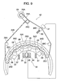
- Fig. 9 is a front view showing details of the safety device.
- the safety device is one for emergency stop when the second drive belt 24B breaks for some trouble.
- the second drive belt 24B breaks, all the rope drive pulleys 26 connected to the fourth belt drive pulleys 25D through the pulley connection shafts 27 become free in rotation. Therefore, whether the cages 3A to 3F travel or stop, for example, the cage 3A and the cage 3B become unbalanced in weight due to the weight of passengers, so that one of the cage 3A and the cage 3B falls and the other of them ascends.
- detection means for detecting breakage of the second drive belt 24B is provided on a second tension roller 28E positioned centrally. That is, a detection spring 30 comprising a cmpression spring is mounted to the tension roller 28E, and a detection switch 31 is provided on an axis of actuation of the detection spring 30.
- a movable iron core 35 is mounted on an intermediate portion of the brake friction pad 33.
- a solenoid coil 34 is arranged around the movable iron core 35.
- the solenoid coil 34 along with the movable iron core 35 is accommodated in a casing 36.
- Support springs 37 are arranged on both ends of the brake friction pad 33 and inside the arcuate shape of the pad to push the brake friction pad 33 toward the fourth belt drive pulleys 25D and the tension rollers 28.
- the brake friction pad 33, the support springs, the movable iron core 35, and the solenoid coil 34 constitute a brake device 32.
- the brake device 32 is electrically connected to the detection switch 31.
- the brake device constructed in this manner acts in the following manner.
- the restoring force of the detection spring 30 pushes the tension roller 28E toward the detection switch 31 to finally bring into contact with the detection switch 31.
- the detection switch 31 is pushed by the tension roller 28E, an input signal is generated in the detection switch 31 and an abnormality signal is transmitted to the brake device 32.
- the solenoid coil 34 Since the solenoid coil 34 is supplied with electric current at all times, it attracts the movable iron core 35 downward in the drawing in a normal state to define an air gap between the belt drive pulleys 25D and the brake friction pad 33.
- the brake device 32 stops supplying of electric current to the solenoid coil 34.
- the restoring forces of the support springs 37 act to push the brake friction pad 33 against the belt drive pulleys 25D.
- Rotation of the belt drive pulleys 25D is stopped by the brake friction pad 33. Since rotation of the belt drive pulleys 25D is stopped, rotation of the rope drive pulleys 26 connected directly thereto through the pulley connection shafts 27 is also stopped.
- frictional forces between the rope drive pulleys and the ropes make it possible to forcedly stop the cages.
- the safety device shown in the embodiment is provided in an elevator apparatus, it is possible to forcedly stop the cages even when such trouble as suspension of electric power or the like occurs, and to rapidly reopen the operation when electric current is again supplied after suspension of electric power.
- the brake friction pad 33 may be pushed against the rope drive pulleys 26 and the pulley connection shafts 27.
- the brake friction pad 33 may be modified in shape so that a single brake friction pad 33 can stop all the cage groups. In this case, when one cage group stops in emergency, the remaining cage groups are also stopped forcedly, so that it is possible to surely prevent collision among the cages.
- a brake device mounted on the drive motor 23 may be actuated when the belt on one side of the drive device breaks.
- a brake device for constraining rotation of the belt drive shaft 29, which connects between the two rope drive systems 41, 42 may be provided in the vicinity of the belt drive shaft 29 to stop rotation of the belt drive shaft 29 to constrain rotation of the rope drive pulleys 26.
- the six cages 3A to 3F are arranged in the same ascent and descent paths 1A, 1B to form three groups, four cages may be arranged in the same ascent and descent paths to form two groups, or eight cages may be arranged in the same ascent and descent paths to form four groups.
- a single drive motor drives two ropes on the front and back of the cages at a time, two drive motors may be used to drive respective ropes. In this case, it is necessary to synchronously drive the two drive motors.
- the drive motor 23 is arranged centrally above the ascent and descent paths 1A, 1B.
- ascent and descent paths are limited in height in relation to, for example, the layout of a building, or two drive motors drive cages of a single group, one of a pulley connection shaft and a drive motor shaft serve for a combined use.
- detection means for detecting breakage of the second drive belt is provided on the second tension roller, it may be provided on the third belt drive pulley 25C.
- the drive pulleys are arranged in an arcuate configuration, arcs, straight lines, elliptic curves, etc. may be combined to form a curve with less variation in curvature, in which case variation in a load on a rope is decreased in the ascent and descent paths and the reversal movement sections to result in an improvement in travel comfort.
- ascent and descent rails 9B may be arranged at an intermediate portion within a single ascent and descent path (an elevator shaft) to afford a divided use of the ascent and descent path. That is, it goes without saying that a construction may do to be able to arrange two cages side by side in a single elevator shaft.
- pairs of passenger cages are connected by ropes to form circulating loops, the loops are driven independently, and the loops are made oval in shape, so that it is possible to operate a multicar elevator stably. Also, since sudden fluctuation in a load on a rope is lessened, it is possible to reduce vibrations and noises.
Landscapes
- Engineering & Computer Science (AREA)
- Structural Engineering (AREA)
- Automation & Control Theory (AREA)
- Civil Engineering (AREA)
- Mechanical Engineering (AREA)
- Lift-Guide Devices, And Elevator Ropes And Cables (AREA)
- Types And Forms Of Lifts (AREA)
- Cage And Drive Apparatuses For Elevators (AREA)
Applications Claiming Priority (1)
| Application Number | Priority Date | Filing Date | Title |
|---|---|---|---|
| JP2004300904A JP4543868B2 (ja) | 2004-10-15 | 2004-10-15 | マルチカーエレベータ |
Publications (2)
| Publication Number | Publication Date |
|---|---|
| EP1647513A2 true EP1647513A2 (fr) | 2006-04-19 |
| EP1647513A3 EP1647513A3 (fr) | 2009-12-02 |
Family
ID=35810171
Family Applications (1)
| Application Number | Title | Priority Date | Filing Date |
|---|---|---|---|
| EP05007196A Withdrawn EP1647513A3 (fr) | 2004-10-15 | 2005-04-01 | Ascenseur multi-cabines |
Country Status (3)
| Country | Link |
|---|---|
| EP (1) | EP1647513A3 (fr) |
| JP (1) | JP4543868B2 (fr) |
| CN (1) | CN1760105B (fr) |
Cited By (6)
| Publication number | Priority date | Publication date | Assignee | Title |
|---|---|---|---|---|
| CN101172547B (zh) * | 2006-10-31 | 2010-10-27 | 株式会社日立制作所 | 电梯 |
| DE102014220966A1 (de) | 2014-10-16 | 2016-04-21 | Thyssenkrupp Elevator Ag | Verfahren zum Betreiben einer Transportanlage sowie entsprechende Transportanlage |
| US9481550B2 (en) | 2011-01-19 | 2016-11-01 | Smart Lifts, Llc | System having multiple cabs in an elevator shaft |
| US9522807B2 (en) | 2011-01-19 | 2016-12-20 | Smart Lifts, Llc | System of elevator cabs and counterweights that move independently in different sections of a hoistway |
| US10294074B2 (en) | 2015-07-31 | 2019-05-21 | Otis Elevator Company | Elevator recovery car |
| US11535493B2 (en) | 2017-08-17 | 2022-12-27 | Inventio Ag | Elevator system |
Families Citing this family (17)
| Publication number | Priority date | Publication date | Assignee | Title |
|---|---|---|---|---|
| JP4251376B2 (ja) * | 2006-03-19 | 2009-04-08 | 良三 太田 | 循環式エレベーター |
| JP4609395B2 (ja) * | 2006-07-28 | 2011-01-12 | 株式会社島津製作所 | 移動型x線撮影装置 |
| JP2008087954A (ja) * | 2006-10-05 | 2008-04-17 | Fujitec Co Ltd | エレベータ駆動装置 |
| JP4539682B2 (ja) * | 2007-06-12 | 2010-09-08 | 株式会社日立製作所 | マルチカーエレベーター |
| CN102145843A (zh) * | 2011-04-19 | 2011-08-10 | 张应刚 | 层进式循环运行的多轿厢电梯 |
| CN103130069A (zh) * | 2011-11-22 | 2013-06-05 | 常州市福驰电动车辆科技有限公司 | 一种多轿厢链式循环电梯-楼梯复合垂直交通系统 |
| CN108483182A (zh) * | 2016-08-23 | 2018-09-04 | 夏华萍 | 一种电梯系统 |
| CN106553942A (zh) * | 2017-01-22 | 2017-04-05 | 李先登 | 一种偶数轿箱高效节能电梯 |
| JP6762899B2 (ja) * | 2017-03-23 | 2020-09-30 | 株式会社日立製作所 | マルチカーエレベーター |
| US20200255261A1 (en) * | 2017-08-19 | 2020-08-13 | Libo Zhou | Smart multi-car elevator system |
| CN107673162B (zh) * | 2017-08-19 | 2019-03-19 | 周立波 | 一种智能多轿厢电梯 |
| CN109748177B (zh) * | 2017-11-08 | 2021-02-26 | 马庆 | 螺旋轨道电梯 |
| JP6966391B2 (ja) * | 2018-07-31 | 2021-11-17 | 株式会社日立製作所 | マルチカーエレベーター及びマルチカーエレベーターの制御方法 |
| JP7012615B2 (ja) * | 2018-07-31 | 2022-01-28 | 株式会社日立製作所 | マルチカーエレベーター及び乗りかご移動制御方法 |
| JP7261051B2 (ja) * | 2019-03-25 | 2023-04-19 | 株式会社日立製作所 | エレベーター |
| JP2022050826A (ja) * | 2020-09-18 | 2022-03-31 | 株式会社日立製作所 | マルチカーエレベーター |
| JP2022102576A (ja) * | 2020-12-25 | 2022-07-07 | 株式会社日立製作所 | 循環式マルチカーエレベーター及び循環式マルチカーエレベーター制御方法 |
Citations (5)
| Publication number | Priority date | Publication date | Assignee | Title |
|---|---|---|---|---|
| JPH0826629A (ja) * | 1994-07-20 | 1996-01-30 | Hitachi Ltd | 循環式エレベーター装置 |
| JPH0930756A (ja) * | 1995-07-17 | 1997-02-04 | Hitachi Ltd | つかみ替え式循環型エレベータ |
| DE29804749U1 (de) * | 1998-03-17 | 1998-08-06 | Czarnowski Gottfried Von | Personenlift zur Straßenüberquerung |
| US5857545A (en) * | 1997-03-20 | 1999-01-12 | Otis Elevator Company | Elevator system with overlapped roped-coupler segments |
| WO2002059030A1 (fr) * | 2001-06-14 | 2002-08-01 | Nicolas Vazquez Alonso | Systeme d'ascenseurs a circulation continue pour batiments |
Family Cites Families (6)
| Publication number | Priority date | Publication date | Assignee | Title |
|---|---|---|---|---|
| JPS6071488A (ja) * | 1983-09-28 | 1985-04-23 | 三菱電機株式会社 | エレベータの駆動装置 |
| JP2602311B2 (ja) * | 1989-01-18 | 1997-04-23 | 株式会社日立製作所 | 乗客コンベアの手摺ベルト駆動装置 |
| JP3294639B2 (ja) * | 1992-07-14 | 2002-06-24 | 日本板硝子株式会社 | 板状体の往復搬送装置 |
| JPH1059659A (ja) * | 1996-08-22 | 1998-03-03 | Tetsuzo Shibuya | エレベーター |
| JP3469780B2 (ja) * | 1998-05-22 | 2003-11-25 | 富士変速機株式会社 | 循環式エレベータ |
| JP2001139270A (ja) * | 1999-11-11 | 2001-05-22 | Mitsubishi Electric Corp | 乗客コンベヤーの手摺駆動装置 |
-
2004
- 2004-10-15 JP JP2004300904A patent/JP4543868B2/ja active Active
-
2005
- 2005-04-01 CN CN 200510060193 patent/CN1760105B/zh active Active
- 2005-04-01 EP EP05007196A patent/EP1647513A3/fr not_active Withdrawn
Patent Citations (5)
| Publication number | Priority date | Publication date | Assignee | Title |
|---|---|---|---|---|
| JPH0826629A (ja) * | 1994-07-20 | 1996-01-30 | Hitachi Ltd | 循環式エレベーター装置 |
| JPH0930756A (ja) * | 1995-07-17 | 1997-02-04 | Hitachi Ltd | つかみ替え式循環型エレベータ |
| US5857545A (en) * | 1997-03-20 | 1999-01-12 | Otis Elevator Company | Elevator system with overlapped roped-coupler segments |
| DE29804749U1 (de) * | 1998-03-17 | 1998-08-06 | Czarnowski Gottfried Von | Personenlift zur Straßenüberquerung |
| WO2002059030A1 (fr) * | 2001-06-14 | 2002-08-01 | Nicolas Vazquez Alonso | Systeme d'ascenseurs a circulation continue pour batiments |
Cited By (9)
| Publication number | Priority date | Publication date | Assignee | Title |
|---|---|---|---|---|
| CN101172547B (zh) * | 2006-10-31 | 2010-10-27 | 株式会社日立制作所 | 电梯 |
| US9481550B2 (en) | 2011-01-19 | 2016-11-01 | Smart Lifts, Llc | System having multiple cabs in an elevator shaft |
| US9522807B2 (en) | 2011-01-19 | 2016-12-20 | Smart Lifts, Llc | System of elevator cabs and counterweights that move independently in different sections of a hoistway |
| DE102014220966A1 (de) | 2014-10-16 | 2016-04-21 | Thyssenkrupp Elevator Ag | Verfahren zum Betreiben einer Transportanlage sowie entsprechende Transportanlage |
| WO2016058940A1 (fr) | 2014-10-16 | 2016-04-21 | Thyssenkrupp Elevator Ag | Procédé de fonctionnement d'un système de transport et système de transport correspondant |
| US10703603B2 (en) | 2014-10-16 | 2020-07-07 | Thyssenkrupp Elevator Ag | Operating a cyclical transport system based on an equal cycle time |
| US10294074B2 (en) | 2015-07-31 | 2019-05-21 | Otis Elevator Company | Elevator recovery car |
| US11535493B2 (en) | 2017-08-17 | 2022-12-27 | Inventio Ag | Elevator system |
| US11623845B2 (en) * | 2017-08-17 | 2023-04-11 | Inventio Ag | Elevator system |
Also Published As
| Publication number | Publication date |
|---|---|
| CN1760105A (zh) | 2006-04-19 |
| CN1760105B (zh) | 2012-04-18 |
| JP2006111408A (ja) | 2006-04-27 |
| JP4543868B2 (ja) | 2010-09-15 |
| EP1647513A3 (fr) | 2009-12-02 |
Similar Documents
| Publication | Publication Date | Title |
|---|---|---|
| EP1647513A2 (fr) | Ascenseur multi-cabines | |
| KR101446380B1 (ko) | 케이블철도시스템 | |
| US9102502B2 (en) | Double-deck elevator | |
| JP2008156116A (ja) | 昇降路内で相互に上下に配置された2台のエレベータケージを有するエレベータ | |
| JP5330666B2 (ja) | 昇降路内に2つのエレベータケージを互いに上下に配置して備えるエレベータ | |
| JP5031577B2 (ja) | 昇降路内に複数のかごを有するエレベータシステム | |
| US10875743B2 (en) | Rope-climbing self propelled elevator system | |
| WO2002038482A1 (fr) | Dispositif de cabine pour ascenseurs a double cabine | |
| CN103298727A (zh) | 电梯设备 | |
| US20120168278A1 (en) | People mover and method | |
| JP5693723B2 (ja) | ダブルデッキエレベータ | |
| JP2016150815A (ja) | 乗客コンベア | |
| JPWO2007122702A1 (ja) | エレベータ装置 | |
| CN104418212B (zh) | 电梯 | |
| JP2008520514A5 (fr) | ||
| JP2005132527A (ja) | マルチカーエレベータ | |
| EP1535875B1 (fr) | Dispositif d'ascenseur | |
| US7913818B2 (en) | Elevator installation in a building with at least one transfer floor | |
| US9988243B2 (en) | Elevator system | |
| US10023436B2 (en) | Drive with multiple looping for an elevator installation | |
| JP4223613B2 (ja) | 自走式エレベータ装置 | |
| CN113581976A (zh) | 用于电梯轿厢的导向装置和电梯系统 | |
| JP7100304B1 (ja) | 調速機及びエレベータ | |
| JP5676556B2 (ja) | エレベータ装置 | |
| WO2012127682A1 (fr) | Ascenseur à étages multiples |
Legal Events
| Date | Code | Title | Description |
|---|---|---|---|
| PUAI | Public reference made under article 153(3) epc to a published international application that has entered the european phase |
Free format text: ORIGINAL CODE: 0009012 |
|
| AK | Designated contracting states |
Kind code of ref document: A2 Designated state(s): AT BE BG CH CY CZ DE DK EE ES FI FR GB GR HU IE IS IT LI LT LU MC NL PL PT RO SE SI SK TR |
|
| AX | Request for extension of the european patent |
Extension state: AL BA HR LV MK YU |
|
| 17P | Request for examination filed |
Effective date: 20090623 |
|
| PUAL | Search report despatched |
Free format text: ORIGINAL CODE: 0009013 |
|
| AK | Designated contracting states |
Kind code of ref document: A3 Designated state(s): AT BE BG CH CY CZ DE DK EE ES FI FR GB GR HU IE IS IT LI LT LU MC NL PL PT RO SE SI SK TR |
|
| AX | Request for extension of the european patent |
Extension state: AL BA HR LV MK YU |
|
| AKX | Designation fees paid |
Designated state(s): DE FR |
|
| 17Q | First examination report despatched |
Effective date: 20121105 |
|
| STAA | Information on the status of an ep patent application or granted ep patent |
Free format text: STATUS: THE APPLICATION IS DEEMED TO BE WITHDRAWN |
|
| 18D | Application deemed to be withdrawn |
Effective date: 20130418 |