EP1642125B1 - Biosensor with multiple electrical functionalities - Google Patents
Biosensor with multiple electrical functionalities Download PDFInfo
- Publication number
- EP1642125B1 EP1642125B1 EP04776796.7A EP04776796A EP1642125B1 EP 1642125 B1 EP1642125 B1 EP 1642125B1 EP 04776796 A EP04776796 A EP 04776796A EP 1642125 B1 EP1642125 B1 EP 1642125B1
- Authority
- EP
- European Patent Office
- Prior art keywords
- biosensor
- sample
- electrode
- strip
- receiving chamber
- Prior art date
- Legal status (The legal status is an assumption and is not a legal conclusion. Google has not performed a legal analysis and makes no representation as to the accuracy of the status listed.)
- Not-in-force
Links
- 238000005259 measurement Methods 0.000 claims description 43
- 239000012530 fluid Substances 0.000 claims description 24
- 239000012491 analyte Substances 0.000 claims description 22
- 239000003153 chemical reaction reagent Substances 0.000 claims description 15
- 238000003780 insertion Methods 0.000 claims description 4
- 230000037431 insertion Effects 0.000 claims description 4
- 239000000523 sample Substances 0.000 description 95
- 238000012360 testing method Methods 0.000 description 62
- 239000000758 substrate Substances 0.000 description 38
- 210000004369 blood Anatomy 0.000 description 18
- 239000008280 blood Substances 0.000 description 18
- 238000013459 approach Methods 0.000 description 17
- 238000000034 method Methods 0.000 description 16
- 238000000576 coating method Methods 0.000 description 15
- 238000003491 array Methods 0.000 description 11
- 238000004519 manufacturing process Methods 0.000 description 10
- 239000000463 material Substances 0.000 description 10
- WQZGKKKJIJFFOK-GASJEMHNSA-N Glucose Natural products OC[C@H]1OC(O)[C@H](O)[C@@H](O)[C@@H]1O WQZGKKKJIJFFOK-GASJEMHNSA-N 0.000 description 9
- 239000008103 glucose Substances 0.000 description 9
- 238000010248 power generation Methods 0.000 description 9
- 125000006850 spacer group Chemical group 0.000 description 9
- 239000011248 coating agent Substances 0.000 description 8
- 239000011800 void material Substances 0.000 description 7
- 230000001965 increasing effect Effects 0.000 description 6
- 229920000642 polymer Polymers 0.000 description 6
- 239000000126 substance Substances 0.000 description 6
- 239000000243 solution Substances 0.000 description 5
- 210000004027 cell Anatomy 0.000 description 4
- 238000012937 correction Methods 0.000 description 4
- 230000006870 function Effects 0.000 description 4
- WEVYAHXRMPXWCK-UHFFFAOYSA-N Acetonitrile Chemical compound CC#N WEVYAHXRMPXWCK-UHFFFAOYSA-N 0.000 description 3
- 230000008901 benefit Effects 0.000 description 3
- 239000003990 capacitor Substances 0.000 description 3
- 150000001875 compounds Chemical class 0.000 description 3
- 230000000875 corresponding effect Effects 0.000 description 3
- 238000013461 design Methods 0.000 description 3
- 238000002848 electrochemical method Methods 0.000 description 3
- 238000005516 engineering process Methods 0.000 description 3
- 238000002474 experimental method Methods 0.000 description 3
- 238000005534 hematocrit Methods 0.000 description 3
- 239000012528 membrane Substances 0.000 description 3
- -1 polyparaphenylene vinylene Polymers 0.000 description 3
- 238000007650 screen-printing Methods 0.000 description 3
- 238000012546 transfer Methods 0.000 description 3
- BPYKTIZUTYGOLE-IFADSCNNSA-N Bilirubin Chemical compound N1C(=O)C(C)=C(C=C)\C1=C\C1=C(C)C(CCC(O)=O)=C(CC2=C(C(C)=C(\C=C/3C(=C(C=C)C(=O)N\3)C)N2)CCC(O)=O)N1 BPYKTIZUTYGOLE-IFADSCNNSA-N 0.000 description 2
- 239000004593 Epoxy Substances 0.000 description 2
- 230000009471 action Effects 0.000 description 2
- 238000004458 analytical method Methods 0.000 description 2
- 210000001124 body fluid Anatomy 0.000 description 2
- 239000002800 charge carrier Substances 0.000 description 2
- HVYWMOMLDIMFJA-DPAQBDIFSA-N cholesterol Chemical compound C1C=C2C[C@@H](O)CC[C@]2(C)[C@@H]2[C@@H]1[C@@H]1CC[C@H]([C@H](C)CCCC(C)C)[C@@]1(C)CC2 HVYWMOMLDIMFJA-DPAQBDIFSA-N 0.000 description 2
- 239000004020 conductor Substances 0.000 description 2
- 238000003869 coulometry Methods 0.000 description 2
- 239000008367 deionised water Substances 0.000 description 2
- 229910021641 deionized water Inorganic materials 0.000 description 2
- 238000001514 detection method Methods 0.000 description 2
- WHELTKFSBJNBMQ-UHFFFAOYSA-L dichlororuthenium;2-pyridin-2-ylpyridine;hexahydrate Chemical compound O.O.O.O.O.O.[Cl-].[Cl-].[Ru+2].N1=CC=CC=C1C1=CC=CC=N1.N1=CC=CC=C1C1=CC=CC=N1.N1=CC=CC=C1C1=CC=CC=N1 WHELTKFSBJNBMQ-UHFFFAOYSA-L 0.000 description 2
- 230000000694 effects Effects 0.000 description 2
- 238000000840 electrochemical analysis Methods 0.000 description 2
- 239000010408 film Substances 0.000 description 2
- 230000003993 interaction Effects 0.000 description 2
- 230000002452 interceptive effect Effects 0.000 description 2
- 238000000608 laser ablation Methods 0.000 description 2
- 238000000691 measurement method Methods 0.000 description 2
- 230000003287 optical effect Effects 0.000 description 2
- 229920000728 polyester Polymers 0.000 description 2
- 230000004044 response Effects 0.000 description 2
- 150000003304 ruthenium compounds Chemical class 0.000 description 2
- 230000000007 visual effect Effects 0.000 description 2
- XLYOFNOQVPJJNP-UHFFFAOYSA-N water Chemical compound O XLYOFNOQVPJJNP-UHFFFAOYSA-N 0.000 description 2
- MAGFQRLKWCCTQJ-UHFFFAOYSA-N 4-ethenylbenzenesulfonic acid Chemical class OS(=O)(=O)C1=CC=C(C=C)C=C1 MAGFQRLKWCCTQJ-UHFFFAOYSA-N 0.000 description 1
- 102000004190 Enzymes Human genes 0.000 description 1
- 108090000790 Enzymes Proteins 0.000 description 1
- 108010023302 HDL Cholesterol Proteins 0.000 description 1
- DGAQECJNVWCQMB-PUAWFVPOSA-M Ilexoside XXIX Chemical compound C[C@@H]1CC[C@@]2(CC[C@@]3(C(=CC[C@H]4[C@]3(CC[C@@H]5[C@@]4(CC[C@@H](C5(C)C)OS(=O)(=O)[O-])C)C)[C@@H]2[C@]1(C)O)C)C(=O)O[C@H]6[C@@H]([C@H]([C@@H]([C@H](O6)CO)O)O)O.[Na+] DGAQECJNVWCQMB-PUAWFVPOSA-M 0.000 description 1
- 239000004642 Polyimide Substances 0.000 description 1
- XUIMIQQOPSSXEZ-UHFFFAOYSA-N Silicon Chemical compound [Si] XUIMIQQOPSSXEZ-UHFFFAOYSA-N 0.000 description 1
- 229920001646 UPILEX Polymers 0.000 description 1
- LEHOTFFKMJEONL-UHFFFAOYSA-N Uric Acid Chemical compound N1C(=O)NC(=O)C2=C1NC(=O)N2 LEHOTFFKMJEONL-UHFFFAOYSA-N 0.000 description 1
- TVWHNULVHGKJHS-UHFFFAOYSA-N Uric acid Natural products N1C(=O)NC(=O)C2NC(=O)NC21 TVWHNULVHGKJHS-UHFFFAOYSA-N 0.000 description 1
- 238000002835 absorbance Methods 0.000 description 1
- 230000006978 adaptation Effects 0.000 description 1
- 239000000853 adhesive Substances 0.000 description 1
- 230000001070 adhesive effect Effects 0.000 description 1
- 230000004075 alteration Effects 0.000 description 1
- 230000003466 anti-cipated effect Effects 0.000 description 1
- QVGXLLKOCUKJST-UHFFFAOYSA-N atomic oxygen Chemical compound [O] QVGXLLKOCUKJST-UHFFFAOYSA-N 0.000 description 1
- 239000012472 biological sample Substances 0.000 description 1
- 210000000601 blood cell Anatomy 0.000 description 1
- 238000009529 body temperature measurement Methods 0.000 description 1
- 238000006243 chemical reaction Methods 0.000 description 1
- 235000012000 cholesterol Nutrition 0.000 description 1
- 239000008199 coating composition Substances 0.000 description 1
- 239000000470 constituent Substances 0.000 description 1
- 238000011109 contamination Methods 0.000 description 1
- 239000013068 control sample Substances 0.000 description 1
- 230000002596 correlated effect Effects 0.000 description 1
- 230000007423 decrease Effects 0.000 description 1
- 230000003247 decreasing effect Effects 0.000 description 1
- 230000007547 defect Effects 0.000 description 1
- 230000001627 detrimental effect Effects 0.000 description 1
- 206010012601 diabetes mellitus Diseases 0.000 description 1
- 238000003745 diagnosis Methods 0.000 description 1
- 201000010099 disease Diseases 0.000 description 1
- 208000037265 diseases, disorders, signs and symptoms Diseases 0.000 description 1
- 238000009429 electrical wiring Methods 0.000 description 1
- 238000000835 electrochemical detection Methods 0.000 description 1
- 238000005868 electrolysis reaction Methods 0.000 description 1
- 230000002708 enhancing effect Effects 0.000 description 1
- 230000007613 environmental effect Effects 0.000 description 1
- 210000003743 erythrocyte Anatomy 0.000 description 1
- 230000005284 excitation Effects 0.000 description 1
- 235000013305 food Nutrition 0.000 description 1
- 238000011990 functional testing Methods 0.000 description 1
- 239000011521 glass Substances 0.000 description 1
- PCHJSUWPFVWCPO-UHFFFAOYSA-N gold Chemical compound [Au] PCHJSUWPFVWCPO-UHFFFAOYSA-N 0.000 description 1
- 229910052737 gold Inorganic materials 0.000 description 1
- 239000010931 gold Substances 0.000 description 1
- 238000005286 illumination Methods 0.000 description 1
- 230000001771 impaired effect Effects 0.000 description 1
- AMGQUBHHOARCQH-UHFFFAOYSA-N indium;oxotin Chemical compound [In].[Sn]=O AMGQUBHHOARCQH-UHFFFAOYSA-N 0.000 description 1
- 239000000976 ink Substances 0.000 description 1
- 238000001307 laser spectroscopy Methods 0.000 description 1
- 150000002632 lipids Chemical class 0.000 description 1
- 230000007257 malfunction Effects 0.000 description 1
- 238000013507 mapping Methods 0.000 description 1
- 239000011159 matrix material Substances 0.000 description 1
- 230000000116 mitigating effect Effects 0.000 description 1
- 239000000203 mixture Substances 0.000 description 1
- 238000012986 modification Methods 0.000 description 1
- 230000004048 modification Effects 0.000 description 1
- 229910052760 oxygen Inorganic materials 0.000 description 1
- 239000001301 oxygen Substances 0.000 description 1
- 238000000206 photolithography Methods 0.000 description 1
- 229920001467 poly(styrenesulfonates) Polymers 0.000 description 1
- 239000011112 polyethylene naphthalate Substances 0.000 description 1
- 229920001721 polyimide Polymers 0.000 description 1
- 230000008569 process Effects 0.000 description 1
- 238000003672 processing method Methods 0.000 description 1
- 230000001737 promoting effect Effects 0.000 description 1
- 238000001055 reflectance spectroscopy Methods 0.000 description 1
- 230000035945 sensitivity Effects 0.000 description 1
- 238000000926 separation method Methods 0.000 description 1
- 229910052710 silicon Inorganic materials 0.000 description 1
- 239000010703 silicon Substances 0.000 description 1
- 229910052708 sodium Inorganic materials 0.000 description 1
- 239000011734 sodium Substances 0.000 description 1
- 238000001228 spectrum Methods 0.000 description 1
- 235000000346 sugar Nutrition 0.000 description 1
- 150000008163 sugars Chemical class 0.000 description 1
- 239000010409 thin film Substances 0.000 description 1
- 150000003626 triacylglycerols Chemical class 0.000 description 1
- 229940116269 uric acid Drugs 0.000 description 1
- 238000012795 verification Methods 0.000 description 1
- 238000009736 wetting Methods 0.000 description 1
Images


Classifications
-
- G—PHYSICS
- G01—MEASURING; TESTING
- G01N—INVESTIGATING OR ANALYSING MATERIALS BY DETERMINING THEIR CHEMICAL OR PHYSICAL PROPERTIES
- G01N27/00—Investigating or analysing materials by the use of electric, electrochemical, or magnetic means
- G01N27/26—Investigating or analysing materials by the use of electric, electrochemical, or magnetic means by investigating electrochemical variables; by using electrolysis or electrophoresis
- G01N27/28—Electrolytic cell components
- G01N27/30—Electrodes, e.g. test electrodes; Half-cells
- G01N27/327—Biochemical electrodes, e.g. electrical or mechanical details for in vitro measurements
- G01N27/3271—Amperometric enzyme electrodes for analytes in body fluids, e.g. glucose in blood
- G01N27/3272—Test elements therefor, i.e. disposable laminated substrates with electrodes, reagent and channels
-
- G—PHYSICS
- G01—MEASURING; TESTING
- G01N—INVESTIGATING OR ANALYSING MATERIALS BY DETERMINING THEIR CHEMICAL OR PHYSICAL PROPERTIES
- G01N27/00—Investigating or analysing materials by the use of electric, electrochemical, or magnetic means
- G01N27/26—Investigating or analysing materials by the use of electric, electrochemical, or magnetic means by investigating electrochemical variables; by using electrolysis or electrophoresis
- G01N27/28—Electrolytic cell components
- G01N27/30—Electrodes, e.g. test electrodes; Half-cells
-
- C—CHEMISTRY; METALLURGY
- C12—BIOCHEMISTRY; BEER; SPIRITS; WINE; VINEGAR; MICROBIOLOGY; ENZYMOLOGY; MUTATION OR GENETIC ENGINEERING
- C12M—APPARATUS FOR ENZYMOLOGY OR MICROBIOLOGY; APPARATUS FOR CULTURING MICROORGANISMS FOR PRODUCING BIOMASS, FOR GROWING CELLS OR FOR OBTAINING FERMENTATION OR METABOLIC PRODUCTS, i.e. BIOREACTORS OR FERMENTERS
- C12M1/00—Apparatus for enzymology or microbiology
-
- C—CHEMISTRY; METALLURGY
- C12—BIOCHEMISTRY; BEER; SPIRITS; WINE; VINEGAR; MICROBIOLOGY; ENZYMOLOGY; MUTATION OR GENETIC ENGINEERING
- C12Q—MEASURING OR TESTING PROCESSES INVOLVING ENZYMES, NUCLEIC ACIDS OR MICROORGANISMS; COMPOSITIONS OR TEST PAPERS THEREFOR; PROCESSES OF PREPARING SUCH COMPOSITIONS; CONDITION-RESPONSIVE CONTROL IN MICROBIOLOGICAL OR ENZYMOLOGICAL PROCESSES
- C12Q1/00—Measuring or testing processes involving enzymes, nucleic acids or microorganisms; Compositions therefor; Processes of preparing such compositions
- C12Q1/001—Enzyme electrodes
-
- G—PHYSICS
- G01—MEASURING; TESTING
- G01N—INVESTIGATING OR ANALYSING MATERIALS BY DETERMINING THEIR CHEMICAL OR PHYSICAL PROPERTIES
- G01N33/00—Investigating or analysing materials by specific methods not covered by groups G01N1/00 - G01N31/00
- G01N33/48—Biological material, e.g. blood, urine; Haemocytometers
- G01N33/483—Physical analysis of biological material
- G01N33/487—Physical analysis of biological material of liquid biological material
Definitions
- the present invention relates generally to devices for measuring analytes from biological samples, such as from a sample of bodily fluid. More particularly, the present invention relates to electrically operable biosensors.
- optical methods generally involve absorbance, reflectance or laser spectroscopy to observe the spectrum shift in the fluid caused by the concentration of the analytes, typically in conjunction with a reagent that produces a known color when combined with the analyte.
- Electrochemical methods generally rely upon the correlation between a charge-transfer or charge-movement property of the blood sample (e.g., current, interfacial potential, impedance, conductance, and the like) and the concentration of the analyte, typically in conjunction with a reagent that produces or modifies charge-carriers when combined with the analyte.
- Document WO00/33063 describes a biosensor comprising a biosensor body having a sample receiving chamber as indicated in the preamble of claim 1.
- An important limitation of electrochemical methods of measuring the concentration of a chemical in blood is the effect of confounding variables on the impedance of a blood sample. For example, the geometry of the blood sample must correspond closely to that upon which the impedance-to-concentration mapping function is based.
- the geometry of the blood sample is typically controlled by a sample-receiving chamber of the testing apparatus in which the fluid sample is received and held during its analysis.
- the blood sample is typically placed onto a disposable test strip or biosensor that plugs into the meter.
- the test strip may have a sample chamber to define the geometry of the sample.
- the effects of sample geometry may be limited by assuring an effectively infinite sample size.
- the electrodes used for measuring the analyte may be spaced closely enough so that a drop of blood on the test strip extends substantially beyond the electrodes in all directions.
- typically one or more dose sufficiency electrodes are used to assure that a sufficient amount of sample has been introduced into the sample receiving chamber to assure an accurate test result.
- hematocrit concentration of red blood cells
- other chemicals can influence the transfer of charge carriers through a blood sample, including, for example, uric acid, bilirubin, and oxygen, thereby causing error in the measurement of glucose.
- Efforts to improve test strips have been mainly directed to making them smaller, faster, and require less sample volume. For example, it is desirable for electrochemical biosensors to be able to analyze as small a sample as possible, and it is therefore necessary to minimize the size of their parts, including the electrodes.
- screen-printing, laser scribing, and photolithography techniques have been used to form miniaturized electrodes. These methods are undesirably time-consuming, however, and screen-printing or laser scribing technologies pose limitations on the edge quality of the electrical patterns formed, such that gap widths between electrical elements normally must be 75 microns or more. Further, some of these techniques make it unworkable on a commercial scale to remove more than a small fraction, e.g., more than 5-10% of the conductive material from a substrate to form an electrical pattern.
- the electrode structures in available electrochemical test strips made by these techniques typically have one or perhaps two pairs of electrodes, and the measurements obtained by these electrode structures are quite sensitive to the interferents discussed above.
- the signal produced by the analyte desired to be analyzed must be deconvoluted from the noise produced by the interfering substances.
- Many approaches have been employed to attenuate/mitigate interference or to otherwise compensate or correct a measured value. Often, multiple design solutions are employed to adequately compensate for the sensitivities associated with the chosen measurement method.
- One approach involves removing interfering materials such as blood cells from the fluid sample before it reaches the electrodes by using perm-selective and/or size-selective membranes, filters or coatings. Multiple layers of membranes are often laminated together to achieve the ultimate goal of delivering a fluid to the electrodes which contains only low levels of interferents.
- this approach suffers from incremental costs of goods, viz., coatings and membranes that must often be pre-treated prior to assembly. It also incurs additional manufacturing process steps that further increase manufacturing cost and complexity while decreasing the speed of manufacture.
- This approach addresses the attenuation problem by increasing the complexity and cost of the test strip, thereby reducing the burden of the meter which reads the strips.
- the present invention provides a biosensor having multiple electrical functionalities located both within and outside of the measurement zone in which the fluid sample is interrogated. Incredibly small and complex electrical patterns with high quality edges provide electrical functionalities in the biosensor and also provide the electrical wiring for the various other electrical devices provided in the inventive biosensor.
- biosensors of the present invention may be provided with a user interface zone, a digital device zone and/or a power generation zone.
- the inventors of the present invention have taken an entirely different approach than the schemes discussed above for mitigating interference or otherwise correcting a value measured by a test strip.
- Their novel approach focuses upon (1) enhancing the quality and complexity of the electrical patterns formed on a biosensor, (2) significantly reducing the size of these electrical patterns, and at the same time (3) increasing production speeds while (4) reducing manufacturing costs. This approach decreases the computational burden and associated cost of the instruments that read the strips while at the same time adding accurate yet cost-effective functionalities to the biosensors themselves.
- the present invention provides a biosensor for analyzing a fluid as defined in claim 1. Any number of occurrences can constitute a "triggering event,” including but not limited to insertion of the strip into a meter, a sufficient size dose being received in the sample receiving chamber, malfunction of test, non-functional test strip, etc. Furthermore, there may be a delay between the occurrence of the triggering event and the signal generator emitting the signal.
- the signal generator comprises an electrode set on which the OLED is coated. More preferably, the electrode set comprises a micro-electrode array with at least two electrode fingers having a gap of less than about 5 microns between them.
- the biosensor also may include a power generation zone in which is disposed a power generator. More preferably, the biosensor additionally includes a digital information zone in which is disposed at least one digital device.
- test strips embodied by the present invention provide for testing of an analyte in a bodily or other fluid using multiple electrode functionalities that are provided on board the test strips.
- multiple electrode sets can be formed which perform the same or different functions.
- the novel electrical features of the embodiments disclosed herein extend beyond the concept of "measurement functionalities," however. Indeed, it is helpful to view test strips embodying the present invention as having individual "zones," each zone including electrical devices having a specific functionality.
- test strips disclosed herein may provide user interface, digital, and power generation zones that have been hitherto unavailable in test strip architecture.
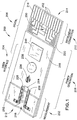
- strip 200 defines a test strip body that generally has several zones, including a measurement zone 202, a user interface zone 204, a power generation zone 206, a digital device zone 208 and an instrument connection zone 210.
- the zones are not limited to specific locations on a given test strip 200. Instead, the locations of the various zones will normally overlap to varying degrees as shown or may be discontinuous, occupying two or more different regions of the test strip body.
- Each zone generally has included therein electrical devices that perform a specific type or class of function.
- the electrical devices included in the measurement zone typically have functionalities related to the measurement (or correction of measurement) of the fluid sample being interrogated.
- these electrical devices include macro and micro-electrode sets, dose detection electrodes, sample sufficiency electrodes, temperature correction or temperature measurement electrodes, thermistors and the like. While the measurement zone is illustrated at a dosing end 212 of the strip, it should be understood that the measurement zone may alternatively occupy other locations on the strip, e.g., a side of the strip, as is known in the art.
- the electrical devices in the user interface zone typically are electrically driven signal generators which emit a visible signal upon occurrence of a "triggering event.”
- the signal generator may be a light that illuminates or turns off after a sufficiently sized sample has been received in the measurement zone, the latter event being the "triggering event.”
- the user interface zone is in some embodiments electrically wired to the measurement zone and/or other zones of the test strip.
- the power generation zone includes one or more power generators that provide power to one or more other electrical devices disposed on or in the test strip.
- the power generator comprises a battery, but it could also comprise a capacitor or even a solar cell, depending upon the power requirements of the electrical device the power generator is going to drive and the specific functionality of that device.
- Digital devices such as RFID tags, integrated circuits and the like are disposed within the digital zone and may be wired to the electrical pattern.
- the electrical pattern that is disposed in the digital zone is itself encoded with digital information and thus comprises yet another type of digital device.
- the instrument connection zone includes electrical devices, typically contact pads, that electrically link to an instrument (not shown) which includes driving circuitry and metering circuitry.
- the driving circuitry provides a known current and/or potential through contacts 216 and monitors the current and/or voltage response over a period of time.
- the metering circuitry correlates the monitored current, impedance and voltage response to estimated analyte concentration or other aspect of the analyte.
- the instrument connection zone is preferably disposed on a meter insertion end 214 of the strip, this need not necessarily be the case.
- the instrument zone could be located on a side of the strip or could be located on the end as shown, but could also include contact pads that are disposed at various locations on the top, bottom or sides of the test strip.
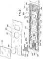
- strip 200 is generally of a laminar structure and includes three primary layers.
- the base substrate layer 220 is generally a flexible polymeric material such as polyester, especially high temperature polyester materials; polyethylene naphthalate (PEN); and polyimide, or mixtures of two or more of these.
- a particularly preferred base substrate material is a 10 mil thick MELINEX® 329 layer available from duPont.
- Substrate 220 is initially coated with a conductive material such as a 50 nm layer of gold, and the complex electrical pattern 222 can be then formed therefrom by broad field laser ablation. Materials for the specific biosensor layers and the method of assembling those materials is described in the Slot Vent Opening application, also incorporated above.
- the electrical pattern 222 includes contacts or contact pads 216, which, as described above, can be electrically linked to an instrument that reads strip 200. Traces 223 run lengthwise along strip 200 and are typically used to connect electrical devices to the contact pads 216 or to connect two or more electrical devices on or in strip 200 together.
- substrate 220 includes a measuring electrode set 228 coated by a reagent 229 and a sample sufficiency electrode set 230. These electrode sets are connected to their respective contact pads by traces 230 and 232 and in turn through traces 223 as shown.
- User interface devices comprising L-shaped micro-electrode arrays 224 are formed on base substrate 220 and are coated with organic light emitting diodes ("OLEDs") 226, which illuminate upon a voltage being provided across arrays 224. The voltage is applied or removed upon or after the occurrence of a triggering event, as described in more detail below.
- OLEDs organic light emitting diodes
- micro-electrode set 234 formed on substrate 220 is coated with a second OLED 236 that illuminates or turns off upon the occurrence of the same or a different triggering event, as is also described in more detail below.
- a power generator 238 is provided on strip 200 and can be used to power various other electrical devices present on the strip, as explained below. Many suitable power generators are commercially available and can be employed as power generator 238, but power generator 238 should preferably be formed as a small and especially thin material so as not to significantly increase the thickness of test strip 200.
- Test strip 200 includes digital device 246, which is shown in Fig. 2 wired to power generator 238 by traces 248.
- Digital device 246 may be an integrated circuit, an RFID tag or other digital device, as described in more detail below. Further, a portion of the electrical pattern may comprise a digital device 250, as explained in more detail below.
- Spacer layer 256 Laminated to base substrate 220 is a spacer layer 256, formed, e.g., from a 4 or 5 mil thick Melinex® 329, 339 or 453 material available from DuPont Teijin Films. In certain embodiments, particularly those including light emitters such as OLEDs 226 and 236, it is preferable that the spacer layer material be clear or translucent so that the OLEDs are visible when lit.
- the Melinex® 453 material works well for this purpose.
- Spacer layer 256 forms a void 258 that defines the height and perimeter of the sample receiving chamber 218 ( Fig. 1 ). The precise volume of the sample receiving chamber is defined in the Slot Vent Opening application, which was incorporated above.
- Spacer layer 256 also includes "cut-outs" 260 and 261 that are sized to receive digital device 246 and power generator 238, respectively. These devices will typically be thicker than the spacer layer, such that they may protrude slightly from the top of strip 200 as shown in Fig. 1 .
- a covering layer 262 overlies and is laminated to spacer layer 256.
- Covering layer 262 is also preferably made from a transparent Melinex® film that is about 4-5 mils thick. Covering layer 262 overlies most of void 258 and forms the ceiling or top boundary for sample receiving camber 218. The cover terminates short of the full length of void 258 and thereby forms a vent opening 264 as shown. Vent 264 allows air to be displaced from chamber 218 as fluid sample enters it.
- OLED coatings 226 and 236 are visible when lit through the covering and spacer layers.
- cover layer 262 may extend further toward meter insertion end 214, such that it is coextensive with layer 256.
- the cover 262 would then be formed with a hole overlying the void 258 to form the vent.
- the cover could be formed in two pieces forming a gap therebetween.
- This longer spacer layer may also include cut-outs that align with cutouts 260 and 261 and reduce the extent to which devices 238 and 246 protrude from strip 200.
- electrical devices in the user interface or power generation zones it is preferable for electrical devices in the user interface or power generation zones to be sufficiently thin such that they can be covered by covering layer 262 for protection from electromagnetic interference.
- the electrical patterns for use with embodiments incorporating the present invention are typically formed by broad field laser ablation. This method allows several electrical functionalities to be located within and outside of measurement zone 202 -- with room to spare on an already very small test strip.
- arrow 240 in Fig. 2 represents the approximate width of strip 200, which is about 9 mm in the illustrated embodiment.
- the strip illustrated in Figs. 1 and 2 is preferably about 33 - 38 mm in length.
- Arrows 242 illustrate the distance from the edge of the strip to the innermost trace 223, and this width can be configured to be about 1 mm or even as small as about 0.2 mm.
- width 244 which is the width available for components such as power generator 238 and digital device 246, can be about 8 mm or more for a 9 mm wide strip having ten electrical traces running lengthwise along it.
- electrical patterns embodied by the present invention while complex, can nonetheless be advantageously configured into a relatively small space, such that ample room remains for other devices having relatively large footprints to be placed on the strip.
- the measurement zone 202 includes a sample receiving chamber 218 whose periphery is approximately indicated in Fig. 2 by dashed line 266.
- Macro-electrode array 228 includes a working electrode and a counter electrode, each having one or more interdigitated fingers as shown. Electrode set 228 estimates the concentration of analyte based upon the reaction of the analyte with the reagent 229 coated on the electrode set. Once a sufficient sample has entered chamber 218, a suitable potential or series of potentials across the working and counter electrodes are applied, and the impedance or other characteristic is measured and correlated to the concentration of analyte.
- sample sufficiency electrode set 230 is provided at a downstream location in chamber 218.
- its resistance or impedance which can be intermittently monitored by applying a voltage to the contact pads 216 connected to electrode set 230
- a potential or series of potentials can thereafter be driven across electrode set 228 to perform the measurement.
- the sample sufficiency electrodes indicate that sufficient sample has been received, they can be used for other measurements. It should also be understood that a single sample sufficiency electrode could be used and a voltage applied across it and one of the measurement electrodes for testing.
- Strip 300 includes base substrate 302, four sets of micro-electrodes 304, 306, 308 and 310, and a set of sample sufficiency electrodes 312 formed thereon.
- a reagent layer whose edges are indicated by dashed lines 314 and 316 is coated onto the micro-electrode sets.
- Strip 300 also includes a spacing layer 318 having a void section 320, which, in cooperation with covering layer 322 and base substrate 302, partially defines the boundaries of the sample receiving chamber.
- the position of the sample receiving chamber is generally indicated by dashed line 324 on substrate 302, although the void portion beneath the vent is not part of the sample receiving chamber.
- micro-electrode sets and sample sufficiency electrodes are electrically connected to contact pads 326 through traces 328.
- the architecture just described is essentially the same as that described with reference to Figs. 1-2 , the difference being the electrical devices contained in the sample receiving chamber.
- a large central portion 330 of the base substrate 302 is not occupied by the electrical pattern and would be available to add additional user interface, power, or digital devices, as described elsewhere herein.
- identical microelectrodes are provided to make identical measurements.
- Sample fluid enters the sample receiving chamber 324 and is drawn in by capillary action past each of the micro-electrode arrays until it wets sample sufficiency electrode set 312, whereupon potentials are applied across each of the microelectrode arrays 304, 306, 308 and 310.
- the circuitry in the instrument (not shown) that reads the strips drives a potential across each electrode set through contacts 326 and traces 328.
- electrodes sets 304, 306, 308 and 310 could be wired in parallel (not shown), in which case a single pair of contact pads would connect all four electrode sets to the meter. In this case, the parallel configuration of the four sets would provide an "on strip" average for the value being measured by the four electrode sets.
- sample receiving chamber 324 Even though it contains five electrode sets, sample receiving chamber 324 nonetheless has a very small volume, on the order of less than about 500 nl.
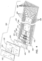
- Strip 400 includes base substrate 402 with four sets of electrodes 404, 406, 408 and 410, and a set of fault detect electrode traces 412 and 413 formed thereon.
- a reagent stripe 414 is coated onto electrode set 404 and micro-electrode set 406 in this embodiment.
- Strip 400 also includes a spacing layer 418 having a void section 420, which, in cooperation with covering layer 422 and base substrate 402, defines the boundaries of the sample receiving chamber. The position of the sample receiving chamber is indicated generally by dashed line 424 on substrate 402.
- the electrode sets and sample sufficiency electrodes are electrically connected to contact pads 426 through traces 428.
- the architecture just described is essentially the same as that described with reference to Fig. 2 , the difference being the electrical devices contained in the measurement zone. Again, a large central portion 430 of the base substrate 402 is not occupied by the electrical pattern and would be available to add additional user interface, power, or digital devices, as described elsewhere herein.
- the first electrode pair 404 encountered by the sample includes working electrode 432, a single-finger electrode.
- First electrode pair 404 also includes counter electrode pair 434, a two-finger electrode, with one finger on either side of working electrode 432.
- Each finger in first electrode pair 434 is about 250 ⁇ m wide, and a gap of about 250 ⁇ m separates each counter electrode finger from the working electrode finger.
- the system driver connects to contacts 426 to use the first electrode pair 404 to obtain an estimated concentration of analyte in the sample.
- the second electrode pair 406 comprises two electrodes of five fingers each. These fingers are each about 50 ⁇ m wide with a separation of about 30 ⁇ m between them. Each electrode in the second pair connects to a conductive trace 428 to be electrically connected to a contact 426, which contacts are used to drive and measure for a first correction factor such as hematocrit based on the analyte interaction with the second pair of electrodes.
- the third electrode pair 408 is also a micro-electrode configuration, with each of the two electrodes in the third pair 408 having five fingers interdigitated with the five in the other electrode. Each finger is again about 50 ⁇ m wide, with a gap of about 30 ⁇ m between them.
- Each electrode in the third pair 408 is connected via a conductive trace 428 to a contact 426, which contacts are used to drive and measure for a second correction factor such as temperature based on the analyte interaction with the second pair of electrodes.
- the fourth set of electrodes comprises sample sufficiency electrodes 410 that signal when the sample has filled the chamber such that electrode sets 404,406 and 408 can then be driven to perform their respective measurement functions.
- the fifth functionality in the measurement zone of strip 400 relates to fault detect traces 412 and 413 for electrode set 404.
- Trace 413 connects to counter electrode 434 and is used to correct variant voltage across the pair, whereas fault detect trace 412 on working electrode 432 compensates for measured current. Additionally, traces 412 and 413 can be used to apply a potential between the primary traces and the fault detect traces to determine whether there are any defects in the primary traces.
- the sample receiving chamber 424 Even with five electrical devices or functionalities provided in the measurement zone, the sample receiving chamber 424 nonetheless has a very small volume, on the order of less than about 500 nl.
- Substrate 502 includes an electrical pattern 504 formed thereon having contact pads 506 and traces 508 leading to the electrode sets disposed in the measurement zone 510.
- Measurement zone 510 includes a sample receiving chamber 512 having three branches or prongs 514, 516 and 518.
- Branch 514 includes electrode sets 520 and 522
- branch 516 includes electrode sets 524 and 526
- branch 518 includes electrode sets 528 and 530.
- a reagent layer 532 covers electrode sets 520 and 522
- a reagent layer 534 covers electrode sets 524 and 526
- a reagent layer 536 covers electrode set 528 and 530.
- a spacing layer (not shown in Fig. 5 ) as described above is formed with voids corresponding to and defining the branched sample receiving chamber, and a covering layer overlies the spacing layer. Vent holes are formed in the covering layer to allow air to escape each of the branches of the sample receiving chamber.
- reagent layers 532, 534 and 536 can be comprised of three different reagents for testing three different analytes, e.g., a lipid panel that tests total cholesterol, HDL cholesterol and triglycerides.
- all three reagents can be identical, in which case three of the same tests can be performed in parallel, such that each branch of the sample receiving chamber effectively receives its own fresh supply of fluid sample.
- a series of electrode sets in a single-branched chamber poses the potential of contamination to the downstream electrode sets.
- a large portion 538 is available in the middle of substrate 502 and could be configured to support additional electrical devices.
- a power generator 238 is positioned centrally on strip 200.
- the power generator 238 may comprise a battery such as a commercially available custom made Power Paper brand energy cell, available from Power Paper, Ltd., Kibbutz, Israel. These cells are preferably printed on a very thin substrate such as paper or thin polymer. By means of basic screen-printing techniques, different layers of conductive inks are printed to form the various components of cell 238, which are then laminated together and in turn laminated to substrate 220.
- battery 238 has a diameter of about 5.3 mm and a thickness of less than about 0.5 mm.
- Battery 238 is mounted to substrate 220 by ordinary adhesives or other suitable means and connects to leads 248 as show, preferably by conductive epoxy. Battery 238 produces 2.7 - 3.1 Volts, a current of 4 - 5 mA and has an "on time" of between 5-90 seconds. These parameters are sufficient for powering one of the inventive OLED circuits described below, a traditional LED, or a small piezoelectric device which produces sound, or any number of similar devices. In view of the teachings herein, which minimize the footprint of even complex electrode patterns, two or more such batteries 238 could be positioned on strip 200 and wired together to increase power production.
- power generators 238 could be substituted for the battery just described. For example, if only a short burst of energy is needed, for example to light a diode or produce a short audible sound, a super capacitor or ultra-cap modified to have a very slim profile could be used as power generator 238.
- strip 200 would be inserted into the instrument (not shown) for strip identification, strip integrity checks, temperature determination, and charging the capacitor or other power storage element. The self-powered strip is then removed from the instrument, placed at the dose site, and returned to the instrument for measurement computation and display.
- the power generator be as thin as possible so as not to significantly increase the thickness of the test strip.
- a digital device 246 is positioned adjacent power generator 238 and is wired thereto by traces 248.
- Device 246 could be a radio frequency identification (“RFID”) tag.
- RFID 246 is preferably less than about 1mm thick, more preferably less than 0.5 mm thick, and has a width of less than about 7 mm.
- device 246 contains digital calibration data concerning the test strip and can communicate such data to an RFID reader (not shown) that is included in the instrument (not shown). Most commercially available RFID's are typically "passive,” i.e., they are powered by the radio signal emanating from the reader that reads them. Thus, if device 246 is an RFID, it need not be wired to a power generator such as power generator 238. RFID technology is known in the art and the details thereof need not be described any further herein.
- digital device 246 could be provided as an on-board integrated circuit with computing power, powered by battery 238 and connected thereto by traces 248.
- Two commercially available examples include Texas Instruments MSP430C11 and Microchip PIC12F675 integrated low power micro-controllers for governing sample acquisition and rudimentary measurements to support dosing the strip without the strip being inserted in the meter.
- device 246 could be provided in the form of a conventional wired storage device such as a Microchip 24AA01 1K bit serial EEPROM, in which event it would include data such as lot code, calibration data and the like.
- strip 200 also includes a digital device 250 which is comprised of a combination of contact pads 252 and conductive links 254 of electrical pattern 222.
- Contact pads 252 and conductive links 254 are shown in phantom because any one (or all) of them may or may not be present in the finished test strip, depending upon the information that is to be encoded onto the test strip.
- Each link or contact pad can be thought of as a binary switch having a value of 0 (if not present) or 1 (if present). Any given configuration of absent/present links and contact pads may include digital information concerning lot code, expiration date, type of analyte the strip is intended to analyze and so forth.
- a photodiode sensor could be mounted on the test strip in the digital device zone or elsewhere to detect an environmental condition such as ambient light.
- the meter could then apply a voltage to the micro-electrode arrays such as micro-electrode arrays 224 so that they illuminate the measurement zone.
- digital device for purposes of this application is somewhat broader than its common usage in the art, in that it includes devices such as a photodiode or similar devices that may be provided in the digital zone.
- the test strip 200 shown in Figs. 1 and 2 includes a user interface zone 204 that includes OLEDs coated onto micro-electrode arrays. Specifically, with reference to Fig. 2 , OLEDs 226 are coated onto micro-electrodes 224 and OLED 236 is coated onto micro-electrode array 234.
- Electrode arrays 224 are wired through traces 223 to contact pads 216.
- a "triggering event" occurs when strip 200 is inserted into a meter (not shown), upon which event the circuitry of the meter recognizes that a strip has been inserted and produces a voltage across electrode sets 224.
- the coatings 226 illuminate. If the strip 200 is being used in conditions of dim lighting, the OLED coating advantageously illuminates the sample receiving chamber 218 so that the user can visually confirm that the fluid sample is contacting the correct part of the strip 200 and that the sample fluid is being drawn into the strip.
- the spacer and covering layers forming test strip 200 are preferably transparent or translucent such that the light emitted from the OLEDs is visible through them.
- OLED 236 can be configured to illuminate (or turn off) upon sufficient sample being received in the sample receiving chamber.
- Sample sufficiency electrodes 230 are wired through traces 223 to contact pads 216 and in turn to the meter (not shown) that reads the strips. Once the meter detects from electrodes 230 that the chamber is filled with the requisite size sample, the meter can apply a voltage across electrode set 234 through the appropriate contact pads 216 and traces 223. OLED 236 will then illuminate, thereby providing the user a positive visual indication that the chamber has been properly filled.
- Fig. 6 shows a base substrate 600 of another test strip embodiment incorporated by the present invention.
- the test strip has a measurement zone 602, two user interface zones 604 and 604', a power generation zone 606, and a meter connection zone 610.
- This embodiment illustrates the point alluded to above, viz., that the locations of various "zones" of a particular test strip embodying the principles of the present invention may overlap, or in the case of the embodiment illustrated in Fig. 6 , may be discontinuous or bifurcated.
- the sample receiving chamber 612 includes three different electrical devices or functionalities: a measurement electrode set 614, a thermistor 616 and a sample sufficiency electrode set 618. Electrode set 614 is connected to traces 620, which terminate in contact pads 622 disposed at meter connection zone 610 of the strip.
- the sample sufficiency electrode set 618 is part of a circuit which includes a micro-electrode array 624 having an OLED 626 coated thereon and a battery 628. Electrical devices 618, 624 and 628 are wired in series by traces 630, 632 and 634. Traces 630 and 634 terminate in the power generation zone 606 with contact pads 636 (shown in phantom) to which the battery 628 is connected.
- the second or bifurcated user interface zone 604' includes a traditional diode 638 wired by traces 620 to contact pads 622.
- sample sufficiency electrode set 618 acts as a switch in the circuit containing electrodes 618, electrode array 624 and battery 628.
- Battery 628 is a Power Paper type battery as described above that produces 2.7 - 3.1 Volts and a current of 4 - 5 mA for about 5-90 seconds.
- the ionic strength thereof should be sufficient to close the circuit.
- numerous coatings that could be applied and dried onto electrode set 618 to ensure sufficient current transfer upon wetting with other fluid samples.
- closing the circuit is a triggering event which results in a voltage being produced across micro-electrode array 624, which in turn causes OLED layer 626 to illuminate. In this manner, the illumination of OLED 626 provides a positive visual verification to the user that the sample chamber has been filled.
- Electrical device 616 is a thermistor that is used to measure the temperature of the sample receiving chamber.
- One thermistor suitable for device 616 is surface mount thermistor available from Vishay Intertechnology, Inc., Lavern, PA, part no. NTHS-0402N01N100KJ.
- Thermistor 618 is driven by electrical circuitry from a meter (not shown) through contacts 622 and traces 620. If the temperature of the sample receiving chamber is not within a desired range for testing, the meter circuitry can apply a voltage to conventional LED 638 through contacts 622 and traces 620 to cause it to illuminate. This signals the user that the temperature of the sample is outside of a preferred range, in which event the user may then possibly repeat the test under better conditions.
- An LED that is suitable for mounting on substrate 600 is available from Stanley Electrical Sales of America, Inc., part no. PY1114CK. This LED is mounted to base substrate 600 preferably by a conductive epoxy.
- user interface zone 604' may include a signal producing device that produces sound, such as a piezoelectric available from U.S. Electronics, Inc., St. Louis MO., part number USE14240ST.
- Base substrate 700 of the test strip includes a measurement zone that includes a sample fluid receiving chamber 702 having disposed at least partially therein a measurement electrode set 704 and sample sufficiency electrode set 706, whose functionality and operation are described above. Suitable spacing and covering layers (not illustrated in Fig. 7 ) cover substrate 700 to form a test strip.
- Substrate 700 includes a numerical display 712 comprised of individual segments 714 that have a shape not unlike that of the segments used for traditional LED or LCD displays.
- the layer or layers of the test strip (not shown) that cover display 712 are translucent or transparent such that display 712 is visible therethrough.
- Segments 714 include an OLED coating like that described above overlying a micro-electrode IDA, as also described above (but not shown in Fig. 7 ). Each segment 714 has two electrodes (not shown) having two traces 708 extending therefrom and leading to respective contact pads 710. Voltages can be applied across selective ones of the contact pads 710 to illuminate display 712 to produce any of the digits 0 to 9, a "5" being shown illuminated in Fig. 7 .
- test strip having a base substrate 700 as shown in Fig. 7 with one digit has a length of about 33-38mm, a width of less than about 15 mm, preferably about 9mm, and a thickness of less than about 1 mm. It should be appreciated that the micro-electrode arrays and OLEDs coating them (to form segments 714 of display 712) do not increase the thickness of the strip.
- the test strip having substrate 700 is inserted into a meter (not shown), a fluid sample is provided to sample receiving chamber 702, and the meter calculates the numerical estimate of analyte concentration.
- the circuitry in the meter drives voltages across selective ones of the contact pads 710 to illuminate a number on display 712 that corresponds to the estimate of analyte concentration. If only one digit were provided in display 712 as shown in Fig. 7 , and the analyte whose concentration is being estimated were glucose from a blood sample, the single digits could be assigned a range.
- a "0" might correspond to a 50-100 mg/dl concentration of glucose, a "1” to 100-150 mg/dl, a 2 to 150-200 mg/dl and so on. If two digits were provided in display 712, then the display could simply show the first two digits of the result. In such case a "10” displayed would mean 100-109 mg/dl, a "21” would mean 210-219 mg/dl, etc.
- the analyte concentration might be displayed by sequentially displaying digits. For example, "126" mg/dL might be displayed as a “1” followed by a "2", followed by a "6", and the sequence terminated with a unique symbol to indicate completion and avoid user confusion. In this manner, a three-digit whole number can be conveyed to the user with a single digit display.
- Fig. 7 embodies an electrochemical test strip, it should be understood that the innovative on-board display could be provided on test strips which employ other measurement techniques, e.g., photometric principles.
- test strips or biosensors as flattened articles offer several advantages, especially in terms of storing and dispensing, as described in the Dispenser application incorporated above, but it is expected that one skilled in the art would apply the teachings herein to other test devices.
- the inventive display as well as other features described above may be employed in test devices other than biosensors, e.g., devices for food testing and other applications. In such other applications, the devices may have, e.g., a cylindrical or other than a traditional thin test strip type body.
- biosensors incorporating the inventive features described herein, while generally comprising a flat and thin shape may have portions thereof that are sized and shaped to accommodate various electrical devices, as described above.
- Polymer light-emitting devices are typically configured as a thin film (e.g., about 0.1 microns of a polymer such as polyparaphenylene vinylene) sandwiched between two different metallic electrodes.
- the anode is transparent and lies on a transparent substrate.
- the typical combination is indium tin oxide on glass.
- IDA micro-electrode interdigitated array
- the IDAs had 750 pairs of interdigitated fingers with each finger having a width of 2 ⁇ m, a length of 6mm, and a spacing between the next closest finger (i.e., gap width) of about 2 ⁇ m.
- the IDAs were custom fabricated on a silicon wafer by Premitec Inc., Raleigh, N.C.
- the IDAs were each coated with 20 ⁇ l of the solution just described.
- the coated IDAs were then placed in a desiccator and allowed to dry.
- the reagent coatings did not dry uniformly and had a ridge around the circumference of the coating.
- Example II In order to obtain a better coating than that obtained in Example I, a solution of 1% PVP 25k (BASF) was prepared in deionized water. The ruthenium compound used in Example I was then mixed with the PVP solution in a 1:1 ratio and the resulting solution was applied to several additional IDAs.
- the first IDA had a spacing between the interdigitated fingers of approximately 2 ⁇ m as described above and the other had a finger spacing of approximately 21 ⁇ m and 50 finger pairs.
- This second IDA had a finger width of 21 ⁇ m, a finger length of 6 mm and was formed on a Upilex substrate also custom fabricated by Premitec.
- the coating composition containing the PVP produced a uniform coating on both types of IDA's.
- the electrodes used in the preceding examples were left at room temperature and humidity and the experiments described above repeated at approximately 1 - 2 month intervals.
- the OLEDs still illuminated with the same voltages used in the previous examples.
Landscapes
- Life Sciences & Earth Sciences (AREA)
- Health & Medical Sciences (AREA)
- Chemical & Material Sciences (AREA)
- Engineering & Computer Science (AREA)
- Organic Chemistry (AREA)
- Biochemistry (AREA)
- Physics & Mathematics (AREA)
- General Health & Medical Sciences (AREA)
- Analytical Chemistry (AREA)
- Molecular Biology (AREA)
- Immunology (AREA)
- Wood Science & Technology (AREA)
- Zoology (AREA)
- Bioinformatics & Cheminformatics (AREA)
- Biophysics (AREA)
- General Physics & Mathematics (AREA)
- Biomedical Technology (AREA)
- Pathology (AREA)
- Proteomics, Peptides & Aminoacids (AREA)
- Biotechnology (AREA)
- Hematology (AREA)
- Microbiology (AREA)
- Genetics & Genomics (AREA)
- General Engineering & Computer Science (AREA)
- Medicinal Chemistry (AREA)
- Chemical Kinetics & Catalysis (AREA)
- Electrochemistry (AREA)
- Urology & Nephrology (AREA)
- Food Science & Technology (AREA)
- Sustainable Development (AREA)
- Investigating Or Analysing Biological Materials (AREA)
- Investigating Or Analyzing Materials By The Use Of Electric Means (AREA)
Applications Claiming Priority (2)
| Application Number | Priority Date | Filing Date | Title |
|---|---|---|---|
| US48024303P | 2003-06-20 | 2003-06-20 | |
| PCT/US2004/019652 WO2005012900A1 (en) | 2003-06-20 | 2004-06-18 | Biosensor with multiple electrical functionalities |
Publications (2)
| Publication Number | Publication Date |
|---|---|
| EP1642125A1 EP1642125A1 (en) | 2006-04-05 |
| EP1642125B1 true EP1642125B1 (en) | 2017-09-27 |
Family
ID=33539277
Family Applications (3)
| Application Number | Title | Priority Date | Filing Date |
|---|---|---|---|
| EP04776796.7A Not-in-force EP1642125B1 (en) | 2003-06-20 | 2004-06-18 | Biosensor with multiple electrical functionalities |
| EP17204072.7A Pending EP3376223A1 (en) | 2003-06-20 | 2004-06-18 | Devices relating to electrochemical biosensors |
| EP04776780.1A Active EP1642124B1 (en) | 2003-06-20 | 2004-06-18 | Electrochemical biosensors |
Family Applications After (2)
| Application Number | Title | Priority Date | Filing Date |
|---|---|---|---|
| EP17204072.7A Pending EP3376223A1 (en) | 2003-06-20 | 2004-06-18 | Devices relating to electrochemical biosensors |
| EP04776780.1A Active EP1642124B1 (en) | 2003-06-20 | 2004-06-18 | Electrochemical biosensors |
Country Status (13)
| Country | Link |
|---|---|
| US (3) | US8506775B2 (es) |
| EP (3) | EP1642125B1 (es) |
| JP (2) | JP4624999B2 (es) |
| KR (2) | KR100845163B1 (es) |
| CN (1) | CN1839313B (es) |
| AU (1) | AU2004250223B2 (es) |
| BR (1) | BRPI0411695A (es) |
| CA (2) | CA2529579C (es) |
| ES (1) | ES2657627T3 (es) |
| HK (1) | HK1096151A1 (es) |
| MX (1) | MXPA05013747A (es) |
| PL (1) | PL1642124T3 (es) |
| WO (2) | WO2005012900A1 (es) |
Families Citing this family (176)
| Publication number | Priority date | Publication date | Assignee | Title |
|---|---|---|---|---|
| US8460243B2 (en) * | 2003-06-10 | 2013-06-11 | Abbott Diabetes Care Inc. | Glucose measuring module and insulin pump combination |
| US7722536B2 (en) | 2003-07-15 | 2010-05-25 | Abbott Diabetes Care Inc. | Glucose measuring device integrated into a holster for a personal area network device |
| US7920906B2 (en) | 2005-03-10 | 2011-04-05 | Dexcom, Inc. | System and methods for processing analyte sensor data for sensor calibration |
| EP3273232A2 (en) * | 2003-12-04 | 2018-01-24 | Panasonic Healthcare Holdings Co., Ltd. | Method of measuring blood component, sensor used in the method, and measuring device |
| EP3285068B1 (en) * | 2003-12-04 | 2020-02-12 | PHC Holdings Corporation | Method of electrochemically measuring hematocrit (hct) |
| US9012232B2 (en) * | 2005-07-15 | 2015-04-21 | Nipro Diagnostics, Inc. | Diagnostic strip coding system and related methods of use |
| US7501301B2 (en) * | 2004-03-10 | 2009-03-10 | The Board Of Trustees Of The Leland Stanford Junior University | Low cost fabrication of microelectrode arrays for cell-based biosensors and drug discovery methods |
| CA2559297C (en) * | 2004-04-19 | 2012-05-22 | Matsushita Electric Industrial Co., Ltd. | Method for measuring blood components and biosensor and measuring instrument for use therein |
| CA2572455C (en) | 2004-06-04 | 2014-10-28 | Therasense, Inc. | Diabetes care host-client architecture and data management system |
| US7582262B2 (en) * | 2004-06-18 | 2009-09-01 | Roche Diagnostics Operations, Inc. | Dispenser for flattened articles |
| US7556723B2 (en) * | 2004-06-18 | 2009-07-07 | Roche Diagnostics Operations, Inc. | Electrode design for biosensor |
| US20060020192A1 (en) | 2004-07-13 | 2006-01-26 | Dexcom, Inc. | Transcutaneous analyte sensor |
| CN101091114A (zh) * | 2004-08-31 | 2007-12-19 | 生命扫描苏格兰有限公司 | 制造自动校准传感器的方法 |
| US7418285B2 (en) * | 2004-12-29 | 2008-08-26 | Abbott Laboratories | Analyte test sensor and method of manufacturing the same |
| US9351669B2 (en) | 2009-09-30 | 2016-05-31 | Abbott Diabetes Care Inc. | Interconnect for on-body analyte monitoring device |
| US7545272B2 (en) | 2005-02-08 | 2009-06-09 | Therasense, Inc. | RF tag on test strips, test strip vials and boxes |
| US20070103678A1 (en) * | 2005-02-14 | 2007-05-10 | Sterling Bernhard B | Analyte detection system with interferent identification and correction |
| JP4631027B2 (ja) * | 2005-03-29 | 2011-02-16 | 独立行政法人産業技術総合研究所 | Icタグ搭載型バイオセンサーおよびその包装体 |
| US7818132B2 (en) * | 2005-06-10 | 2010-10-19 | Arkray Factory Ltd. | Test system |
| CN101198867B (zh) * | 2005-06-14 | 2013-01-02 | 霍夫曼-拉罗奇有限公司 | 用于控制短路故障对共平面的电化学传感器影响的方法和设备 |
| US7955856B2 (en) * | 2005-07-15 | 2011-06-07 | Nipro Diagnostics, Inc. | Method of making a diagnostic test strip having a coding system |
| US8999125B2 (en) | 2005-07-15 | 2015-04-07 | Nipro Diagnostics, Inc. | Embedded strip lot autocalibration |
| GB0514728D0 (en) | 2005-07-19 | 2005-08-24 | Hypoguard Ltd | Biosensor and method of manufacture |
| US20070017824A1 (en) * | 2005-07-19 | 2007-01-25 | Rippeth John J | Biosensor and method of manufacture |
| GB0518527D0 (en) * | 2005-09-10 | 2005-10-19 | Oxford Biosensors Ltd | Scaling factor for an output of an electrochemical cell |
| KR100680267B1 (ko) * | 2005-09-16 | 2007-02-08 | 주식회사 인포피아 | 식별정보를 포함하는 바이오 센서 및 바이오 센서의식별정보 판독장치 |
| UY29918A1 (es) * | 2005-11-14 | 2007-06-29 | Bayer Healthcare Llc | Reactivo para sensores de prueba que contiene polimeros de celulosa |
| WO2007057473A1 (de) * | 2005-11-21 | 2007-05-24 | Kurt Hoffmann | Verfahren zur detektion von abbauprozessen |
| US7741142B2 (en) * | 2005-11-22 | 2010-06-22 | Hewlett-Packard Development Company, L.P. | Method of fabricating a biosensor |
| EP1793228A1 (de) * | 2005-12-05 | 2007-06-06 | F. Hoffmann-La Roche AG | Verfahren zum akustischen Ausgeben einer Information in einem Analysesystem |
| TWI335428B (en) * | 2005-12-23 | 2011-01-01 | Apex Biotechnology Corp | Electrochemical test strip |
| JP4735833B2 (ja) * | 2006-01-13 | 2011-07-27 | セイコーエプソン株式会社 | バイオチップ及びバイオセンサ |
| EP1813937A1 (de) * | 2006-01-25 | 2007-08-01 | Roche Diagnostics GmbH | Elektrochemisches Biosensor-Analysesystem |
| US11559810B2 (en) | 2006-03-13 | 2023-01-24 | Trividia Health, Inc. | Method and apparatus for coding diagnostic meters |
| US8388906B2 (en) * | 2006-03-13 | 2013-03-05 | Nipro Diagnostics, Inc. | Apparatus for dispensing test strips |
| US8388905B2 (en) * | 2006-03-13 | 2013-03-05 | Nipro Diagnostics, Inc. | Method and apparatus for coding diagnostic meters |
| US8940246B2 (en) | 2006-03-13 | 2015-01-27 | Nipro Diagnostics, Inc. | Method and apparatus for coding diagnostic meters |
| US7887682B2 (en) | 2006-03-29 | 2011-02-15 | Abbott Diabetes Care Inc. | Analyte sensors and methods of use |
| JP5027455B2 (ja) * | 2006-06-29 | 2012-09-19 | ユニ・チャーム株式会社 | 排泄物検知センサ |
| US20080020452A1 (en) * | 2006-07-18 | 2008-01-24 | Natasha Popovich | Diagnostic strip coding system with conductive layers |
| JP5239860B2 (ja) * | 2006-07-26 | 2013-07-17 | パナソニック株式会社 | バイオセンサ測定システム、および測定方法 |
| US20080083618A1 (en) * | 2006-09-05 | 2008-04-10 | Neel Gary T | System and Methods for Determining an Analyte Concentration Incorporating a Hematocrit Correction |
| TWI317015B (en) * | 2006-10-02 | 2009-11-11 | Eps Bio Technology Corp | Biosensing device |
| US9046480B2 (en) | 2006-10-05 | 2015-06-02 | Lifescan Scotland Limited | Method for determining hematocrit corrected analyte concentrations |
| EP2082222B1 (en) | 2006-10-05 | 2012-11-21 | Lifescan Scotland Limited | Systems and methods for determining a substantially hematocrit independent analyte concentration |
| US20080101986A1 (en) * | 2006-10-31 | 2008-05-01 | Selwayan Saini | Analytical test strip with electroluminescent module |
| US20080101984A1 (en) * | 2006-10-31 | 2008-05-01 | Selwayan Saini | Method for determining an analyte in a bodily fluid sample |
| US20080101987A1 (en) * | 2006-10-31 | 2008-05-01 | Selwayan Saini | Analytical test strip with electroluminescent lamp |
| US7740801B2 (en) * | 2006-10-31 | 2010-06-22 | Lifescan Scotland Limited | System for determination of an analyte in a bodily fluid sample that includes an electroluminescent component |
| CA2608609A1 (en) * | 2006-10-31 | 2008-04-30 | Lefescan Scotland Limited | Analytical test strip with electroluminescent lamp |
| US20080100689A1 (en) * | 2006-10-31 | 2008-05-01 | Selwayan Saini | Method for manufacturing an analytical test strip with an electroluminescent component |
| WO2008076212A1 (en) * | 2006-12-13 | 2008-06-26 | Bayer Healthcare Llc | Biosensor with coded information and method for manufacturing the same |
| US8409424B2 (en) * | 2006-12-19 | 2013-04-02 | Apex Biotechnology Corp. | Electrochemical test strip, electrochemical test system, and measurement method using the same |
| TW200829918A (en) * | 2007-01-03 | 2008-07-16 | Hmd Biomedical Inc | Identification notation-containing test strip and test instrument thereof |
| WO2008119039A2 (en) * | 2007-03-27 | 2008-10-02 | Paul Wessel | Test strip and monitoring device |
| US8460524B2 (en) * | 2007-04-18 | 2013-06-11 | Nipro Diagnostics, Inc. | System and methods of chemistry patterning for a multiple well biosensor |
| US8597190B2 (en) | 2007-05-18 | 2013-12-03 | Optiscan Biomedical Corporation | Monitoring systems and methods with fast initialization |
| GB0711780D0 (en) * | 2007-06-18 | 2007-07-25 | Oxford Biosensors Ltd | Electrochemical data rejection methodology |
| US8206564B2 (en) * | 2007-07-23 | 2012-06-26 | Bayer Healthcare Llc | Biosensor calibration system |
| CN101784894A (zh) * | 2007-08-06 | 2010-07-21 | 拜尔健康护理有限责任公司 | 自动校准的系统和方法 |
| WO2009032760A2 (en) | 2007-08-30 | 2009-03-12 | Pepex Biomedical Llc | Electrochmical sensor and method for manufacturing |
| WO2009051901A2 (en) | 2007-08-30 | 2009-04-23 | Pepex Biomedical, Llc | Electrochemical sensor and method for manufacturing |
| DE102007041395A1 (de) * | 2007-08-31 | 2009-03-05 | Thüringisches Institut für Textil- und Kunststoff-Forschung e.V. | UV-Dosimeter mit Eigenspeisung und Warnsignal (Anzeige) |
| US7943022B2 (en) * | 2007-09-04 | 2011-05-17 | Lifescan, Inc. | Analyte test strip with improved reagent deposition |
| TW200914826A (en) * | 2007-09-21 | 2009-04-01 | Apex Biotechnology Corp | Electrochemical quantitative analysis system and method for the same |
| EP2040072B1 (de) * | 2007-09-22 | 2013-01-02 | Roche Diagnostics GmbH | Analysesystem zur Bestimmung der Konzentration eines Analyten in einer Körperflüssigkeit |
| CN101849180B (zh) * | 2007-09-24 | 2017-08-18 | 安晟信医疗科技控股公司 | 多区域分析物测试传感器 |
| PL2205757T3 (pl) * | 2007-10-31 | 2017-10-31 | Hoffmann La Roche | Elektryczne obwody drukowane dla biosensora i sposób wytwarzania biosensora |
| US8241488B2 (en) | 2007-11-06 | 2012-08-14 | Bayer Healthcare Llc | Auto-calibrating test sensors |
| US7809512B2 (en) * | 2007-11-11 | 2010-10-05 | Bayer Healthcare Llc | Biosensor coding system |
| WO2009076263A1 (en) | 2007-12-10 | 2009-06-18 | Bayer Healthcare Llc | An auto-calibrating test sensor and method of making the same |
| JP4944083B2 (ja) | 2007-12-12 | 2012-05-30 | パナソニック株式会社 | 生体試料測定用試験片および生体試料測定装置 |
| US20090205399A1 (en) * | 2008-02-15 | 2009-08-20 | Bayer Healthcare, Llc | Auto-calibrating test sensors |
| US20090223287A1 (en) * | 2008-03-04 | 2009-09-10 | Visgeneer, Inc. | Bio-Monitoring System and Methods of Use Thereof |
| JP2009250806A (ja) | 2008-04-07 | 2009-10-29 | Panasonic Corp | バイオセンサシステム、センサチップおよび血液試料中の分析物濃度の測定方法 |
| US8032321B2 (en) * | 2008-07-15 | 2011-10-04 | Bayer Healthcare Llc | Multi-layered biosensor encoding systems |
| US8465977B2 (en) | 2008-07-22 | 2013-06-18 | Roche Diagnostics Operations, Inc. | Method and apparatus for lighted test strip |
| DE102008038457B4 (de) * | 2008-08-20 | 2013-10-24 | Advanced Display Technology Ag | Vorrichtung zur fluidischen Anzeige |
| EP2335067A1 (en) * | 2008-09-30 | 2011-06-22 | Menai Medical Technologies Limited | Sample measurement system |
| US8424763B2 (en) * | 2008-10-07 | 2013-04-23 | Bayer Healthcare Llc | Method of forming an auto-calibration circuit or label |
| KR101003077B1 (ko) * | 2008-10-16 | 2010-12-21 | 세종공업 주식회사 | 전기화학적 바이오센서의 구조 및 바이오센서를 이용한 측정방법 |
| TW201018903A (en) * | 2008-11-07 | 2010-05-16 | Yuan-Soon Ho | Inspection device and inspection method used for measuring substance concentration inside stomach |
| US8721851B2 (en) * | 2008-11-28 | 2014-05-13 | Panasonic Healthcare Co., Ltd. | Sensor chip, biosensor system, method for measuring temperature of biological sample, method for measuring temperature of blood sample, and method for measuring concentration of analyte in blood sample |
| KR101047363B1 (ko) | 2008-12-22 | 2011-07-07 | 한국전자통신연구원 | 자가 발전이 가능한 다중 기능 센서 및 이의 제조 방법 |
| JP4876186B2 (ja) | 2009-01-30 | 2012-02-15 | パナソニック株式会社 | 生体試料の温度測定方法、生体試料の濃度測定方法、センサチップおよびバイオセンサシステム |
| WO2010104993A2 (en) | 2009-03-10 | 2010-09-16 | The Regents Of The University Of California | Fluidic flow cytometry devices and particle sensing based on signal-encoding |
| US9237864B2 (en) | 2009-07-02 | 2016-01-19 | Dexcom, Inc. | Analyte sensors and methods of manufacturing same |
| KR101420773B1 (ko) * | 2009-07-15 | 2014-07-17 | 주성엔지니어링(주) | 전기광학소자 및 이의 제작 방법 |
| US20110048972A1 (en) * | 2009-08-31 | 2011-03-03 | Lifescan Scotland Limited | Multi-analyte test strip with shared counter/reference electrode and inline electrode configuration |
| CN101670998B (zh) * | 2009-09-16 | 2011-10-26 | 哈尔滨工业大学 | 点面电极系统及利用该系统进行微流体驱动的方法 |
| KR100980316B1 (ko) * | 2009-12-09 | 2010-09-06 | 동진메디칼 주식회사 | 온도보상 기능을 구비한 스트립 및 이를 이용한 혈당측정방법 |
| TWI440853B (zh) * | 2009-12-14 | 2014-06-11 | Taidoc Technology Corp | 具有校正血容比功能之分析物測量電化學生物感測試紙、生物感測器裝置、系統以及測量方法 |
| CA2788556A1 (en) * | 2010-01-25 | 2011-07-28 | Albert Einstein College Of Medicine Of Yeshiva University | Device for collecting and analyzing migratory tumor cells |
| US8529742B2 (en) * | 2010-02-24 | 2013-09-10 | Matthew K. Musho | Electrochemical sensor with controlled variation of working electrode |
| GB201005357D0 (en) | 2010-03-30 | 2010-05-12 | Menai Medical Technologies Ltd | Sampling plate |
| GB201005359D0 (en) | 2010-03-30 | 2010-05-12 | Menai Medical Technologies Ltd | Sampling plate |
| US8940141B2 (en) | 2010-05-19 | 2015-01-27 | Lifescan Scotland Limited | Analytical test strip with an electrode having electrochemically active and inert areas of a predetermined size and distribution |
| EP3156796A1 (en) | 2010-06-09 | 2017-04-19 | Optiscan Biomedical Corporation | Measuring analytes in a fluid sample drawn from a patient |
| WO2012028697A1 (en) | 2010-09-01 | 2012-03-08 | Eth Zürich, Institute Of Molecular Biology And Biophysics | Affinity purification system based on donor strand complementation |
| KR20140022755A (ko) * | 2010-09-09 | 2014-02-25 | 에스.이.에이. 메디컬 시스템즈, 인코포레이티드 | 이미턴스 스펙트로스코피를 사용하여 정맥 약물을 관리하기 위한 시스템들 및 방법들 |
| US8431408B2 (en) | 2010-10-15 | 2013-04-30 | Roche Diagnostics Operations, Inc. | Handheld diabetes managing device with light pipe for enhanced illumination |
| KR101885936B1 (ko) * | 2010-10-21 | 2018-09-10 | 더 리젠츠 오브 더 유니버시티 오브 캘리포니아 | 무선 전력이 공급되는 전자 회로를 포함하는 미세 유체 |
| US20130253294A1 (en) * | 2010-12-17 | 2013-09-26 | Sanofi-Aventis Deutschland Gmbh | Bodily fluid analysis device |
| WO2012106972A1 (en) * | 2011-02-08 | 2012-08-16 | Beijing Metis Biomed Ltd | Blood glucose sensor |
| US10136845B2 (en) | 2011-02-28 | 2018-11-27 | Abbott Diabetes Care Inc. | Devices, systems, and methods associated with analyte monitoring devices and devices incorporating the same |
| GB2489504A (en) | 2011-03-31 | 2012-10-03 | Sapient Sensors | A device for identifying the presence of a specific target molecule or biomarker by sensing an electrical property |
| JP6133320B2 (ja) * | 2011-11-22 | 2017-05-24 | シーメンス・ヘルスケア・ダイアグノスティックス・インコーポレーテッドSiemens Healthcare Diagnostics Inc. | 互いに嵌合されたアレイおよびその製造方法 |
| KR101466222B1 (ko) * | 2012-06-01 | 2014-12-01 | 주식회사 아이센스 | 정확도가 향상된 전기화학적 바이오센서 |
| US8877023B2 (en) | 2012-06-21 | 2014-11-04 | Lifescan Scotland Limited | Electrochemical-based analytical test strip with intersecting sample-receiving chambers |
| US9128038B2 (en) | 2012-06-21 | 2015-09-08 | Lifescan Scotland Limited | Analytical test strip with capillary sample-receiving chambers separated by a physical barrier island |
| WO2014057625A1 (ja) * | 2012-10-10 | 2014-04-17 | パナソニックヘルスケア株式会社 | 生体情報測定装置 |
| CN105008895B (zh) | 2012-10-15 | 2019-02-15 | 纳诺赛莱克特生物医药股份有限公司 | 颗粒分选的系统、设备和方法 |
| BR112015012958B1 (pt) | 2012-12-03 | 2022-03-15 | Pepex Biomedical, Inc | Módulo sensor para detectar um analito em uma amostra de sangue |
| TWI493186B (zh) * | 2013-02-08 | 2015-07-21 | Hmd Biomedical Inc | 檢測試片、檢測裝置及檢測方法 |
| TWI477772B (zh) | 2013-02-25 | 2015-03-21 | Apex Biotechnology Corp | 電極試片及感測試片及其系統 |
| CN104034780B (zh) * | 2013-03-06 | 2016-07-06 | 五鼎生物技术股份有限公司 | 电极试片及感测试片及具有校正血容比的感测系统 |
| US9157883B2 (en) * | 2013-03-07 | 2015-10-13 | Lifescan Scotland Limited | Methods and systems to determine fill direction and fill error in analyte measurements |
| US9445445B2 (en) | 2013-03-14 | 2016-09-13 | Dexcom, Inc. | Systems and methods for processing and transmitting sensor data |
| EP3385706A1 (en) | 2013-03-15 | 2018-10-10 | Roche Diabetes Care GmbH | Methods of scaling data used to construct biosensor algorithms as well as devices, apparatuses and systems incorporating the same |
| WO2014140172A1 (en) | 2013-03-15 | 2014-09-18 | Roche Diagnostics Gmbh | Methods of failsafing electrochemical measurements of an analyte as well as devices, apparatuses and systems incorporating the same |
| KR101743382B1 (ko) | 2013-03-15 | 2017-06-02 | 에프. 호프만-라 로슈 아게 | 전기화학적 측정 중 높은 항산화제 레벨들을 검출하고 그로부터 분석물질 농도를 페일세이프하는 방법들 뿐만 아니라 상기 방법들을 통합한 기기들, 장치들 및 시스템들 |
| CN105247356B (zh) | 2013-03-15 | 2017-11-07 | 豪夫迈·罗氏有限公司 | 使用来自电化学分析物测量中的恢复脉冲的信息的方法以及合并所述方法的设备、装置和系统 |
| EP2781919A1 (en) | 2013-03-19 | 2014-09-24 | Roche Diagniostics GmbH | Method / device for generating a corrected value of an analyte concentration in a sample of a body fluid |
| WO2014180939A1 (en) | 2013-05-08 | 2014-11-13 | Roche Diagnostics Gmbh | Stabilization of enzymes by nicotinic acid |
| CN105308438A (zh) | 2013-06-10 | 2016-02-03 | 豪夫迈·罗氏有限公司 | 用于检测体液中分析物的方法和系统 |
| US9529503B2 (en) * | 2013-06-27 | 2016-12-27 | Lifescan Scotland Limited | Analyte-measurement system recording user menu choices |
| CN104330444A (zh) * | 2013-07-22 | 2015-02-04 | 财团法人多次元智能It融合系统研究团 | 具有近距离无线通信基础的电气化学性生物传感器及利用其测定成分的方法 |
| CN105492888B (zh) * | 2013-09-05 | 2018-08-10 | 英派尔科技开发有限公司 | 利用oled阵列的细胞培养和跟踪 |
| US9383332B2 (en) * | 2013-09-24 | 2016-07-05 | Lifescan Scotland Limited | Analytical test strip with integrated battery |
| US9571904B2 (en) * | 2013-11-21 | 2017-02-14 | Ge Healthcare Bio-Sciences Ab | Systems and methods for status indication in a single-use biomedical and bioprocess system |
| EP3074524B1 (en) | 2013-11-27 | 2019-11-06 | Roche Diabetes Care GmbH | Composition comprising up-converting phosphors for detecting an analyte |
| GB201321430D0 (en) * | 2013-12-04 | 2014-01-15 | Spd Swiss Prec Diagnostics Gmbh | Assay device |
| KR101552912B1 (ko) * | 2013-12-24 | 2015-09-15 | (주) 파루 | 순환 전압전류법을 이용한 측정 태그 및 그 제조 방법 |
| KR101552777B1 (ko) * | 2013-12-31 | 2015-09-14 | 재단법인 다차원 스마트 아이티 융합시스템 연구단 | 바이오센서 패키지 및 그 제조 방법 |
| KR101559215B1 (ko) * | 2013-12-31 | 2015-10-15 | 재단법인 다차원 스마트 아이티 융합시스템 연구단 | 바이오센서 패키지 및 그 제조 방법 |
| KR101585313B1 (ko) * | 2014-01-06 | 2016-01-13 | 재단법인 다차원 스마트 아이티 융합시스템 연구단 | 정전 용량을 이용한 바이오센서 및 시료 유입 감지 방법 |
| US9897566B2 (en) | 2014-01-13 | 2018-02-20 | Changsha Sinocare Inc. | Disposable test sensor |
| US10114008B2 (en) | 2014-01-21 | 2018-10-30 | Empire Technology Development Llc | Methods and devices for high throughput screening of conditions affecting stem cell differentiation |
| US9939401B2 (en) | 2014-02-20 | 2018-04-10 | Changsha Sinocare Inc. | Test sensor with multiple sampling routes |
| EP2927319A1 (en) | 2014-03-31 | 2015-10-07 | Roche Diagnostics GmbH | High load enzyme immobilization by crosslinking |
| CA2945612C (en) | 2014-04-14 | 2019-09-10 | F. Hoffmann-La Roche Ag | Phenazinium mediators |
| US9370401B2 (en) * | 2014-05-12 | 2016-06-21 | Philip W. Sayles | Millimeter-sized recognition signal badge and identification system for accurately discerning and sorting among similar kinds, shapes, and sizes of surgical instruments |
| US10036709B2 (en) * | 2014-05-20 | 2018-07-31 | Roche Diabetes Care, Inc. | BG meter illuminated test strip |
| BR112016028536B1 (pt) | 2014-06-04 | 2021-11-30 | Pepex Biomedical, Inc | Sensor compreendendo um membro de perfuração de pele e uma zona de análise de amostra de sangue |
| JP6588927B2 (ja) * | 2014-06-05 | 2019-10-09 | エフ ホフマン−ラ ロッシュ アクチェン ゲゼルシャフト | テストエレメントの完全性のための電極装置 |
| KR102247666B1 (ko) * | 2014-08-22 | 2021-05-03 | 삼성전자주식회사 | 전기화학식 바이오센서 |
| US10060907B2 (en) | 2014-08-22 | 2018-08-28 | Roche Diagnostic Operations, Inc. | Redoxindicators |
| CN113444764B (zh) | 2014-08-25 | 2024-04-19 | 豪夫迈·罗氏有限公司 | 对两个电极测试条进行干扰补偿 |
| CA2960984A1 (en) * | 2014-09-12 | 2016-03-17 | Nipro Diagnostics, Inc. | Apparatus for diagnostic meter strip control and identification |
| WO2016073395A1 (en) * | 2014-11-03 | 2016-05-12 | Roche Diabetes Care, Inc. | Electrode arrangements for electrochemical test elements and methods of use thereof |
| JP6410308B2 (ja) * | 2014-12-12 | 2018-10-24 | 国立大学法人東北大学 | センサチップ、検出システム、及び、検出方法 |
| CN107250792A (zh) * | 2014-12-31 | 2017-10-13 | 三伟达保健公司 | 具有干扰校正的葡萄糖测试条 |
| CN104730135A (zh) * | 2015-04-07 | 2015-06-24 | 天津理工大学 | 基于纳米复合材料修饰丝网印刷电极的非酶葡萄糖传感器 |
| FR3035220A1 (fr) * | 2015-04-20 | 2016-10-21 | Commissariat Energie Atomique | " dispositif electronique de mesure d'au moins une caracteristique electrique d'un objet " |
| EP3088880B1 (en) * | 2015-04-28 | 2024-04-24 | Industrial Technology Research Institute | Methods for measuring analyte concentration |
| JP6607437B2 (ja) * | 2015-06-26 | 2019-11-20 | 国立研究開発法人産業技術総合研究所 | バイオセンサ |
| EP3390654A4 (en) * | 2015-12-17 | 2019-07-24 | Polymer Technology Systems, Inc. | SYSTEMS AND METHODS FOR A MULTIPURPOSE ELECTROCHEMICAL TEST STRIP WHICH MAY COMPRISE ONE OR MORE TESTS FOR DIFFERENT ANALYTES IN THE SAME TEST STRIPLET |
| EP3391036A4 (en) * | 2015-12-18 | 2019-07-31 | Trividia Health, Inc. | IN VITRO SENSOR USING A TRIPOLAR IMPEDANCE MEASUREMENT |
| EP3454056A4 (en) * | 2016-02-25 | 2019-06-26 | PHC Holdings Corporation | BIOSENSOR |
| CA3133253A1 (en) | 2016-03-31 | 2017-10-05 | Dexcom, Inc. | Systems and methods for display device and sensor electronics unit communication |
| CA3035874A1 (en) | 2016-10-05 | 2018-04-12 | F. Hoffmann-La Roche Ag | Detection reagents and electrode arrangements for multi-analyte diagnostic test elements, as well as methods of using the same |
| GB2555855A (en) * | 2016-11-14 | 2018-05-16 | Sumitomo Chemical Co | Short-range radio frequency communication device |
| WO2018097214A1 (ja) | 2016-11-25 | 2018-05-31 | パナソニックヘルスケアホールディングス株式会社 | 生体試料の成分を測定する方法 |
| US11371957B2 (en) * | 2017-06-30 | 2022-06-28 | Abbott Diabetes Care Inc. | Method and apparatus for analyte detection using an electrochemical biosensor |
| EP3669179B1 (en) * | 2017-08-17 | 2023-07-19 | Abbott Point Of Care Inc | Systems for performing optical and electrochemical assays |
| US11060994B2 (en) * | 2017-08-17 | 2021-07-13 | Abbott Point Of Care Inc. | Techniques for performing optical and electrochemical assays with universal circuitry |
| EP3669178B1 (en) | 2017-08-17 | 2023-07-19 | Abbott Point Of Care Inc | Systems for performing optical and electrochemical assays |
| US20200278313A1 (en) * | 2017-11-17 | 2020-09-03 | Siemens Healthcare Diagnostics Inc. | Sensor assembly and method of using same |
| JP7252967B2 (ja) | 2018-02-28 | 2023-04-05 | エフ. ホフマン-ラ ロシュ アーゲー | 連続検体測定のための生体適合性コーティング |
| CN110412099B (zh) * | 2018-04-30 | 2022-05-13 | 财团法人工业技术研究院 | 生物传感器和生物检测方法 |
| CN111202506A (zh) * | 2018-11-21 | 2020-05-29 | 浙江清华柔性电子技术研究院 | 流体的检测器件及其制备方法、血管中血液的检测器件 |
| CN109752423B (zh) * | 2019-01-21 | 2022-03-11 | 上海交通大学 | 一种基于有机薄膜晶体管阵列的尿酸传感器及控制方法 |
| CN111189883A (zh) * | 2020-01-17 | 2020-05-22 | 杭州瑞盟科技有限公司 | 一种血糖检测系统及方法 |
| CN111239229B (zh) * | 2020-02-24 | 2023-04-11 | 江苏鱼跃医疗设备股份有限公司 | 一种双通道电化学生物传感器及测量血红素浓度的方法 |
| US20210277439A1 (en) * | 2020-03-04 | 2021-09-09 | Yu-Chung Norman Cheng | Malaria detection method and device |
| US20220057358A1 (en) * | 2020-08-20 | 2022-02-24 | Polymer Technology Systems, Inc. | Systems and Methods for a Test Strip Calibrator Simulating an Electrochemical Test Strip |
Family Cites Families (84)
| Publication number | Priority date | Publication date | Assignee | Title |
|---|---|---|---|---|
| DE3228542A1 (de) | 1982-07-30 | 1984-02-02 | Siemens AG, 1000 Berlin und 8000 München | Verfahren zur bestimmung der konzentration elektrochemisch umsetzbarer stoffe |
| US4713165A (en) * | 1986-07-02 | 1987-12-15 | Ilex Corporation | Sensor having ion-selective electrodes |
| WO1989009397A1 (en) * | 1988-03-31 | 1989-10-05 | Matsushita Electric Industrial Co., Ltd. | Biosensor and process for its production |
| US5312762A (en) * | 1989-03-13 | 1994-05-17 | Guiseppi Elie Anthony | Method of measuring an analyte by measuring electrical resistance of a polymer film reacting with the analyte |
| JPH02310457A (ja) * | 1989-05-26 | 1990-12-26 | Matsushita Electric Ind Co Ltd | バイオセンサ |
| JPH0820412B2 (ja) * | 1990-07-20 | 1996-03-04 | 松下電器産業株式会社 | 使い捨てセンサを用いた定量分析方法、及び装置 |
| JPH0526838A (ja) * | 1991-07-23 | 1993-02-02 | Aloka Co Ltd | 微小白金電極 |
| US5264103A (en) * | 1991-10-18 | 1993-11-23 | Matsushita Electric Industrial Co., Ltd. | Biosensor and a method for measuring a concentration of a substrate in a sample |
| JP2658769B2 (ja) * | 1991-10-21 | 1997-09-30 | 松下電器産業株式会社 | バイオセンサ |
| JP2541081B2 (ja) * | 1992-08-28 | 1996-10-09 | 日本電気株式会社 | バイオセンサ及びバイオセンサの製造・使用方法 |
| US5385846A (en) | 1993-06-03 | 1995-01-31 | Boehringer Mannheim Corporation | Biosensor and method for hematocrit determination |
| JP3035352B2 (ja) * | 1993-08-24 | 2000-04-24 | メトリカ・インコーポレーテッド | 新規な使い捨て電子検定ディバイス |
| KR0151203B1 (ko) | 1994-12-08 | 1998-12-01 | 이헌조 | 다중전극형 바이오센서 |
| US5677546A (en) * | 1995-05-19 | 1997-10-14 | Uniax Corporation | Polymer light-emitting electrochemical cells in surface cell configuration |
| US5698083A (en) * | 1995-08-18 | 1997-12-16 | Regents Of The University Of California | Chemiresistor urea sensor |
| US5766789A (en) * | 1995-09-29 | 1998-06-16 | Energetics Systems Corporation | Electrical energy devices |
| AUPN661995A0 (en) * | 1995-11-16 | 1995-12-07 | Memtec America Corporation | Electrochemical cell 2 |
| US5897522A (en) * | 1995-12-20 | 1999-04-27 | Power Paper Ltd. | Flexible thin layer open electrochemical cell and applications of same |
| US5830341A (en) * | 1996-01-23 | 1998-11-03 | Gilmartin; Markas A. T. | Electrodes and metallo isoindole ringed compounds |
| US6241862B1 (en) | 1996-02-14 | 2001-06-05 | Inverness Medical Technology, Inc. | Disposable test strips with integrated reagent/blood separation layer |
| GB2310493B (en) * | 1996-02-26 | 2000-08-02 | Unilever Plc | Determination of the characteristics of fluid |
| JP3460183B2 (ja) * | 1996-12-24 | 2003-10-27 | 松下電器産業株式会社 | バイオセンサ |
| DE69809391T2 (de) * | 1997-02-06 | 2003-07-10 | Therasense Inc | Kleinvolumiger sensor zur in-vitro bestimmung |
| JPH1164271A (ja) * | 1997-08-18 | 1999-03-05 | Nagoyashi | 電流増幅型酵素センサー |
| US6054039A (en) | 1997-08-18 | 2000-04-25 | Shieh; Paul | Determination of glycoprotein and glycosylated hemoglobin in blood |
| DE19753847A1 (de) | 1997-12-04 | 1999-06-10 | Roche Diagnostics Gmbh | Analytisches Testelement mit Kapillarkanal |
| US6036924A (en) * | 1997-12-04 | 2000-03-14 | Hewlett-Packard Company | Cassette of lancet cartridges for sampling blood |
| US5997817A (en) | 1997-12-05 | 1999-12-07 | Roche Diagnostics Corporation | Electrochemical biosensor test strip |
| US7390667B2 (en) * | 1997-12-22 | 2008-06-24 | Roche Diagnostics Operations, Inc. | System and method for analyte measurement using AC phase angle measurements |
| US6274326B1 (en) | 1998-02-17 | 2001-08-14 | Umm Electronics, Inc. | Method and apparatus for detecting proper strip insertion into an optical reflectance meter |
| US6262264B1 (en) * | 1998-06-01 | 2001-07-17 | Roche Diagnostics Corporation | Redox reversible imidazole osmium complex conjugates |
| JP2000019147A (ja) * | 1998-07-01 | 2000-01-21 | Nok Corp | 反応生成物測定装置 |
| DE19844500A1 (de) | 1998-09-29 | 2000-03-30 | Roche Diagnostics Gmbh | Verfahren zur photometrischen Auswertung von Testelementen |
| US6338790B1 (en) * | 1998-10-08 | 2002-01-15 | Therasense, Inc. | Small volume in vitro analyte sensor with diffusible or non-leachable redox mediator |
| GB9825992D0 (en) | 1998-11-28 | 1999-01-20 | Moorlodge Biotech Ventures Lim | Electrochemical sensor |
| US6561978B1 (en) * | 1999-02-12 | 2003-05-13 | Cygnus, Inc. | Devices and methods for frequent measurement of an analyte present in a biological system |
| WO2000052457A1 (en) * | 1999-03-02 | 2000-09-08 | Helix Biopharma Corporation | Card-based biosensor device |
| US6287451B1 (en) * | 1999-06-02 | 2001-09-11 | Handani Winarta | Disposable sensor and method of making |
| US6193873B1 (en) * | 1999-06-15 | 2001-02-27 | Lifescan, Inc. | Sample detection to initiate timing of an electrochemical assay |
| CA2305922C (en) * | 1999-08-02 | 2005-09-20 | Bayer Corporation | Improved electrochemical sensor design |
| US7276146B2 (en) * | 2001-11-16 | 2007-10-02 | Roche Diagnostics Operations, Inc. | Electrodes, methods, apparatuses comprising micro-electrode arrays |
| US6767440B1 (en) * | 2001-04-24 | 2004-07-27 | Roche Diagnostics Corporation | Biosensor |
| US6662439B1 (en) | 1999-10-04 | 2003-12-16 | Roche Diagnostics Corporation | Laser defined features for patterned laminates and electrodes |
| US6319719B1 (en) | 1999-10-28 | 2001-11-20 | Roche Diagnostics Corporation | Capillary hematocrit separation structure and method |
| US6923894B2 (en) * | 1999-11-11 | 2005-08-02 | Apex Biotechnology Corporation | Biosensor with multiple sampling ways |
| US6331438B1 (en) * | 1999-11-24 | 2001-12-18 | Iowa State University Research Foundation, Inc. | Optical sensors and multisensor arrays containing thin film electroluminescent devices |
| US6603548B2 (en) * | 1999-12-03 | 2003-08-05 | Sciperio, Inc. | Biosensor |
| US20020090649A1 (en) * | 1999-12-15 | 2002-07-11 | Tony Chan | High density column and row addressable electrode arrays |
| US6413395B1 (en) * | 1999-12-16 | 2002-07-02 | Roche Diagnostics Corporation | Biosensor apparatus |
| BR0109125A (pt) * | 2000-03-09 | 2002-11-26 | Clinical Analysis Corp | Sistema de diagnóstico médico |
| US6612111B1 (en) * | 2000-03-27 | 2003-09-02 | Lifescan, Inc. | Method and device for sampling and analyzing interstitial fluid and whole blood samples |
| US20020036291A1 (en) * | 2000-06-20 | 2002-03-28 | Parker Ian D. | Multilayer structures as stable hole-injecting electrodes for use in high efficiency organic electronic devices |
| US7008524B2 (en) * | 2000-10-03 | 2006-03-07 | Hrl Laboratories, Llc | Sensors with variable response behavior |
| AU2002211629A1 (en) * | 2000-10-10 | 2002-04-22 | Microchips, Inc. | Microchip reservoir devices using wireless transmission of power and data |
| US7575939B2 (en) * | 2000-10-30 | 2009-08-18 | Sru Biosystems, Inc. | Optical detection of label-free biomolecular interactions using microreplicated plastic sensor elements |
| US6540890B1 (en) * | 2000-11-01 | 2003-04-01 | Roche Diagnostics Corporation | Biosensor |
| JP4627912B2 (ja) * | 2000-11-09 | 2011-02-09 | パナソニック株式会社 | バイオセンサ |
| JP2003156469A (ja) * | 2001-11-22 | 2003-05-30 | Matsushita Electric Ind Co Ltd | バイオセンサ、バイオセンサ用測定装置及び基質の定量方法 |
| EP2388586B1 (en) * | 2000-11-30 | 2018-01-10 | Panasonic Healthcare Holdings Co., Ltd. | Method of quantifying substrate |
| US6793802B2 (en) | 2001-01-04 | 2004-09-21 | Tyson Bioresearch, Inc. | Biosensors having improved sample application and measuring properties and uses thereof |
| CN102012389B (zh) | 2001-01-17 | 2013-04-10 | 爱科来株式会社 | 使用传感器的定量分析方法和定量分析装置 |
| JP4120400B2 (ja) | 2001-04-16 | 2008-07-16 | 松下電器産業株式会社 | バイオセンサ |
| EP1399059B1 (en) * | 2001-05-18 | 2006-08-30 | Polymer Technology Systems, Inc. | Body fluid test apparatus with detachably mounted portable tester |
| US20020177763A1 (en) * | 2001-05-22 | 2002-11-28 | Burns David W. | Integrated lancets and methods |
| US7473398B2 (en) | 2001-05-25 | 2009-01-06 | Roche Diagnostics Operations, Inc. | Biosensor |
| WO2002097418A1 (fr) * | 2001-05-29 | 2002-12-05 | Matsushita Electric Industrial Co., Ltd. | Biodetecteur |
| US7044911B2 (en) * | 2001-06-29 | 2006-05-16 | Philometron, Inc. | Gateway platform for biological monitoring and delivery of therapeutic compounds |
| US6814844B2 (en) * | 2001-08-29 | 2004-11-09 | Roche Diagnostics Corporation | Biosensor with code pattern |
| US6787013B2 (en) | 2001-09-10 | 2004-09-07 | Eumed Biotechnology Co., Ltd. | Biosensor |
| EP2144060A1 (en) * | 2001-09-28 | 2010-01-13 | ARKRAY, Inc. | Measurement instrument and concentration measuring device |
| KR100475634B1 (ko) | 2001-12-24 | 2005-03-15 | 주식회사 아이센스 | 일정 소량의 시료를 빠르게 도입할 수 있는 시료도입부를구비한 바이오 센서 |
| US6881578B2 (en) * | 2002-04-02 | 2005-04-19 | Lifescan, Inc. | Analyte concentration determination meters and methods of using the same |
| US6743635B2 (en) * | 2002-04-25 | 2004-06-01 | Home Diagnostics, Inc. | System and methods for blood glucose sensing |
| US6801041B2 (en) * | 2002-05-14 | 2004-10-05 | Abbott Laboratories | Sensor having electrode for determining the rate of flow of a fluid |
| DE10397015A5 (de) | 2002-07-02 | 2015-05-28 | Panasonic Healthcare Holdings Co., Ltd. | Biosensor, Biosensorchip und Biosensoreinrichtung |
| US6939450B2 (en) | 2002-10-08 | 2005-09-06 | Abbott Laboratories | Device having a flow channel |
| DE60326256D1 (de) * | 2002-10-16 | 2009-04-02 | Univ Duke | Biosensor zum nachweis von glukose |
| US7501053B2 (en) * | 2002-10-23 | 2009-03-10 | Abbott Laboratories | Biosensor having improved hematocrit and oxygen biases |
| US7244264B2 (en) * | 2002-12-03 | 2007-07-17 | Roche Diagnostics Operations, Inc. | Dual blade lancing test strip |
| US7374546B2 (en) * | 2003-01-29 | 2008-05-20 | Roche Diagnostics Operations, Inc. | Integrated lancing test strip |
| US7452457B2 (en) * | 2003-06-20 | 2008-11-18 | Roche Diagnostics Operations, Inc. | System and method for analyte measurement using dose sufficiency electrodes |
| PL1639352T3 (pl) * | 2003-06-20 | 2019-03-29 | F. Hoffmann-La Roche Ag | Sposób i odczynnik do wytwarzania wąskich, jednorodnych pasków odczynnika |
| US7569126B2 (en) | 2004-06-18 | 2009-08-04 | Roche Diagnostics Operations, Inc. | System and method for quality assurance of a biosensor test strip |
| CA2825917C (en) | 2011-02-14 | 2016-08-30 | The Procter & Gamble Company | Filmcoated solid dosage forms comprising honey in the coating |
-
2004
- 2004-06-18 PL PL04776780T patent/PL1642124T3/pl unknown
- 2004-06-18 EP EP04776796.7A patent/EP1642125B1/en not_active Not-in-force
- 2004-06-18 JP JP2006517421A patent/JP4624999B2/ja active Active
- 2004-06-18 EP EP17204072.7A patent/EP3376223A1/en active Pending
- 2004-06-18 AU AU2004250223A patent/AU2004250223B2/en not_active Ceased
- 2004-06-18 WO PCT/US2004/019652 patent/WO2005012900A1/en active Search and Examination
- 2004-06-18 CA CA2529579A patent/CA2529579C/en not_active Expired - Fee Related
- 2004-06-18 ES ES04776780.1T patent/ES2657627T3/es active Active
- 2004-06-18 KR KR1020057024501A patent/KR100845163B1/ko active IP Right Grant
- 2004-06-18 US US10/872,008 patent/US8506775B2/en active Active
- 2004-06-18 WO PCT/US2004/019576 patent/WO2004113910A1/en active Search and Examination
- 2004-06-18 EP EP04776780.1A patent/EP1642124B1/en active Active
- 2004-06-18 KR KR1020077018681A patent/KR20070100362A/ko not_active Application Discontinuation
- 2004-06-18 CN CN2004800237191A patent/CN1839313B/zh active Active
- 2004-06-18 US US10/871,843 patent/US7867369B2/en not_active Expired - Fee Related
- 2004-06-18 CA CA2529300A patent/CA2529300C/en not_active Expired - Fee Related
- 2004-06-18 JP JP2006517450A patent/JP4489073B2/ja not_active Expired - Fee Related
- 2004-06-18 BR BRPI0411695-0A patent/BRPI0411695A/pt not_active IP Right Cessation
- 2004-06-18 MX MXPA05013747A patent/MXPA05013747A/es active IP Right Grant
-
2007
- 2007-03-22 HK HK07103092.4A patent/HK1096151A1/xx unknown
-
2013
- 2013-07-08 US US13/936,268 patent/US20130292266A1/en not_active Abandoned
Non-Patent Citations (1)
| Title |
|---|
| None * |
Also Published As
| Publication number | Publication date |
|---|---|
| CN1839313A (zh) | 2006-09-27 |
| JP2007524818A (ja) | 2007-08-30 |
| BRPI0411695A (pt) | 2006-09-19 |
| CN1839313B (zh) | 2011-12-14 |
| KR100845163B1 (ko) | 2008-07-09 |
| US8506775B2 (en) | 2013-08-13 |
| EP1642124A1 (en) | 2006-04-05 |
| CA2529579C (en) | 2011-01-25 |
| MXPA05013747A (es) | 2006-03-08 |
| WO2005012900A1 (en) | 2005-02-10 |
| KR20070100362A (ko) | 2007-10-10 |
| KR20060022286A (ko) | 2006-03-09 |
| AU2004250223A1 (en) | 2004-12-29 |
| US20050023152A1 (en) | 2005-02-03 |
| EP1642124B1 (en) | 2017-11-29 |
| US7867369B2 (en) | 2011-01-11 |
| CA2529300A1 (en) | 2004-12-29 |
| US20130292266A1 (en) | 2013-11-07 |
| JP4624999B2 (ja) | 2011-02-02 |
| CA2529579A1 (en) | 2005-02-10 |
| EP3376223A1 (en) | 2018-09-19 |
| EP1642125A1 (en) | 2006-04-05 |
| JP2007521484A (ja) | 2007-08-02 |
| ES2657627T3 (es) | 2018-03-06 |
| PL1642124T3 (pl) | 2018-04-30 |
| WO2004113910A1 (en) | 2004-12-29 |
| HK1096151A1 (en) | 2007-05-25 |
| CA2529300C (en) | 2011-10-18 |
| JP4489073B2 (ja) | 2010-06-23 |
| AU2004250223B2 (en) | 2007-12-13 |
| US20050023137A1 (en) | 2005-02-03 |
Similar Documents
| Publication | Publication Date | Title |
|---|---|---|
| EP1642125B1 (en) | Biosensor with multiple electrical functionalities | |
| EP2054722B1 (en) | System and method for transferring calibration data | |
| EP1747450B1 (en) | Connector configuration for electrochemical cells and meters for use in combination therewith | |
| EP2054721B1 (en) | System for transferring calibration data | |
| US9012232B2 (en) | Diagnostic strip coding system and related methods of use | |
| AU2007275548B2 (en) | Diagnostic strip coding system with conductive layers | |
| US8241488B2 (en) | Auto-calibrating test sensors | |
| AU2008225362B2 (en) | Electrochemical biosensor measuring system | |
| WO2004074827A1 (ja) | バイオセンサ用測定装置及びこれを用いた測定方法 | |
| US9261479B2 (en) | Electrochemical test sensor and method of making the same | |
| US10488361B2 (en) | Capacitive autocoding | |
| US20080169799A1 (en) | Method for biosensor analysis |
Legal Events
| Date | Code | Title | Description |
|---|---|---|---|
| PUAI | Public reference made under article 153(3) epc to a published international application that has entered the european phase |
Free format text: ORIGINAL CODE: 0009012 |
|
| 17P | Request for examination filed |
Effective date: 20060120 |
|
| AK | Designated contracting states |
Kind code of ref document: A1 Designated state(s): AT BE BG CH CY CZ DE DK EE ES FI FR GB GR HU IE IT LI LU MC NL PL PT RO SE SI SK TR |
|
| RAP1 | Party data changed (applicant data changed or rights of an application transferred) |
Owner name: F. HOFFMAN-LA ROCHE AG Owner name: ROCHE DIAGNOSTICS GMBH |
|
| DAX | Request for extension of the european patent (deleted) | ||
| RAP1 | Party data changed (applicant data changed or rights of an application transferred) |
Owner name: ROCHE DIAGNOSTICS GMBH Owner name: F. HOFFMANN-LA ROCHE AG |
|
| 17Q | First examination report despatched |
Effective date: 20111221 |
|
| RAP1 | Party data changed (applicant data changed or rights of an application transferred) |
Owner name: F. HOFFMANN-LA ROCHE AG Owner name: ROCHE DIABETES CARE GMBH |
|
| REG | Reference to a national code |
Ref country code: DE Ref legal event code: R079 Ref document number: 602004051851 Country of ref document: DE Free format text: PREVIOUS MAIN CLASS: G01N0033487000 Ipc: G01N0027327000 |
|
| GRAP | Despatch of communication of intention to grant a patent |
Free format text: ORIGINAL CODE: EPIDOSNIGR1 |
|
| RIC1 | Information provided on ipc code assigned before grant |
Ipc: G01N 27/327 20060101AFI20170303BHEP |
|
| INTG | Intention to grant announced |
Effective date: 20170404 |
|
| GRAS | Grant fee paid |
Free format text: ORIGINAL CODE: EPIDOSNIGR3 |
|
| GRAA | (expected) grant |
Free format text: ORIGINAL CODE: 0009210 |
|
| RIN1 | Information on inventor provided before grant (corrected) |
Inventor name: BHULLAR, RAGHBIR, S. Inventor name: DIEBOLD, ERIC, R. Inventor name: HILL, BRIAN, S. Inventor name: WALLING, PAUL, DOUGLAS Inventor name: BURKE, DAVID, W. Inventor name: BEATY, TERRY, A. Inventor name: BUCK, HARVEY, B. |
|
| AK | Designated contracting states |
Kind code of ref document: B1 Designated state(s): AT BE BG CH CY CZ DE DK EE ES FI FR GB GR HU IE IT LI LU MC NL PL PT RO SE SI SK TR |
|
| REG | Reference to a national code |
Ref country code: GB Ref legal event code: FG4D |
|
| REG | Reference to a national code |
Ref country code: CH Ref legal event code: EP |
|
| REG | Reference to a national code |
Ref country code: AT Ref legal event code: REF Ref document number: 932406 Country of ref document: AT Kind code of ref document: T Effective date: 20171015 |
|
| REG | Reference to a national code |
Ref country code: IE Ref legal event code: FG4D |
|
| REG | Reference to a national code |
Ref country code: DE Ref legal event code: R096 Ref document number: 602004051851 Country of ref document: DE |
|
| PG25 | Lapsed in a contracting state [announced via postgrant information from national office to epo] |
Ref country code: SE Free format text: LAPSE BECAUSE OF FAILURE TO SUBMIT A TRANSLATION OF THE DESCRIPTION OR TO PAY THE FEE WITHIN THE PRESCRIBED TIME-LIMIT Effective date: 20170927 Ref country code: FI Free format text: LAPSE BECAUSE OF FAILURE TO SUBMIT A TRANSLATION OF THE DESCRIPTION OR TO PAY THE FEE WITHIN THE PRESCRIBED TIME-LIMIT Effective date: 20170927 |
|
| REG | Reference to a national code |
Ref country code: NL Ref legal event code: MP Effective date: 20170927 |
|
| REG | Reference to a national code |
Ref country code: AT Ref legal event code: MK05 Ref document number: 932406 Country of ref document: AT Kind code of ref document: T Effective date: 20170927 |
|
| PG25 | Lapsed in a contracting state [announced via postgrant information from national office to epo] |
Ref country code: BG Free format text: LAPSE BECAUSE OF FAILURE TO SUBMIT A TRANSLATION OF THE DESCRIPTION OR TO PAY THE FEE WITHIN THE PRESCRIBED TIME-LIMIT Effective date: 20171227 Ref country code: GR Free format text: LAPSE BECAUSE OF FAILURE TO SUBMIT A TRANSLATION OF THE DESCRIPTION OR TO PAY THE FEE WITHIN THE PRESCRIBED TIME-LIMIT Effective date: 20171228 |
|
| PG25 | Lapsed in a contracting state [announced via postgrant information from national office to epo] |
Ref country code: NL Free format text: LAPSE BECAUSE OF FAILURE TO SUBMIT A TRANSLATION OF THE DESCRIPTION OR TO PAY THE FEE WITHIN THE PRESCRIBED TIME-LIMIT Effective date: 20170927 |
|
| PG25 | Lapsed in a contracting state [announced via postgrant information from national office to epo] |
Ref country code: ES Free format text: LAPSE BECAUSE OF FAILURE TO SUBMIT A TRANSLATION OF THE DESCRIPTION OR TO PAY THE FEE WITHIN THE PRESCRIBED TIME-LIMIT Effective date: 20170927 Ref country code: RO Free format text: LAPSE BECAUSE OF FAILURE TO SUBMIT A TRANSLATION OF THE DESCRIPTION OR TO PAY THE FEE WITHIN THE PRESCRIBED TIME-LIMIT Effective date: 20170927 Ref country code: CZ Free format text: LAPSE BECAUSE OF FAILURE TO SUBMIT A TRANSLATION OF THE DESCRIPTION OR TO PAY THE FEE WITHIN THE PRESCRIBED TIME-LIMIT Effective date: 20170927 |
|
| REG | Reference to a national code |
Ref country code: FR Ref legal event code: PLFP Year of fee payment: 15 |
|
| PG25 | Lapsed in a contracting state [announced via postgrant information from national office to epo] |
Ref country code: EE Free format text: LAPSE BECAUSE OF FAILURE TO SUBMIT A TRANSLATION OF THE DESCRIPTION OR TO PAY THE FEE WITHIN THE PRESCRIBED TIME-LIMIT Effective date: 20170927 Ref country code: AT Free format text: LAPSE BECAUSE OF FAILURE TO SUBMIT A TRANSLATION OF THE DESCRIPTION OR TO PAY THE FEE WITHIN THE PRESCRIBED TIME-LIMIT Effective date: 20170927 Ref country code: SK Free format text: LAPSE BECAUSE OF FAILURE TO SUBMIT A TRANSLATION OF THE DESCRIPTION OR TO PAY THE FEE WITHIN THE PRESCRIBED TIME-LIMIT Effective date: 20170927 |
|
| REG | Reference to a national code |
Ref country code: DE Ref legal event code: R097 Ref document number: 602004051851 Country of ref document: DE |
|
| PG25 | Lapsed in a contracting state [announced via postgrant information from national office to epo] |
Ref country code: DK Free format text: LAPSE BECAUSE OF FAILURE TO SUBMIT A TRANSLATION OF THE DESCRIPTION OR TO PAY THE FEE WITHIN THE PRESCRIBED TIME-LIMIT Effective date: 20170927 |
|
| PLBE | No opposition filed within time limit |
Free format text: ORIGINAL CODE: 0009261 |
|
| STAA | Information on the status of an ep patent application or granted ep patent |
Free format text: STATUS: NO OPPOSITION FILED WITHIN TIME LIMIT |
|
| PG25 | Lapsed in a contracting state [announced via postgrant information from national office to epo] |
Ref country code: PL Free format text: LAPSE BECAUSE OF FAILURE TO SUBMIT A TRANSLATION OF THE DESCRIPTION OR TO PAY THE FEE WITHIN THE PRESCRIBED TIME-LIMIT Effective date: 20170927 |
|
| 26N | No opposition filed |
Effective date: 20180628 |
|
| PG25 | Lapsed in a contracting state [announced via postgrant information from national office to epo] |
Ref country code: SI Free format text: LAPSE BECAUSE OF FAILURE TO SUBMIT A TRANSLATION OF THE DESCRIPTION OR TO PAY THE FEE WITHIN THE PRESCRIBED TIME-LIMIT Effective date: 20170927 |
|
| REG | Reference to a national code |
Ref country code: CH Ref legal event code: PL |
|
| REG | Reference to a national code |
Ref country code: BE Ref legal event code: MM Effective date: 20180630 |
|
| REG | Reference to a national code |
Ref country code: IE Ref legal event code: MM4A |
|
| PG25 | Lapsed in a contracting state [announced via postgrant information from national office to epo] |
Ref country code: MC Free format text: LAPSE BECAUSE OF FAILURE TO SUBMIT A TRANSLATION OF THE DESCRIPTION OR TO PAY THE FEE WITHIN THE PRESCRIBED TIME-LIMIT Effective date: 20170927 Ref country code: LU Free format text: LAPSE BECAUSE OF NON-PAYMENT OF DUE FEES Effective date: 20180618 |
|
| PG25 | Lapsed in a contracting state [announced via postgrant information from national office to epo] |
Ref country code: LI Free format text: LAPSE BECAUSE OF NON-PAYMENT OF DUE FEES Effective date: 20180630 Ref country code: CH Free format text: LAPSE BECAUSE OF NON-PAYMENT OF DUE FEES Effective date: 20180630 Ref country code: IE Free format text: LAPSE BECAUSE OF NON-PAYMENT OF DUE FEES Effective date: 20180618 |
|
| PG25 | Lapsed in a contracting state [announced via postgrant information from national office to epo] |
Ref country code: BE Free format text: LAPSE BECAUSE OF NON-PAYMENT OF DUE FEES Effective date: 20180630 |
|
| PG25 | Lapsed in a contracting state [announced via postgrant information from national office to epo] |
Ref country code: TR Free format text: LAPSE BECAUSE OF FAILURE TO SUBMIT A TRANSLATION OF THE DESCRIPTION OR TO PAY THE FEE WITHIN THE PRESCRIBED TIME-LIMIT Effective date: 20170927 |
|
| PG25 | Lapsed in a contracting state [announced via postgrant information from national office to epo] |
Ref country code: HU Free format text: LAPSE BECAUSE OF FAILURE TO SUBMIT A TRANSLATION OF THE DESCRIPTION OR TO PAY THE FEE WITHIN THE PRESCRIBED TIME-LIMIT; INVALID AB INITIO Effective date: 20040618 Ref country code: PT Free format text: LAPSE BECAUSE OF FAILURE TO SUBMIT A TRANSLATION OF THE DESCRIPTION OR TO PAY THE FEE WITHIN THE PRESCRIBED TIME-LIMIT Effective date: 20170927 |
|
| PG25 | Lapsed in a contracting state [announced via postgrant information from national office to epo] |
Ref country code: CY Free format text: LAPSE BECAUSE OF FAILURE TO SUBMIT A TRANSLATION OF THE DESCRIPTION OR TO PAY THE FEE WITHIN THE PRESCRIBED TIME-LIMIT Effective date: 20170927 |
|
| PGFP | Annual fee paid to national office [announced via postgrant information from national office to epo] |
Ref country code: FR Payment date: 20200520 Year of fee payment: 17 Ref country code: DE Payment date: 20200518 Year of fee payment: 17 |
|
| PGFP | Annual fee paid to national office [announced via postgrant information from national office to epo] |
Ref country code: IT Payment date: 20200615 Year of fee payment: 17 Ref country code: GB Payment date: 20200529 Year of fee payment: 17 |
|
| REG | Reference to a national code |
Ref country code: DE Ref legal event code: R119 Ref document number: 602004051851 Country of ref document: DE |
|
| GBPC | Gb: european patent ceased through non-payment of renewal fee |
Effective date: 20210618 |
|
| PG25 | Lapsed in a contracting state [announced via postgrant information from national office to epo] |
Ref country code: GB Free format text: LAPSE BECAUSE OF NON-PAYMENT OF DUE FEES Effective date: 20210618 Ref country code: DE Free format text: LAPSE BECAUSE OF NON-PAYMENT OF DUE FEES Effective date: 20220101 |
|
| PG25 | Lapsed in a contracting state [announced via postgrant information from national office to epo] |
Ref country code: FR Free format text: LAPSE BECAUSE OF NON-PAYMENT OF DUE FEES Effective date: 20210630 |
|
| PG25 | Lapsed in a contracting state [announced via postgrant information from national office to epo] |
Ref country code: IT Free format text: LAPSE BECAUSE OF NON-PAYMENT OF DUE FEES Effective date: 20210618 |