EP1640797B1 - Affichage de vidéo par projection - Google Patents
Affichage de vidéo par projection Download PDFInfo
- Publication number
- EP1640797B1 EP1640797B1 EP05020843A EP05020843A EP1640797B1 EP 1640797 B1 EP1640797 B1 EP 1640797B1 EP 05020843 A EP05020843 A EP 05020843A EP 05020843 A EP05020843 A EP 05020843A EP 1640797 B1 EP1640797 B1 EP 1640797B1
- Authority
- EP
- European Patent Office
- Prior art keywords
- air
- current amount
- light
- outside
- sensor
- Prior art date
- Legal status (The legal status is an assumption and is not a legal conclusion. Google has not performed a legal analysis and makes no representation as to the accuracy of the status listed.)
- Active
Links
- 238000001816 cooling Methods 0.000 claims description 11
- 230000003287 optical effect Effects 0.000 claims description 8
- 239000004973 liquid crystal related substance Substances 0.000 description 29
- 238000006243 chemical reaction Methods 0.000 description 4
- 238000010586 diagram Methods 0.000 description 3
- 238000000034 method Methods 0.000 description 3
- 230000010287 polarization Effects 0.000 description 3
- 239000000428 dust Substances 0.000 description 2
- 230000004397 blinking Effects 0.000 description 1
- 239000003086 colorant Substances 0.000 description 1
- 230000007423 decrease Effects 0.000 description 1
- 230000000694 effects Effects 0.000 description 1
- 239000011521 glass Substances 0.000 description 1
- QSHDDOUJBYECFT-UHFFFAOYSA-N mercury Chemical compound [Hg] QSHDDOUJBYECFT-UHFFFAOYSA-N 0.000 description 1
- 229910052753 mercury Inorganic materials 0.000 description 1
- 229910001507 metal halide Inorganic materials 0.000 description 1
- 150000005309 metal halides Chemical class 0.000 description 1
- 230000002093 peripheral effect Effects 0.000 description 1
- 238000007789 sealing Methods 0.000 description 1
- 239000004065 semiconductor Substances 0.000 description 1
- 229910052724 xenon Inorganic materials 0.000 description 1
- FHNFHKCVQCLJFQ-UHFFFAOYSA-N xenon atom Chemical compound [Xe] FHNFHKCVQCLJFQ-UHFFFAOYSA-N 0.000 description 1
Images
Classifications
-
- H—ELECTRICITY
- H04—ELECTRIC COMMUNICATION TECHNIQUE
- H04N—PICTORIAL COMMUNICATION, e.g. TELEVISION
- H04N9/00—Details of colour television systems
- H04N9/12—Picture reproducers
- H04N9/31—Projection devices for colour picture display, e.g. using electronic spatial light modulators [ESLM]
- H04N9/3141—Constructional details thereof
- H04N9/3144—Cooling systems
-
- H—ELECTRICITY
- H04—ELECTRIC COMMUNICATION TECHNIQUE
- H04N—PICTORIAL COMMUNICATION, e.g. TELEVISION
- H04N9/00—Details of colour television systems
- H04N9/12—Picture reproducers
- H04N9/31—Projection devices for colour picture display, e.g. using electronic spatial light modulators [ESLM]
- H04N9/3141—Constructional details thereof
Definitions
- the present invention relates to a projection type video display such as a liquid crystal projector, etc.
- a projection type video display needs to be provided with a high-intensity light source. For this, it is needed to prepare measures against heat generated from the high-intensity light source itself, or heat generated at a time that the light is absorbed by a polarizer of a liquid crystal panel or various kinds of optical components. From the past, an intake and exhaust are performed by rotating a cooling fan by a motor so as to release the heat to outside the video display (see Japanese Patent Laying-open No. 2001-222065 ).
- a filter is provided at an air-intake port for removing a dust in the outside air, and if the filter is clogged, an appropriate cooling control cannot be realized.
- Patent abstracts of Japan vol. 2000 no. 25, April 12, 2001 & JP 2001-209125A discloses a projection unit comprising a speed change fan at a discharge port of a cabinet of the projecting unit wherein the revolution of the speed change fan is controlled by a sensor.
- a clogging detecting device is disclosed in patent abstracts of Japan, vol. 2002, no. 06, June 4, 2002 & JP 2002062589 .
- a controller counts a rotational signal outputted from a motor driving a fan. When the counted number exceeds a specified value the controller judges that an air filter is clogged.
- the warning-outputting means outputs a warning informing that the filter is clogged based on the air-volume data from the air-volume sensor. This makes it possible to inform a user of a state that the filter is clogged, and that an appropriate cooling control cannot be performed.
- a projection type video display of the above configuration comprises a barometric pressure sensor for detecting a barometric pressure, in which the warning outputting means outputs the warning based on the air-volume data and barometric pressure data.
- a projection type video display of these configurations may be configured such that an outputting condition of the warning differs depending on an outside temperature.
- the present invention exhibits an effect in that a user is informed of a state that the filter is clogged, and thus, an appropriate cooling control cannot be performed.
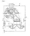
- FIG. 1 is a diagram showing an optical system of a liquid crystal projector 30, etc., of this embodiment.
- An illuminating device 1 is formed of a first lamp 1a, a second lamp 1b, and a mirror 2 arranged between the lamps 1a, 1b.
- Each lamp is formed of an ultra-high pressure mercury lamp, a metal halide lamp, a xenon lamp, etc., and its irradiated light is collimated by a parabolic reflector before being exited therefrom. The exited light is introduced to an integrator lens 4.
- the integrator lens 4 is constituted of a pair of fly eye's lenses 4a, 4b, and each pair of the lenses introduces light emitted from the illuminating device 1 to an entire surface of a liquid crystal display panel described later.
- the integrator lens 4 evens off partial luminance non-uniformity existing in the illuminating device 1, and decreases a difference between a light amount in a screen (panel) center and that on a peripheral side.
- the light that passes through the integrator lens 4 passes through a polarization conversion system 5 and a condenser lens 6, and thereafter, is introduced to a first dichroic mirror 7.
- the polarization conversion system 5 is constituted of a polarization beam splitter array (Hereinafter, referred to as a PBS array).
- the PBS array is provided with a polarized light separating surface, and a retardation plate (1/2 ⁇ plate).
- Each polarized light separating surface of the PBS array transmits P-polarized light, for example, out of light from the integrator lens 4, and changes an optical path of S-polarized light by 90 degrees.
- the S-polarized light having the optical path changed is reflected by an adjacent polarized light separating surface, and is directly exited therefrom.
- the P-polarized light that passed through the polarized light separating surface is converted into the S-polarized light by the retardation plate provided on a front side (light-exit side) of the polarized light separating surface, and is exited therefrom. That is, in this case, approximately all light is converted into the S-polarized light.
- the first dichroic mirror 7 transmits light in a red wavelength band, and reflects light in a cyan (green + blue) wavelength band.
- the light in a red wavelength band passing through the first dichroic mirror 7 enters a concave lens 8, and is reflected by a reflection mirror 9.
- an optical path is changed.
- the light of red color reflected by the reflection mirror 9 enters a lens 10, and passes through a red color-use transmission-type liquid crystal display panel 31.
- the light of red color is optically modulated.
- light in a cyan wavelength band reflected by the first dichroic mirror 7 enters a concave lens 11, and thereafter, is introduced to a second dichroic mirror 12.
- the second dichroic mirror 12 transmits light in a blue wavelength band, and reflects light in a green wavelength band.
- the light in a green wavelength band reflected by the second dichroic mirror 12 enters a lens 13, and thereafter, is introduced to a green color-use transmission-type liquid crystal display panel 32.
- the light in a green wavelength band is optically modulated.
- the light in a blue wavelength band passing through the second dichroic mirror 12 enters a relay lens 14, a reflection mirror 15, a relay lens 16, a reflection mirror 17 and a relay lens 18, and thereafter, is introduced to a blue color-use transmission-type liquid crystal display panel 33.
- the light in a blue wavelength band is optically modulated.
- Each liquid crystal display panel 31, 32, or 33 is formed of being provided with incidence-side polarizers 31a, 32a, and 33a, panel portions 31b, 32b, and 33b formed by sealing liquid crystal between a pair of glass plates (on which a pixel electrode and an alignment film are formed), and exit-side polarizers 31c, 32c, and 33c.
- the modulated light (image light of respective colors) modulated by passing through the liquid crystal display panels 31, 32, and 33 is combined by a cross dichroic prism 19, and as a result, is changed to full-color image light.
- This full-color image light is projected by a projection lens 20, and displayed on a screen not shown.
- a duct 60 is arranged inside a main body of the liquid crystal projector 30.
- the duct 60 is connected to an air-intake port formed on a side surface of the main body, for example.
- a filter 61 for removing dust in outside air is mounted at the air-intake port.
- an intake fan 46A is provided inside the duct 60, so that the outside air is drawn inside the main body. The drawn outside air passes through the duct 60, and is blown onto an object (the lamp, the liquid crystal display panel, etc.) to be cooled.
- an air-volume sensor (air-current amount sensor) 49 is provided inside the duct 60.
- a Coriolis mass current-velocity sensor, a swirl-type air-current amount sensor, a sensor for detecting an air current amount by measuring a temperature distribution changing depending on a current of winds or air, etc. may be used.
- a barometric pressure sensor 47 (see Figure 2 , too) is provided on an outside of the duct 60, which is within the main body of the liquid crystal projector 30.
- a sensor using a semiconductor pressure-sensitive element may be adopted, for example.
- an exhaust port is provided, and in the vicinity of this exhaust port, an exhaust fan 46B is provided.
- the exhaust fan 46B exhausts air inside the main body of the liquid crystal projector 30 to outside the main body.
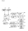
- FIG. 2 is a block chart showing a video process system and a fan control system in the liquid crystal projector 30.
- a video signal processing circuit 41 inputs a video signal, and subjects the input signal to a frequency conversion (conversion of the number of scanning lines), a gamma correction process in view of added voltage - light-transmissible characteristic of the liquid crystal display panel, and other processes, and applies this corrected video signal (video data) to the liquid crystal driving circuit 42.
- the liquid crystal driving circuit 42 drives the liquid crystal display panels 31, 32, and 33 based on the video signal.
- a system control circuit 40 controls operations of an intake fan power 45A, an exhaust fan power 45B, etc.
- the intake fan power 45A supplies power to the intake fan 46A.
- the exhaust fan power 45B supplies power to an exhaust fan 46B.
- Barometric pressure data that the barometric pressure sensor 47 outputs is input into the system control circuit 40, and air-volume data that the air-volume sensor 49 outputs, too, is input into the system control circuit 40.
- the system control circuit 40 is provided with a table storing portion (a memory) 40a.
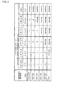
- a control table shown in Figure 3 is stored in the table storing portion 40a.
- the control table defines an added voltage value to the fan power set by a barometric pressure value and an air-volume value.
- the voltage value to be added is voltage added to a normally set voltage value, and in this embodiment, is set within a range from 0 (zero) to 6 V (volts).
- the normally set voltage value is fan driving voltage read-out from a table not shown based on a temperature detected by a temperature sensor not shown, for example.
- the added voltage value is added to a voltage value that is determined by the outside temperature and supplied to the fan power.
- the air-volume data (voltage value) of the air-volume sensor 49 is low, this indicates that the filter 61 is clogged, and thus, a current of the air inside the duct 60 becomes weak.
- the barometric pressure is low, this indicates that although the speed of rotations of the fans is the same, a force of wind becomes weak because the air becomes thin. That is, the lower the air volume, and the lower the barometric pressure, the larger the added voltage is set.
- the air volume is from 1.90 m 3 /s to 1.66 m 3 /s
- the barometric pressure value is from 966 hPa (hectopascals) to 900 hPa (hectopascals)
- 6 V volts
- the system control circuit 40 supplies to the control table measured air-volume data and barometric pressure data (both are digital data) as a reading-out address. Then, the voltage value to be added regarding the fan power is read out from the control table.
- the system control circuit 40 drives the fan based on the voltage value in which the voltage value to be added is added to the normally set voltage value.
- the system control circuit 40 is to issue a warning.
- the warning is issued by blinking a LED 50 provided on an operating panel (not shown), for example. It is, of course, possible to exhibit a warning display on a message-use display panel, or to issue a warning sound by a buzzer, etc.
- the liquid crystal projector 30 is provided with a temperature sensor not shown, and the system control circuit 40 may select one control table out of a plurality of the control tables based on temperature data from this sensor.
- the control table shown in Figure 3 is a table to be selected when the outside temperature is within a range of 27 degrees centigrade to 30 degrees centigrade, and in addition, on the table to be selected when the outside temperature is within a range of 25 degrees centigrade to 27 degrees centigrade, the "warning" may be set under a condition that the air volume is from 1.90 m 3 /s to 1.66 m 3 /s, and the barometric pressure value is from 966hPa (hectopascals) to 900hPa (hectopascals); for example. That is, an outputting condition of the warning may differ depending on the outside temperature.
- a three-panel liquid crystal projector using the liquid crystal display panel is shown.
- the present invention is applicable to a liquid crystal projector, etc., provided with another image light generating system.
Landscapes
- Engineering & Computer Science (AREA)
- Multimedia (AREA)
- Signal Processing (AREA)
- Projection Apparatus (AREA)
- Liquid Crystal (AREA)
Claims (2)
- Affichage de vidéo par projection pour appliquer une modulation optique à une lumière émise à partir d'une source de lumière, par un modulateur de lumière, et projeter une image de lumière obtenue par cette modulation optique, comprenant ;
un moyen de refroidissement à air (46A, 46B) pour refroidir l'intérieur de l'affichage par l'air ;
un filtre (61) prévu à un orifice d'admission d'air extérieur ;
un conduit (60) raccordé à l'orifice d'admission d'air extérieur ; et
un capteur de débit d'air (49) pour détecter le volume d'air aspiré par l'orifice d'admission d'air extérieur, le détecteur de débit d'air étant placé dans le conduit (60) ;
caractérisé par :un capteur de pression barométrique (47) pour détecter la pression atmosphérique, le capteur de pression barométrique étant placé à l'extérieur du conduit ;une mémoire (40a) stockant une table dans laquelle des instructions d'avertissement, déterminées par une valeur de débit d'air et une valeur de pression atmosphérique et un contenu de commande concernant une puissance de refroidissement du moyen de refroidissement à air déterminée par la valeur de débit d'air et la valeur de pression atmosphérique, sont définies ; etun contrôleur (40) pour lire les informations de la table sur la base d'une valeur de débit d'air détectée par le capteur de débit d'air et une valeur de pression atmosphérique détectée par le capteur de pression barométrique, et engendrer un signal d'avertissement lorsque l'information lue dans la table est une instruction d'avertissement. - Affichage de vidéo par projection selon la revendication 1, dans lequel la condition d'émission d'avertissement diffère en fonction d'une température extérieure.
Applications Claiming Priority (1)
| Application Number | Priority Date | Filing Date | Title |
|---|---|---|---|
| JP2004278743A JP2006091612A (ja) | 2004-09-27 | 2004-09-27 | 投写型映像表示装置 |
Publications (2)
| Publication Number | Publication Date |
|---|---|
| EP1640797A1 EP1640797A1 (fr) | 2006-03-29 |
| EP1640797B1 true EP1640797B1 (fr) | 2008-05-07 |
Family
ID=35462542
Family Applications (1)
| Application Number | Title | Priority Date | Filing Date |
|---|---|---|---|
| EP05020843A Active EP1640797B1 (fr) | 2004-09-27 | 2005-09-23 | Affichage de vidéo par projection |
Country Status (5)
| Country | Link |
|---|---|
| US (1) | US7527680B2 (fr) |
| EP (1) | EP1640797B1 (fr) |
| JP (1) | JP2006091612A (fr) |
| CN (1) | CN1755515B (fr) |
| DE (1) | DE602005006491D1 (fr) |
Families Citing this family (23)
| Publication number | Priority date | Publication date | Assignee | Title |
|---|---|---|---|---|
| JP2006091611A (ja) * | 2004-09-27 | 2006-04-06 | Sanyo Electric Co Ltd | 投写型映像表示装置 |
| JP5313444B2 (ja) | 2006-10-03 | 2013-10-09 | Necディスプレイソリューションズ株式会社 | 光源ランプ冷却装置と投射型表示装置 |
| US8403498B2 (en) | 2007-04-12 | 2013-03-26 | Panasonic Corporation | Projector, and its filter renewal control method |
| JP4826957B2 (ja) * | 2007-05-31 | 2011-11-30 | Necディスプレイソリューションズ株式会社 | 映像機器および電源制御方法 |
| JP4407726B2 (ja) | 2007-07-04 | 2010-02-03 | セイコーエプソン株式会社 | プロジェクタ、および制御方法 |
| JP5076721B2 (ja) * | 2007-08-08 | 2012-11-21 | ソニー株式会社 | プロジェクタおよびその制御方法 |
| JP5130824B2 (ja) * | 2007-08-10 | 2013-01-30 | セイコーエプソン株式会社 | プロジェクタおよび報知映像投写方法 |
| JP5216280B2 (ja) * | 2007-08-23 | 2013-06-19 | 三洋電機株式会社 | フィルタ目詰まり検知機構及びそれを用いた投写型映像表示装置 |
| US8292980B2 (en) * | 2008-09-26 | 2012-10-23 | Panasonic Corporation | Dust capture device and projection type image display apparatus |
| US8662674B2 (en) * | 2009-03-26 | 2014-03-04 | Nec Display Solutions, Ltd. | Method for controlling cooling device, cooling device, and projection-type display device |
| EP2390385B1 (fr) | 2010-05-25 | 2015-05-06 | Permelec Electrode Ltd. | Anode pour électrolyse et son procédé de fabrication |
| CN103080835B (zh) * | 2010-08-24 | 2015-05-27 | Nec显示器解决方案株式会社 | 图像显示设备及光源冷却方法 |
| JP5643030B2 (ja) * | 2010-08-30 | 2014-12-17 | 三洋電機株式会社 | 投写型表示装置 |
| JP2012128282A (ja) * | 2010-12-16 | 2012-07-05 | Sanyo Electric Co Ltd | 投写型映像表示装置 |
| JP5790060B2 (ja) * | 2011-03-25 | 2015-10-07 | 富士ゼロックス株式会社 | 画像形成装置 |
| CN103197495B (zh) * | 2012-01-04 | 2015-06-10 | 中强光电股份有限公司 | 气体过滤模块及投影装置 |
| JP6168387B2 (ja) * | 2013-02-26 | 2017-07-26 | 株式会社リコー | 光源装置及びこれを備えた画像投射装置 |
| JP2014209183A (ja) * | 2013-03-27 | 2014-11-06 | セイコーエプソン株式会社 | エアフィルター及びプロジェクター |
| JP2015194716A (ja) * | 2014-03-17 | 2015-11-05 | セイコーエプソン株式会社 | 冷却装置、プロジェクター |
| JP6265831B2 (ja) * | 2014-05-22 | 2018-01-24 | 三菱電機株式会社 | 液晶表示装置 |
| CN107153321B (zh) * | 2017-07-25 | 2019-09-24 | 新乡医学院 | 一种长时间高稳定的lcd投影机 |
| CN107153320B (zh) * | 2017-07-25 | 2019-09-24 | 新乡医学院 | 一种高对比度的lcd投影机 |
| CN111443556B (zh) * | 2019-01-16 | 2021-10-15 | 中强光电股份有限公司 | 投影机及其焦距调整方法 |
Family Cites Families (10)
| Publication number | Priority date | Publication date | Assignee | Title |
|---|---|---|---|---|
| JPH0365544U (fr) | 1989-10-25 | 1991-06-26 | ||
| US5429649A (en) * | 1992-04-14 | 1995-07-04 | Robin; Roger C. | Device for the detection of the clogging of an air filter |
| JP3159034B2 (ja) | 1996-02-22 | 2001-04-23 | タイガー魔法瓶株式会社 | 空気清浄機 |
| JP2000153121A (ja) | 1998-11-17 | 2000-06-06 | Sony Corp | フィルタの目詰まり判定制御回路 |
| JP2001209125A (ja) | 2000-01-21 | 2001-08-03 | Hitachi Ltd | 投写形表示装置 |
| JP2001222065A (ja) | 2000-02-07 | 2001-08-17 | Sanyo Electric Co Ltd | 冷却ファンを備えた電子機器 |
| JP2002062589A (ja) | 2000-08-16 | 2002-02-28 | Sony Corp | 目詰まり検知装置、映像表示装置および目詰まり検知方法 |
| JP2002258237A (ja) | 2001-02-27 | 2002-09-11 | Sanyo Electric Co Ltd | 液晶プロジェクタ |
| JP2003005289A (ja) | 2001-06-20 | 2003-01-08 | Fujitsu General Ltd | プロジェクタの冷却装置 |
| US7261762B2 (en) * | 2004-05-06 | 2007-08-28 | Carrier Corporation | Technique for detecting and predicting air filter condition |
-
2004
- 2004-09-27 JP JP2004278743A patent/JP2006091612A/ja active Pending
-
2005
- 2005-09-21 US US11/230,514 patent/US7527680B2/en active Active
- 2005-09-23 EP EP05020843A patent/EP1640797B1/fr active Active
- 2005-09-23 DE DE602005006491T patent/DE602005006491D1/de active Active
- 2005-09-27 CN CN2005101075364A patent/CN1755515B/zh active Active
Also Published As
| Publication number | Publication date |
|---|---|
| US7527680B2 (en) | 2009-05-05 |
| EP1640797A1 (fr) | 2006-03-29 |
| JP2006091612A (ja) | 2006-04-06 |
| CN1755515B (zh) | 2010-10-06 |
| CN1755515A (zh) | 2006-04-05 |
| DE602005006491D1 (de) | 2008-06-19 |
| US20060065125A1 (en) | 2006-03-30 |
Similar Documents
| Publication | Publication Date | Title |
|---|---|---|
| EP1640797B1 (fr) | Affichage de vidéo par projection | |
| EP1640796B1 (fr) | Affichage de vidéo par projection | |
| EP1640795B1 (fr) | Affichage de vidéo par projection | |
| US7976171B2 (en) | Projector cooling system with time dependent temperature threshold | |
| US7354159B2 (en) | Projection type video display | |
| US6783244B1 (en) | Display apparatus | |
| US7374289B2 (en) | Projection type video display | |
| JPH07152009A (ja) | 液晶プロジェクタ | |
| US20090033879A1 (en) | Projector apparatus and control method for projector apparatus | |
| US20050041222A1 (en) | Projector | |
| JP2007047843A (ja) | 投写型映像表示装置 | |
| JP2000081667A (ja) | 投射型表示装置 | |
| JP4151521B2 (ja) | プロジェクタ | |
| JP2004145126A (ja) | 光学エンジン及び投射型表示装置 | |
| JP2009188040A (ja) | 電気機器及びプロジェクタ | |
| JP2006145898A (ja) | プロジェクタ | |
| JP2010048885A (ja) | 投写型映像表示装置 | |
| JPH08201916A (ja) | プロジェクタ装置 | |
| JP2007206604A (ja) | プロジェクタ | |
| JP2884550B2 (ja) | 投影型映像表示装置 | |
| JP2007219153A (ja) | プロジェクタ | |
| JP2007121554A (ja) | 投射型表示装置及びそれに用いられるプリズムユニット | |
| JP2007122002A (ja) | 投射型表示装置及びそれに用いられるプリズムユニット |
Legal Events
| Date | Code | Title | Description |
|---|---|---|---|
| PUAI | Public reference made under article 153(3) epc to a published international application that has entered the european phase |
Free format text: ORIGINAL CODE: 0009012 |
|
| AK | Designated contracting states |
Kind code of ref document: A1 Designated state(s): AT BE BG CH CY CZ DE DK EE ES FI FR GB GR HU IE IS IT LI LT LU LV MC NL PL PT RO SE SI SK TR |
|
| AX | Request for extension of the european patent |
Extension state: AL BA HR MK YU |
|
| 17P | Request for examination filed |
Effective date: 20060329 |
|
| AKX | Designation fees paid |
Designated state(s): DE FR GB |
|
| GRAP | Despatch of communication of intention to grant a patent |
Free format text: ORIGINAL CODE: EPIDOSNIGR1 |
|
| GRAS | Grant fee paid |
Free format text: ORIGINAL CODE: EPIDOSNIGR3 |
|
| GRAA | (expected) grant |
Free format text: ORIGINAL CODE: 0009210 |
|
| AK | Designated contracting states |
Kind code of ref document: B1 Designated state(s): DE FR GB |
|
| REG | Reference to a national code |
Ref country code: GB Ref legal event code: FG4D |
|
| REF | Corresponds to: |
Ref document number: 602005006491 Country of ref document: DE Date of ref document: 20080619 Kind code of ref document: P |
|
| PLBE | No opposition filed within time limit |
Free format text: ORIGINAL CODE: 0009261 |
|
| STAA | Information on the status of an ep patent application or granted ep patent |
Free format text: STATUS: NO OPPOSITION FILED WITHIN TIME LIMIT |
|
| 26N | No opposition filed |
Effective date: 20090210 |
|
| REG | Reference to a national code |
Ref country code: GB Ref legal event code: 746 Effective date: 20130617 |
|
| REG | Reference to a national code |
Ref country code: DE Ref legal event code: R084 Ref document number: 602005006491 Country of ref document: DE Effective date: 20130612 |
|
| REG | Reference to a national code |
Ref country code: FR Ref legal event code: PLFP Year of fee payment: 12 |
|
| REG | Reference to a national code |
Ref country code: FR Ref legal event code: PLFP Year of fee payment: 13 |
|
| REG | Reference to a national code |
Ref country code: FR Ref legal event code: PLFP Year of fee payment: 14 |
|
| REG | Reference to a national code |
Ref country code: DE Ref legal event code: R082 Ref document number: 602005006491 Country of ref document: DE Representative=s name: GLAWE DELFS MOLL PARTNERSCHAFT MBB VON PATENT-, DE |
|
| PGFP | Annual fee paid to national office [announced via postgrant information from national office to epo] |
Ref country code: GB Payment date: 20230803 Year of fee payment: 19 |
|
| PGFP | Annual fee paid to national office [announced via postgrant information from national office to epo] |
Ref country code: FR Payment date: 20230808 Year of fee payment: 19 Ref country code: DE Payment date: 20230802 Year of fee payment: 19 |