EP1640796B1 - Affichage de vidéo par projection - Google Patents
Affichage de vidéo par projection Download PDFInfo
- Publication number
- EP1640796B1 EP1640796B1 EP05020842A EP05020842A EP1640796B1 EP 1640796 B1 EP1640796 B1 EP 1640796B1 EP 05020842 A EP05020842 A EP 05020842A EP 05020842 A EP05020842 A EP 05020842A EP 1640796 B1 EP1640796 B1 EP 1640796B1
- Authority
- EP
- European Patent Office
- Prior art keywords
- driving
- air
- cooling means
- light
- voltages
- Prior art date
- Legal status (The legal status is an assumption and is not a legal conclusion. Google has not performed a legal analysis and makes no representation as to the accuracy of the status listed.)
- Active
Links
- 238000001816 cooling Methods 0.000 claims description 43
- 230000003287 optical effect Effects 0.000 claims description 12
- 239000004973 liquid crystal related substance Substances 0.000 description 28
- 238000006243 chemical reaction Methods 0.000 description 4
- 238000000034 method Methods 0.000 description 3
- 230000010287 polarization Effects 0.000 description 3
- 238000010586 diagram Methods 0.000 description 2
- 239000000428 dust Substances 0.000 description 2
- 230000004397 blinking Effects 0.000 description 1
- 239000003086 colorant Substances 0.000 description 1
- 230000007423 decrease Effects 0.000 description 1
- 230000001419 dependent effect Effects 0.000 description 1
- 238000011161 development Methods 0.000 description 1
- 230000018109 developmental process Effects 0.000 description 1
- 239000011521 glass Substances 0.000 description 1
- QSHDDOUJBYECFT-UHFFFAOYSA-N mercury Chemical compound [Hg] QSHDDOUJBYECFT-UHFFFAOYSA-N 0.000 description 1
- 229910052753 mercury Inorganic materials 0.000 description 1
- 229910001507 metal halide Inorganic materials 0.000 description 1
- 150000005309 metal halides Chemical class 0.000 description 1
- 230000002093 peripheral effect Effects 0.000 description 1
- 238000007789 sealing Methods 0.000 description 1
- 239000004065 semiconductor Substances 0.000 description 1
- 229910052724 xenon Inorganic materials 0.000 description 1
- FHNFHKCVQCLJFQ-UHFFFAOYSA-N xenon atom Chemical compound [Xe] FHNFHKCVQCLJFQ-UHFFFAOYSA-N 0.000 description 1
Images

Classifications
-
- H—ELECTRICITY
- H04—ELECTRIC COMMUNICATION TECHNIQUE
- H04N—PICTORIAL COMMUNICATION, e.g. TELEVISION
- H04N9/00—Details of colour television systems
- H04N9/12—Picture reproducers
- H04N9/31—Projection devices for colour picture display, e.g. using electronic spatial light modulators [ESLM]
- H04N9/3141—Constructional details thereof
- H04N9/3144—Cooling systems
-
- H—ELECTRICITY
- H04—ELECTRIC COMMUNICATION TECHNIQUE
- H04N—PICTORIAL COMMUNICATION, e.g. TELEVISION
- H04N9/00—Details of colour television systems
- H04N9/12—Picture reproducers
- H04N9/31—Projection devices for colour picture display, e.g. using electronic spatial light modulators [ESLM]
- H04N9/3141—Constructional details thereof
Definitions
- the present invention relates to a projection type video display such as a liquid crystal projector, etc.
- a projection type video display needs to be provided with a high-intensity light source. For this, it is needed to prepare measures against heat generated from the high-intensity light source itself, or heat generated at a time that the light is absorbed by a polarizer of a liquid crystal panel or various kinds of optical components. From the past, an intake and exhaust are performed by rotating a cooling fan by a motor so as to release the heat to outside the video display (see Japanese Patent Laying-open No. 2001-222065 ).
- a filter is provided at an air-intake port for removing a dust in the outside air, and if this filter is clogged, an appropriate cooling control cannot be realized.
- Patent Abstracts of Japan, vol. 2002. no. 06, June 4, 2002 & JP 2002 062589 A discloses a video display device provided with a fan and a dust-proof filter in a suction port.
- a controller counts a rotation signal outputted from a motor driving the fan, and when the counting number exceeds a specified value, the controller judges this as clogging off the filter.
- Patent Abstracts of Japan, vol. 2000, no. 25, April 12, 2001 & JP 2001 209125 A describes a projection type display device comprising a speed change fan and a wind velocity sensor at a discharge port. The speed of revolution of the speed change fan is controlled and quick clogging off a filter is prevented.
- Patent Abstracts of Japan, vol. 2000, no. 09, October 13, 2000 & JP 2000 153121 A discloses a filter clogging control circuit in which clogging of the filter is detected only by detecting the number of rotations of a drive motor of a cooling fan without using a pressure sensor or a temperature sensor.
- a projection type video display is a projection type video display for applying an optical modulation to light emitted from a light source by a light valve, and projecting image light obtained by this optical modulation, and comprises an air-cooling means for cooling inside the display by air, a filter provided at an outside-air intake port, an air-volume sensor for detecting a volume of air drawn from the outside-air intake port, a table on which a control content determined based on an air-volume value is defined, and a control means for controlling a cooling power of the air-cooling means by obtaining the control content from the table based on air volume data from the air-volume sensor (Hereinafter, referred to as a first configuration in this section).
- the control means controls a cooling power of the air-cooling means by the control content based on the air-volume data, so that even in a case that the filter is clogged, the control means is capable of performing a cooling control as appropriate as possible.
- a projection type video display is a projection type video display for applying an optical modulation to light emitted from a light source by a light valve, and projecting image light obtained by this optical modulation, and comprises an air-cooling means for cooling inside the device by air, a filter provided at an outside-air intake port, an air-volume sensor for detecting a volume of air taken in from the outside-air intake port, a barometric sensor for detecting a barometric pressure, a table on which a control content determined by an air volume value and a barometric-pressure value is defined, and a control means for controlling a cooling power of the air-cooling means by obtaining the control content from the table based on air volume data from the air-volume sensor and barometric-pressure data from the barometric pressure sensor (Hereinafter, referred to as a second configuration in this section).
- the control means controls a cooling power of the air-cooling means by the control content based on the air-volume data, so that even in a case that the filter is clogged, the control means is capable of performing a cooling control as appropriate as possible.
- a projection type video display may comprise a temperature sensor for detecting outside temperature, and a table on which the control content of the air-cooling means determined by temperature is defined, in which the control means may obtain the control content from the table based on temperature data from the temperature sensor, and may control the air-cooling means based on the control content in which the control content based on the air volume data is the control content based on the temperature data.
- a projection type video display may comprise a temperature sensor for detecting outside temperature, and a table on which the control content of the air-cooling means is defined by temperature, in which the control means may obtain the control content from the table based on temperature data from the temperature sensor, and may control the air-cooling means based on a control content in which the control content based on the air volume data and barometric-pressure data are the control content based on the temperature data.
- the table may be formed of a normal mode-use table, and an economy mode-use table.
- the table may be formed of at least a table for a time of driving the light source by first electric power, and a table for a time of driving the light source by second electric power.
- a projection type video display may comprise a plurality of light sources as the light source, in which the table is formed of at least a table for a time that all the light sources are turned on, and a table for a time that one or a few light sources are turned on.
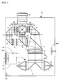
- FIG. 1 is a diagram showing an optical system of a liquid crystal projector 30, etc., of this embodiment.
- An illuminating device 1 is formed of a first lamp 1a, a second lamp 1b, and mirrors 2 arranged between the lamps 1a, 1b.
- Each lamp is formed of an ultra-high pressure mercury lamp, a metal halide lamp, a xenon lamp, etc., and light emitted from each lamp is converted into collimated light by a parabolic reflector. Then, the light is guided to an integrator lens 4.
- the integrator lens 4 is constituted of a pair of fly's eye lenses 4a, 4b, and each pair of the lenses introduces light emitted from the illuminating device 1 to an entire surface of a liquid crystal display panel described later.
- the integrator lens 4 evens off partial luminance non-uniformity existing in the illuminating device 1, and decreases a difference between a light amount in a screen (panel) center and that on a peripheral side.
- the light that passes through the integrator lens 4 passes through a polarization conversion system 5 and a condenser lens 6, and thereafter, is introduced to a first dichroic mirror 7.
- the polarization conversion system 5 is constituted of a polarization beam splitter array (Hereinafter, referred to as a PBS array).
- the PBS array is provided with a polarized light separating surface, and a retardation plate (1/2 ⁇ plate).
- Each polarized light separating surface of the PBS array transmits P-polarized light, for example, out of light from the integrator lens 4, and changes an optical path of S-polarized light by 90 degrees.
- the S-polarized light having the optical path changed is reflected by an adjacent polarized light separating surface, and is directly exited therefrom.
- the P-polarized light that passed through the polarized light separating surface is converted into the S-polarized light by the retardation plate provided on a front side (light-exit side) of the polarized light separating surface, and is exited therefrom. That is, in this case, approximately all light is converted into the S-polarized light.
- the first dichroic mirror 7 transmits light in a red wavelength band, and reflects light in a cyan (green + blue) wavelength band.
- the light in a red wavelength band passing through the first dichroic mirror 7 enters a concave lens 8, and is reflected by a reflection mirror 9.
- an optical path is changed.
- the light of red color reflected by the reflection mirror 9 enters a lens 10, and passes through a red color-use transmission-type liquid crystal display panel 31.
- the light of red color is optically modulated.
- light in a cyan wavelength band reflected by the first dichroic mirror 7 enters a concave lens 11, and thereafter, is introduced to a second dichroic mirror 12.
- the second dichroic mirror 12 transmits light in a blue wavelength band, and reflects light in a green wavelength band.
- the light in a green wavelength band reflected by the second dichroic mirror 12 enters a lens 13, and thereafter, is introduced to a green color-use transmission-type liquid crystal display panel 32.
- the light in a green wavelength band is optically modulated.
- the light in a blue wavelength band passing through the second dichroic mirror 12 enters a relay lens 14, a reflection mirror 15, a relay lens 16, a reflection mirror 17 and a relay lens 18, and thereafter, is introduced to a blue color-use transmission-type liquid crystal display panel 33.
- the light in a blue wavelength band is optically modulated.
- Each liquid crystal display panel 31, 32, or 33 is formed of being provided with incidence-side polarizers 31a, 32a, and 33a, panel portions 31b, 32b, and 33b formed by sealing liquid crystal between a pair of glass plates (on which a pixel electrode and an alignment film are formed), and exit-side polarizers 31c, 32c, and 33c.
- the modulated light (image light of respective colors) modulated by passing through the liquid crystal display panels 31, 32, and 33 is combined by a cross dichroic prism 19, and as a result, is changed to full-color image light.
- This full-color image light is projected by a projection lens 20, and displayed on a screen not shown.
- a duct 60 is arranged inside a main body of the liquid crystal projector 30.
- the duct 60 is connected to an air-intake port formed on a side surface of the main body, for example.
- a filter 61 for removing dust in outside air is mounted at the air-intake port.
- an intake fan 46A is provided inside the duct 60, so that the outside air is drawn inside the main body. The drawn outside air passes through the duct 60, and is blown onto an object (the lamp, the liquid crystal display panel, etc.) to be cooled.
- an air-volume sensor (air-current amount sensor) 49 is provided inside the duct 60.
- a Coriolis mass current-velocity sensor, a swirl-type air-current amount sensor, a sensor for detecting an air current amount by measuring a temperature distribution changing depending on a current of winds or air, etc. may be used.
- a barometric pressure sensor 47 (see Figure 2 , too) is provided on an outside of the duct 60, which is within the main body of the liquid crystal projector 30.
- a sensor using a semiconductor pressure-sensitive element may be adopted, for example.
- an exhaust port is provided, and in the vicinity of this exhaust port, an exhaust fan 46B is provided.
- the exhaust fan 46B exhausts air inside the main body of the liquid crystal projector 30 to outside the main body.
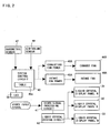
- FIG. 2 is a block chart showing a video process system and a fan control system in the liquid crystal projector 30.
- a video signal processing circuit 41 inputs a video signal, and subjects the input signal to a frequency conversion (conversion of the number of scanning lines), a gamma correction process in view of added voltage-light-transmissible characteristic of the liquid crystal display panel, and other processes, and applies this corrected video signal (video data) to the liquid crystal driving circuit 42.
- the liquid crystal driving circuit 42 drives the liquid crystal display panels 31, 32, and 33 based on the video signal.
- a system control circuit 40 controls operations of an intake fan power supply 45A, an exhaust fan power supply 45B, etc.
- the intake fan power supply 45A supplies electric power to the intake fan 46A.
- the exhaust fan power supply 45B supplies electric power to the exhaust fan 46B.
- Barometric-pressure data that the barometric pressure sensor 47 outputs is input into the system control circuit 40, and air-volume data that the air-volume sensor 49 outputs, too, is input into the system control circuit 40.
- the system control circuit 40 is provided with a table storing portion (a memory) 40a.
- a control table shown in Figure 3 is stored in the table storing portion 40a.
- the control table defines a voltage value to be added to the fan power supply set by a barometric-pressure value and an air-volume value.
- the voltage value to be added is voltage added to a normally set voltage value, and in this embodiment, is set within a range from 0 (zero) V (volt) to 6 V.
- the normally set voltage value is fan driving voltage read-out from a table not shown based on temperature detected by a temperature sensor not shown, for example.
- the voltage value to be added is applied to a voltage value that is determined by the outside temperature and supplied to the fan power supply.
- the air-volume data (voltage value) of the air-volume sensor 49 is low, this indicates that the filter 61 is clogged, and thus, a current of the air inside the duct 60 becomes weak.
- the barometric pressure is low, this indicates that although the speed of rotations of the fans is the same, a force of air becomes weak because the air becomes thin. That is, the lower the air volume and the barometric pressure, the larger the voltage value to be added is set.
- the air volume is from 1.90 m 3 /s to 1.66 m 3 /s
- the barometric-pressure value is from 966 hPa (hectopascals) to 900 hPa, for example, 6 V are added to the normally set voltage value.
- the system control circuit 40 supplies to the control table measured air-volume data and barometric-pressure data (both are digital data) as a reading-out address. Then, the voltage value to be added to the fan power supply is read out from the control table.
- the system control circuit 40 drives the fan based on the voltage value in which the voltage value to be added is applied to the normally set voltage value.
- the system control circuit 40 is to issue a warning.
- the warning is issued by turning on or blinking a LED 50 provided on an operating panel (not shown), for example. It is, of course, possible to exhibit a warning display on a message-use display panel, or to issue a warning sound by a buzzer, etc.
- the control table may be formed of at least a table for a time of driving a light source by first power supply (300 W (Watt)), for example), and a table for a time of driving a light source by second power supply (240 W, for example). Needless to say, the control table may be formed of the table for a time of driving a light source by first power supply, the table for a time of driving a light source by second power supply, and a table for a time of driving a light source by first power supply.
- the table may be formed of at least a table for a time that all lamps are turned on (a table used in a case that four lamps, out of the four lamps, are turned on, or a table used in a case that two lamps, out of the two lamps, are turned on, for example), and a table for a time that one or a few lamps are turned on (a table used in a case that two lamps, out of four lamps, are turned on, or a table used in a case that one lamp, out of two lamps, is turned on, for example).
Landscapes
- Engineering & Computer Science (AREA)
- Multimedia (AREA)
- Signal Processing (AREA)
- Projection Apparatus (AREA)
- Liquid Crystal (AREA)
Claims (4)
- Dispositif d'affichage vidéo du type par projection destiné à appliquer une modulation optique sur une lumière émise à partir d'une source de lumière (1) par un modulateur de lumière, et à projeter une image lumineuse obtenue par cette modulation optique, comprenant :un moyen de refroidissement d'air (46) destiné à refroidir l'intérieur du dispositif d'affichage vidéo avec de l'air ;un filtre (61) formé au niveau d'un orifice d'admission d'air externe ;un capteur de débit d'air (49) destiné à détecter un débit d'air de l'air aspiré à partir de l'extérieur à partir d'un orifice d'admission d'air externe ; caractérisé parun capteur barométrique (47) destiné à détecter une pression atmosphérique ;
un capteur de température destiné à détecter une température externe ;
une mémoire (48a) mémorisant une première table dans laquelle des tensions d'attaque destinées à attaquer le moyen de refroidissement d'air déterminées par la température sont définies, et mémorisant une seconde table dans laquelle des valeurs de tension à ajouter à la tension d'attaque destinée à attaquer le moyen de refroidissement d'air déterminées par une valeur de débit d'air et une valeur de pression atmosphérique sont définies ; et
un moyen de commande (40) afin d'obtenir des tensions d'attaque destinées à attaquer le moyen de refroidissement d'air à partir de la première table sur la base de données de température à partir du capteur de température, obtenant des valeurs de tension à ajouter à la tension d'attaque destinée à attaquer le moyen de refroidissement d'air à partir de la seconde table sur la base de données de débit d'air à partir du capteur de débit d'air et des données de pression atmosphérique à partir d'un capteur barométrique, et commandant une puissance de refroidissement du moyen de refroidissement d'air (46) sur la base d'une tension d'attaque qui est produite en ajoutant les valeurs de tension à ajouter à la tension d'attaque destinée à attaquer le moyen de refroidissement d'air aux tensions d'attaque destinées à attaquer le moyen de refroidissement d'air. - Dispositif d'affichage vidéo du type par projection selon la revendication 1, dans lequel il existe au moins des tensions d'attaque destinées à attaquer le moyen de refroidissement d'air en mode d'utilisation normal et des tensions d'attaque destinées à attaquer le moyen de refroidissement d'air en mode d'utilisation économique pour les tensions d'attaque destinées à attaquer le moyen de refroidissement d'air.
- Dispositif d'affichage vidéo du type par projection selon la revendication 1 ou 2, dans lequel il existe au moins des tensions d'attaque destinées à attaquer le moyen de refroidissement d'air pendant une période d'attaque de la source de lumière par la première source d'alimentation et des tensions d'attaque destinées à attaquer le moyen de refroidissement d'air pendant une période d'attaque de la source de lumière par la seconde source de puissance pour les tensions d'attaque destinées à attaquer le moyen de refroidissement d'air.
- Dispositif d'affichage vidéo du type par projection selon l'une quelconque des revendications 1 à 3, comprenant une pluralité de sources de lumière pour la source de lumière (1), dans lequel il existe au moins des tensions d'attaque destinées à attaquer le moyen de refroidissement d'air pendant une durée pendant laquelle toutes les sources de lumière sont activées et des tensions d'attaque destinées à attaquer le moyen de refroidissement d'air pendant une durée pendant laquelle une ou quelques sources de lumière sont activées en tant que contenu de commande.
Applications Claiming Priority (1)
| Application Number | Priority Date | Filing Date | Title |
|---|---|---|---|
| JP2004278742A JP2006091611A (ja) | 2004-09-27 | 2004-09-27 | 投写型映像表示装置 |
Publications (2)
| Publication Number | Publication Date |
|---|---|
| EP1640796A1 EP1640796A1 (fr) | 2006-03-29 |
| EP1640796B1 true EP1640796B1 (fr) | 2008-02-27 |
Family
ID=35462476
Family Applications (1)
| Application Number | Title | Priority Date | Filing Date |
|---|---|---|---|
| EP05020842A Active EP1640796B1 (fr) | 2004-09-27 | 2005-09-23 | Affichage de vidéo par projection |
Country Status (5)
| Country | Link |
|---|---|
| US (1) | US7537348B2 (fr) |
| EP (1) | EP1640796B1 (fr) |
| JP (1) | JP2006091611A (fr) |
| CN (1) | CN100498511C (fr) |
| DE (1) | DE602005004974T2 (fr) |
Families Citing this family (17)
| Publication number | Priority date | Publication date | Assignee | Title |
|---|---|---|---|---|
| JP2006091610A (ja) * | 2004-09-27 | 2006-04-06 | Sanyo Electric Co Ltd | 投写型映像表示装置 |
| JP4997977B2 (ja) * | 2006-02-24 | 2012-08-15 | セイコーエプソン株式会社 | プロジェクタ |
| TWI325089B (en) * | 2007-02-16 | 2010-05-21 | Coretronic Corp | Projection apparatus and lamp module |
| JP4860533B2 (ja) * | 2007-03-30 | 2012-01-25 | Necディスプレイソリューションズ株式会社 | 投射型表示装置 |
| JP5034631B2 (ja) * | 2007-04-12 | 2012-09-26 | パナソニック株式会社 | 過熱保護装置および過熱保護装置を備えたプロジェクター |
| JP5134865B2 (ja) * | 2007-05-30 | 2013-01-30 | 三洋電機株式会社 | 冷却風量検出装置及びそれを用いた投写型映像表示装置 |
| JP4407726B2 (ja) * | 2007-07-04 | 2010-02-03 | セイコーエプソン株式会社 | プロジェクタ、および制御方法 |
| US8064200B1 (en) * | 2008-04-16 | 2011-11-22 | Cyan Optics, Inc. | Cooling a chassis by moving air through a midplane between two sets of channels oriented laterally relative to one another |
| US8155520B1 (en) | 2008-04-16 | 2012-04-10 | Cyan, Inc. | Multi-fabric shelf for a transport network |
| WO2009144815A1 (fr) * | 2008-05-30 | 2009-12-03 | Necディスプレイソリューションズ株式会社 | Filtre, élément à jet de refroidissement et procédé à jet d’air de refroidissement |
| TW201025231A (en) * | 2008-12-19 | 2010-07-01 | Formolight Technologies Inc | Adjustment and control device for display panel |
| CN101777332A (zh) * | 2009-01-14 | 2010-07-14 | 新谱光科技股份有限公司 | 一种显示面板调控装置 |
| CN102196218A (zh) * | 2010-03-01 | 2011-09-21 | 台达电子工业股份有限公司 | 投影系统及其具有投影功能的电源供应模块 |
| CN103080835B (zh) * | 2010-08-24 | 2015-05-27 | Nec显示器解决方案株式会社 | 图像显示设备及光源冷却方法 |
| CN102681311B (zh) * | 2011-03-11 | 2014-09-03 | 中强光电股份有限公司 | 控制电路与投影装置的操作方法 |
| JP2011150364A (ja) * | 2011-03-17 | 2011-08-04 | Necディスプレイソリューションズ株式会社 | 投射型表示装置 |
| JP6524608B2 (ja) * | 2013-06-20 | 2019-06-05 | セイコーエプソン株式会社 | 光源装置、プロジェクターおよび放電灯の冷却方法 |
Family Cites Families (11)
| Publication number | Priority date | Publication date | Assignee | Title |
|---|---|---|---|---|
| JP2000153121A (ja) * | 1998-11-17 | 2000-06-06 | Sony Corp | フィルタの目詰まり判定制御回路 |
| JP4017775B2 (ja) * | 1998-12-28 | 2007-12-05 | 富士通株式会社 | 投写型表示装置 |
| JP2001209125A (ja) * | 2000-01-21 | 2001-08-03 | Hitachi Ltd | 投写形表示装置 |
| JP2001222065A (ja) | 2000-02-07 | 2001-08-17 | Sanyo Electric Co Ltd | 冷却ファンを備えた電子機器 |
| JP2002062589A (ja) * | 2000-08-16 | 2002-02-28 | Sony Corp | 目詰まり検知装置、映像表示装置および目詰まり検知方法 |
| JP2002258237A (ja) | 2001-02-27 | 2002-09-11 | Sanyo Electric Co Ltd | 液晶プロジェクタ |
| JP2003005147A (ja) | 2001-06-19 | 2003-01-08 | Fujitsu General Ltd | 液晶プロジェクタ装置 |
| JP2004348109A (ja) * | 2003-04-28 | 2004-12-09 | Mitsubishi Electric Corp | 投写型表示装置 |
| TWI233529B (en) * | 2004-03-12 | 2005-06-01 | Coretronic Corp | A control method of a projection display |
| JP2006091612A (ja) * | 2004-09-27 | 2006-04-06 | Sanyo Electric Co Ltd | 投写型映像表示装置 |
| JP2006091610A (ja) * | 2004-09-27 | 2006-04-06 | Sanyo Electric Co Ltd | 投写型映像表示装置 |
-
2004
- 2004-09-27 JP JP2004278742A patent/JP2006091611A/ja active Pending
-
2005
- 2005-09-23 DE DE602005004974T patent/DE602005004974T2/de active Active
- 2005-09-23 EP EP05020842A patent/EP1640796B1/fr active Active
- 2005-09-26 US US11/234,124 patent/US7537348B2/en active Active
- 2005-09-27 CN CNB2005101068676A patent/CN100498511C/zh active Active
Also Published As
| Publication number | Publication date |
|---|---|
| DE602005004974D1 (de) | 2008-04-10 |
| EP1640796A1 (fr) | 2006-03-29 |
| JP2006091611A (ja) | 2006-04-06 |
| DE602005004974T2 (de) | 2009-03-19 |
| US20060067049A1 (en) | 2006-03-30 |
| CN1755513A (zh) | 2006-04-05 |
| CN100498511C (zh) | 2009-06-10 |
| US7537348B2 (en) | 2009-05-26 |
Similar Documents
| Publication | Publication Date | Title |
|---|---|---|
| EP1640796B1 (fr) | Affichage de vidéo par projection | |
| EP1640797B1 (fr) | Affichage de vidéo par projection | |
| EP1640795B1 (fr) | Affichage de vidéo par projection | |
| US7354159B2 (en) | Projection type video display | |
| US7976171B2 (en) | Projector cooling system with time dependent temperature threshold | |
| US7374289B2 (en) | Projection type video display | |
| US20040057020A1 (en) | Display apparatus | |
| JPH07152009A (ja) | 液晶プロジェクタ | |
| US20090033879A1 (en) | Projector apparatus and control method for projector apparatus | |
| US20050041222A1 (en) | Projector | |
| JP2007047843A (ja) | 投写型映像表示装置 | |
| US20030058410A1 (en) | Projector | |
| JP2000081667A (ja) | 投射型表示装置 | |
| JP4151521B2 (ja) | プロジェクタ | |
| JPH08201916A (ja) | プロジェクタ装置 | |
| JP2009188040A (ja) | 電気機器及びプロジェクタ | |
| JP2006145898A (ja) | プロジェクタ | |
| JP2004246178A (ja) | 光学ユニット、投射型映像表示装置及びそれに用いる偏光板 | |
| JP2007206604A (ja) | プロジェクタ | |
| JP2005077890A (ja) | 投写型映像表示装置及び照度検査調整方法 | |
| JP2009236955A (ja) | プロジェクタ | |
| JP2004245987A (ja) | プロジェクタ | |
| JP2884550B2 (ja) | 投影型映像表示装置 | |
| JP2007219153A (ja) | プロジェクタ | |
| JP2007121554A (ja) | 投射型表示装置及びそれに用いられるプリズムユニット |
Legal Events
| Date | Code | Title | Description |
|---|---|---|---|
| PUAI | Public reference made under article 153(3) epc to a published international application that has entered the european phase |
Free format text: ORIGINAL CODE: 0009012 |
|
| AK | Designated contracting states |
Kind code of ref document: A1 Designated state(s): AT BE BG CH CY CZ DE DK EE ES FI FR GB GR HU IE IS IT LI LT LU LV MC NL PL PT RO SE SI SK TR |
|
| AX | Request for extension of the european patent |
Extension state: AL BA HR MK YU |
|
| 17P | Request for examination filed |
Effective date: 20060601 |
|
| 17Q | First examination report despatched |
Effective date: 20060706 |
|
| AKX | Designation fees paid |
Designated state(s): DE FR GB |
|
| GRAP | Despatch of communication of intention to grant a patent |
Free format text: ORIGINAL CODE: EPIDOSNIGR1 |
|
| GRAS | Grant fee paid |
Free format text: ORIGINAL CODE: EPIDOSNIGR3 |
|
| GRAA | (expected) grant |
Free format text: ORIGINAL CODE: 0009210 |
|
| AK | Designated contracting states |
Kind code of ref document: B1 Designated state(s): DE FR GB |
|
| REG | Reference to a national code |
Ref country code: GB Ref legal event code: FG4D |
|
| REF | Corresponds to: |
Ref document number: 602005004974 Country of ref document: DE Date of ref document: 20080410 Kind code of ref document: P |
|
| ET | Fr: translation filed | ||
| PLBE | No opposition filed within time limit |
Free format text: ORIGINAL CODE: 0009261 |
|
| STAA | Information on the status of an ep patent application or granted ep patent |
Free format text: STATUS: NO OPPOSITION FILED WITHIN TIME LIMIT |
|
| 26N | No opposition filed |
Effective date: 20081128 |
|
| REG | Reference to a national code |
Ref country code: GB Ref legal event code: 746 Effective date: 20130617 |
|
| REG | Reference to a national code |
Ref country code: DE Ref legal event code: R084 Ref document number: 602005004974 Country of ref document: DE Effective date: 20130612 |
|
| REG | Reference to a national code |
Ref country code: FR Ref legal event code: PLFP Year of fee payment: 12 |
|
| REG | Reference to a national code |
Ref country code: FR Ref legal event code: PLFP Year of fee payment: 13 |
|
| REG | Reference to a national code |
Ref country code: FR Ref legal event code: PLFP Year of fee payment: 14 |
|
| REG | Reference to a national code |
Ref country code: DE Ref legal event code: R082 Ref document number: 602005004974 Country of ref document: DE Representative=s name: GLAWE DELFS MOLL PARTNERSCHAFT MBB VON PATENT-, DE |
|
| PGFP | Annual fee paid to national office [announced via postgrant information from national office to epo] |
Ref country code: GB Payment date: 20230803 Year of fee payment: 19 |
|
| PGFP | Annual fee paid to national office [announced via postgrant information from national office to epo] |
Ref country code: FR Payment date: 20230808 Year of fee payment: 19 Ref country code: DE Payment date: 20230802 Year of fee payment: 19 |