EP1637664A1 - Profil de base pour panneaux de revêtement de murs de bâtiments, et procédé de fixation associé. - Google Patents
Profil de base pour panneaux de revêtement de murs de bâtiments, et procédé de fixation associé. Download PDFInfo
- Publication number
- EP1637664A1 EP1637664A1 EP04022144A EP04022144A EP1637664A1 EP 1637664 A1 EP1637664 A1 EP 1637664A1 EP 04022144 A EP04022144 A EP 04022144A EP 04022144 A EP04022144 A EP 04022144A EP 1637664 A1 EP1637664 A1 EP 1637664A1
- Authority
- EP
- European Patent Office
- Prior art keywords
- web
- edge
- profile strip
- support web
- profile
- Prior art date
- Legal status (The legal status is an assumption and is not a legal conclusion. Google has not performed a legal analysis and makes no representation as to the accuracy of the status listed.)
- Withdrawn
Links
Images


Classifications
-
- E—FIXED CONSTRUCTIONS
- E04—BUILDING
- E04F—FINISHING WORK ON BUILDINGS, e.g. STAIRS, FLOORS
- E04F13/00—Coverings or linings, e.g. for walls or ceilings
- E04F13/02—Coverings or linings, e.g. for walls or ceilings of plastic materials hardening after applying, e.g. plaster
- E04F13/04—Bases for plaster
- E04F13/06—Edge-protecting borders
- E04F13/068—Edge-protecting borders combined with mesh material or the like to allow plaster to bond therewith
-
- E—FIXED CONSTRUCTIONS
- E04—BUILDING
- E04F—FINISHING WORK ON BUILDINGS, e.g. STAIRS, FLOORS
- E04F13/00—Coverings or linings, e.g. for walls or ceilings
- E04F13/02—Coverings or linings, e.g. for walls or ceilings of plastic materials hardening after applying, e.g. plaster
- E04F13/04—Bases for plaster
- E04F13/06—Edge-protecting borders
- E04F2013/065—Edge-protecting borders for lower edges of outer insulation layers
Definitions
- the invention relates to a profile strip, in particular base profile strip, for cover panels of building walls, in particular thermal insulation panels for full thermal insulation of buildings, and a method for attaching cover plates to building walls.
- Known profile strips of this type have a support web for the cover plates, to which a fastening web and an edge web are integrally formed.
- the fastening bar is intended for fastening the profile strip to a building wall.
- the edge web serves as edge protection for the outer edge of the cover plates resting on the support web.
- it forms an investment and anchoring surface for a mesh fabric, which is placed after attachment of the cover plates on the outer surface of the formed cover layer and fixed by means of a spatula adhesive on the cover layer and the edge web. Subsequently, a plaster layer is applied.
- the anchoring of the mesh fabric to the edge web has proved to be problematic with the usual filler adhesives as well as the anchoring of the plaster layer to the edge web.
- the adhesion of the adhesive or the plaster on the smooth edge web surfaces is too low, with the result of Putzabplatzungen. Even openings or depressions in the edge web lead to no satisfactory adhesion of filler or plaster.
- the present invention has for its object to provide an improved profile strip for cover plates and a method for attaching cover plates, with the or the aforementioned problems and disadvantages are at least partially overcome.
- the adhesion of putty and plaster layer to the profile strip and the alignment of adjacent profile strips to each other should be improved.
- an appropriate for the attachment of the moldings on a building wall impact dowels should be specified.
- the profile strips can also generally be used as edge strips of covering systems, for example also on the side or at the upper edge of covering systems.
- the edge web serves inter alia as edge protection for lying on the support surface of the support web cover plates and for conditioning and / or anchoring a fabric, in particular a mesh fabric, such as a glass fiber fabric, which is placed after attachment of the cover plates on the outer surface of the formed cover layer and by means of an adhesive, in particular putty adhesive, is attached to the cover layer and the edge web.
- the fabric serves to anchor a subsequently applied plaster layer.
- the edge web is usually at least in sections oriented parallel to the fastening web, preferably edge web and fastening web extend on the same side of the support web away from this.
- the cover plates are inserted, in particular positive and / or non-positive, in such a way that their narrow side rests on the support surface of the support web.
- the mounting bar and the edge bar When attached to the building wall, the mounting bar and the edge bar are usually parallel to the building wall, i. vertical, aligned.
- the fastening bar rests against the building wall.
- the support bar is oriented substantially horizontally (with the exception of a slight incline to ensure the drainage of condensation), with the attachment and edge bar normally extending upwards away from it.
- the edge web can also extend down from the support web away.
- the cleaning bar preferably extends away from the attachment web on the side facing away from the attachment web, i. in normal mounting position when attached to a building wall down from the support web away. He is at least partially aligned obliquely to the support web, and expediently such that it extends from the building wall away from the support web, when attached to the building wall. In this way it can be achieved that the distance of the plasterboard of the building wall or fastening web is at least partially larger than the corresponding distance of the edge web. This means that the plasterboard at least partially protrudes further over the building wall or the fastening web as the edge web. The outermost (i.e., farthest from the building wall) edge of the plasterboard thus forms a trigger edge for the plaster to be applied.
- the undercut longitudinal groove provides an additional anchoring for the adhesive (in particular spatula adhesive) of the applied grid fabric and for the plaster layer.
- adhesive in particular spatula adhesive
- plaster penetrate into the groove including their undercuts, harden and thus ensure good adhesion of the respective layer.
- an undercut in the groove is sufficient for this purpose.
- at least two undercuts are preferably provided.
- the profile strip according to the invention it has been found when the groove has a T-shape in cross section.
- the longitudinal groove forms cut-off edges.
- the mesh fabric can be cut off in the area of the profile strip. This allows the mesh to be cut so that it is completely covered by the adhesive and the plaster, i. the plaster layer can be formed over the entire surface without protruding fabric ends, which could otherwise penetrate moisture or cause flaking.
- the undercut longitudinal groove allows in a simple manner the exact positioning of adjacent profile strips to each other when attached to the building wall.
- adjacent profile strips are connected directly to one another with the aid of the groove and thus aligned exactly with one another.
- the alignment with each other must therefore not be cumbersome and costly in the attachment of the moldings on the building wall.
- the profile strip is connected or connectable at one or both longitudinal ends with an adjacent profile strip, in particular by a connecting piece, preferably a connecting strip, the form or from the respective longitudinal end ago positively and / or non-positively inserted into the undercut groove or plugged.
- the connector or the connecting strip thus connects the adjacent profiled strips in that it or it positively and / or non-positively penetrates into the grooves of the respective profiled strips.
- two profile strips can be accurately connected to each other before mounting.
- the connectivity of adjacent profiled strips can also be achieved by virtue of the fact that a lateral projection, for example a tongue or spring, of the adjacent profiled strip is positively and / or non-positively inserted into the groove of the profiled strip. This projection can be formed integrally with the profile strip.
- the plaster web in particular on an end facing away from the support web, comprises a Abziehsteg, which forms a peel edge for an applied or applied plaster layer.
- the peel edge is linear, that is not flat, formed.
- a first surface adjacent to the peeling edge is corrugated and / or grooved and / or toothed and / or roughened at least in sections for anchoring the applied or applied plaster layer.
- this first surface is aligned substantially perpendicular to the edge web.
- the Abziehsteg ensures by the lateral enclosing of the plaster layer for an additional anchoring of the plaster layer on the plasterboard and thus on the profile strip.
- the anchoring which results from the surface structuring (corrugation, grooving, toothing, roughening) of the first adjacent to the Abziehkante surface.
- a secure anchoring of the plaster layer is achieved at its particularly sensitive outermost visible edge region.
- An advantageous embodiment provides that a second adjacent to the Abziehkante surface forms a visible surface, which is aligned obliquely to the edge web and is not covered by the applied or applied plaster layer.
- the edge web is grooved and / or grooved and / or serrated and / or roughened at least in sections on a side facing away from the fastening web.
- the edge web may also have recesses, in particular openings, preferably with an oblong, in particular oval cross-section.
- the method according to claim 11 for attaching cover plates to building walls, in particular thermal insulation panels for full thermal insulation of buildings provides that a base for a first row of cover plates comprising two or more moldings is mounted on the building wall according to the above, wherein the moldings with each other are connected, in particular via connecting pieces, preferably connecting strips which are positively and / or non-positively inserted into the undercut grooves of the profile strips on mutually facing longitudinal ends of adjacent profile strips.
- the outer side of the cover plates is covered by a fabric (mesh fabric), in particular glass fabric, and fixed by means of an adhesive, in particular a spatula adhesive, the adhesive at least in the undercut groove of the profile strips penetrates in sections.
- a fabric mesh fabric
- an adhesive in particular a spatula adhesive
- the tissue is cut off at one of the cut-off edges of the profiled strips, which are formed by the longitudinal groove.
- the plaster can be applied, which is withdrawn via a trained on a Abziehsteg the cleaning bar peel edge to form a plaster layer such that the cut tissue is completely covered by the plaster layer.
- the plaster penetrates during application and / or removal in not yet filled by the adhesive of the tissue areas of the undercut groove. As a result, the plaster layer is anchored directly in the undercut groove.
- a profile strip for cover plates and a method for attaching cover plates is specified by or by the adhesion of putty and plaster layer to the profile strip and the alignment of adjacent profile strips is improved to each other. This results in a stable against outer influences and visually attractive cover layer for a building wall.
- the invention further provides a knock anchor, which is designed and intended for use in attaching a profile strip, in particular a profile strip according to the above, on a building wall, comprising a dowel main body for receiving a shaft of a nail or firing pin and a protective crown for receiving a head of the nail or firing pin, wherein shape and dimensions of the protective crown are adapted to the shape and dimensions of the head, that there is no direct contact between the profiled strip and nail or firing pin in a struck in the knock anchor condition of the nail or firing pin.
- a development of the impact anchor provides that it is integrally formed and / or made of plastic, in particular polyamide or polyamide fibers, for example made of Nylon®.
- the profiled strip 10 comprises a support web 11 with a first longitudinal edge 12 (in FIG. 2 on the left side of the figure) and a second longitudinal edge 13 opposite the first longitudinal edge 12 (in FIG. 2 on the right side of the figure).
- a fastening web 14 is arranged at the first longitudinal edge 12 of the support web 11 of the profile strip 10.
- the attachment web 14 is intended for installation and attachment of the profile strip 10 on a (not shown) building wall.
- the fastening web 14 is placed against the building wall, i. the fastening bar runs parallel to the building wall.
- the orientation of the profile strip 10 when mounted on the building wall is usually carried out such that the support web 11 extends horizontally and the fastening web 14, starting from the first longitudinal edge 12 of the support web 11 extends vertically upwards. This is also shown correspondingly in FIG. 1 and FIG.
- the upwardly facing side of the support web 11 forms a support surface 15 for narrow sides of the cover plates (not shown).
- the fastening web 14 has openings 16, 17, which are intended to fasten the fastening web 14 and thus the profiled strip 10 to the building wall.
- the openings 16, 17 have different shapes and dimensions, for example, it can be round holes 16 or slots 17 act.
- the attachment of the profile strip 10 by means of various aids, such as screws, allows.
- the attachment over the slots allows a subsequent fine adjustment of the profile strip 10 on the building wall.
- edge web 18 extends parallel to the attachment web 14. It extends from the support web 11 in both directions, that is, both up to form an upper portion 19 and down to form a lower portion 20, wherein the upper portion 19 further from Pad 11 extends away as the lower portion 20.
- each of the cover plate facing, that is, inwardly facing sides of fastening web 14 and upper portion 19 of the edge web 18 structured, for example, grooved, serrated, ribbed and / or roughened his.
- the edge web 18 is used inter alia, the attachment of a mesh fabric to the profile strip 10, which is drawn during assembly on the cover plates and fixed by means of a spatula adhesive.
- the spatula adhesive should adhere to the edge web 18 as well as possible, which is why its outwardly facing surface is structured, for example grooved, toothed, corrugated and / or roughened.
- a grooving 21 is shown. This grooving 21 serves to anchor the spatula adhesive (not shown) and thus also the mesh fabric (not shown). Furthermore, with the help of the grooving 21 also an over the plaster fabric to be applied plaster layer (not shown) anchored to the profile strip 10.
- the edge web 18 can also recesses, in particular openings, have, in which the spatula adhesive or plaster for anchoring penetrates (not shown).
- the groove 21 also contributes to the torsional stability of the edge web 18 and thus the entire profile strip 10 at. Incidentally, this applies to all surface structuring, in particular grooving, of the profiled strip 10.
- the height of the fastening web 14 above the support web 11 is typically between 20 mm and 60 mm, in particular between 30 mm and 50 mm, preferably about 40 mm.
- the height of the upper region 19 of the edge web 18 above the support web 11 is typically between 5 mm and 20 mm, in particular between 7 mm and 15 mm, preferably about 10 mm.
- a cleaning web 22 is arranged on the support web 11, on the support surface 15 opposite side of the support web 11.
- the cleaning web 22 includes a first region 23, which extends perpendicularly away from the support web 11, and a second region 24 which extends obliquely away from the support web 11 away and thereby further and further away from the mounting web 14.
- the groove 26th has a T-shape in cross-section.
- the two edges 28 of the groove 26 form Abschneidkanten for the grid to be attached.
- both filler adhesive and plaster can penetrate, whereby after curing an extremely stable anchoring is formed for both the mesh fabric and the plaster layer.
- the groove 26 with its undercuts 27 can also be used to connect two adjacent moldings with each other, for example by inserting a connecting strip (not shown). This will ensures an exact positioning of the adjacent profile strips to each other.
- the cleaning bar 22 on a Abziehsteg 29 On the support web 11 facing away from the end of its second portion 24, the cleaning bar 22 on a Abziehsteg 29. This forms a peel edge 30 for the applied plaster layer.
- the peeling edge 30 represents the area of the profiled strip 10 furthest from the wall of the building.
- the peeling edge 30 is formed in a straight line.
- the Abziehkante 30 close in FIG 1 upwardly facing first surface 31 and facing away from the fastening web 14, obliquely to the fastening web 14 and the edge web 18 extending second surface 32 at.
- the first surface 31 is oriented perpendicular to the fastening web 14 and edge web 18.
- the plaster layer to be applied it is corrugated and / or grooved and / or toothed and / or roughened.
- the second surface 32 forms a visible surface, that is, it is visible even after application of the plaster layer from the outside. For example, its lower edge is set back about 1.0 mm to 2.0 mm from the surface of the plaster layer.
- Protrusion 25, second area 24 and Abziehsteg 29 of the plaster web 22 enclose an edge region of the plaster layer after the application, so that thereby a secure anchoring and thus adhesion of the plaster layer is secured to the profile strip.
- each of the plaster layer facing surfaces of the cleaning bar 22 may be corrugated and / or grooved and / or serrated and / or roughened to further improve the adhesion.
- a grooving 33 is shown.
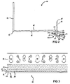
- FIG. 3 shows a top view of a side of the profile strip 10 facing away from a building wall of the building wall when the profile strip 10 is attached.
- the fastening web 14 with openings 16, 17 can be seen, and it becomes clear that these openings 16, 17 are located on attachment the profile strip 10 are readily accessible to a building wall with a tool from the outside, in particular not be covered by the edge web 18.
- profile strip 10 Preferably, all, but at least some of said areas of the profile strip 10, that is supporting web 11, fastening web 14, edge web 18 and plaster web 22, integrally formed.
- profile strip 10 aluminum into consideration, which is in particular an extruded aluminum profile.
- the profile strip 10 may also consist of plastic.
- the base for the cover plates is first mounted on the building wall.
- a profile strip 10 is attached, then this profile strip 10 via inserted into the groove 26 Ver StruktursstMail another profile strip connected to the first profile strip 10 and also attached to the building wall.
- Ver Struktursst another profile strip connected to the first profile strip 10 and also attached to the building wall.
- the cover plates are pushed into the moldings 10, between the mounting bar 14 and edge web 18, and attached all the wide cover plates.
- the cover layer is covered with a mesh fabric, which is fixed with a spatula adhesive to the cover plates and the profile strip.
- the spatula adhesive layer forms a flush layer, which has a thickness of about 1.0 mm to 1.5 mm, for example.
- the advantageous anchoring and adhesion to the profile strip results from the above statements.
- the trimming of the mesh fabric takes place at one of the cut-off edges 28 of the groove, preferably at the outer cut-off edge, that is to say at the cut-off edge formed on the projection 25 of the plaster ridge 22.
- Over the mesh fabric plaster is then applied.
- the plaster layer is formed by peeling off at the Abziehkante 30, for example, it has a thickness between 1.0 mm and 4.0 mm, in particular of about 2.0 mm.
- the advantageous anchoring and adhesion of the plaster layer on the profile strip 10 also results from the above statements.
- the knock anchor 35 includes a dowel main body 40 and a protective crown 41.
- the dowel main body 40 has an inner cavity 42 which is intended to receive the nail shank 37.
- the protective crown 41 is adapted in shape and dimensions of the nail head 38 so that the protective crown 41 in the hammered state of the nail 36 receives the nail head 38 and thereby prevents direct contact between nail 36 and profile strip 10.
- the direction of impact of the nail 36 in the knock anchor 35 is shown in FIG 4 by the arrows 43.
- a direct electrical contact between the usually made of aluminum profile strip 10 and the usually steel, in particular galvanized steel, existing nail 36 would cause electrical reactions that lead to material damage.
- the impact anchor 35 ensures a spacing of the profile strip 10 and nail 36.
- the impact anchor 35 is made of plastic, for example Nylon®, thereby preventing electrical contact between the profile strip 10 and nail 36. Electrochemical reactions between aluminum and galvanized Steel can not occur.
Landscapes
- Engineering & Computer Science (AREA)
- Architecture (AREA)
- Civil Engineering (AREA)
- Structural Engineering (AREA)
- Finishing Walls (AREA)
Priority Applications (1)
| Application Number | Priority Date | Filing Date | Title |
|---|---|---|---|
| EP04022144A EP1637664A1 (fr) | 2004-09-17 | 2004-09-17 | Profil de base pour panneaux de revêtement de murs de bâtiments, et procédé de fixation associé. |
Applications Claiming Priority (1)
| Application Number | Priority Date | Filing Date | Title |
|---|---|---|---|
| EP04022144A EP1637664A1 (fr) | 2004-09-17 | 2004-09-17 | Profil de base pour panneaux de revêtement de murs de bâtiments, et procédé de fixation associé. |
Publications (1)
| Publication Number | Publication Date |
|---|---|
| EP1637664A1 true EP1637664A1 (fr) | 2006-03-22 |
Family
ID=34926578
Family Applications (1)
| Application Number | Title | Priority Date | Filing Date |
|---|---|---|---|
| EP04022144A Withdrawn EP1637664A1 (fr) | 2004-09-17 | 2004-09-17 | Profil de base pour panneaux de revêtement de murs de bâtiments, et procédé de fixation associé. |
Country Status (1)
| Country | Link |
|---|---|
| EP (1) | EP1637664A1 (fr) |
Cited By (3)
| Publication number | Priority date | Publication date | Assignee | Title |
|---|---|---|---|---|
| EP1952969A2 (fr) | 2007-01-24 | 2008-08-06 | Konrad Lehrhuber | Profilé de construction en plastique avec structure d'ancrage en surface pour enduit et couleur |
| DE202011103831U1 (de) | 2011-07-29 | 2011-09-07 | Richard Malcher | Profilleiste |
| DE102021101961A1 (de) | 2021-01-28 | 2022-07-28 | Protektorwerk Florenz Maisch Gmbh & Co. Kg | Putzprofil |
Citations (4)
| Publication number | Priority date | Publication date | Assignee | Title |
|---|---|---|---|---|
| US5003743A (en) * | 1990-03-30 | 1991-04-02 | Vinyl Corporation | Panel support member and support arrangement |
| EP1001103A2 (fr) * | 1998-11-11 | 2000-05-17 | Lorentz, Doris | Profilé de bordure pour revêtement de mur |
| DE20109726U1 (de) * | 2000-06-16 | 2001-09-20 | MAGE GEHRING Ges.m.b.H., Völkermarkt-Haimburg | Aufsteckprofilleiste |
| US6470638B1 (en) * | 2000-08-24 | 2002-10-29 | Plastics Components, Inc. | Moisture management system |
-
2004
- 2004-09-17 EP EP04022144A patent/EP1637664A1/fr not_active Withdrawn
Patent Citations (4)
| Publication number | Priority date | Publication date | Assignee | Title |
|---|---|---|---|---|
| US5003743A (en) * | 1990-03-30 | 1991-04-02 | Vinyl Corporation | Panel support member and support arrangement |
| EP1001103A2 (fr) * | 1998-11-11 | 2000-05-17 | Lorentz, Doris | Profilé de bordure pour revêtement de mur |
| DE20109726U1 (de) * | 2000-06-16 | 2001-09-20 | MAGE GEHRING Ges.m.b.H., Völkermarkt-Haimburg | Aufsteckprofilleiste |
| US6470638B1 (en) * | 2000-08-24 | 2002-10-29 | Plastics Components, Inc. | Moisture management system |
Cited By (4)
| Publication number | Priority date | Publication date | Assignee | Title |
|---|---|---|---|---|
| EP1952969A2 (fr) | 2007-01-24 | 2008-08-06 | Konrad Lehrhuber | Profilé de construction en plastique avec structure d'ancrage en surface pour enduit et couleur |
| DE102007003511A1 (de) | 2007-01-24 | 2008-08-14 | Konrad Lehrhuber | Bauprofilleiste aus Kunststoff mit einer Oberflächenverankerungsstruktur für Putz |
| DE202011103831U1 (de) | 2011-07-29 | 2011-09-07 | Richard Malcher | Profilleiste |
| DE102021101961A1 (de) | 2021-01-28 | 2022-07-28 | Protektorwerk Florenz Maisch Gmbh & Co. Kg | Putzprofil |
Similar Documents
| Publication | Publication Date | Title |
|---|---|---|
| DE69433730T2 (de) | Befestigung einer Wandverkleidung | |
| DE2310333A1 (de) | Wandanordnung bestehend aus einem inneren wandteil und einem aeusseren wandteil, die mit abstand voneinander angeordnet sind | |
| EP1857606B1 (fr) | Structure d'isolation thermique à un mur de bâtiment avec une baguette pour plâtre | |
| EP2096229B1 (fr) | Espaceur pour système d'enduit épais | |
| AT504027B1 (de) | Putzanschlussleiste für fensterrahmen, türrahmen oder dergleichen | |
| EP1426520B1 (fr) | Combinaison d'une plaque ou d'un panneau avec au moins un dispositif de fixation et procédé pour la fixation d'une plaque ou d'un panneau | |
| DE102011102968A1 (de) | Haltevorrichtung und Verfahren zur Montage einer solchen | |
| EP1637664A1 (fr) | Profil de base pour panneaux de revêtement de murs de bâtiments, et procédé de fixation associé. | |
| EP1477621B1 (fr) | Ensemble de pièces pour construire le raccordement entre l'isolation thermique extérieure et l'isolation thermique de socle d'un bâtiment | |
| DE9005635U1 (de) | Haftsicherungsanker für Dämmplatten, insbesondere solchen aus Mineralwolle | |
| AT507318B1 (de) | Sockelprofilleiste für dämmplatten | |
| EP2770134B1 (fr) | Système de profilé pour une façade de bâtiment | |
| DE19704715C2 (de) | Wärmedämmplatte aus Kunstschaumstoff sowie Verfahren zum Verlegen und Befestigen von Wärmedämmplatten | |
| DE29919360U1 (de) | Befestigungselement für ein Wärmedämmelement an einer Gebäudewand | |
| DE10237076A1 (de) | Plattenverband aus Platten aus einem Gipswerkstoff und Verfahren zum Herstellen eines Plattenverbandes | |
| DE102007048802A1 (de) | Befestigungselement | |
| EP0629754A2 (fr) | Revêtement de murs | |
| DE19747602A1 (de) | Kantenschutz-Richtwinkel | |
| DE102016118491A1 (de) | Verfahren zur Montage von Isolierplatten an einer Gebäudewand und Satz von Elementen zur Montage von Isolierplatten an einer Gebäudewand | |
| DE102004059531B4 (de) | Dämmung für eine Gebäudewand | |
| EP3257413B1 (fr) | Partie fonctionnelle et/ou décorative à insérer dans une zone cornière ou dans une niche, par exemple d'au moins un espace en partie carrelé | |
| AT518375B1 (de) | Verfahren zur Herstellung eines Bauelements aus Polystyrol | |
| DE10229115A1 (de) | Zweischaliges Mauerwerk und Verbindungselement dafür | |
| EP2742195B1 (fr) | Procédé de montage sans vis d'une baguette de finition | |
| EP4036347B1 (fr) | Profilé d'enduit avec une feuille d'enduit sur l'un de ses pieds d'enduit |
Legal Events
| Date | Code | Title | Description |
|---|---|---|---|
| PUAI | Public reference made under article 153(3) epc to a published international application that has entered the european phase |
Free format text: ORIGINAL CODE: 0009012 |
|
| AK | Designated contracting states |
Kind code of ref document: A1 Designated state(s): AT BE BG CH CY CZ DE DK EE ES FI FR GB GR HU IE IT LI LU MC NL PL PT RO SE SI SK TR |
|
| AX | Request for extension of the european patent |
Extension state: AL HR LT LV MK |
|
| 17P | Request for examination filed |
Effective date: 20060824 |
|
| AKX | Designation fees paid |
Designated state(s): AT CZ DE |
|
| 17Q | First examination report despatched |
Effective date: 20061121 |
|
| GRAP | Despatch of communication of intention to grant a patent |
Free format text: ORIGINAL CODE: EPIDOSNIGR1 |
|
| STAA | Information on the status of an ep patent application or granted ep patent |
Free format text: STATUS: THE APPLICATION IS DEEMED TO BE WITHDRAWN |
|
| 18D | Application deemed to be withdrawn |
Effective date: 20081023 |