EP1632626B1 - Serrure pour véhicule automobile - Google Patents
Serrure pour véhicule automobile Download PDFInfo
- Publication number
- EP1632626B1 EP1632626B1 EP20050017653 EP05017653A EP1632626B1 EP 1632626 B1 EP1632626 B1 EP 1632626B1 EP 20050017653 EP20050017653 EP 20050017653 EP 05017653 A EP05017653 A EP 05017653A EP 1632626 B1 EP1632626 B1 EP 1632626B1
- Authority
- EP
- European Patent Office
- Prior art keywords
- pawl
- motor vehicle
- storage element
- latch
- vehicle lock
- Prior art date
- Legal status (The legal status is an assumption and is not a legal conclusion. Google has not performed a legal analysis and makes no representation as to the accuracy of the status listed.)
- Not-in-force
Links
Images


Classifications
-
- E—FIXED CONSTRUCTIONS
- E05—LOCKS; KEYS; WINDOW OR DOOR FITTINGS; SAFES
- E05B—LOCKS; ACCESSORIES THEREFOR; HANDCUFFS
- E05B85/00—Details of vehicle locks not provided for in groups E05B77/00 - E05B83/00
- E05B85/01—Mechanical arrangements specially adapted for hands-free locking or unlocking
-
- E—FIXED CONSTRUCTIONS
- E05—LOCKS; KEYS; WINDOW OR DOOR FITTINGS; SAFES
- E05B—LOCKS; ACCESSORIES THEREFOR; HANDCUFFS
- E05B49/00—Electric permutation locks; Circuits therefor ; Mechanical aspects of electronic locks; Mechanical keys therefor
-
- E—FIXED CONSTRUCTIONS
- E05—LOCKS; KEYS; WINDOW OR DOOR FITTINGS; SAFES
- E05B—LOCKS; ACCESSORIES THEREFOR; HANDCUFFS
- E05B81/00—Power-actuated vehicle locks
- E05B81/12—Power-actuated vehicle locks characterised by the function or purpose of the powered actuators
- E05B81/14—Power-actuated vehicle locks characterised by the function or purpose of the powered actuators operating on bolt detents, e.g. for unlatching the bolt
- E05B81/15—Power-actuated vehicle locks characterised by the function or purpose of the powered actuators operating on bolt detents, e.g. for unlatching the bolt with means preventing the detent to return to its latching position before the bolt has moved to the unlatched position
-
- Y—GENERAL TAGGING OF NEW TECHNOLOGICAL DEVELOPMENTS; GENERAL TAGGING OF CROSS-SECTIONAL TECHNOLOGIES SPANNING OVER SEVERAL SECTIONS OF THE IPC; TECHNICAL SUBJECTS COVERED BY FORMER USPC CROSS-REFERENCE ART COLLECTIONS [XRACs] AND DIGESTS
- Y10—TECHNICAL SUBJECTS COVERED BY FORMER USPC
- Y10T—TECHNICAL SUBJECTS COVERED BY FORMER US CLASSIFICATION
- Y10T292/00—Closure fasteners
- Y10T292/08—Bolts
- Y10T292/1043—Swinging
- Y10T292/1044—Multiple head
- Y10T292/1045—Operating means
- Y10T292/1047—Closure
-
- Y—GENERAL TAGGING OF NEW TECHNOLOGICAL DEVELOPMENTS; GENERAL TAGGING OF CROSS-SECTIONAL TECHNOLOGIES SPANNING OVER SEVERAL SECTIONS OF THE IPC; TECHNICAL SUBJECTS COVERED BY FORMER USPC CROSS-REFERENCE ART COLLECTIONS [XRACs] AND DIGESTS
- Y10—TECHNICAL SUBJECTS COVERED BY FORMER USPC
- Y10T—TECHNICAL SUBJECTS COVERED BY FORMER US CLASSIFICATION
- Y10T292/00—Closure fasteners
- Y10T292/08—Bolts
- Y10T292/1043—Swinging
- Y10T292/1075—Operating means
- Y10T292/1082—Motor
Definitions
- the present invention relates to a motor vehicle lock according to the preamble of claim 1.
- motor vehicle lock according to the preamble of claim 1.
- all types of door, hood or flap locks are summarized under the term motor vehicle lock.
- Today motor vehicle locks usually have the closing elements lock latch and pawl, wherein the latch is in the closed vehicle door with a fastened to the vehicle body striker engaged.
- the latch can be held by the pawl located in its sunken position in a main latching position and in any pre-engaged position.
- the latch has a main catch and possibly a pre-rest, which can be brought into engagement with an arranged on the pawl locking lug.
- the latch By lifting the pawl, the latch is released in the direction of its open position.
- the latch are usually biased in its open position and the pawl in its sunken position.
- a motor vehicle lock with a memory function ( DE 195 20 359 A1 ).
- the memory function ensures that the Pawl during the opening process in any case as long as it remains in its raised position until the pre-rest of the latch has passed the locking lug of the pawl.
- the motor vehicle lock on a lever-shaped storage element, which is also commonly called "snow load lever".
- the storage element falls from an excavated to a sunken position and holds the pawl so in its raised position.
- the latch in the open position displaces the storage element in its raised position, so that the pawl is finally released by the positive coupling between latch and storage element.
- the known motor vehicle lock in this case has an opening drive, through which the pawl is motorized liftable.
- a similar conception shows the motor vehicle lock ( DE 196 17 428 A1 ), from which the present invention proceeds.
- a lever-shaped designed memory element is provided which is associated with the pawl and holds this as described above in the raised position.
- an opening drive is provided which interacts on the one hand with the pawl and on the other hand with the storage element.
- a Vorrastunterd Wegungssystem is provided, which plays no role in this context.
- EP 0 978 610 B1 a motor vehicle lock with memory function is known ( EP 0 978 610 B1 ), which has an elastic, lever-shaped memory element which is rigidly coupled to the pawl.
- the storage element When lifting the pawl, the storage element snaps into engagement with the latch and thus holds the pawl in the raised position.
- this snap connection dissolves and the pawl is released.
- the memory function described above not only leads to an increase in the comfort of use, but may be indispensable for the operability of the motor vehicle lock in certain cases.
- An example of this is another known motor vehicle lock ( DE 102 34 782 A1 ), which is equipped with an opening drive. During the opening process, the opening drive initially adjusts the pawl in the excavated position and then runs in front of block to a arranged on the pawl stop. The stop is located only when the pawl excavated in the trajectory of the opening drive. It is here to ensure that the pawl remains excavated until the blocking of the opening drive, which equals the memory function described above.
- the pawl In all motor vehicle locks described the pawl is held in the storage state of the storage element in its raised position until the latch has reached its open position. The pawl thus remains in the excavated position even if the vehicle door can not open, for example, due to the icing. If the disability described later unexpectedly falls away, for example, by the melting of the ice while driving, the vehicle door will open accordingly unexpectedly. This system behavior is associated with a considerable accident risk.
- the present invention is based on the problem, the known motor vehicle lock with memory function to design and further develop that its reliability is increased.
- the pawl from the memory state is motor-releasable.
- the release of the pawl is always possible at any time, so that an unwanted whereabouts of the pawl in the storage state can be easily prevented.
- the motor release of the pawl can be provided in addition to the above-described positive coupling, which basically causes the release of the pawl in the adjustment of the latch in its open position.
- the release of the pawl from the memory state is provided exclusively by motor. This then leads to a particularly simple structural design.
- the motor release of the pawl can be controlled by means of the control device of the motor vehicle lock at a predetermined control time. For example, it may be provided that the motor release takes place at each control time, or even that the control of other boundary conditions, for example, the position of the latch is made dependent.
- the preferred embodiment according to claim 6 shows the multiple use of the opening drive on the one hand for the motorized lifting of the pawl and on the other hand for the motor release of the pawl from the memory state. This makes a particularly compact design achievable.
- the motor vehicle lock shown in Fig. 1 is equipped with the closing elements latch 1 and pawl 2, wherein the latch 1 in an open position, not shown, can be brought into the illustrated in Figs. 1 and 2 main latching position and in the pre-latching position, not shown.
- the latch 1 is preferably in the direction of its open position, in Fig. 1 to the left, biased.
- the latch 1 has a main catch 3 and a pre-rest 4.
- the pawl 2 can be brought into a position shown in Fig. 1 sunken position and in an illustrated in Fig. 2 excavated position. It can be seen Fig. 1 that the pawl 2 located in its sunken position holds the latch 1 in the main position (Fig. 1) and in the pre-locking position and that the befmdliche in its raised position pawl 2 the latch 1 in the direction of its open position releases (Fig. 2).
- the pawl 2 is associated with a memory element 5, which holds the pawl 2 after its lifting in the raised position, which corresponds to the already-mentioned memory state.
- This memory state is shown in FIG.
- the pawl 2 can be lifted by a motor, wherein the lifting operation takes place in block mode.
- the lifting operation takes place in block mode.
- the pawl 2 In its raised position of the pawl 2 has a corresponding blocking effect, so that it must be ensured that the pawl 2 remains long enough in its raised position. This is ensured here by the storage element 5.
- the memory state is held until a further functional state of the motor vehicle lock is reached.
- the further functional state is in any case achieved when the latch 1 has reached its open position. This is preferably ensured by a corresponding positive coupling between the latch 1 and the memory element 5, as will be shown below.
- Such a further functional state can additionally be defined in another way, such as by a specific control state, as will also be shown.
- the motor vehicle lock has a control device 6 which is arranged either in the motor vehicle lock itself or separately in the motor vehicle.
- the control device 6 is indicated only schematically in the drawing.
- the pawl 2 is motor-releasable out of the memory state shown in Fig. 2 and then, freely from the memory element 5, in the direction of its sunken position is adjustable.
- the pawl 2 is preferably biased in the direction of its retracted position so that it snaps to a certain extent in the direction of its retracted position after release.
- the motor release of the pawl 2 can be controlled by means of the control device 6 at a predetermined control time.
- the control time can be defined as the end of a predetermined period of time, which begins with the lifting of the pawl 2. Then, the motor release of the pawl 2 is basically, for example, a few seconds after the release of the pawl second
- control time is defined as the time after the lifting of the pawl 2 timing of a signal transmission from the rest of the vehicle electrical system to the control device 6 of the motor vehicle lock.
- This signal transmission can take place, for example, when switching on the ignition or when starting the motor vehicle.
- the control of the motor release of the pawl 2 basically in each control time, ie after each lifting of the pawl 2, takes place.
- the activation of the motor release of the pawl 2 takes place selectively in the sense that a corresponding control is not performed in each control time.
- the control device 6 is assigned a lock trap monitoring 7 with respect to the position of the latch 1.
- the lock trap monitoring 7 a simple push-button 8, which reports the pivoting of the latch 1 in the open position to the control device 6.
- a particularly effective mode of operation is now achieved in that the control device 6, when the lock catch 1 between the time of lifting the pawl 2 and the control time has not yet fully reached their open position, the motor release of the pawl 2 from the memory state drives out. This is the error state described above, namely, when the adjustment of the lock latch 1 in the direction of its open position, for example by icing, is hindered.
- the lock trap monitoring 7 does not necessarily have to take place directly on the latch 1.
- the opening of the vehicle door indirectly provide information about the adjustment of the latch 1 in its open position. This is advantageous in that the vehicle door is usually designed anyway with an AJAR switch.
- a pawl monitoring 7a is provided with regard to the position of the pawl 2, which in turn can be queried by the control device 6.
- the pawl monitoring 7a also has a simple push-button switch 8a which controls the pivoting of the pawl 2 in the excavated position to the controller 6 reports.
- the pawl 2 at the time of control which is so preferably the time of lifting the pawl 2 downstream, unchanged in its excavated position, so the above error condition is present and the control device 6 controls the motor release of the pawl 2.
- a particularly reliable monitoring result is achieved by the additional query of the above-mentioned lock trap monitoring 7.
- the motor release of the pawl 2 is particularly advantageous in connection with the above-mentioned forced coupling between latch 1 and memory element 5.
- This forced coupling causes an adjustment of the lock latch 1 in the open position, in principle, a release of the pawl 2 from the memory state.
- the positive coupling on the one hand and the motor release of the pawl 2 on the other hand then represent complementary measures.
- the adjustment of the latch 1 is hindered after lifting the pawl 2 in the open position, the positive coupling between latch 1 and memory element 5 does not come to bear, which in turn remains the pawl 2 in its raised position.
- motor release of the pawl 2 is then avoided that after the elimination of disability, so for example, after the melting of the ice in previously icy vehicle door, an unexpected opening of the vehicle door.
- the pawl 2 falls after their release advantageously back into the main catch 3 or at least in the path of movement of the latch 4 of the latch 1, as far as the latch 1 is not already largely adjusted in the direction of its open position.
- a storage drive 9 is presently provided, which can advantageously be designed as an additional drive depending on the application.
- an already existing drive is used as a storage drive 9.
- the motor vehicle lock has an opening drive 10 for motorized lifting of the pawl 2, which simultaneously assumes the function of the storage drive 9.
- a central locking drive or a closing auxiliary drive can also serve for such a double use.
- the opening drive 10 has an actuating element 12 driven by a motor 11.
- the actuating element 12 has a control contour 13 which can be brought into engagement with a driver 14 on the pawl 2.
- the actuator 12 is rotated out of the position shown in Fig. 1 out to the right until the control contour 13 engages with the driver 14 and the pawl 2 pivots to the left.
- the storage element 5 can be brought into a lowered position (FIG. 2), in which the storage element 5 holds the pawl 2 in its raised position.
- the storage element 5 can also be brought into an excavated position (FIG. 1), in which the storage element 5 releases the pawl 2.
- the lifting of the pawl 2 by the opening drive 10 basically causes the adjustment of the memory element 5 in its sunken position (Fig. 2).
- the carrier 14 is moved into the path of movement of a stop 15 arranged on the adjusting element 12. Characterized in that the storage element 5 holds the pawl 2 in this position, the block operation for the opening drive 10 is ensured simultaneously.
- the storage element 5 is designed as a pivotable lever arrangement. In principle, however, the storage element 5 can also be designed as a linearly movable slide or the like.
- the memory element 5 has a stop 16 which can be brought into engagement with a counter stop 17 arranged on the pawl 2. Furthermore, the storage element 5 has a control arm 18, the pivoting thereof, in FIG. 1 to the right, causes the adjustment of the storage element 5 in the excavated position.
- Fig. 2 can be seen that the control arm 18 is located in the memory state in the path of movement of the actuator 12 arranged stop 15.
- the control contour 13 with its partial contour 13a passes through the driver 14 and presses the pawl 2 briefly into an overstroke position.
- the partial contour 13a is equipped with a corresponding slope.
- the stopper 15 comes into engagement with the control arm 18 and thus adjusts the memory element 5 to the right in its excavated position.
- the pawl 2 is released and now snaps in the direction of its sunken position, in Fig. 2 to the right.
- a stop 19 on the pawl 2 finally comes into the path of movement of a contact edge 20 of the control contour 13 and blocks the further movement of the opening drive 10, so that the motor release of the pawl 2 is ensured in block mode.
- the pawl 2 is pivoted in the direction of its sunken position and the arranged on the actuator 12 stop 15 has come out of engagement with the memory element 5, the memory element 5 falls with a contact edge 21 a corresponding abutment edge 22 of the pawl 2.
- the storage element 5 is held in its raised position until the pawl 2 is dug again through the opening drive 10.
- the control arm 18 of the storage element 5 is in befindlichem in the excavated position storage element 5 out of engagement with the storage drive 9, here with the opening drive 10.
- the double use of the opening drive 10 can be realized in the manner described above without major design effort.
- the storage element 5 is equipped with a further control arm 23, with which a control contour 24 on the latch 1 in the storage state in their adjustment in their open position into engagement and the resulting pivoting, in Fig. 2 right around, leads to a lifting of the storage element 5 - forced coupling -.
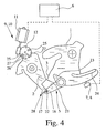
- FIGS. 3 and 4 A further preferred variant of a motor vehicle lock with the above-described memory function is shown in FIGS. 3 and 4. Corresponding components are provided in all figures with the same speedsziffem.
- the motor vehicle lock shown in Figs. 3 and 4 also has the closing elements latch 1 and pawl 2, which cooperate in the manner described above.
- the latch 1 here has only one main catch 3 and no pre-rest.
- Fig. 3 shows the latch 1 in the main latching position when the pawl 2.
- Fig. 4 shows the pawl 2 in its raised position.
- the pawl 2 is held there by a storage element 5.
- the latch 1 is unchanged in its main latching position, but is free of the pawl second
- the storage element 5 is designed as a pivotable lever arrangement.
- the latch 1 comes in their adjustment from the position shown in Fig. 4 right around in its open position into engagement with the control arm 23 and pivots it in Fig. 4 on the left, which in turn corresponds to the above-mentioned positive coupling. This leads to an adjustment of the storage element 5 in the excavated position.
- the latch 1 has a control contour 24.
- a motor release of the pawl 2 is also provided here.
- a storage drive 9 is provided, which may be configured as an additional drive or is an already existing drive.
- an opening drive 10 is again provided, which is the storage drive 9 at the same time.
- the opening drive 10 has a motor 11 and an actuator 12, which is equipped with two pins 25.
- the pawl 2 has a recess 26 and stop surfaces 27, which allow an adjustment of the pawl 2 in the direction of arrival and in Ausheberaum. At the same time a block operation can be realized by the stop surfaces.
- the storage element 5 is now an at least partially preferably made of plastic lever assembly that buckles in the storage state (Fig. 4) under the above increased force, bends away or otherwise causes the release of the pawl.
- the pawl 2 has an engagement member 28 for engagement with the storage element 5 and that the engagement member 28 is preferably made of plastic and buckles in the storage state under the above increased force, bends away or otherwise the release of the pawl 2 causes.
- the above deformation may be an elastic deformation or a non-elastic deformation.
- the deformable component is interpreted as meaning that the pawl 2 can be kept in its excavated position by the storage element 5 in normal operation and that only when the motor release the pawl 2, so under increased force, a corresponding, the pawl 2 releasing deformation takes place.
- the motor release of the pawl 2 from the memory state so the motorized adjustment of the pawl 2 under increased force in the direction of its sunken position. Due to the increased force effect, the memory element 5 and / or the pawl 2 deformed at least partially, which finally causes the release of the pawl 2.
- the deformability of the memory element 5 on the one hand and / or the pawl 2 on the other hand can be supported by a special shaping of these components.
- An example of this is that the memory element 5 and / or the pawl 2 in any case in sections has a substantially arcuate and thus yielding shape.
- the storage lever 5 as a whole has a curved shape, which helps the storage lever 5 together with its material parameters to the desired flexibility.
Claims (12)
- Serrure pour véhicule automobile comprenant les éléments de fermeture loquet (1) et cliquet d'arrêt (2), le loquet (1) pouvant être amené dans une position d'ouverture, une position d'enclenchement principale et éventuellement une position de pré-enclenchement et le cliquet d'arrêt (2) pouvant être amené dans une position engagée et dans une position soulevée, le cliquet d'arrêt (2) qui se trouve dans sa position engagée maintenant le loquet (1) dans sa position d'enclenchement principale et dans la position de pré-enclenchement éventuellement présente et le cliquet d'arrêt (2) qui se trouve dans sa position soulevée libérant le loquet (1) en direction de sa position d'ouverture, un élément accumulateur (5) étant associé au cliquet d'arrêt (2), lequel maintient le cliquet d'arrêt (2) en position soulevée après son soulèvement - état d'accumulation - jusqu'à ce qu'un autre état fonctionnel de la serrure pour véhicule automobile ait été atteint, notamment jusqu'à ce que le loquet (1) ait atteint sa position d'ouverture, et comprenant un dispositif de commande (6) dans la serrure pour véhicule automobile ou séparément de celle-ci dans le véhicule automobile par le biais duquel peuvent être commandées les fonctions individuelles de la serrure pour véhicule automobile, caractérisée en ce que le cliquet d'arrêt (2) peut être libéré de manière motorisée depuis l'état d'accumulation et être ensuite amené sans entraves par l'élément d'accumulation (5) en direction de sa position engagée et que la libération motorisée du cliquet d'arrêt (2) peut être commandée à un moment de commande prédéfini au moyen du dispositif de commande (6).
- Serrure pour véhicule automobile selon la revendication 1, caractérisée en ce que le moment de commande est défini comme étant la fin d'un intervalle de temps prédéfini qui commence par le soulèvement du cliquet d'arrêt (2).
- Serrure pour véhicule automobile selon la revendication 1 ou 2, caractérisée en ce que le moment de commande est défini comme étant le moment situé après le soulèvement du cliquet d'arrêt (2) de la transmission d'un signal depuis le reste du système électrique du véhicule vers le dispositif de commande (6) de la serrure pour véhicule automobile, de préférence que cette transmission de signal s'effectue au moment de mettre le contact ou lors du démarrage du véhicule.
- Serrure pour véhicule automobile selon l'une des revendications précédentes, caractérisée en ce qu'une surveillance du loquet (7) concernant la position du loquet (1) et/ou une surveillance du cliquet d'arrêt (7a) concernant la position du cliquet d'arrêt (2) est associée au dispositif de commande (6) et que le dispositif de commande (6), au moment de commande, commande la libération motorisée du cliquet d'arrêt (2) en fonction de la surveillance du loquet (7) et/ou de la surveillance du cliquet d'arrêt (7a), de préférence que le dispositif de commande (6) commande la libération motorisée du cliquet d'arrêt (2) lorsque le loquet (1) n'a pas encore complètement atteint sa position d'ouverture depuis le soulèvement du cliquet d'arrêt (2) jusqu'au moment de commande ou que le dispositif de commande (6) commande la libération motorisée du cliquet d'arrêt (2) lorsque le cliquet d'arrêt (2), au moment de commande, se trouve dans la position soulevée et de préférence lorsqu'en même temps le loquet (1) n'a pas encore complètement atteint sa position d'ouverture.
- Serrure pour véhicule automobile selon l'une des revendications précédentes, caractérisée en ce que le loquet (1) est couplé avec l'élément accumulateur (5) de telle sorte qu'un déplacement du loquet (1) en position d'ouverture provoque la libération du cliquet d'arrêt (2) de son état d'accumulation.
- Serrure pour véhicule automobile selon l'une des revendications précédentes, caractérisée en ce qu'un mécanisme d'entraînement à accumulateur (9) est prévu pour la libération motorisée du cliquet d'arrêt (2), de préférence qu'un mécanisme d'entraînement d'ouverture (10) est prévu pour le soulèvement motorisé du cliquet d'arrêt (2) et que le mécanisme d'entraînement d'ouverture (10) est en même temps le mécanisme d'entraînement à accumulateur (9).
- Serrure pour véhicule automobile selon l'une des revendications précédentes, caractérisée en ce que l'élément accumulateur (5) peut être amené dans une position engagée dans laquelle l'élément accumulateur (5) maintient le cliquet d'arrêt (2) dans sa position soulevée et que l'élément accumulateur (5) peut être amené dans une position soulevée dans laquelle l'élément accumulateur (5) libère le cliquet d'arrêt (2), de préférence que l'élément accumulateur (5) est précontraint dans sa position engagée.
- Serrure pour véhicule automobile selon l'une des revendications précédentes, caractérisée en ce que l'élément accumulateur (5) est configuré sous la forme d'un arrangement de levier pivotant.
- Serrure pour véhicule automobile selon les revendications 6 et 8, caractérisée en ce que l'élément accumulateur (5) présente au moins un bras de commande (18) dont le pivotement dans une position de pivotement provoque le déplacement de l'élément accumulateur (5) dans la position soulevée et que le bras de commande (18) est ou peut être amené en prise avec le mécanisme d'entraînement à accumulateur (9) et peut ainsi être pivoté de manière motorisée, de préférence que le bras de commande (18) est en prise avec le mécanisme d'entraînement à accumulateur (9) exclusivement lorsque l'élément accumulateur (5) se trouve en position engagée.
- Serrure pour véhicule automobile selon la revendication 8 et éventuellement selon la revendication 9, caractérisée en ce que l'élément accumulateur (5) présente éventuellement un bras de commande supplémentaire (23) avec lequel le loquet (1) vient en prise à l'état d'accumulation lorsqu'il est déplacé dans sa position d'ouverture et dont le pivotement qui en résulte donne lieu à un soulèvement de l'élément accumulateur (5).
- Serrure pour véhicule automobile selon l'une des revendications précédentes, caractérisée en ce que l'élément accumulateur (5) est un arrangement de levier constitué au moins partiellement de préférence de matière plastique qui, à l'état d'accumulation sous l'effet d'une force accrue, s'infléchit, se plie ou provoque d'une autre manière la libération du cliquet d'arrêt (2) et/ou de préférence que le cliquet d'arrêt (2) présente un élément de prise (28) pour venir en prise avec l'élément accumulateur (5) et que l'élément de prise (28) est de préférence constitué de matière plastique et, à l'état d'accumulation sous l'effet d'une force accrue, s'infléchit, se plie ou provoque d'une autre manière la libération du cliquet d'arrêt (2) et/ou, encore de préférence, que l'élément accumulateur (5) et/ou le cliquet d'arrêt (2) présentent dans tous les cas par portion une forme essentiellement courbée et de ce fait flexible.
- Serrure pour véhicule automobile selon la revendication 11, caractérisée en ce que la libération motorisée du cliquet d'arrêt (2) comprend le déplacement motorisé du cliquet d'arrêt (2) en exerçant une force accrue en direction de sa position engagée, l'élément accumulateur (5) et/ou le cliquet d'arrêt (2) se déformant au moins partiellement, ce qui provoque finalement la libération du cliquet d'arrêt (2).
Applications Claiming Priority (1)
| Application Number | Priority Date | Filing Date | Title |
|---|---|---|---|
| DE200410042966 DE102004042966A1 (de) | 2004-09-02 | 2004-09-02 | Kraftfahrzeugschloß |
Publications (2)
| Publication Number | Publication Date |
|---|---|
| EP1632626A1 EP1632626A1 (fr) | 2006-03-08 |
| EP1632626B1 true EP1632626B1 (fr) | 2007-08-01 |
Family
ID=35453504
Family Applications (1)
| Application Number | Title | Priority Date | Filing Date |
|---|---|---|---|
| EP20050017653 Not-in-force EP1632626B1 (fr) | 2004-09-02 | 2005-08-12 | Serrure pour véhicule automobile |
Country Status (4)
| Country | Link |
|---|---|
| US (1) | US7452013B2 (fr) |
| EP (1) | EP1632626B1 (fr) |
| AT (1) | ATE368787T1 (fr) |
| DE (2) | DE102004042966A1 (fr) |
Families Citing this family (19)
| Publication number | Priority date | Publication date | Assignee | Title |
|---|---|---|---|---|
| DE102006019515A1 (de) * | 2006-04-13 | 2007-10-18 | Rahrbach Gmbh | Mehrstufiger Türverschluss |
| EP2310601B1 (fr) * | 2008-05-26 | 2016-02-24 | Magna Closures SpA | Serrure de véhicule automobile avec cliquet double |
| DE102008028256A1 (de) * | 2008-06-13 | 2009-12-24 | Kiekert Ag | Schließvorrichtung mit zwei Sperrklinken und motorisch angetriebenen Stellantrieb |
| CA2697768A1 (fr) * | 2009-03-25 | 2010-09-25 | Magna Closures Inc. | Verrou de fermeture pour porte de vehicule |
| DE102009034904B4 (de) | 2009-07-27 | 2019-07-11 | Magna BÖCO GmbH | Verriegelungsvorrichtung für eine Fahrzeugtür |
| DE102009037037B4 (de) * | 2009-08-13 | 2018-10-18 | BÖCO Böddecker & Co. GmbH & Co. KG | Verriegelungsvorrichtung für eine Fahrzeugtür |
| DE202009016636U1 (de) † | 2009-12-09 | 2011-04-21 | BROSE SCHLIEßSYSTEME GMBH & CO. KG | Kraftfahrzeugschloss |
| JP5723388B2 (ja) | 2010-02-05 | 2015-05-27 | マグナ クロージャーズ ソシエタ ペル アチオニ | 二重爪構造を備えた車両用ラッチ |
| EP2602184B1 (fr) * | 2011-12-09 | 2018-03-07 | Safran Landing Systems | Boîtier d'accrochage à actionneur de déverrouillage à came cylindrique |
| KR101372022B1 (ko) * | 2012-08-24 | 2014-03-07 | 기아자동차주식회사 | 차량용 2단 가이드 후드 래치 장치 |
| DE102013103245A1 (de) * | 2013-03-28 | 2014-10-02 | Kiekert Aktiengesellschaft | Kraftfahrzeugtürverschluss |
| DE202013103327U1 (de) | 2013-07-24 | 2014-10-27 | BROSE SCHLIEßSYSTEME GMBH & CO. KG | Kraftfahrzeugschloss |
| FR3014472B1 (fr) * | 2013-12-10 | 2017-10-06 | Inteva Products Llc | Ensemble et systeme de verrouillage de portiere |
| DE102016116616A1 (de) | 2016-09-06 | 2018-03-08 | Kiekert Ag | Kraftfahrzeugtürschloss |
| DE102017121319A1 (de) * | 2017-09-14 | 2019-03-14 | Huf Hülsbeck & Fürst Gmbh & Co. Kg | Schlossanordnung eines Kraftfahrzeugs |
| DE102017124519A1 (de) * | 2017-10-20 | 2019-04-25 | Kiekert Ag | Kraftfahrzeugtürschloss |
| DE102018101142A1 (de) * | 2018-01-19 | 2019-07-25 | Kiekert Ag | Kraftfahrzeugtürschloss |
| DE102018120435A1 (de) * | 2018-08-22 | 2020-02-27 | Kiekert Ag | Kraftfahrzeug-Schloss |
| DE102021111341A1 (de) | 2021-05-03 | 2022-11-03 | Kiekert Aktiengesellschaft | Kraftfahrzeug-Schloss |
Family Cites Families (16)
| Publication number | Priority date | Publication date | Assignee | Title |
|---|---|---|---|---|
| DE19520359A1 (de) | 1995-06-07 | 1996-12-12 | Bocklenberg & Motte Bomoro | Kraftfahrzeug-Hauben- oder Türverschluß |
| US5613716A (en) * | 1996-01-25 | 1997-03-25 | General Motors Corporation | Electronic vehicle door unlatch control |
| DE19614122B4 (de) * | 1996-04-11 | 2006-04-27 | Brose Schließsysteme GmbH & Co.KG | Kraftfahrzeug-Klappenschloß oder -Türschloß |
| DE19617428C2 (de) * | 1996-05-01 | 1998-06-10 | Kiekert Ag | Kraftfahrzeug-Türverschluß mit elektrischem Türschloß und elektrische Zuziehhilfe für die zugeordnete Kraftfahrzeugtür |
| EP0808977B1 (fr) * | 1996-05-21 | 2000-08-16 | Robert Bosch Gmbh | Méthode pour le contrôle d'une serrure pour portière de véhicule automobile actionnée de façon électrique |
| DE19632915A1 (de) * | 1996-05-21 | 1997-11-27 | Bosch Gmbh Robert | Verfahren zur Ansteuerung eines elektrisch betätigten Kraftfahrzeug-Türschlosses o. dgl. |
| US6422615B1 (en) * | 1998-07-20 | 2002-07-23 | Mannesmann Vdo Ag | Closure device with shutting aid |
| FR2782111B1 (fr) | 1998-08-05 | 2002-12-06 | Valeo Securite Habitacle | Serrure electrique perfectionnee pour ouvrant de vehicule automobile |
| DE10019668A1 (de) * | 2000-04-19 | 2001-10-31 | Hs Products Karosseriesysteme | Schließvorrichtung, insbesondere für eine Kofferraumklappe |
| GB0011991D0 (en) * | 2000-05-19 | 2000-07-05 | Meritor Light Vehicle Sys Ltd | Latch assembly and vehicle including such a latch assembly |
| JP3902908B2 (ja) * | 2000-07-07 | 2007-04-11 | 株式会社大井製作所 | 自動車用トランクリッドロックの駆動装置 |
| US20020167175A1 (en) * | 2001-01-30 | 2002-11-14 | Robert Bosch Gmbh | Motor vehicle gate lock arrangement |
| US6565132B2 (en) * | 2001-06-28 | 2003-05-20 | Delphi Technologies, Inc. | Vehicle compartment latch |
| AU2002347172A1 (en) * | 2001-12-12 | 2003-07-09 | Intier Automotive Closures Inc. | Snow load lever with two part pawl lever construction |
| DE10234782A1 (de) | 2002-07-30 | 2004-02-19 | Brose Schließsysteme GmbH & Co.KG | Kraftfahrzeugschloß |
| EP1457625A3 (fr) * | 2003-03-08 | 2008-08-27 | Brose Schliesssysteme GmbH & Co. KG | Serrure pour véhicule à ouverture assistée électriquement |
-
2004
- 2004-09-02 DE DE200410042966 patent/DE102004042966A1/de not_active Withdrawn
-
2005
- 2005-08-12 EP EP20050017653 patent/EP1632626B1/fr not_active Not-in-force
- 2005-08-12 AT AT05017653T patent/ATE368787T1/de not_active IP Right Cessation
- 2005-08-12 DE DE200550001128 patent/DE502005001128D1/de active Active
- 2005-09-02 US US11/217,674 patent/US7452013B2/en not_active Expired - Fee Related
Also Published As
| Publication number | Publication date |
|---|---|
| DE502005001128D1 (de) | 2007-09-13 |
| DE102004042966A1 (de) | 2006-03-09 |
| ATE368787T1 (de) | 2007-08-15 |
| US20060076784A1 (en) | 2006-04-13 |
| EP1632626A1 (fr) | 2006-03-08 |
| US7452013B2 (en) | 2008-11-18 |
Similar Documents
| Publication | Publication Date | Title |
|---|---|---|
| EP1632626B1 (fr) | Serrure pour véhicule automobile | |
| DE19614122B4 (de) | Kraftfahrzeug-Klappenschloß oder -Türschloß | |
| DE19906997C2 (de) | Kraftfahrzeug-Türschloß, -Haubenschloß oder -Klappenschloß | |
| EP2909404B1 (fr) | Serrure de portière de véhicule automobile | |
| DE102008018500A1 (de) | Kraftfahrzeugschloß | |
| DE202013104118U1 (de) | Kraftfahrzeugschloss | |
| EP1485558A1 (fr) | Serrure, en particulier pour portes de vehicule, battants ou analogues | |
| DE102016011162A1 (de) | Verriegelungsvorrichtung für eine Fahrzeugtür und Verfahren | |
| EP1045093B1 (fr) | Serrure pour une porte d'automobile ou similaire | |
| DE3203702A1 (de) | Betaetigungsvorrichtung fuer ein automatisches kraftfahrzeug-getriebe | |
| DE102019134659A1 (de) | Intelligente verriegelungsvorrichtung mit doppelklinken-verriegelungsmechanismus mit flexibler verbindung zu einem lösemechanismus | |
| EP1669526B1 (fr) | Serrure de véhicule automobile | |
| DE102007060915B4 (de) | Schließvorrichtung mit Endlagensicherung | |
| EP0424719B1 (fr) | Serrure pour capot ou porte de véhicule | |
| DE102011108438A1 (de) | Kraftfahrzeugschloss | |
| DE102005052665A1 (de) | Antriebseinrichtung zur motorischen Verstellung eines Funktionselementes in einem Kraftfahrzeug | |
| EP1710107B1 (fr) | Porte latérale pour un véhicule | |
| DE19754216C2 (de) | Kraftfahrzeug-Türschließeinrichtung | |
| EP1267023B1 (fr) | Dispositif de fermeture assisté pour une porte de véhicule | |
| EP1772577A2 (fr) | Serrure pour véhicule automobile | |
| EP2235304B1 (fr) | Fermeture de portière de véhicule automobile | |
| DE102021118349A1 (de) | Kraftfahrzeugschloss | |
| DE102019125947B4 (de) | Notbetätigungsvorrichtung zum manuellen öffnen einer fahrzeugtür | |
| DE19738265C2 (de) | Einrichtung zum Verschließen und zum Zuziehen sowie zum Öffnen der Heckraumklappe eines Kraftfahrzeuges | |
| WO2023110024A1 (fr) | Ensemble porte de véhicule automobile |
Legal Events
| Date | Code | Title | Description |
|---|---|---|---|
| PUAI | Public reference made under article 153(3) epc to a published international application that has entered the european phase |
Free format text: ORIGINAL CODE: 0009012 |
|
| AK | Designated contracting states |
Kind code of ref document: A1 Designated state(s): AT BE BG CH CY CZ DE DK EE ES FI FR GB GR HU IE IS IT LI LT LU LV MC NL PL PT RO SE SI SK TR |
|
| AX | Request for extension of the european patent |
Extension state: AL BA HR MK YU |
|
| 17P | Request for examination filed |
Effective date: 20060908 |
|
| AKX | Designation fees paid |
Designated state(s): AT BE BG CH CY CZ DE DK EE ES FI FR GB GR HU IE IS IT LI LT LU LV MC NL PL PT RO SE SI SK TR |
|
| GRAP | Despatch of communication of intention to grant a patent |
Free format text: ORIGINAL CODE: EPIDOSNIGR1 |
|
| GRAS | Grant fee paid |
Free format text: ORIGINAL CODE: EPIDOSNIGR3 |
|
| GRAA | (expected) grant |
Free format text: ORIGINAL CODE: 0009210 |
|
| AK | Designated contracting states |
Kind code of ref document: B1 Designated state(s): AT BE BG CH CY CZ DE DK EE ES FI FR GB GR HU IE IS IT LI LT LU LV MC NL PL PT RO SE SI SK TR |
|
| REG | Reference to a national code |
Ref country code: GB Ref legal event code: FG4D Free format text: NOT ENGLISH |
|
| REG | Reference to a national code |
Ref country code: CH Ref legal event code: EP |
|
| REG | Reference to a national code |
Ref country code: IE Ref legal event code: FG4D Free format text: LANGUAGE OF EP DOCUMENT: GERMAN |
|
| REF | Corresponds to: |
Ref document number: 502005001128 Country of ref document: DE Date of ref document: 20070913 Kind code of ref document: P |
|
| GBT | Gb: translation of ep patent filed (gb section 77(6)(a)/1977) |
Effective date: 20070904 |
|
| ET | Fr: translation filed | ||
| PG25 | Lapsed in a contracting state [announced via postgrant information from national office to epo] |
Ref country code: BG Free format text: LAPSE BECAUSE OF FAILURE TO SUBMIT A TRANSLATION OF THE DESCRIPTION OR TO PAY THE FEE WITHIN THE PRESCRIBED TIME-LIMIT Effective date: 20071101 Ref country code: ES Free format text: LAPSE BECAUSE OF FAILURE TO SUBMIT A TRANSLATION OF THE DESCRIPTION OR TO PAY THE FEE WITHIN THE PRESCRIBED TIME-LIMIT Effective date: 20071112 Ref country code: NL Free format text: LAPSE BECAUSE OF FAILURE TO SUBMIT A TRANSLATION OF THE DESCRIPTION OR TO PAY THE FEE WITHIN THE PRESCRIBED TIME-LIMIT Effective date: 20070801 Ref country code: LT Free format text: LAPSE BECAUSE OF FAILURE TO SUBMIT A TRANSLATION OF THE DESCRIPTION OR TO PAY THE FEE WITHIN THE PRESCRIBED TIME-LIMIT Effective date: 20070801 Ref country code: IS Free format text: LAPSE BECAUSE OF FAILURE TO SUBMIT A TRANSLATION OF THE DESCRIPTION OR TO PAY THE FEE WITHIN THE PRESCRIBED TIME-LIMIT Effective date: 20071201 Ref country code: FI Free format text: LAPSE BECAUSE OF FAILURE TO SUBMIT A TRANSLATION OF THE DESCRIPTION OR TO PAY THE FEE WITHIN THE PRESCRIBED TIME-LIMIT Effective date: 20070801 |
|
| NLV1 | Nl: lapsed or annulled due to failure to fulfill the requirements of art. 29p and 29m of the patents act | ||
| BERE | Be: lapsed |
Owner name: BROSE SCHLIESSSYSTEME G.M.B.H. & CO. KG Effective date: 20070831 |
|
| PG25 | Lapsed in a contracting state [announced via postgrant information from national office to epo] |
Ref country code: PL Free format text: LAPSE BECAUSE OF FAILURE TO SUBMIT A TRANSLATION OF THE DESCRIPTION OR TO PAY THE FEE WITHIN THE PRESCRIBED TIME-LIMIT Effective date: 20070801 |
|
| REG | Reference to a national code |
Ref country code: IE Ref legal event code: FD4D |
|
| PG25 | Lapsed in a contracting state [announced via postgrant information from national office to epo] |
Ref country code: LV Free format text: LAPSE BECAUSE OF FAILURE TO SUBMIT A TRANSLATION OF THE DESCRIPTION OR TO PAY THE FEE WITHIN THE PRESCRIBED TIME-LIMIT Effective date: 20070801 |
|
| PG25 | Lapsed in a contracting state [announced via postgrant information from national office to epo] |
Ref country code: GR Free format text: LAPSE BECAUSE OF FAILURE TO SUBMIT A TRANSLATION OF THE DESCRIPTION OR TO PAY THE FEE WITHIN THE PRESCRIBED TIME-LIMIT Effective date: 20071102 Ref country code: MC Free format text: LAPSE BECAUSE OF NON-PAYMENT OF DUE FEES Effective date: 20070831 Ref country code: DK Free format text: LAPSE BECAUSE OF FAILURE TO SUBMIT A TRANSLATION OF THE DESCRIPTION OR TO PAY THE FEE WITHIN THE PRESCRIBED TIME-LIMIT Effective date: 20070801 |
|
| PG25 | Lapsed in a contracting state [announced via postgrant information from national office to epo] |
Ref country code: PT Free format text: LAPSE BECAUSE OF FAILURE TO SUBMIT A TRANSLATION OF THE DESCRIPTION OR TO PAY THE FEE WITHIN THE PRESCRIBED TIME-LIMIT Effective date: 20080102 Ref country code: IE Free format text: LAPSE BECAUSE OF FAILURE TO SUBMIT A TRANSLATION OF THE DESCRIPTION OR TO PAY THE FEE WITHIN THE PRESCRIBED TIME-LIMIT Effective date: 20070801 Ref country code: SK Free format text: LAPSE BECAUSE OF FAILURE TO SUBMIT A TRANSLATION OF THE DESCRIPTION OR TO PAY THE FEE WITHIN THE PRESCRIBED TIME-LIMIT Effective date: 20070801 |
|
| PLBE | No opposition filed within time limit |
Free format text: ORIGINAL CODE: 0009261 |
|
| STAA | Information on the status of an ep patent application or granted ep patent |
Free format text: STATUS: NO OPPOSITION FILED WITHIN TIME LIMIT |
|
| PG25 | Lapsed in a contracting state [announced via postgrant information from national office to epo] |
Ref country code: SE Free format text: LAPSE BECAUSE OF FAILURE TO SUBMIT A TRANSLATION OF THE DESCRIPTION OR TO PAY THE FEE WITHIN THE PRESCRIBED TIME-LIMIT Effective date: 20071101 Ref country code: RO Free format text: LAPSE BECAUSE OF FAILURE TO SUBMIT A TRANSLATION OF THE DESCRIPTION OR TO PAY THE FEE WITHIN THE PRESCRIBED TIME-LIMIT Effective date: 20070801 |
|
| 26N | No opposition filed |
Effective date: 20080506 |
|
| PG25 | Lapsed in a contracting state [announced via postgrant information from national office to epo] |
Ref country code: BE Free format text: LAPSE BECAUSE OF NON-PAYMENT OF DUE FEES Effective date: 20070831 |
|
| PG25 | Lapsed in a contracting state [announced via postgrant information from national office to epo] |
Ref country code: AT Free format text: LAPSE BECAUSE OF NON-PAYMENT OF DUE FEES Effective date: 20070812 |
|
| PG25 | Lapsed in a contracting state [announced via postgrant information from national office to epo] |
Ref country code: EE Free format text: LAPSE BECAUSE OF FAILURE TO SUBMIT A TRANSLATION OF THE DESCRIPTION OR TO PAY THE FEE WITHIN THE PRESCRIBED TIME-LIMIT Effective date: 20070801 |
|
| PG25 | Lapsed in a contracting state [announced via postgrant information from national office to epo] |
Ref country code: SI Free format text: LAPSE BECAUSE OF FAILURE TO SUBMIT A TRANSLATION OF THE DESCRIPTION OR TO PAY THE FEE WITHIN THE PRESCRIBED TIME-LIMIT Effective date: 20070801 |
|
| PG25 | Lapsed in a contracting state [announced via postgrant information from national office to epo] |
Ref country code: CY Free format text: LAPSE BECAUSE OF FAILURE TO SUBMIT A TRANSLATION OF THE DESCRIPTION OR TO PAY THE FEE WITHIN THE PRESCRIBED TIME-LIMIT Effective date: 20070801 |
|
| PG25 | Lapsed in a contracting state [announced via postgrant information from national office to epo] |
Ref country code: LU Free format text: LAPSE BECAUSE OF NON-PAYMENT OF DUE FEES Effective date: 20070812 |
|
| PG25 | Lapsed in a contracting state [announced via postgrant information from national office to epo] |
Ref country code: HU Free format text: LAPSE BECAUSE OF FAILURE TO SUBMIT A TRANSLATION OF THE DESCRIPTION OR TO PAY THE FEE WITHIN THE PRESCRIBED TIME-LIMIT Effective date: 20080202 Ref country code: TR Free format text: LAPSE BECAUSE OF FAILURE TO SUBMIT A TRANSLATION OF THE DESCRIPTION OR TO PAY THE FEE WITHIN THE PRESCRIBED TIME-LIMIT Effective date: 20070801 |
|
| REG | Reference to a national code |
Ref country code: CH Ref legal event code: PL |
|
| PG25 | Lapsed in a contracting state [announced via postgrant information from national office to epo] |
Ref country code: CH Free format text: LAPSE BECAUSE OF NON-PAYMENT OF DUE FEES Effective date: 20090831 Ref country code: LI Free format text: LAPSE BECAUSE OF NON-PAYMENT OF DUE FEES Effective date: 20090831 |
|
| PG25 | Lapsed in a contracting state [announced via postgrant information from national office to epo] |
Ref country code: IT Free format text: LAPSE BECAUSE OF NON-PAYMENT OF DUE FEES Effective date: 20070831 |
|
| REG | Reference to a national code |
Ref country code: DE Ref legal event code: R082 Ref document number: 502005001128 Country of ref document: DE Representative=s name: GOTTSCHALD PATENTANWALTSKANZLEI, DE |
|
| PGFP | Annual fee paid to national office [announced via postgrant information from national office to epo] |
Ref country code: DE Payment date: 20130831 Year of fee payment: 9 |
|
| PGFP | Annual fee paid to national office [announced via postgrant information from national office to epo] |
Ref country code: CZ Payment date: 20140801 Year of fee payment: 10 |
|
| PGFP | Annual fee paid to national office [announced via postgrant information from national office to epo] |
Ref country code: GB Payment date: 20140806 Year of fee payment: 10 Ref country code: FR Payment date: 20140808 Year of fee payment: 10 |
|
| REG | Reference to a national code |
Ref country code: DE Ref legal event code: R119 Ref document number: 502005001128 Country of ref document: DE |
|
| REG | Reference to a national code |
Ref country code: DE Ref legal event code: R119 Ref document number: 502005001128 Country of ref document: DE Effective date: 20150303 |
|
| PG25 | Lapsed in a contracting state [announced via postgrant information from national office to epo] |
Ref country code: DE Free format text: LAPSE BECAUSE OF NON-PAYMENT OF DUE FEES Effective date: 20150303 |
|
| GBPC | Gb: european patent ceased through non-payment of renewal fee |
Effective date: 20150812 |
|
| PG25 | Lapsed in a contracting state [announced via postgrant information from national office to epo] |
Ref country code: CZ Free format text: LAPSE BECAUSE OF NON-PAYMENT OF DUE FEES Effective date: 20150812 |
|
| REG | Reference to a national code |
Ref country code: FR Ref legal event code: ST Effective date: 20160429 |
|
| PG25 | Lapsed in a contracting state [announced via postgrant information from national office to epo] |
Ref country code: GB Free format text: LAPSE BECAUSE OF NON-PAYMENT OF DUE FEES Effective date: 20150812 |
|
| PG25 | Lapsed in a contracting state [announced via postgrant information from national office to epo] |
Ref country code: FR Free format text: LAPSE BECAUSE OF NON-PAYMENT OF DUE FEES Effective date: 20150831 |