EP1632626B1 - Motor vehicle lock - Google Patents
Motor vehicle lock Download PDFInfo
- Publication number
- EP1632626B1 EP1632626B1 EP20050017653 EP05017653A EP1632626B1 EP 1632626 B1 EP1632626 B1 EP 1632626B1 EP 20050017653 EP20050017653 EP 20050017653 EP 05017653 A EP05017653 A EP 05017653A EP 1632626 B1 EP1632626 B1 EP 1632626B1
- Authority
- EP
- European Patent Office
- Prior art keywords
- pawl
- motor vehicle
- storage element
- latch
- vehicle lock
- Prior art date
- Legal status (The legal status is an assumption and is not a legal conclusion. Google has not performed a legal analysis and makes no representation as to the accuracy of the status listed.)
- Not-in-force
Links
Images


Classifications
-
- E—FIXED CONSTRUCTIONS
- E05—LOCKS; KEYS; WINDOW OR DOOR FITTINGS; SAFES
- E05B—LOCKS; ACCESSORIES THEREFOR; HANDCUFFS
- E05B85/00—Details of vehicle locks not provided for in groups E05B77/00 - E05B83/00
- E05B85/01—Mechanical arrangements specially adapted for hands-free locking or unlocking
-
- E—FIXED CONSTRUCTIONS
- E05—LOCKS; KEYS; WINDOW OR DOOR FITTINGS; SAFES
- E05B—LOCKS; ACCESSORIES THEREFOR; HANDCUFFS
- E05B49/00—Electric permutation locks; Circuits therefor ; Mechanical aspects of electronic locks; Mechanical keys therefor
-
- E—FIXED CONSTRUCTIONS
- E05—LOCKS; KEYS; WINDOW OR DOOR FITTINGS; SAFES
- E05B—LOCKS; ACCESSORIES THEREFOR; HANDCUFFS
- E05B81/00—Power-actuated vehicle locks
- E05B81/12—Power-actuated vehicle locks characterised by the function or purpose of the powered actuators
- E05B81/14—Power-actuated vehicle locks characterised by the function or purpose of the powered actuators operating on bolt detents, e.g. for unlatching the bolt
- E05B81/15—Power-actuated vehicle locks characterised by the function or purpose of the powered actuators operating on bolt detents, e.g. for unlatching the bolt with means preventing the detent to return to its latching position before the bolt has moved to the unlatched position
-
- Y—GENERAL TAGGING OF NEW TECHNOLOGICAL DEVELOPMENTS; GENERAL TAGGING OF CROSS-SECTIONAL TECHNOLOGIES SPANNING OVER SEVERAL SECTIONS OF THE IPC; TECHNICAL SUBJECTS COVERED BY FORMER USPC CROSS-REFERENCE ART COLLECTIONS [XRACs] AND DIGESTS
- Y10—TECHNICAL SUBJECTS COVERED BY FORMER USPC
- Y10T—TECHNICAL SUBJECTS COVERED BY FORMER US CLASSIFICATION
- Y10T292/00—Closure fasteners
- Y10T292/08—Bolts
- Y10T292/1043—Swinging
- Y10T292/1044—Multiple head
- Y10T292/1045—Operating means
- Y10T292/1047—Closure
-
- Y—GENERAL TAGGING OF NEW TECHNOLOGICAL DEVELOPMENTS; GENERAL TAGGING OF CROSS-SECTIONAL TECHNOLOGIES SPANNING OVER SEVERAL SECTIONS OF THE IPC; TECHNICAL SUBJECTS COVERED BY FORMER USPC CROSS-REFERENCE ART COLLECTIONS [XRACs] AND DIGESTS
- Y10—TECHNICAL SUBJECTS COVERED BY FORMER USPC
- Y10T—TECHNICAL SUBJECTS COVERED BY FORMER US CLASSIFICATION
- Y10T292/00—Closure fasteners
- Y10T292/08—Bolts
- Y10T292/1043—Swinging
- Y10T292/1075—Operating means
- Y10T292/1082—Motor
Definitions
- the present invention relates to a motor vehicle lock according to the preamble of claim 1.
- motor vehicle lock according to the preamble of claim 1.
- all types of door, hood or flap locks are summarized under the term motor vehicle lock.
- Today motor vehicle locks usually have the closing elements lock latch and pawl, wherein the latch is in the closed vehicle door with a fastened to the vehicle body striker engaged.
- the latch can be held by the pawl located in its sunken position in a main latching position and in any pre-engaged position.
- the latch has a main catch and possibly a pre-rest, which can be brought into engagement with an arranged on the pawl locking lug.
- the latch By lifting the pawl, the latch is released in the direction of its open position.
- the latch are usually biased in its open position and the pawl in its sunken position.
- a motor vehicle lock with a memory function ( DE 195 20 359 A1 ).
- the memory function ensures that the Pawl during the opening process in any case as long as it remains in its raised position until the pre-rest of the latch has passed the locking lug of the pawl.
- the motor vehicle lock on a lever-shaped storage element, which is also commonly called "snow load lever".
- the storage element falls from an excavated to a sunken position and holds the pawl so in its raised position.
- the latch in the open position displaces the storage element in its raised position, so that the pawl is finally released by the positive coupling between latch and storage element.
- the known motor vehicle lock in this case has an opening drive, through which the pawl is motorized liftable.
- a similar conception shows the motor vehicle lock ( DE 196 17 428 A1 ), from which the present invention proceeds.
- a lever-shaped designed memory element is provided which is associated with the pawl and holds this as described above in the raised position.
- an opening drive is provided which interacts on the one hand with the pawl and on the other hand with the storage element.
- a Vorrastunterd Wegungssystem is provided, which plays no role in this context.
- EP 0 978 610 B1 a motor vehicle lock with memory function is known ( EP 0 978 610 B1 ), which has an elastic, lever-shaped memory element which is rigidly coupled to the pawl.
- the storage element When lifting the pawl, the storage element snaps into engagement with the latch and thus holds the pawl in the raised position.
- this snap connection dissolves and the pawl is released.
- the memory function described above not only leads to an increase in the comfort of use, but may be indispensable for the operability of the motor vehicle lock in certain cases.
- An example of this is another known motor vehicle lock ( DE 102 34 782 A1 ), which is equipped with an opening drive. During the opening process, the opening drive initially adjusts the pawl in the excavated position and then runs in front of block to a arranged on the pawl stop. The stop is located only when the pawl excavated in the trajectory of the opening drive. It is here to ensure that the pawl remains excavated until the blocking of the opening drive, which equals the memory function described above.
- the pawl In all motor vehicle locks described the pawl is held in the storage state of the storage element in its raised position until the latch has reached its open position. The pawl thus remains in the excavated position even if the vehicle door can not open, for example, due to the icing. If the disability described later unexpectedly falls away, for example, by the melting of the ice while driving, the vehicle door will open accordingly unexpectedly. This system behavior is associated with a considerable accident risk.
- the present invention is based on the problem, the known motor vehicle lock with memory function to design and further develop that its reliability is increased.
- the pawl from the memory state is motor-releasable.
- the release of the pawl is always possible at any time, so that an unwanted whereabouts of the pawl in the storage state can be easily prevented.
- the motor release of the pawl can be provided in addition to the above-described positive coupling, which basically causes the release of the pawl in the adjustment of the latch in its open position.
- the release of the pawl from the memory state is provided exclusively by motor. This then leads to a particularly simple structural design.
- the motor release of the pawl can be controlled by means of the control device of the motor vehicle lock at a predetermined control time. For example, it may be provided that the motor release takes place at each control time, or even that the control of other boundary conditions, for example, the position of the latch is made dependent.
- the preferred embodiment according to claim 6 shows the multiple use of the opening drive on the one hand for the motorized lifting of the pawl and on the other hand for the motor release of the pawl from the memory state. This makes a particularly compact design achievable.
- the motor vehicle lock shown in Fig. 1 is equipped with the closing elements latch 1 and pawl 2, wherein the latch 1 in an open position, not shown, can be brought into the illustrated in Figs. 1 and 2 main latching position and in the pre-latching position, not shown.
- the latch 1 is preferably in the direction of its open position, in Fig. 1 to the left, biased.
- the latch 1 has a main catch 3 and a pre-rest 4.
- the pawl 2 can be brought into a position shown in Fig. 1 sunken position and in an illustrated in Fig. 2 excavated position. It can be seen Fig. 1 that the pawl 2 located in its sunken position holds the latch 1 in the main position (Fig. 1) and in the pre-locking position and that the befmdliche in its raised position pawl 2 the latch 1 in the direction of its open position releases (Fig. 2).
- the pawl 2 is associated with a memory element 5, which holds the pawl 2 after its lifting in the raised position, which corresponds to the already-mentioned memory state.
- This memory state is shown in FIG.
- the pawl 2 can be lifted by a motor, wherein the lifting operation takes place in block mode.
- the lifting operation takes place in block mode.
- the pawl 2 In its raised position of the pawl 2 has a corresponding blocking effect, so that it must be ensured that the pawl 2 remains long enough in its raised position. This is ensured here by the storage element 5.
- the memory state is held until a further functional state of the motor vehicle lock is reached.
- the further functional state is in any case achieved when the latch 1 has reached its open position. This is preferably ensured by a corresponding positive coupling between the latch 1 and the memory element 5, as will be shown below.
- Such a further functional state can additionally be defined in another way, such as by a specific control state, as will also be shown.
- the motor vehicle lock has a control device 6 which is arranged either in the motor vehicle lock itself or separately in the motor vehicle.
- the control device 6 is indicated only schematically in the drawing.
- the pawl 2 is motor-releasable out of the memory state shown in Fig. 2 and then, freely from the memory element 5, in the direction of its sunken position is adjustable.
- the pawl 2 is preferably biased in the direction of its retracted position so that it snaps to a certain extent in the direction of its retracted position after release.
- the motor release of the pawl 2 can be controlled by means of the control device 6 at a predetermined control time.
- the control time can be defined as the end of a predetermined period of time, which begins with the lifting of the pawl 2. Then, the motor release of the pawl 2 is basically, for example, a few seconds after the release of the pawl second
- control time is defined as the time after the lifting of the pawl 2 timing of a signal transmission from the rest of the vehicle electrical system to the control device 6 of the motor vehicle lock.
- This signal transmission can take place, for example, when switching on the ignition or when starting the motor vehicle.
- the control of the motor release of the pawl 2 basically in each control time, ie after each lifting of the pawl 2, takes place.
- the activation of the motor release of the pawl 2 takes place selectively in the sense that a corresponding control is not performed in each control time.
- the control device 6 is assigned a lock trap monitoring 7 with respect to the position of the latch 1.
- the lock trap monitoring 7 a simple push-button 8, which reports the pivoting of the latch 1 in the open position to the control device 6.
- a particularly effective mode of operation is now achieved in that the control device 6, when the lock catch 1 between the time of lifting the pawl 2 and the control time has not yet fully reached their open position, the motor release of the pawl 2 from the memory state drives out. This is the error state described above, namely, when the adjustment of the lock latch 1 in the direction of its open position, for example by icing, is hindered.
- the lock trap monitoring 7 does not necessarily have to take place directly on the latch 1.
- the opening of the vehicle door indirectly provide information about the adjustment of the latch 1 in its open position. This is advantageous in that the vehicle door is usually designed anyway with an AJAR switch.
- a pawl monitoring 7a is provided with regard to the position of the pawl 2, which in turn can be queried by the control device 6.
- the pawl monitoring 7a also has a simple push-button switch 8a which controls the pivoting of the pawl 2 in the excavated position to the controller 6 reports.
- the pawl 2 at the time of control which is so preferably the time of lifting the pawl 2 downstream, unchanged in its excavated position, so the above error condition is present and the control device 6 controls the motor release of the pawl 2.
- a particularly reliable monitoring result is achieved by the additional query of the above-mentioned lock trap monitoring 7.
- the motor release of the pawl 2 is particularly advantageous in connection with the above-mentioned forced coupling between latch 1 and memory element 5.
- This forced coupling causes an adjustment of the lock latch 1 in the open position, in principle, a release of the pawl 2 from the memory state.
- the positive coupling on the one hand and the motor release of the pawl 2 on the other hand then represent complementary measures.
- the adjustment of the latch 1 is hindered after lifting the pawl 2 in the open position, the positive coupling between latch 1 and memory element 5 does not come to bear, which in turn remains the pawl 2 in its raised position.
- motor release of the pawl 2 is then avoided that after the elimination of disability, so for example, after the melting of the ice in previously icy vehicle door, an unexpected opening of the vehicle door.
- the pawl 2 falls after their release advantageously back into the main catch 3 or at least in the path of movement of the latch 4 of the latch 1, as far as the latch 1 is not already largely adjusted in the direction of its open position.
- a storage drive 9 is presently provided, which can advantageously be designed as an additional drive depending on the application.
- an already existing drive is used as a storage drive 9.
- the motor vehicle lock has an opening drive 10 for motorized lifting of the pawl 2, which simultaneously assumes the function of the storage drive 9.
- a central locking drive or a closing auxiliary drive can also serve for such a double use.
- the opening drive 10 has an actuating element 12 driven by a motor 11.
- the actuating element 12 has a control contour 13 which can be brought into engagement with a driver 14 on the pawl 2.
- the actuator 12 is rotated out of the position shown in Fig. 1 out to the right until the control contour 13 engages with the driver 14 and the pawl 2 pivots to the left.
- the storage element 5 can be brought into a lowered position (FIG. 2), in which the storage element 5 holds the pawl 2 in its raised position.
- the storage element 5 can also be brought into an excavated position (FIG. 1), in which the storage element 5 releases the pawl 2.
- the lifting of the pawl 2 by the opening drive 10 basically causes the adjustment of the memory element 5 in its sunken position (Fig. 2).
- the carrier 14 is moved into the path of movement of a stop 15 arranged on the adjusting element 12. Characterized in that the storage element 5 holds the pawl 2 in this position, the block operation for the opening drive 10 is ensured simultaneously.
- the storage element 5 is designed as a pivotable lever arrangement. In principle, however, the storage element 5 can also be designed as a linearly movable slide or the like.
- the memory element 5 has a stop 16 which can be brought into engagement with a counter stop 17 arranged on the pawl 2. Furthermore, the storage element 5 has a control arm 18, the pivoting thereof, in FIG. 1 to the right, causes the adjustment of the storage element 5 in the excavated position.
- Fig. 2 can be seen that the control arm 18 is located in the memory state in the path of movement of the actuator 12 arranged stop 15.
- the control contour 13 with its partial contour 13a passes through the driver 14 and presses the pawl 2 briefly into an overstroke position.
- the partial contour 13a is equipped with a corresponding slope.
- the stopper 15 comes into engagement with the control arm 18 and thus adjusts the memory element 5 to the right in its excavated position.
- the pawl 2 is released and now snaps in the direction of its sunken position, in Fig. 2 to the right.
- a stop 19 on the pawl 2 finally comes into the path of movement of a contact edge 20 of the control contour 13 and blocks the further movement of the opening drive 10, so that the motor release of the pawl 2 is ensured in block mode.
- the pawl 2 is pivoted in the direction of its sunken position and the arranged on the actuator 12 stop 15 has come out of engagement with the memory element 5, the memory element 5 falls with a contact edge 21 a corresponding abutment edge 22 of the pawl 2.
- the storage element 5 is held in its raised position until the pawl 2 is dug again through the opening drive 10.
- the control arm 18 of the storage element 5 is in befindlichem in the excavated position storage element 5 out of engagement with the storage drive 9, here with the opening drive 10.
- the double use of the opening drive 10 can be realized in the manner described above without major design effort.
- the storage element 5 is equipped with a further control arm 23, with which a control contour 24 on the latch 1 in the storage state in their adjustment in their open position into engagement and the resulting pivoting, in Fig. 2 right around, leads to a lifting of the storage element 5 - forced coupling -.
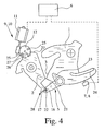
- FIGS. 3 and 4 A further preferred variant of a motor vehicle lock with the above-described memory function is shown in FIGS. 3 and 4. Corresponding components are provided in all figures with the same speedsziffem.
- the motor vehicle lock shown in Figs. 3 and 4 also has the closing elements latch 1 and pawl 2, which cooperate in the manner described above.
- the latch 1 here has only one main catch 3 and no pre-rest.
- Fig. 3 shows the latch 1 in the main latching position when the pawl 2.
- Fig. 4 shows the pawl 2 in its raised position.
- the pawl 2 is held there by a storage element 5.
- the latch 1 is unchanged in its main latching position, but is free of the pawl second
- the storage element 5 is designed as a pivotable lever arrangement.
- the latch 1 comes in their adjustment from the position shown in Fig. 4 right around in its open position into engagement with the control arm 23 and pivots it in Fig. 4 on the left, which in turn corresponds to the above-mentioned positive coupling. This leads to an adjustment of the storage element 5 in the excavated position.
- the latch 1 has a control contour 24.
- a motor release of the pawl 2 is also provided here.
- a storage drive 9 is provided, which may be configured as an additional drive or is an already existing drive.
- an opening drive 10 is again provided, which is the storage drive 9 at the same time.
- the opening drive 10 has a motor 11 and an actuator 12, which is equipped with two pins 25.
- the pawl 2 has a recess 26 and stop surfaces 27, which allow an adjustment of the pawl 2 in the direction of arrival and in Ausheberaum. At the same time a block operation can be realized by the stop surfaces.
- the storage element 5 is now an at least partially preferably made of plastic lever assembly that buckles in the storage state (Fig. 4) under the above increased force, bends away or otherwise causes the release of the pawl.
- the pawl 2 has an engagement member 28 for engagement with the storage element 5 and that the engagement member 28 is preferably made of plastic and buckles in the storage state under the above increased force, bends away or otherwise the release of the pawl 2 causes.
- the above deformation may be an elastic deformation or a non-elastic deformation.
- the deformable component is interpreted as meaning that the pawl 2 can be kept in its excavated position by the storage element 5 in normal operation and that only when the motor release the pawl 2, so under increased force, a corresponding, the pawl 2 releasing deformation takes place.
- the motor release of the pawl 2 from the memory state so the motorized adjustment of the pawl 2 under increased force in the direction of its sunken position. Due to the increased force effect, the memory element 5 and / or the pawl 2 deformed at least partially, which finally causes the release of the pawl 2.
- the deformability of the memory element 5 on the one hand and / or the pawl 2 on the other hand can be supported by a special shaping of these components.
- An example of this is that the memory element 5 and / or the pawl 2 in any case in sections has a substantially arcuate and thus yielding shape.
- the storage lever 5 as a whole has a curved shape, which helps the storage lever 5 together with its material parameters to the desired flexibility.
Landscapes
- Lock And Its Accessories (AREA)
- Handcart (AREA)
- Load-Engaging Elements For Cranes (AREA)
- Vehicle Body Suspensions (AREA)
Abstract
Description
Die vorliegende Erfindung betrifft ein Kraftfahrzeugschloß gemäß dem Oberbegriff des Anspruchs 1. Vorliegend sind unter dem Begriff Kraftfahrzeugschloß alle Arten von Tür-, Hauben- oder Klappenschlössern zusammengefaßt.The present invention relates to a motor vehicle lock according to the preamble of
Heutige Kraftfahrzeugschlösser weisen üblicherweise die Schließelemente Schloßfalle und Sperrklinke auf, wobei die Schloßfalle bei geschlossener Fahrzeugtür mit einem an der Kraftfahrzeugkarosserie befestigten Schließbügel in Eingriff steht. Die Schloßfalle läßt sich von der in ihrer eingefallenen Stellung befindlichen Sperrklinke in einer Hauptraststellung und in einer ggf. vorhandenen Vorraststellung halten. Hierfür weist die Schloßfalle eine Hauptrast und ggf. eine Vorrast auf, die mit einer an der Sperrklinke angeordneten Sperrnase in Eingriff bringbar sind. Durch das Ausheben der Sperrklinke wird die Schloßfalle in Richtung ihrer Öffnungsstellung freigegeben. Hierbei sind die Schloßfalle üblicherweise in ihre Öffnungsstellung und die Sperrklinke in ihre eingefallene Stellung vorgespannt.Today motor vehicle locks usually have the closing elements lock latch and pawl, wherein the latch is in the closed vehicle door with a fastened to the vehicle body striker engaged. The latch can be held by the pawl located in its sunken position in a main latching position and in any pre-engaged position. For this purpose, the latch has a main catch and possibly a pre-rest, which can be brought into engagement with an arranged on the pawl locking lug. By lifting the pawl, the latch is released in the direction of its open position. Here, the latch are usually biased in its open position and the pawl in its sunken position.
Für einen reibungslosen Öffnungsvorgang ist sicherzustellen, daß die Sperrklinke solange in ihrer ausgehobenen Stellung verharrt, bis die Vorrast der Schloßfalle die Sperrnase der Sperrklinke passiert hat. Fällt die Sperrklinke zu früh zurück in ihre eingefallene Stellung, so kommt die Sperrnase der Sperrklinke in Eingriff mit der Vorrast oder sogar mit der Hauptrast, so daß der Öffnungsvorgang unterbrochen wird oder gar nicht erst anläuft. Eine solche Situation entsteht insbesondere dann, wenn die Verstellung der Schloßfalle in die Öffnungsstellung kurzzeitig behindert wird, beispielsweise durch das Vereisen der Fahrzeugtür oder durch die mit dem Gewicht einer Schneeschicht belastete Heckklappe eines Kraftfahrzeugs.For a smooth opening process is to ensure that the pawl as long as it remains in its raised position until the latch of the latch has passed the locking lug of the pawl. If the pawl falls too early back to its sunken position, the locking lug of the pawl comes into engagement with the pre-rest or even with the main catch, so that the opening process is interrupted or not even starts. Such a situation arises in particular when the adjustment of the latch in the open position is temporarily hindered, for example, by the icing of the vehicle door or by the loaded with the weight of a snow layer tailgate of a motor vehicle.
Zur Vermeidung der oben beschriebenen Unterbrechung des Öffnungsvorgangs ist es bekannt, ein Kraftfahrzeugschloß mit einer Speicherfunktion auszustatten (
Eine ähnliche Konzeption zeigt das Kraftfahrzeugschloß (
Schließlich ist ein Kraftfahrzeugschloß mit Speicherfunktion bekannt (
Es darf darauf hingewiesen werden, daß die oben beschriebene Speicherfunktion nicht nur zu einer Erhöhung des Benutzungskomforts führt, sondern in bestimmten Fällen unerläßlich für die Funktionsfähigkeit des Kraftfahrzeugschlosses sein kann. Ein Beispiel hierfür ist ein weiteres bekanntes Kraftfahrzeugschloß (
Bei allen beschriebenen Kraftfahrzeugschlössern wird die Sperrklinke im Speicherzustand vom Speicherelement in ihrer ausgehobenen Stellung gehalten, bis die Schloßfalle ihre Öffnungsstellung erreicht hat. Die Sperrklinke verbleibt damit auch dann in der ausgehobenen Stellung, wenn sich die Fahrzeugtür beispielsweise aufgrund der Vereisung überhaupt nicht öffnen läßt. Fällt die beschriebene Behinderung später unerwartet weg, beispielsweise durch das Schmelzen des Eises während der Fahrt, so wird sich die Fahrzeugtür entsprechend unerwartet öffnen. Dieses Systemverhalten ist mit einem erheblichen Unfallrisiko verbunden.In all motor vehicle locks described the pawl is held in the storage state of the storage element in its raised position until the latch has reached its open position. The pawl thus remains in the excavated position even if the vehicle door can not open, for example, due to the icing. If the disability described later unexpectedly falls away, for example, by the melting of the ice while driving, the vehicle door will open accordingly unexpectedly. This system behavior is associated with a considerable accident risk.
Der vorliegenden Erfindung liegt das Problem zugrunde, das bekannte Kraftfahrzeugschloß mit Speicherfunktion derart auszugestalten und weiterzubilden, daß dessen Betriebssicherheit erhöht wird.The present invention is based on the problem, the known motor vehicle lock with memory function to design and further develop that its reliability is increased.
Das oben angegebene Problem wird bei einem Kraftfahrzeugschloß mit den Merkmalen des Oberbegriffs von Anspruch 1 durch die Merkmale des kennzeichnenden Teils von Anspruch 1 gelöst.The above problem is solved in a motor vehicle lock with the features of the preamble of
Wesentlich ist zunächst die Tatsache, daß die Sperrklinke aus dem Speicherzustand heraus motorisch freigebbar ist. Damit ist die Freigabe der Sperrklinke grundsätzlich jederzeit möglich, so daß ein ungewünschter Verbleib der Sperrklinke im Speicherzustand ohne weiteres verhindert werden kann. Dabei kann die motorische Freigabe der Sperrklinke zusätzlich zu der oben beschriebenen Zwangskopplung vorgesehen werden, die grundsätzlich die Freigabe der Sperrklinke bei der Verstellung der Schloßfalle in ihre Öffnungsstellung bewirkt. Es kann aber auch vorteilhaft sein, daß die Freigabe der Sperrklinke aus dem Speicherzustand heraus ausschließlich motorisch vorgesehen ist. Dies führt dann zu einer besonders einfachen konstruktiven Ausgestaltung.It is essential first of all the fact that the pawl from the memory state is motor-releasable. Thus, the release of the pawl is always possible at any time, so that an unwanted whereabouts of the pawl in the storage state can be easily prevented. In this case, the motor release of the pawl can be provided in addition to the above-described positive coupling, which basically causes the release of the pawl in the adjustment of the latch in its open position. But it may also be advantageous that the release of the pawl from the memory state is provided exclusively by motor. This then leads to a particularly simple structural design.
Die motorische Freigabe der Sperrklinke ist mittels der Steuerungseinrichtung des Kraftfahrzeugschlosses zu einem vorbestimmten Steuerzeitpunkt ansteuerbar. Beispielsweise kann es vorgesehen werden, daß die motorische Freigabe zu jedem Steuerzeitpunkt erfolgt, oder eben, daß die Ansteuerung von weiteren Randbedingungen, beispielsweise von der Stellung der Schloßfalle, abhängig gemacht wird.The motor release of the pawl can be controlled by means of the control device of the motor vehicle lock at a predetermined control time. For example, it may be provided that the motor release takes place at each control time, or even that the control of other boundary conditions, for example, the position of the latch is made dependent.
Die bevorzugte Ausgestaltung gemäß Anspruch 6 zeigt die Mehrfachnutzung des Öffnungsantriebs einerseits für das motorische Ausheben der Sperrklinke und andererseits für die motorische Freigabe der Sperrklinke aus dem Speicherzustand heraus. Hiermit ist eine besonders kompakte Ausgestaltung erreichbar.The preferred embodiment according to
Die bevorzugten Ausgestaltungen gemäß Ansprüchen 8 bis 10 zeigen einfache konstruktive Ausgestaltungen des erfindungsgemäßen Konzepts. Durch die Ausgestaltung des Speicherelements als schwenkbare Hebelanordnung kann die für die Freigabe der Sperrklinke erforderliche Kraft gering gehalten werden.The preferred embodiments according to claims 8 to 10 show simple structural embodiments of the inventive concept. Due to the design of the storage element as a pivotable lever assembly required for the release of the pawl force can be kept low.
Besonders einfach zu realisierende Lösungen zeigen ferner die Ausgestaltungen gemäß Anspruch 11. Durch die hier vorgesehene Verformbarkeit am Speicherelement und/oder an der Sperrklinke kann auf das Ausheben des Speicherelements für die Freigabe der Sperrklinke verzichtet werden.Solutions which are particularly easy to implement further show the embodiments according to
Weitere Einzelheiten, Merkmale, Ziele und Vorteile der vorliegenden Erfindung werden nachfolgend anhand der Zeichnung bevorzugter Ausführungsbeispiele näher erläutert. In der Zeichnung zeigt
- Fig. 1
- ein erfindungsgemäßes Kraftfahrzeugschloß in einer ersten Ausgestaltung bei in der Hauptraststellung befindlicher Schloßfalle, bei eingefallener Sperrklinke und bei ausgehobenem Speicherelement,
- Fig. 2
- das Kraftfahrzeugschloß gemäß Fig. 1 bei in Hauptraststellung befindlicher Schloßfalle, bei ausgehobener Sperrklinke und bei eingefallenem Speicherelement,
- Fig. 3
- ein erfindungsgemäßes Kraftfahrzeugschloß in einer weiteren Ausgestaltung bei in der Hauptraststellung befindlicher Schloßfalle, bei eingefallener Sperrklinke und bei ausgehobenem Speicherelement,
- Fig. 4
- das Kraftfahrzeugschloß gemäß Fig. 3 bei in der Hauptraststellung befindlicher Schloßfalle, bei ausgehobener Sperrklinke und bei eingefallenem Speicherelement.
- Fig. 1
- a motor vehicle lock according to the invention in a first embodiment with the latch in the main latching position, with the latching pawl engaged and with the storage element excavated,
- Fig. 2
- the motor vehicle lock according to FIG. 1 with the latch in the main latching position, with the pawl lifted out and with the latching element inserted,
- Fig. 3
- a motor vehicle lock according to the invention in a further embodiment with the latch in the main latching position, with the latching pawl engaged and with the storage element excavated,
- Fig. 4
- the motor vehicle lock according to FIG. 3 in the case of the main latch position latch, with excavated pawl and sunken memory element.
Das in Fig. 1 dargestellte Kraftfahrzeugschloß ist mit den Schließelementen Schloßfalle 1 und Sperrklinke 2 ausgestattet, wobei die Schloßfalle 1 in eine nicht dargestellte Öffnungsstellung, in die in den Fig. 1 und 2 dargestellte Hauptraststellung und in die nicht dargestellte Vorraststellung bringbar ist. Die Schloßfalle 1 ist vorzugsweise in Richtung ihrer Öffnungsstellung, in Fig. 1 linksherum, vorgespannt. Die Schloßfalle 1 weist eine Hauptrast 3 und eine Vorrast 4 auf. Die Sperrklinke 2 läßt sich in eine in Fig. 1 dargestellte eingefallene Stellung und in eine in Fig. 2 dargestellte ausgehobene Stellung bringen. Es läßt sich Fig. 1 entnehmen, daß die in ihrer eingefallenen Stellung befindliche Sperrklinke 2 die Schloßfalle 1 in der Hauptraststellung (Fig. 1) sowie in der Vorraststellung hält und daß die in ihrer ausgehobenen Stellung befmdliche Sperrklinke 2 die Schloßfalle 1 in Richtung ihrer Öffnungsstellung freigibt (Fig. 2).The motor vehicle lock shown in Fig. 1 is equipped with the closing elements latch 1 and
Der Sperrklinke 2 ist ein Speicherelement 5 zugeordnet, das die Sperrklinke 2 nach deren Ausheben in der ausgehobenen Stellung hält, was dem bereits angesprochenen Speicherzustand entspricht. Dieser Speicherzustand ist in Fig. 2 dargestellt.The
Vorliegend läßt sich die Sperrklinke 2 motorisch ausheben, wobei der Aushebevorgang im Blockbetrieb erfolgt. In ihrer ausgehobenen Stellung kommt der Sperrklinke 2 eine entsprechend blockierende Wirkung zu, so daß sicherzustellen ist, daß die Sperrklinke 2 lange genug in ihrer ausgehobenen Stellung verharrt. Dies wird hier durch das Speicherelement 5 gewährleistet.In the present case, the
Der Speicherzustand wird solange gehalten, bis ein weiterer Funktionszustand des Kraftfahrzeugschlosses erreicht ist. In bevorzugter Ausgestaltung (Fig. 1 bis 4) ist der weitere Funktionszustand jedenfalls dann erreicht, wenn die Schloßfalle 1 ihre Öffnungsstellung erreicht hat. Dies wird vorzugsweise durch eine entsprechende Zwangskopplung zwischen der Schloßfalle 1 und dem Speicherelement 5 gewährleistet, wie im folgenden noch gezeigt wird. Ein solcher weiterer Funktionszustand kann zusätzlich auf andere Weise definiert sein, wie beispielsweise durch einen bestimmten steuerungstechnischen Zustand, wie ebenfalls noch gezeigt wird.The memory state is held until a further functional state of the motor vehicle lock is reached. In a preferred embodiment (FIGS. 1 to 4), the further functional state is in any case achieved when the
Um elektrische Funktionen des Kraftfahrzeugschlosses wie die oben beschriebene, ggf. vorhandene motorische Öffnungsfunktion, eine Zentralverriegelungsfunktion o. dgl. ansteuern zu können, weist das Kraftfahrzeugschloß eine Steuerungseinrichtung 6 auf, die entweder im Kraftfahrzeugschloß selbst oder separat davon im Kraftfahrzeug angeordnet ist. Die Steuerungseinrichtung 6 ist in der Zeichnung lediglich schematisch angedeutet.In order to be able to control electrical functions of the motor vehicle lock, such as the motor opening function described above, a central locking function or the like, the motor vehicle lock has a
Wesentlich ist nun die Tatsache, daß die Sperrklinke 2 aus dem in Fig. 2 dargestellten Speicherzustand heraus motorisch freigebbar ist und dann, vom Speicherelement 5 unbehindert, in Richtung ihrer eingefallenen Stellung verstellbar ist. Die Sperrklinke 2 ist vorzugsweise in Richtung ihrer eingefallenen Stellung vorgespannt, so daß sie nach der Freigabe gewissermaßen in Richtung ihrer eingefallenen Stellung schnappt.It is essential now that the
Die motorische Freigabe der Sperrklinke 2 ist mittels der Steuerungseinrichtung 6 zu einem vorbestimmten Steuerzeitpunkt ansteuerbar. Dabei kann der Steuerzeitpunkt als Ende einer vorbestimmten Zeitspanne, die mit dem Ausheben der Sperrklinke 2 beginnt, definiert sein. Dann erfolgt die motorische Freigabe der Sperrklinke 2 grundsätzlich beispielsweise einige Sekunden nach dem Ausheben der Sperrklinke 2.The motor release of the
Besonders vorteilhaft ist es aber, wenn der Steuerzeitpunkt als der nach dem Ausheben der Sperrklinke 2 liegende Zeitpunkt einer Signalübertragung von der übrigen Fahrzeugelektrik an die Steuerungseinrichtung 6 des Kraftfahrzeugschlosses definiert ist. Diese Signalübertragung kann beispielsweise beim Einschalten der Zündung oder beim Anfahren des Kraftfahrzeugs erfolgen.But it is particularly advantageous if the control time is defined as the time after the lifting of the
Wie oben beschrieben, kann es vorgesehen werden, daß die Ansteuerung der motorischen Freigabe der Sperrklinke 2 grundsätzlich in jedem Steuerzeitpunkt, also nach jedem Ausheben der Sperrklinke 2, erfolgt.As described above, it can be provided that the control of the motor release of the
In besonders bevorzugter Ausgestaltung erfolgt die Ansteuerung der motorischen Freigabe der Sperrklinke 2 allerdings selektiv in dem Sinne, daß nicht in jedem Steuerzeitpunkt eine entsprechende Ansteuerung vorgenommen wird. Hierfür ist der Steuerungseinrichtung 6 eine Schloßfallenüberwachung 7 hinsichtlich der Stellung der Schloßfalle 1 zugeordnet. Im in den Fig. 1 und 2 dargestellten Ausführungsbeispiel weist die Schloßfallenüberwachung 7 einen einfachen Tastschalter 8 auf, der das Verschwenken der Schloßfalle 1 in die Öffnungsstellung an die Steuerungseinrichtung 6 meldet. Selbstverständlich sind für eine solche Schloßfallenüberwachung 7 zahlreiche aus dem Stand der Technik bekannte Sensoren anwendbar. Eine besonders effektive Betriebsweise erreicht man nun dadurch, daß die Steuerungseinrichtung 6 dann, wenn die Schloßfalle 1 zwischen dem Zeitpunkt des Aushebens der Sperrklinke 2 und dem Steuerzeitpunkt noch nicht vollständig ihre Öffnungsstellung erreicht hat, die motorische Freigabe der Sperrklinke 2 aus dem Speicherzustand heraus ansteuert. Dies ist der oben beschriebene Fehlerzustand, wenn nämlich die Verstellung der Schloßfalle 1 in Richtung ihrer Öffnungsstellung, beispielsweise durch Vereisung, behindert ist.In a particularly preferred embodiment, however, the activation of the motor release of the
Es darf darauf hingewiesen werden, daß die Schloßfallenüberwachung 7 nicht notwendigerweise unmittelbar an der Schloßfalle 1 erfolgen muß. Beispielsweise kann auch das Öffnen der Fahrzeugtür indirekt Aufschluß über die Verstellung der Schloßfalle 1 in ihre Öffnungsstellung geben. Dies ist insofern vorteilhaft, als die Fahrzeugtür in der Regel ohnehin mit einem AJAR-Schalter ausgestaltet ist.It should be noted that the lock trap monitoring 7 does not necessarily have to take place directly on the
Es ist noch eine weitere vorteilhafte Möglichkeit der selektiven Ansteuerung der motorischen Freigabe der Sperrklinke 2 denkbar. Nach dieser bevorzugten Ausgestaltung ist eine Sperrklinkenüberwachung 7a hinsichtlich der Stellung der Sperrklinke 2 vorgesehen, die wiederum von der Steuerungseinrichtung 6 abgefragt werden kann. Vorliegend weist auch die Sperrklinkenüberwachung 7a einen einfachen Tastschalter 8a auf, der das Verschwenken der Sperrklinke 2 in die ausgehobene Stellung an die Steuerungseinrichtung 6 meldet. Befindet sich nun die Sperrklinke 2 im Steuerzeitpunkt, der ja vorzugsweise dem Zeitpunkt des Aushebens der Sperrklinke 2 nachgelagert ist, unverändert in ihrer ausgehobenen Stellung, so liegt der obige Fehlerzustand vor und die Steuerungseinrichtung 6 steuert die motorische Freigabe der Sperrklinke 2 an. Zu einem besonders sicheren Überwachungsergebnis gelangt man schließlich durch die zusätzliche Abfrage der oben genannten Schloßfallenüberwachung 7.It is still another advantageous possibility of selective control of the motor release of the
Wie sich aus den obigen Ausführungen ergibt, ist die motorische Freigabe der Sperrklinke 2 insbesondere in Verbindung mit der oben angesprochenen Zwangskopplung zwischen Schloßfalle 1 und Speicherelement 5 vorteilhaft. Durch diese Zwangskopplung bewirkt eine Verstellung der Schloßfalle 1 in die Öffnungsstellung grundsätzlich eine Freigabe der Sperrklinke 2 aus dem Speicherzustand heraus. Die Zwangskopplung einerseits und die motorische Freigabe der Sperrklinke 2 andererseits stellen dann einander ergänzende Maßnahmen dar.As can be seen from the above statements, the motor release of the
Wenn nämlich im Fehlerzustand die Verstellung der Schloßfalle 1 nach dem Ausheben der Sperrklinke 2 in die Öffnungsstellung behindert wird, kommt die Zwangskopplung zwischen Schloßfalle 1 und Speicherelement 5 nicht zum tragen, wodurch wiederum die Sperrklinke 2 in ihrer ausgehobenen Stellung verbleibt. Durch die rechtzeitig vorgenommene, motorische Freigabe der Sperrklinke 2 wird dann vermieden, daß nach dem Wegfall der Behinderung, also beispielsweise nach dem Schmelzen des Eises bei zuvor vereister Fahrzeugtür, ein unerwartetes Öffnen der Fahrzeugtür erfolgt. Die Sperrklinke 2 fällt nach deren Freigabe vorteilhafterweise zurück in die Hauptrast 3 oder jedenfalls in die Bewegungsbahn der Vorrast 4 der Schloßfalle 1, soweit die Schloßfalle 1 nicht bereits weitgehend in Richtung ihrer Öffnungsstellung verstellt ist.Namely, if in the error state, the adjustment of the
Für die motorische Freigabe der Sperrklinke 2 ist vorliegend ein Speicherantrieb 9 vorgesehen, der je nach Anwendungsfall vorteilhaft als zusätzlicher Antrieb ausgestaltet sein kann. In besonders bevorzugter Ausgestaltung wird allerdings ein ohnehin vorhandener Antrieb als Speicherantrieb 9 genutzt. Im dargestellten Ausführungsbeispiel weist das Kraftfahrzeugschloß einen Öffnungsantrieb 10 zum motorischen Ausheben der Sperrklinke 2 auf, der gleichzeitig die Funktion des Speicherantriebs 9 übernimmt. Für eine derartige Doppelnutzung können aber auch ein Zentralverriegelungsantrieb oder ein Schließhilfsantrieb dienen.For the motor release of the
Im in Fig. 1 dargestellten und insoweit bevorzugten Ausführungsbeispiel weist der Öffnungsantrieb 10 ein von einem Motor 11 angetriebenes Stellelement 12 auf. Das Stellelement 12 weist eine Steuerkontur 13 auf, die mit einem Mitnehmer 14 an der Sperrklinke 2 in Eingriff bringbar ist. Zum Ausheben der Sperrklinke 2 wird das Stellelement 12 aus der in Fig. 1 dargestellten Stellung heraus rechtsherum gedreht, bis die Steuerkontur 13 mit dem Mitnehmer 14 in Eingriff kommt und die Sperrklinke 2 linksherum verschwenkt.In the preferred embodiment shown in FIG. 1, the opening drive 10 has an
Das Speicherelement 5 ist in eine eingefallene Stellung bringbar (Fig. 2), in der das Speicherelement 5 die Sperrklinke 2 in ihrer ausgehobenen Stellung hält. Das Speicherelement 5 ist ferner in eine ausgehobene Stellung bringbar (Fig. 1), in der das Speicherelement 5 die Sperrklinke 2 freigibt.The
Dadurch, daß das Speicherelement 5 im dargestellten und insoweit bevorzugten Ausführungsbeispiel in seine eingefallene Stellung vorgespannt ist, bewirkt das Ausheben der Sperrklinke 2 durch den Öffnungsantrieb 10 grundsätzlich die Verstellung des Speicherelements 5 in seine eingefallene Stellung (Fig. 2).Characterized in that the
Im Einzelnen wird beim Ausheben der Sperrklinke 2 durch den Öffnungsantrieb 10 der Mitnehmer 14 in die Bewegungsbahn eines am Stellelement 12 angeordneten Anschlags 15 verstellt. Dadurch, daß das Speicherelement 5 die Sperrklinke 2 in dieser Stellung hält, ist gleichzeitig der Blockbetrieb für den Öffnungsantrieb 10 gewährleistet.Specifically, when the
Im in Fig. 1 dargestellten und insoweit bevorzugten Ausführungsbeispiel ist das Speicherelement 5 als schwenkbare Hebelanordnung ausgestaltet. Grundsätzlich kann das Speicherelement 5 aber auch als linear beweglicher Schieber o. dgl. ausgestaltet sein.In the preferred embodiment shown in FIG. 1, the
Für die Realisierung des oben beschriebenen Speicherzustands weist das Speicherelement 5 einen Anschlag 16 auf, der mit einem an der Sperrklinke 2 angeordneten Gegenanschlag 17 in Eingriff bringbar ist. Ferner weist das Speicherelement 5 einen Steuerarm 18 auf, dessen Verschwenken, in Fig. 1 rechtsherum, die Verstellung des Speicherelements 5 in die ausgehobene Stellung bewirkt.For the realization of the memory state described above, the
Fig. 2 läßt sich entnehmen, daß der Steuerarm 18 im Speicherzustand in der Bewegungsbahn des am Stellelement 12 angeordneten Anschlags 15 liegt. Durch eine Drehung des Stellelements 12 aus der in Fig. 2 dargestellten Stellung linksherum passiert die Steuerkontur 13 mit ihrer Teilkontur 13a den Mitnehmer 14 und drückt die Sperrklinke 2 dabei kurzzeitig in eine Überhubstellung. Hierfür ist die Teilkontur 13a mit einer entsprechenden Schräge ausgestattet. Bei weiterer Drehung des Stellelements 12 kommt dann der Anschlag 15 in Eingriff mit dem Steuerarm 18 und verstellt damit das Speicherelement 5 rechtsherum in dessen ausgehobene Stellung. Dadurch wird die Sperrklinke 2 freigegeben und schnappt nun in Richtung ihrer eingefallenen Stellung, in Fig. 2 rechtsherum. Ein Anschlag 19 an der Sperrklinke 2 kommt schließlich in die Bewegungsbahn einer Anlagekante 20 der Steuerkontur 13 und blockiert die weitere Bewegung des Öffnungsantriebs 10, so daß auch die motorische Freigabe der Sperrklinke 2 im Blockbetrieb gewährleistet ist.Fig. 2 can be seen that the
Nachdem nun bei dem oben beschriebenen Vorgang der motorischen Freigabe der Sperrklinke 2 die Sperrklinke 2 in Richtung ihrer eingefallenen Stellung verschwenkt ist und auch der am Stellelement 12 angeordnete Anschlag 15 außer Eingriff mit dem Speicherelement 5 gekommen ist, fällt das Speicherelement 5 mit einer Anlagekante 21 auf eine entsprechende Anlagekante 22 der Sperrklinke 2. Hierdurch wird das Speicherelement 5 in seiner ausgehobenen Stellung gehalten, bis die Sperrklinke 2 wieder durch den Öffnungsantrieb 10 ausgehoben wird. Besonders hervorzuheben ist die Tatsache, daß der Steuerarm 18 des Speicherelements 5 bei in der ausgehobenen Stellung befindlichem Speicherelement 5 außer Eingriff mit dem Speicherantrieb 9, hier also mit dem Öffnungsantrieb 10 steht. Dadurch läßt sich die Doppelnutzung des Öffnungsantriebs 10 in oben beschriebener Weise ohne größeren konstruktiven Aufwand realisieren.After now in the above-described process of the motor release of the
Es wurde bereits darauf hingewiesen, daß vorzugsweise auch eine nicht motorische Freigabe der Sperrklinke 2 aus dem Speicherzustand heraus immer dann gewährleistet ist, wenn die Schloßfalle 1 nach dem Ausheben der Sperrklinke 2 in ihre Öffnungsstellung verschwenkt, was ja den Normalzustand darstellt. Hierfür ist das Speicherelement 5 mit einem weiteren Steuerarm 23 ausgestattet, mit dem eine Steuerkontur 24 an der Schloßfalle 1 im Speicherzustand bei deren Verstellung in ihre Öffnungsstellung in Eingriff kommt und dessen resultierendes Verschwenken, in Fig. 2 rechtsherum, zu einem Ausheben des Speicherelements 5 führt - Zwangskopplung -.It has already been pointed out that preferably also a non-motor release of the
Eine weitere bevorzugte Variante eines Kraftfahrzeugschlosses mit der oben beschriebenen Speicherfunktion ist in den Fig. 3 und 4 dargestellt. Einander entsprechende Komponenten sind in allen Figuren mit den gleichen Bezugsziffem versehen.A further preferred variant of a motor vehicle lock with the above-described memory function is shown in FIGS. 3 and 4. Corresponding components are provided in all figures with the same Bezugsziffem.
Das in den Fig. 3 und 4 dargestellte Kraftfahrzeugschloß weist ebenfalls die Schließelemente Schloßfalle 1 und Sperrklinke 2 auf, die in oben beschriebener Weise zusammenwirken. Die Schloßfalle 1 weist hier lediglich eine Hauptrast 3 und keine Vorrast auf.The motor vehicle lock shown in Figs. 3 and 4 also has the closing elements latch 1 and
Fig. 3 zeigt die Schloßfalle 1 in der Hauptraststellung bei eingefallener Sperrklinke 2. Fig. 4 zeigt dagegen die Sperrklinke 2 in ihrer ausgehobenen Stellung. Die Sperrklinke 2 wird dort durch ein Speicherelement 5 gehalten. Die Schloßfalle 1 steht unverändert in ihrer Hauptraststellung, ist allerdings frei von der Sperrklinke 2.Fig. 3 shows the
Auch bei diesem Ausführungsbeispiel ist das Speicherelement 5 als schwenkbare Hebelanordnung ausgestaltet. Allerdings ist hier nur ein einziger Steuerarm 23 in obigem Sinne vorgesehen. Die Schloßfalle 1 kommt bei deren Verstellung aus der in Fig. 4 dargestellten Stellung rechtsherum in ihre Öffnungsstellung in Eingriff mit dem Steuerarm 23 und verschwenkt diesen in Fig. 4 linksherum, was wiederum der oben angesprochenen Zwangskopplung entspricht. Dies führt zu einer Verstellung des Speicherelements 5 in die ausgehobene Stellung. Für diesen Eingriff mit dem Speicherelement 5 weist die Schloßfalle 1 eine Steuerkontur 24 auf. Durch das Ausheben des Speicherelements 5 wird, wie oben beschrieben, die Sperrklinke 2 freigegeben.Also in this embodiment, the
Neben der obigen für den Normalzustand vorgesehenen Freigabe der Sperrklinke 2 ist auch hier eine motorische Freigabe der Sperrklinke 2 vorgesehen. Für die motorische Freigabe der Sperrklinke 2 ist ein Speicherantrieb 9 vorgesehen, der als zusätzlicher Antrieb ausgestaltet sein kann oder aber ein ohnehin vorhandener Antrieb ist. Im in den Fig. 3 und 4 dargestellten Ausführungsbeispiel ist wieder ein Öffnungsantrieb 10 vorgesehen, der gleichzeitig der Speicherantrieb 9 ist. Der Öffnungsantrieb 10 weist einen Motor 11 und ein Stellelement 12 auf, das mit zwei Zapfen 25 ausgestattet ist. Die Sperrklinke 2 weist eine Ausnehmung 26 und Anschlagflächen 27 auf, die eine Verstellung der Sperrklinke 2 in Einfallrichtung und in Ausheberichtung ermöglichen. Gleichzeitig ist durch die Anschlagflächen ein Blockbetrieb realisierbar.In addition to the above provided for the normal state release of the
Vorliegend ist von besonderer Bedeutung, daß die Sperrklinke 2 aus der in Fig. 4 dargestellten Stellung - aus dem Speicherzustand heraus - mittels des Öffnungsantriebs 10 unter erhöhter Krafteinwirkung in Richtung ihrer eingefallenen Stellung verstellbar ist. In besonders bevorzugter Ausgestaltung ist das Speicherelement 5 nun eine zumindest teilweise vorzugsweise aus Kunststoff bestehende Hebelanordnung, die im Speicherzustand (Fig. 4) unter obiger erhöhter Kraftwirkung ausknickt, wegbiegt oder anderweit die Freigabe der Sperrklinke bewirkt.In the present case is of particular importance that the
In umgekehrter Weise kann es aber auch vorgesehen sein, daß die Sperrklinke 2 ein Eingriffselement 28 für den Eingriff mit dem Speicherelement 5 aufweist und daß das Eingriffselement 28 vorzugsweise aus Kunststoff besteht und im Speicherzustand unter obiger erhöhter Kraftwirkung ausknickt, wegbiegt oder anderweit die Freigabe der Sperrklinke 2 bewirkt.Conversely, it may also be provided that the
In diesem in den Fig. 3 und 4 dargestellten Ausführungsbeispiel ist also nicht ein Ausheben des Speicherelements 5 für die motorische Freigabe der Sperrklinke 2 erforderlich, sondern lediglich eine Verformung des Speicherelements 5 und/oder der Sperrklinke 2 unter erhöhter Krafteinwirkung, die vorliegend durch den Öffnungsantrieb 10 bereitgestellt wird.In this embodiment shown in FIGS. 3 and 4, therefore, not a lifting of the
Bei der obigen Verformung kann es sich um eine elastische Verformung oder um eine nicht elastische Verformung handeln. Jedenfalls ist der verformbare Bestandteil so auszulegen, daß die Sperrklinke 2 im Normalbetrieb vom Speicherelement 5 in ihrer ausgehobenen Stellung gehalten werden kann und daß erst bei der motorischen Freigabe der Sperrklinke 2, also unter erhöhter Kraftwirkung, eine entsprechende, die Sperrklinke 2 freigebende Verformung erfolgt.The above deformation may be an elastic deformation or a non-elastic deformation. In any case, the deformable component is interpreted as meaning that the
Bei diesem weiteren Ausführungsbeispiel umfaßt die motorische Freigabe der Sperrklinke 2 aus dem Speicherzustand heraus also die motorische Verstellung der Sperrklinke 2 unter erhöhter Kraftwirkung in Richtung ihrer eingefallenen Stellung. Durch die erhöhte Kraftwirkung verformt sich das Speicherelement 5 und/oder die Sperrklinke 2 zumindest teilweise, was schließlich die Freigabe der Sperrklinke 2 bewirkt.In this further embodiment, the motor release of the
Die Verformbarkeit des Speicherelements 5 einerseits und/oder der Sperrklinke 2 andererseits läßt sich durch eine spezielle Formgebung dieser Komponenten unterstützen. Ein Beispiel hierfür besteht darin, daß das Speicherelement 5 und/oder die Sperrklinke 2 jedenfalls abschnittsweise eine im wesentlichen bogenförmige und dadurch nachgiebige Formgebung aufweist. Es kann aber auch vorteilhaft sein, wenn beispielsweise der Speicherhebel 5 insgesamt eine Bogenform aufweist, die dem Speicherhebel 5 zusammen mit seinen Materialparametern zu der gewünschten Nachgiebigkeit verhilft.The deformability of the
Für weitere vorteilhafte Varianten des in den Fig. 3 und 4 dargestellten Ausführungsbeispiels darf auf die obige Beschreibung des in den Fig. 1 und 2 dargestellten Ausführungsbeispiels verwiesen werden.For further advantageous variants of the embodiment shown in FIGS. 3 and 4 may be made to the above description of the embodiment shown in FIGS. 1 and 2.
Claims (12)
- Motor vehicle lock with locking elements - a lock latch (1) and pawl (2), wherein the lock latch (1) can be brought into an open position, a main latching position and, if appropriate, into a preliminary latching position, and wherein the pawl (2) can be brought into an engaged position and into a raised position, wherein the pawl (2) in its engaged position holds the lock latch (1) in the main latching position and in the possibly provided preliminary latching position, and wherein the pawl (2) in its raised position releases the lock latch (1) in the direction of its open position, wherein the pawl (2) is assigned a storage element (5) which keeps the pawl (2), after raising thereof, in the raised position - storage state - until a further functional state of the motor vehicle lock is reached, in particular until the lock latch (1) has reached its opening position, and with a control device (6) in the motor vehicle lock or separately therefrom in the motor vehicle, by means of which device individual functions of the motor vehicle lock can be activated, characterized in that the pawl (2) can be released by motor from the storage state and then, unobstructed by the storage element (5), can be displaced in the direction of its engaged position, and in that the motorized release of the pawl (2) can be activated by means of the control device (6) at a predetermined control time.
- Motor vehicle lock according to Claim 1, characterized in that the control time is defined as the end of a predetermined period of time which begins with the raising of the pawl (2).
- Motor vehicle lock according to Claim 1 or 2, characterized in that the control time is defined as the time after the raising of the pawl (2) at which a signal is transmitted by the rest of the vehicle electrics to the control device (6) of the motor vehicle lock, preferably in that this signal transmission takes place when the ignition switched on or the motor vehicle is started.
- Motor vehicle lock according to one of the preceding claims, characterized in that the control device (6) is assigned a lock-latch monitoring means (7) to monitor the position of the lock latch (1) and/or a pawl monitoring means (7a) to monitor the position of the pawl (2) and in that, at the control time, the control device (6) activates the motorized release of the pawl (2) as a function of the lock-latch monitoring means (7) and/or of the pawl monitoring means (7a), preferably in that the control device (6) activates the motorized release of the pawl (2) if, since the raising of the pawl (2), the lock latch (1) by the control time has not yet completely reached its opening position, or in that the control device (6) activates the motorized release of the pawl (2) whenever, at the control time, the pawl (2) is in the raised position and, preferably, if at the same time the lock latch (1) has not yet completely reached its opening position.
- Motor vehicle lock according to one of the preceding claims, characterized in that the lock latch (1) is coupled to the storage element (5) in such a manner that displacement of the lock latch (1) into the opening position causes the pawl (2) to be released from the storage state.
- Motor vehicle lock according to one of the preceding claims, characterized in that a storage drive (9) is provided for the motorized release of the pawl (2), preferably in that an opening drive (10) is provided for the motorized raising of the pawl (2), and in that the opening drive (10) is at the same time the storage drive (9).
- Motor vehicle lock according to one of the preceding claims, characterized in that the storage element (5) can be brought into an engaged position in which the storage element (5) holds the pawl (2) in its raised position, and in that the storage element (5) can be brought into a raised position in which the storage element (5) releases the pawl (2), preferably in that the storage element (5) is prestressed into its engaged position.
- Motor vehicle lock according to one of the preceding claims, characterized in that the storage element (5) is configured as a pivotable lever arrangement.
- Motor vehicle lock according to Claims 6 and 8, characterized in that the storage element (5) has at least one control arm (18), the pivoting of which in a pivoting direction brings about the displacement of the storage element (5) into the raised position, and in that the control arm (8) is or can be brought into engagement with the storage drive (9) and, as a result, can be pivoted by motor, preferably in that the control arm (9) is only in engagement with the storage drive (9) when the storage element (5) is in the engaged position.
- Motor vehicle lock according to Claim 8 and, if appropriate, according to Claim 9, characterized in that the storage element (5) has an optional further control arm (23) with which the lock latch (1) comes into engagement in the storage state during its displacement into its opening position and the resulting pivoting of which leads to the storage element (5) being raised.
- Motor vehicle lock according to one of the preceding claims, characterized in that the storage element (5) is a lever arrangement which is at least partially preferably composed of plastic and, in the storage state, buckles or bends away under increased action of force or in some other way brings about the release of the pawl (2), and/or, preferably, in that the pawl (2) has an engagement element (28) for engagement with the storage element (5), and in that the engagement element (28) is preferably composed of plastic and, in the storage state, buckles or bends away under increased action of force or brings about the release of the pawl (2) in another way, and/or, furthermore preferably, in that the storage element (5) and/or the pawl (2) have/has, at any rate in some sections, an essentially curved and, as a result, flexible shaping.
- Motor vehicle lock according to Claim 11, characterized in that the motorized release of the pawl (2) includes the motorized displacement of the pawl (2) in the direction of its engaged position under increased action of force, as a result of which the storage element (5) and/or the pawl (2) is at least partially deformed, which finally brings about the release of the pawl (2).
Applications Claiming Priority (1)
| Application Number | Priority Date | Filing Date | Title |
|---|---|---|---|
| DE200410042966 DE102004042966A1 (en) | 2004-09-02 | 2004-09-02 | Motor vehicle lock |
Publications (2)
| Publication Number | Publication Date |
|---|---|
| EP1632626A1 EP1632626A1 (en) | 2006-03-08 |
| EP1632626B1 true EP1632626B1 (en) | 2007-08-01 |
Family
ID=35453504
Family Applications (1)
| Application Number | Title | Priority Date | Filing Date |
|---|---|---|---|
| EP20050017653 Not-in-force EP1632626B1 (en) | 2004-09-02 | 2005-08-12 | Motor vehicle lock |
Country Status (4)
| Country | Link |
|---|---|
| US (1) | US7452013B2 (en) |
| EP (1) | EP1632626B1 (en) |
| AT (1) | ATE368787T1 (en) |
| DE (2) | DE102004042966A1 (en) |
Families Citing this family (19)
| Publication number | Priority date | Publication date | Assignee | Title |
|---|---|---|---|---|
| DE102006019515A1 (en) * | 2006-04-13 | 2007-10-18 | Rahrbach Gmbh | Multi-level door lock |
| EP2310601B1 (en) * | 2008-05-26 | 2016-02-24 | Magna Closures SpA | Double pawl vehicle latch |
| DE102008028256A1 (en) * | 2008-06-13 | 2009-12-24 | Kiekert Ag | Locking device with two pawls and motor-driven actuator |
| CA2697768A1 (en) * | 2009-03-25 | 2010-09-25 | Magna Closures Inc. | Closure latch for vehicle door |
| DE102009034904B4 (en) | 2009-07-27 | 2019-07-11 | Magna BÖCO GmbH | Locking device for a vehicle door |
| DE102009037037B4 (en) * | 2009-08-13 | 2018-10-18 | BÖCO Böddecker & Co. GmbH & Co. KG | Locking device for a vehicle door |
| DE202009016636U1 (en) † | 2009-12-09 | 2011-04-21 | BROSE SCHLIEßSYSTEME GMBH & CO. KG | Motor vehicle lock |
| CA2788576A1 (en) | 2010-02-05 | 2011-08-11 | Magna Closures S.P.A. | Vehicular latch with double pawl arrangement |
| EP2602184B1 (en) * | 2011-12-09 | 2018-03-07 | Safran Landing Systems | A latching box with an unlocking actuator having a cylindrical cam |
| KR101372022B1 (en) * | 2012-08-24 | 2014-03-07 | 기아자동차주식회사 | 2 step open hood latch apparatus for vehicle |
| DE102013103245A1 (en) * | 2013-03-28 | 2014-10-02 | Kiekert Aktiengesellschaft | Motor vehicle door lock |
| DE202013103327U1 (en) | 2013-07-24 | 2014-10-27 | BROSE SCHLIEßSYSTEME GMBH & CO. KG | Motor vehicle lock |
| FR3014472B1 (en) * | 2013-12-10 | 2017-10-06 | Inteva Products Llc | ASSEMBLY AND DOOR LATCH SYSTEM |
| DE102016116616A1 (en) | 2016-09-06 | 2018-03-08 | Kiekert Ag | Motor vehicle door lock |
| DE102017121319A1 (en) * | 2017-09-14 | 2019-03-14 | Huf Hülsbeck & Fürst Gmbh & Co. Kg | Lock arrangement of a motor vehicle |
| DE102017124519A1 (en) * | 2017-10-20 | 2019-04-25 | Kiekert Ag | Motor vehicle door lock |
| DE102018101142A1 (en) * | 2018-01-19 | 2019-07-25 | Kiekert Ag | MOTOR VEHICLE LOCK |
| DE102018120435A1 (en) * | 2018-08-22 | 2020-02-27 | Kiekert Ag | Motor vehicle lock |
| DE102021111341A1 (en) | 2021-05-03 | 2022-11-03 | Kiekert Aktiengesellschaft | motor vehicle lock |
Family Cites Families (16)
| Publication number | Priority date | Publication date | Assignee | Title |
|---|---|---|---|---|
| DE19520359A1 (en) | 1995-06-07 | 1996-12-12 | Bocklenberg & Motte Bomoro | Lock for bonnet or door of motor vehicle |
| US5613716A (en) * | 1996-01-25 | 1997-03-25 | General Motors Corporation | Electronic vehicle door unlatch control |
| DE19614122B4 (en) * | 1996-04-11 | 2006-04-27 | Brose Schließsysteme GmbH & Co.KG | Motor vehicle flap lock or door lock |
| DE19617428C2 (en) * | 1996-05-01 | 1998-06-10 | Kiekert Ag | Motor vehicle door lock with electrical door lock and electrical closing aid for the assigned motor vehicle door |
| DE19632915A1 (en) * | 1996-05-21 | 1997-11-27 | Bosch Gmbh Robert | Method for controlling an electrically operated motor vehicle door lock or the like |
| EP0808977B1 (en) * | 1996-05-21 | 2000-08-16 | Robert Bosch Gmbh | Method for controlling an electrically actuated vehicle door lock |
| US6422615B1 (en) * | 1998-07-20 | 2002-07-23 | Mannesmann Vdo Ag | Closure device with shutting aid |
| FR2782111B1 (en) | 1998-08-05 | 2002-12-06 | Valeo Securite Habitacle | IMPROVED ELECTRIC LOCK FOR VEHICLE OPENING ELEMENT |
| DE10019668A1 (en) * | 2000-04-19 | 2001-10-31 | Hs Products Karosseriesysteme | Locking device, in particular for a trunk lid |
| GB0011991D0 (en) * | 2000-05-19 | 2000-07-05 | Meritor Light Vehicle Sys Ltd | Latch assembly and vehicle including such a latch assembly |
| JP3902908B2 (en) * | 2000-07-07 | 2007-04-11 | 株式会社大井製作所 | Trunk lid lock drive device for automobile |
| US20020167175A1 (en) * | 2001-01-30 | 2002-11-14 | Robert Bosch Gmbh | Motor vehicle gate lock arrangement |
| US6565132B2 (en) * | 2001-06-28 | 2003-05-20 | Delphi Technologies, Inc. | Vehicle compartment latch |
| CA2469258C (en) * | 2001-12-12 | 2010-11-16 | Intier Automotive Closures Inc. | Snowload lever with two part pawl lever construction |
| DE10234782A1 (en) | 2002-07-30 | 2004-02-19 | Brose Schließsysteme GmbH & Co.KG | Motor vehicle lock, especially rear hatch lock, has actuating element with control cam that actuates switch to operate electric drive motor; switch is additionally operated independently by lock pawl |
| EP1457625A3 (en) * | 2003-03-08 | 2008-08-27 | Brose Schliesssysteme GmbH & Co. KG | Vehicle lock with electrically assisted opening |
-
2004
- 2004-09-02 DE DE200410042966 patent/DE102004042966A1/en not_active Withdrawn
-
2005
- 2005-08-12 EP EP20050017653 patent/EP1632626B1/en not_active Not-in-force
- 2005-08-12 AT AT05017653T patent/ATE368787T1/en not_active IP Right Cessation
- 2005-08-12 DE DE200550001128 patent/DE502005001128D1/en active Active
- 2005-09-02 US US11/217,674 patent/US7452013B2/en not_active Expired - Fee Related
Also Published As
| Publication number | Publication date |
|---|---|
| ATE368787T1 (en) | 2007-08-15 |
| DE102004042966A1 (en) | 2006-03-09 |
| US7452013B2 (en) | 2008-11-18 |
| US20060076784A1 (en) | 2006-04-13 |
| DE502005001128D1 (en) | 2007-09-13 |
| EP1632626A1 (en) | 2006-03-08 |
Similar Documents
| Publication | Publication Date | Title |
|---|---|---|
| EP1632626B1 (en) | Motor vehicle lock | |
| DE19614122B4 (en) | Motor vehicle flap lock or door lock | |
| DE19906997C2 (en) | Motor vehicle door lock, hood lock or flap lock | |
| EP2909404B1 (en) | Motor-vehicle door lock | |
| DE102008018500A1 (en) | Motor vehicle lock for use with controlling drive, has locking element of bolt, catch, and lock mechanism that is moved into different functional states, for e.g. unlocked, locked, anti-theft locked or child locked | |
| DE202013104118U1 (en) | Motor vehicle lock | |
| EP1485558A1 (en) | Lock, especially for automotive doors, flaps or the like | |
| DE102016011162A1 (en) | Locking device for a vehicle door and method | |
| EP1045093B1 (en) | Lock for a motor vehicle door or the like | |
| DE3203702A1 (en) | ACTUATING DEVICE FOR AN AUTOMATIC MOTOR VEHICLE TRANSMISSION | |
| DE102019134659A1 (en) | INTELLIGENT LOCKING DEVICE WITH DOUBLE-LOCK LOCKING MECHANISM WITH FLEXIBLE CONNECTION TO A RELEASE MECHANISM | |
| EP1669526B1 (en) | Motor vehicle lock | |
| DE102007060915B4 (en) | Locking device with end position protection | |
| EP0424719B1 (en) | Bonnet lock or lock for a door of a motor vehicle | |
| DE102011108438A1 (en) | Lock for e.g. closure elements of motor car, has actuating lever whose actuation causes temporary transfer of coupling element in open-by-wire position when coupling element is in unlocking and locking positions | |
| DE102005052665A1 (en) | Drive mechanism for adjusting ratchet in motor vehicle, has brake assembly causing deceleration of drive motor for reaching end position of ratchet and blocking device causing blocking of motor during reaching end position of ratchet | |
| EP1710107B1 (en) | Vehicle side door arrangement | |
| DE19754216C2 (en) | Motor vehicle door locking device | |
| EP1267023B1 (en) | Assisted closing device for vehicle door | |
| EP1772577A2 (en) | Motor vehicle lock | |
| EP2235304B1 (en) | Motor vehicle door lock | |
| DE102021118349A1 (en) | motor vehicle lock | |
| DE102019125947B4 (en) | EMERGENCY CONTROL DEVICE FOR MANUALLY OPENING A VEHICLE DOOR | |
| DE19738265C2 (en) | Device for closing and closing as well as opening the tailgate of a motor vehicle | |
| WO2023110024A1 (en) | Motor vehicle door arrangement |
Legal Events
| Date | Code | Title | Description |
|---|---|---|---|
| PUAI | Public reference made under article 153(3) epc to a published international application that has entered the european phase |
Free format text: ORIGINAL CODE: 0009012 |
|
| AK | Designated contracting states |
Kind code of ref document: A1 Designated state(s): AT BE BG CH CY CZ DE DK EE ES FI FR GB GR HU IE IS IT LI LT LU LV MC NL PL PT RO SE SI SK TR |
|
| AX | Request for extension of the european patent |
Extension state: AL BA HR MK YU |
|
| 17P | Request for examination filed |
Effective date: 20060908 |
|
| AKX | Designation fees paid |
Designated state(s): AT BE BG CH CY CZ DE DK EE ES FI FR GB GR HU IE IS IT LI LT LU LV MC NL PL PT RO SE SI SK TR |
|
| GRAP | Despatch of communication of intention to grant a patent |
Free format text: ORIGINAL CODE: EPIDOSNIGR1 |
|
| GRAS | Grant fee paid |
Free format text: ORIGINAL CODE: EPIDOSNIGR3 |
|
| GRAA | (expected) grant |
Free format text: ORIGINAL CODE: 0009210 |
|
| AK | Designated contracting states |
Kind code of ref document: B1 Designated state(s): AT BE BG CH CY CZ DE DK EE ES FI FR GB GR HU IE IS IT LI LT LU LV MC NL PL PT RO SE SI SK TR |
|
| REG | Reference to a national code |
Ref country code: GB Ref legal event code: FG4D Free format text: NOT ENGLISH |
|
| REG | Reference to a national code |
Ref country code: CH Ref legal event code: EP |
|
| REG | Reference to a national code |
Ref country code: IE Ref legal event code: FG4D Free format text: LANGUAGE OF EP DOCUMENT: GERMAN |
|
| REF | Corresponds to: |
Ref document number: 502005001128 Country of ref document: DE Date of ref document: 20070913 Kind code of ref document: P |
|
| GBT | Gb: translation of ep patent filed (gb section 77(6)(a)/1977) |
Effective date: 20070904 |
|
| ET | Fr: translation filed | ||
| PG25 | Lapsed in a contracting state [announced via postgrant information from national office to epo] |
Ref country code: BG Free format text: LAPSE BECAUSE OF FAILURE TO SUBMIT A TRANSLATION OF THE DESCRIPTION OR TO PAY THE FEE WITHIN THE PRESCRIBED TIME-LIMIT Effective date: 20071101 Ref country code: ES Free format text: LAPSE BECAUSE OF FAILURE TO SUBMIT A TRANSLATION OF THE DESCRIPTION OR TO PAY THE FEE WITHIN THE PRESCRIBED TIME-LIMIT Effective date: 20071112 Ref country code: NL Free format text: LAPSE BECAUSE OF FAILURE TO SUBMIT A TRANSLATION OF THE DESCRIPTION OR TO PAY THE FEE WITHIN THE PRESCRIBED TIME-LIMIT Effective date: 20070801 Ref country code: LT Free format text: LAPSE BECAUSE OF FAILURE TO SUBMIT A TRANSLATION OF THE DESCRIPTION OR TO PAY THE FEE WITHIN THE PRESCRIBED TIME-LIMIT Effective date: 20070801 Ref country code: IS Free format text: LAPSE BECAUSE OF FAILURE TO SUBMIT A TRANSLATION OF THE DESCRIPTION OR TO PAY THE FEE WITHIN THE PRESCRIBED TIME-LIMIT Effective date: 20071201 Ref country code: FI Free format text: LAPSE BECAUSE OF FAILURE TO SUBMIT A TRANSLATION OF THE DESCRIPTION OR TO PAY THE FEE WITHIN THE PRESCRIBED TIME-LIMIT Effective date: 20070801 |
|
| NLV1 | Nl: lapsed or annulled due to failure to fulfill the requirements of art. 29p and 29m of the patents act | ||
| BERE | Be: lapsed |
Owner name: BROSE SCHLIESSSYSTEME G.M.B.H. & CO. KG Effective date: 20070831 |
|
| PG25 | Lapsed in a contracting state [announced via postgrant information from national office to epo] |
Ref country code: PL Free format text: LAPSE BECAUSE OF FAILURE TO SUBMIT A TRANSLATION OF THE DESCRIPTION OR TO PAY THE FEE WITHIN THE PRESCRIBED TIME-LIMIT Effective date: 20070801 |
|
| REG | Reference to a national code |
Ref country code: IE Ref legal event code: FD4D |
|
| PG25 | Lapsed in a contracting state [announced via postgrant information from national office to epo] |
Ref country code: LV Free format text: LAPSE BECAUSE OF FAILURE TO SUBMIT A TRANSLATION OF THE DESCRIPTION OR TO PAY THE FEE WITHIN THE PRESCRIBED TIME-LIMIT Effective date: 20070801 |
|
| PG25 | Lapsed in a contracting state [announced via postgrant information from national office to epo] |
Ref country code: GR Free format text: LAPSE BECAUSE OF FAILURE TO SUBMIT A TRANSLATION OF THE DESCRIPTION OR TO PAY THE FEE WITHIN THE PRESCRIBED TIME-LIMIT Effective date: 20071102 Ref country code: MC Free format text: LAPSE BECAUSE OF NON-PAYMENT OF DUE FEES Effective date: 20070831 Ref country code: DK Free format text: LAPSE BECAUSE OF FAILURE TO SUBMIT A TRANSLATION OF THE DESCRIPTION OR TO PAY THE FEE WITHIN THE PRESCRIBED TIME-LIMIT Effective date: 20070801 |
|
| PG25 | Lapsed in a contracting state [announced via postgrant information from national office to epo] |
Ref country code: PT Free format text: LAPSE BECAUSE OF FAILURE TO SUBMIT A TRANSLATION OF THE DESCRIPTION OR TO PAY THE FEE WITHIN THE PRESCRIBED TIME-LIMIT Effective date: 20080102 Ref country code: IE Free format text: LAPSE BECAUSE OF FAILURE TO SUBMIT A TRANSLATION OF THE DESCRIPTION OR TO PAY THE FEE WITHIN THE PRESCRIBED TIME-LIMIT Effective date: 20070801 Ref country code: SK Free format text: LAPSE BECAUSE OF FAILURE TO SUBMIT A TRANSLATION OF THE DESCRIPTION OR TO PAY THE FEE WITHIN THE PRESCRIBED TIME-LIMIT Effective date: 20070801 |
|
| PLBE | No opposition filed within time limit |
Free format text: ORIGINAL CODE: 0009261 |
|
| STAA | Information on the status of an ep patent application or granted ep patent |
Free format text: STATUS: NO OPPOSITION FILED WITHIN TIME LIMIT |
|
| PG25 | Lapsed in a contracting state [announced via postgrant information from national office to epo] |
Ref country code: SE Free format text: LAPSE BECAUSE OF FAILURE TO SUBMIT A TRANSLATION OF THE DESCRIPTION OR TO PAY THE FEE WITHIN THE PRESCRIBED TIME-LIMIT Effective date: 20071101 Ref country code: RO Free format text: LAPSE BECAUSE OF FAILURE TO SUBMIT A TRANSLATION OF THE DESCRIPTION OR TO PAY THE FEE WITHIN THE PRESCRIBED TIME-LIMIT Effective date: 20070801 |
|
| 26N | No opposition filed |
Effective date: 20080506 |
|
| PG25 | Lapsed in a contracting state [announced via postgrant information from national office to epo] |
Ref country code: BE Free format text: LAPSE BECAUSE OF NON-PAYMENT OF DUE FEES Effective date: 20070831 |
|
| PG25 | Lapsed in a contracting state [announced via postgrant information from national office to epo] |
Ref country code: AT Free format text: LAPSE BECAUSE OF NON-PAYMENT OF DUE FEES Effective date: 20070812 |
|
| PG25 | Lapsed in a contracting state [announced via postgrant information from national office to epo] |
Ref country code: EE Free format text: LAPSE BECAUSE OF FAILURE TO SUBMIT A TRANSLATION OF THE DESCRIPTION OR TO PAY THE FEE WITHIN THE PRESCRIBED TIME-LIMIT Effective date: 20070801 |
|
| PG25 | Lapsed in a contracting state [announced via postgrant information from national office to epo] |
Ref country code: SI Free format text: LAPSE BECAUSE OF FAILURE TO SUBMIT A TRANSLATION OF THE DESCRIPTION OR TO PAY THE FEE WITHIN THE PRESCRIBED TIME-LIMIT Effective date: 20070801 |
|
| PG25 | Lapsed in a contracting state [announced via postgrant information from national office to epo] |
Ref country code: CY Free format text: LAPSE BECAUSE OF FAILURE TO SUBMIT A TRANSLATION OF THE DESCRIPTION OR TO PAY THE FEE WITHIN THE PRESCRIBED TIME-LIMIT Effective date: 20070801 |
|
| PG25 | Lapsed in a contracting state [announced via postgrant information from national office to epo] |
Ref country code: LU Free format text: LAPSE BECAUSE OF NON-PAYMENT OF DUE FEES Effective date: 20070812 |
|
| PG25 | Lapsed in a contracting state [announced via postgrant information from national office to epo] |
Ref country code: HU Free format text: LAPSE BECAUSE OF FAILURE TO SUBMIT A TRANSLATION OF THE DESCRIPTION OR TO PAY THE FEE WITHIN THE PRESCRIBED TIME-LIMIT Effective date: 20080202 Ref country code: TR Free format text: LAPSE BECAUSE OF FAILURE TO SUBMIT A TRANSLATION OF THE DESCRIPTION OR TO PAY THE FEE WITHIN THE PRESCRIBED TIME-LIMIT Effective date: 20070801 |
|
| REG | Reference to a national code |
Ref country code: CH Ref legal event code: PL |
|
| PG25 | Lapsed in a contracting state [announced via postgrant information from national office to epo] |
Ref country code: CH Free format text: LAPSE BECAUSE OF NON-PAYMENT OF DUE FEES Effective date: 20090831 Ref country code: LI Free format text: LAPSE BECAUSE OF NON-PAYMENT OF DUE FEES Effective date: 20090831 |
|
| PG25 | Lapsed in a contracting state [announced via postgrant information from national office to epo] |
Ref country code: IT Free format text: LAPSE BECAUSE OF NON-PAYMENT OF DUE FEES Effective date: 20070831 |
|
| REG | Reference to a national code |
Ref country code: DE Ref legal event code: R082 Ref document number: 502005001128 Country of ref document: DE Representative=s name: GOTTSCHALD PATENTANWALTSKANZLEI, DE |
|
| PGFP | Annual fee paid to national office [announced via postgrant information from national office to epo] |
Ref country code: DE Payment date: 20130831 Year of fee payment: 9 |
|
| PGFP | Annual fee paid to national office [announced via postgrant information from national office to epo] |
Ref country code: CZ Payment date: 20140801 Year of fee payment: 10 |
|
| PGFP | Annual fee paid to national office [announced via postgrant information from national office to epo] |
Ref country code: GB Payment date: 20140806 Year of fee payment: 10 Ref country code: FR Payment date: 20140808 Year of fee payment: 10 |
|
| REG | Reference to a national code |
Ref country code: DE Ref legal event code: R119 Ref document number: 502005001128 Country of ref document: DE |
|
| REG | Reference to a national code |
Ref country code: DE Ref legal event code: R119 Ref document number: 502005001128 Country of ref document: DE Effective date: 20150303 |
|
| PG25 | Lapsed in a contracting state [announced via postgrant information from national office to epo] |
Ref country code: DE Free format text: LAPSE BECAUSE OF NON-PAYMENT OF DUE FEES Effective date: 20150303 |
|
| GBPC | Gb: european patent ceased through non-payment of renewal fee |
Effective date: 20150812 |
|
| PG25 | Lapsed in a contracting state [announced via postgrant information from national office to epo] |
Ref country code: CZ Free format text: LAPSE BECAUSE OF NON-PAYMENT OF DUE FEES Effective date: 20150812 |
|
| REG | Reference to a national code |
Ref country code: FR Ref legal event code: ST Effective date: 20160429 |
|
| PG25 | Lapsed in a contracting state [announced via postgrant information from national office to epo] |
Ref country code: GB Free format text: LAPSE BECAUSE OF NON-PAYMENT OF DUE FEES Effective date: 20150812 |
|
| PG25 | Lapsed in a contracting state [announced via postgrant information from national office to epo] |
Ref country code: FR Free format text: LAPSE BECAUSE OF NON-PAYMENT OF DUE FEES Effective date: 20150831 |