EP1632363B1 - Seitlich eingebautes rad - Google Patents
Seitlich eingebautes rad Download PDFInfo
- Publication number
- EP1632363B1 EP1632363B1 EP03817260A EP03817260A EP1632363B1 EP 1632363 B1 EP1632363 B1 EP 1632363B1 EP 03817260 A EP03817260 A EP 03817260A EP 03817260 A EP03817260 A EP 03817260A EP 1632363 B1 EP1632363 B1 EP 1632363B1
- Authority
- EP
- European Patent Office
- Prior art keywords
- side ring
- main portion
- rim
- rim main
- wheel
- Prior art date
- Legal status (The legal status is an assumption and is not a legal conclusion. Google has not performed a legal analysis and makes no representation as to the accuracy of the status listed.)
- Expired - Lifetime
Links
Images


Classifications
-
- B—PERFORMING OPERATIONS; TRANSPORTING
- B60—VEHICLES IN GENERAL
- B60B—VEHICLE WHEELS; CASTORS; AXLES FOR WHEELS OR CASTORS; INCREASING WHEEL ADHESION
- B60B25/00—Rims built-up of several main parts ; Locking means for the rim parts
- B60B25/04—Rims with dismountable flange rings, seat rings, or lock rings
-
- B—PERFORMING OPERATIONS; TRANSPORTING
- B60—VEHICLES IN GENERAL
- B60B—VEHICLE WHEELS; CASTORS; AXLES FOR WHEELS OR CASTORS; INCREASING WHEEL ADHESION
- B60B1/00—Spoked wheels; Spokes thereof
- B60B1/06—Wheels with compression spokes
-
- B—PERFORMING OPERATIONS; TRANSPORTING
- B60—VEHICLES IN GENERAL
- B60B—VEHICLE WHEELS; CASTORS; AXLES FOR WHEELS OR CASTORS; INCREASING WHEEL ADHESION
- B60B21/00—Rims
-
- B—PERFORMING OPERATIONS; TRANSPORTING
- B60—VEHICLES IN GENERAL
- B60B—VEHICLE WHEELS; CASTORS; AXLES FOR WHEELS OR CASTORS; INCREASING WHEEL ADHESION
- B60B21/00—Rims
- B60B21/02—Rims characterised by transverse section
- B60B21/04—Rims characterised by transverse section with substantially radial flanges
-
- B—PERFORMING OPERATIONS; TRANSPORTING
- B60—VEHICLES IN GENERAL
- B60B—VEHICLE WHEELS; CASTORS; AXLES FOR WHEELS OR CASTORS; INCREASING WHEEL ADHESION
- B60B25/00—Rims built-up of several main parts ; Locking means for the rim parts
- B60B25/002—Rims split in circumferential direction
- B60B25/004—Rims split in circumferential direction one rim part comprising the wheel disc
-
- B—PERFORMING OPERATIONS; TRANSPORTING
- B60—VEHICLES IN GENERAL
- B60B—VEHICLE WHEELS; CASTORS; AXLES FOR WHEELS OR CASTORS; INCREASING WHEEL ADHESION
- B60B25/00—Rims built-up of several main parts ; Locking means for the rim parts
- B60B25/04—Rims with dismountable flange rings, seat rings, or lock rings
- B60B25/08—Continuous flange rings; Arrangement of recesses enabling the flange rings to be slipped over the rim body
-
- B—PERFORMING OPERATIONS; TRANSPORTING
- B60—VEHICLES IN GENERAL
- B60B—VEHICLE WHEELS; CASTORS; AXLES FOR WHEELS OR CASTORS; INCREASING WHEEL ADHESION
- B60B25/00—Rims built-up of several main parts ; Locking means for the rim parts
- B60B25/04—Rims with dismountable flange rings, seat rings, or lock rings
- B60B25/10—Seat rings for the tyre bead part, e.g. split
- B60B25/12—Seat rings for the tyre bead part, e.g. split with integral flange part
-
- B—PERFORMING OPERATIONS; TRANSPORTING
- B60—VEHICLES IN GENERAL
- B60B—VEHICLE WHEELS; CASTORS; AXLES FOR WHEELS OR CASTORS; INCREASING WHEEL ADHESION
- B60B25/00—Rims built-up of several main parts ; Locking means for the rim parts
- B60B25/04—Rims with dismountable flange rings, seat rings, or lock rings
- B60B25/14—Locking means for flange rings or seat rings
- B60B25/20—Arrangement of screws, bolts, or shouldered pins
-
- B—PERFORMING OPERATIONS; TRANSPORTING
- B60—VEHICLES IN GENERAL
- B60B—VEHICLE WHEELS; CASTORS; AXLES FOR WHEELS OR CASTORS; INCREASING WHEEL ADHESION
- B60B25/00—Rims built-up of several main parts ; Locking means for the rim parts
- B60B25/22—Other apurtenances, e.g. for sealing the component parts enabling the use of tubeless tyres
-
- B—PERFORMING OPERATIONS; TRANSPORTING
- B60—VEHICLES IN GENERAL
- B60B—VEHICLE WHEELS; CASTORS; AXLES FOR WHEELS OR CASTORS; INCREASING WHEEL ADHESION
- B60B3/00—Disc wheels, i.e. wheels with load-supporting disc body
- B60B3/14—Attaching disc body to hub ; Wheel adapters
- B60B3/16—Attaching disc body to hub ; Wheel adapters by bolts or the like
Definitions
- the present invention relates to a laterally installing wheel having a good external appearance by designing the wheel such that a gap between a side ring and a rim main portion and a step at a coupling portion of the side ring with the rim main portion are hard to view from outside.
- a laterally installing wheel having a rim where rim main portion and a side ring are detachably coupled to each other at a coupling portion thereof is proposed by the present applicant (Japanese Patent Publication 2001-239801 ).
- a tire is laterally (i.e., in an axial direction of the wheel) installed to the rim in a state that the side ring is detached from the rim main portion, and then the side ring is inserted the rim main portion and is fixed to the rim main portion by rotating the side ring about an axis of the side ring.
- An object of the invention is to provide a laterally installing wheel capable of making an external appearance of the wheel good when viewed from outside in an axial direction of the wheel, and to reduce the force required when rotating the side ring.
- a laterally installing wheel according to the present invention is as set out in claim 1.
- the contact surfaces of the rim main portion and the side ring are directed in a horizontal direction.
- a surface of a disk and a back surface of the side ring intersect to each other with an angle and an end of the contact surfaces of the rim main portion and the side ring is positioned at a boundary between the surface of a disk and the back surface of the side ring.
- two vertical load support portions are provided in an axial direction of the wheel.
- FIGs. 1-5 wherein FIGs. 6 and 7 are of a comparison.
- a side ring is a member independent of the rim main portion, and is installed to the rim main portion after a tire has been installed to the rim, where a tire bead on a side of contacting the side ring is installed onto the side ring.
- a coupling portion is a portion where the rim main portio and the side ring are coupled.
- An axially outer portion of a rim is an outer portion of the rim in a right-and-left direction of a vehicle when the rim is mounted to the vehicle.
- An axially inner portion of a rim is an inner portion of the rim in a right-and-left direction of a vehicle when the rim is mounted to the vehicle.
- a laterally installing wheel 10 includes a rim 11 and a disk 12.
- the rim 11 includes a rim main portion 13 and a side ring 14 which is a member independent of the rim main portion 13.
- the rim main portion 13 and the side ring 14 are detachably coupled to each other at a coupling portion 15.
- a tire and a run-flat core are installed to the rim laterally (i.e., in an axial direction of the wheel) when the side ring 14 is detached from the rim main portion 13.
- the side ring 14 is coupled to the rim main portion 13 at the coupling portion 15.
- each of the side ring 14 and the rim main portion 13 has a groove 15a and a protrusion 15b at the coupling portion 15.
- the side ring 14 is inserted onto the rim main portion 13 in an axial direction of the rim.
- the side ring 14 After insertion, the side ring 14 is rotated so that the protrusion 15a of the rim main portion 13 and the protrusion 15b of the side ring 14 engage with each other in the axial direction of the rim whereby the side ring 14 cannot be removed from the rim main portion in the axial direction of the rim.
- the seal ring 24 is provided between the side ring 14 and the rim main portion 13.
- a structure of the coupling portion 15 is constructed such that a gap 16 between the rim main portion 13 and the side ring 14 is not visible or hard to be visible from outside of the wheel in the axial direction of the wheel.
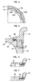
- FIG. 1 A case where the structure of item (i) above is provided at an axially inner portion of the rim is shown in FIG. 1 .
- the coupling portion 15 is provided at each of an axially inner portion and an axially outer portion of the rim.
- the coupling portion 15 provided at the axially inner portion of the rim cannot be viewed obstructed by the disk 12.
- FIGs. 2 and 3 A case where the structure of item (ii) above is provided at an axially outer portion of the rim is shown in FIGs. 2 and 3 .
- the disk surface 19 and the back surface 20 of the side ring are constructed to intersect each other with an angle, and the end of the contact surfaces 18 is positioned at a boundary between the disk surface 19 and the back surface 20 of the side ring having an angle therebetween.
- two vertical-load supporting portions 21 and 22 are provided with a relatively large distance provided between the two supporting portions 21 and 22.
- a groove 25 where a seal ring (O-ring) 24 is fitted is formed in either one of the rim main portion 13 and the side ring 14, and an undercut 26 is formed in the other of the rim main portion 13 and the side ring 14 where the groove 25 is not formed, so that at a position where the side ring is rotated, the O-ring 24 does not contact the side ring.
- An axial clearance (an axial gap) 27 is provided between the protrusion 15b of the rim main portion 13 and the protrusion 15b of the side ring 14 so that the side ring 14 can move in the axial direction of the wheel between a first position to rotate the side ring 14 and a second position to lock the side ring 14 and to obtain sealing.
- the coupling portion 15 is provided in an axially inner portion of the rim (at a right-and-left direction of the vehicle), the gap 16 between the rim main portion 13 and the side ring 14 and a step 23 at a coupling portion between the rim main portion and the side ring cannot be viewed from outside in the axial direction of the wheel, so that an appearance of the wheel can be made good. Further, even when a side surface of the wheel happens to contact a boundary pavement step of a road, the coupling portion 15 positioned at the axially inner portion of the rim does not suffer or is unlikely to suffer a damage.
- the gap 16 is hard to be viewed from outside in the axial direction of the wheel, so that an appearance of the wheel can be made good.
- the gap 16 is non-conspicuous.
- the gap 16 is non-conspicuous.
- a seal ring groove 25 for fitting a seal ring (O-ring) 24 therein is formed, and in the other of the rim main portion 13 and the side ring 14, an undercut 26 is formed so that at a position where the side ring 14 is rotated the seal ring 24 does not contact the other of the rim main portion and the side ring, a force for rotating the side ring 14 about an axis of the wheel can be small, maintaining the sealing ability good.
- the laterally installing wheel 10 according to the present invention can be utilized for improving an external appearance of the laterally installing wheel where at least one of rim flanges is divided from the rim main portion.
Landscapes
- Engineering & Computer Science (AREA)
- Mechanical Engineering (AREA)
- Tires In General (AREA)
- Transplanting Machines (AREA)
Claims (4)
- Rad zur seitlichen Anbringung, einschließlich einer Felge, wobei ein Felgenhauptabschnitt (13) und ein Seitenring (14) lösbar durch einen Verbindungsabschnitt (15) des Felgenhauptabschnitts und des Seitenrings miteinander verbunden sind, wodurch ermöglicht wird, dass der Reifen seitlich an dem Felgenhauptabschnitt angebracht wird,
wobei der Verbindungsabschnitt so ausgebildet ist, dass ein Abstand (16) zwischen dem Felgenhauptabschnitt und dem Seitenring von Außen in axialer Richtung des Rads nicht oder schwer sichtbar ist,
wobei im zusammengefügten Zustand bei Verwendung die Reifenwulst auf der Seite des Rads, wo sich der Seitenring befindet, auf dem Seitenring sitzt, und
wobei ein Element von Felgenhauptabschnitt und Seitenring eine Dichtungsringnut (25) und einen Dichtungsring (24) in der Dichtungsringnut aufweist,
wobei der Felgenhauptabschnitt und der Seitenring zwischen einer ersten Position, in der der Seitenring in einer axialen Richtung der Felge in den Felgenhauptabschnitt eingebracht wird, und einer zweiten Position, in der der Seitenring so rotiert wird, dass ein Vorsprung (15a) des Felgenhauptabschnitts und ein Vorsprung (15b) des Seitenrings miteinander in axialer Richtung der Felge in Eingriff gelangen, wodurch der Seitenring in axialer Richtung nicht von dem Felgenhauptabschnitt abgenommen werden kann, in Bezug aufeinander verdreht werden können,
dadurch gekennzeichnet, dass in dem anderen Element von Felgenhauptabschnitt und Seitenring, jenem anderen, das keine Dichtungsringnut aufweist, eine Hinterschneidung (26) so ausgebildet ist, dass der Dichtungsring in der ersten Position, in der der Seitenring in Bezug auf den Felgenhauptabschnitt verdreht wird, das andere Element von Felgenhauptabschnitt und Seitenring nicht berührt. - Rad mit seitlicher Anbringung nach Anspruch 1, worin Kontaktflächen (18) des Felgenhauptabschnitts und des Seitenrings in eine horizontale Richtung ausgerichtet sind.
- Rad mit seitlicher Anbringung nach Anspruch 2, worin eine Oberfläche einer Scheibe (19) und eine hintere Fläche (20) des Seitenrings einander in einem Winkel schneiden und ein Ende der Kontaktflächen von Felgenhauptabschnitt und Seitenring an einer Grenze zwischen der Oberfläche einer Scheibe und der hinteren Fläche des Seitenrings angeordnet ist.
- Rad mit seitlicher Anbringung nach Anspruch 1, worin zwei vertikale Lastträgerabschnitte an einem Verbindungsabschnitt zwischen dem Felgenhauptabschnitt und dem Seitenring in axialer Richtung des Rads bereitgestellt sind.
Applications Claiming Priority (2)
| Application Number | Priority Date | Filing Date | Title |
|---|---|---|---|
| JP2003166489A JP4190356B2 (ja) | 2003-06-11 | 2003-06-11 | 横装填ホイール |
| PCT/JP2003/009982 WO2004110787A1 (ja) | 2003-06-11 | 2003-08-06 | 横装填ホイール |
Publications (4)
| Publication Number | Publication Date |
|---|---|
| EP1632363A1 EP1632363A1 (de) | 2006-03-08 |
| EP1632363A4 EP1632363A4 (de) | 2007-10-03 |
| EP1632363B1 true EP1632363B1 (de) | 2012-01-25 |
| EP1632363B8 EP1632363B8 (de) | 2012-03-21 |
Family
ID=33549259
Family Applications (1)
| Application Number | Title | Priority Date | Filing Date |
|---|---|---|---|
| EP03817260A Expired - Lifetime EP1632363B8 (de) | 2003-06-11 | 2003-08-06 | Seitlich eingebautes rad |
Country Status (6)
| Country | Link |
|---|---|
| US (1) | US7284584B2 (de) |
| EP (1) | EP1632363B8 (de) |
| JP (1) | JP4190356B2 (de) |
| KR (1) | KR100817819B1 (de) |
| CN (1) | CN100443314C (de) |
| WO (1) | WO2004110787A1 (de) |
Families Citing this family (15)
| Publication number | Priority date | Publication date | Assignee | Title |
|---|---|---|---|---|
| DE102007049767A1 (de) * | 2007-10-17 | 2009-04-23 | Agco Gmbh | Mehrteilige Felge |
| US8636048B2 (en) | 2008-05-29 | 2014-01-28 | James R. Carawan | Tire run-flat removal and installation machine |
| US20120104836A1 (en) * | 2010-10-31 | 2012-05-03 | Liao Ho-Yo | Structure of fast-screwed two-piece type wheel rim |
| US20120248855A1 (en) * | 2011-04-04 | 2012-10-04 | Honeywell International Inc. | Anti-rotation interlocking inboard and outboard wheel components |
| AU2013318229B2 (en) | 2012-09-20 | 2017-07-06 | Gkn Armstrong Wheels, Inc. | Lock ring spreader |
| US9662936B2 (en) | 2012-12-12 | 2017-05-30 | Goodrich Corporation | Threaded side rim or threaded lock ring wheel for use with low-pressure or non-pneumatic tires |
| CA2938672C (en) * | 2014-02-04 | 2017-06-27 | Alcoa Inc. | Wheel assembly |
| US9925827B2 (en) * | 2015-03-27 | 2018-03-27 | Goodrich Corporation | Aircraft wheel release channel |
| US9815327B2 (en) * | 2015-09-03 | 2017-11-14 | National Taipei University Of Technology | Quick release apparatus for bicycle tire or tube |
| WO2017116408A1 (en) * | 2015-12-29 | 2017-07-06 | Compagnie Generale Des Etablissements Michelin | Pneumatic tire with non-annular protective sheet for bead area and methods for use with wheel having gap in rim-flange |
| US10226962B2 (en) | 2016-12-05 | 2019-03-12 | Honeywelll International Inc. | Vehicle wheel including antirotation plate |
| KR102213605B1 (ko) * | 2017-07-05 | 2021-02-08 | 한국자동차연구원 | 차량용 휠장치 |
| FR3069484A1 (fr) * | 2017-07-27 | 2019-02-01 | Compagnie Generale Des Etablissements Michelin | Roue pour le montage d'un dispositif de type pneumatique pour vehicule |
| US20190366765A1 (en) * | 2018-05-29 | 2019-12-05 | Ching-Fu Chuang | Wheel rim |
| EP4041572A1 (de) | 2019-10-10 | 2022-08-17 | Hutchinson S.A. | Radfelge mit gewindeverbindung |
Family Cites Families (32)
| Publication number | Priority date | Publication date | Assignee | Title |
|---|---|---|---|---|
| US1516018A (en) * | 1919-10-18 | 1924-11-18 | Bruce P Kitchell | Wheel for motor vehicles |
| US1710614A (en) * | 1925-04-01 | 1929-04-23 | Furrer Albert | Tire rim |
| US1936745A (en) * | 1931-12-24 | 1933-11-28 | Areson Nels | Pneumatic tire rim |
| GB406867A (en) * | 1932-03-09 | 1934-03-08 | Emil Zipper | Improvements in and relating to wheels for power-driven vehicles and the like with detachable rims |
| US2427634A (en) * | 1945-01-09 | 1947-09-16 | Budd Co | Heavy-duty wheel rim |
| US2496256A (en) * | 1948-03-09 | 1950-02-07 | Cecil E Bassett | Separable rim |
| US2636535A (en) * | 1951-09-12 | 1953-04-28 | Jerry J Gaquinto | Vehicle wheel |
| US2675048A (en) * | 1952-06-06 | 1954-04-13 | Louis J Ebert | Separable and demountable tire rim |
| GB951605A (en) * | 1959-06-18 | 1964-03-04 | Dunlop Rubber Co | Wheels for pneumatic tyres |
| DE1243040B (de) * | 1961-09-04 | 1967-06-22 | Giulio Gianetti Saronno Societ | Felge fuer Fahrzeugraeder |
| US3494404A (en) * | 1967-07-14 | 1970-02-10 | Thompson Wendell L | Wheel for supporting a tire |
| JPS46101Y1 (de) | 1968-02-24 | 1971-01-06 | ||
| FR2293324A1 (fr) * | 1974-12-03 | 1976-07-02 | Michelin & Cie | Perfectionnements aux jantes pour roues de vehicules |
| US4175606A (en) * | 1977-04-28 | 1979-11-27 | Clifford E. Bailey | Assembly for mounting tubeless tires |
| JPS5410601U (de) * | 1977-06-24 | 1979-01-24 | ||
| JPS585606Y2 (ja) * | 1978-08-15 | 1983-01-31 | オ−ツタイヤ株式会社 | チユ−ブレスタイヤ用車輪 |
| JPS5528578A (en) | 1978-08-22 | 1980-02-29 | Nippon Telegr & Teleph Corp <Ntt> | Memory ic driving system |
| JPS5827121B2 (ja) * | 1979-09-20 | 1983-06-07 | ベ−ベ−エス−クラフトフア−ツオイグテクニク・ゲゼルシヤフト・ミツト・ベシユレンクテル・ハフツンク・ウント・コンパニ−・コマンジツトゲゼルシヤフト | 相互に堅く接合された二つの部分から成る自動車車輪 |
| JPS57158102A (en) * | 1981-03-25 | 1982-09-29 | Topy Ind Ltd | Wheel rim |
| US4512382A (en) * | 1982-06-04 | 1985-04-23 | Gibson Donald L | Indexing and locking assembly for multi-piece truck rims |
| US4574859A (en) * | 1983-01-17 | 1986-03-11 | The Goodyear Tire & Rubber Company | Rim assembly |
| CH669154A5 (de) * | 1986-03-14 | 1989-02-28 | Fischer Ag Georg | Scheibenrad. |
| US4706723A (en) * | 1986-04-14 | 1987-11-17 | Unit Rig & Equipment Company | Rim for heavy, off-road vehicles |
| JPS6328702A (ja) * | 1986-07-21 | 1988-02-06 | Takaaki Aoki | 自動車用の2ピ−ス型ホイ−ルとその製造法 |
| ZA897032B (en) * | 1988-10-20 | 1990-06-27 | Komatsu Dresser Co | Rotary forged curved side flange for five piece rims |
| JPH02182507A (ja) * | 1989-01-05 | 1990-07-17 | Sumitomo Rubber Ind Ltd | ラジアルタイヤとリムの組立体 |
| US5259430A (en) * | 1991-11-27 | 1993-11-09 | Aircraft Braking Systems Corporation | Configuration for demountable wheel rim flange/split lockring assemblies |
| TW245691B (de) * | 1993-07-28 | 1995-04-21 | Janus Jonny | |
| JP2001191702A (ja) * | 2000-01-12 | 2001-07-17 | Topy Ind Ltd | ディスクホイール |
| JP4064034B2 (ja) | 2000-02-28 | 2008-03-19 | トピー工業株式会社 | ドロップレスリム |
| JP2001277805A (ja) * | 2000-03-30 | 2001-10-10 | Topy Ind Ltd | 操安性向上ホイール |
| JP2003312204A (ja) * | 2002-04-18 | 2003-11-06 | Topy Ind Ltd | 弾性ホイール |
-
2003
- 2003-06-11 JP JP2003166489A patent/JP4190356B2/ja not_active Expired - Fee Related
- 2003-08-06 CN CNB03826594XA patent/CN100443314C/zh not_active Expired - Fee Related
- 2003-08-06 KR KR1020057022382A patent/KR100817819B1/ko not_active Expired - Fee Related
- 2003-08-06 EP EP03817260A patent/EP1632363B8/de not_active Expired - Lifetime
- 2003-08-06 WO PCT/JP2003/009982 patent/WO2004110787A1/ja not_active Ceased
-
2005
- 2005-12-09 US US11/297,323 patent/US7284584B2/en not_active Expired - Fee Related
Also Published As
| Publication number | Publication date |
|---|---|
| KR20060016091A (ko) | 2006-02-21 |
| JP2005001489A (ja) | 2005-01-06 |
| KR100817819B1 (ko) | 2008-03-31 |
| CN100443314C (zh) | 2008-12-17 |
| EP1632363A1 (de) | 2006-03-08 |
| US7284584B2 (en) | 2007-10-23 |
| EP1632363A4 (de) | 2007-10-03 |
| EP1632363B8 (de) | 2012-03-21 |
| JP4190356B2 (ja) | 2008-12-03 |
| CN1787924A (zh) | 2006-06-14 |
| US20060086447A1 (en) | 2006-04-27 |
| WO2004110787A1 (ja) | 2004-12-23 |
Similar Documents
| Publication | Publication Date | Title |
|---|---|---|
| EP1632363B1 (de) | Seitlich eingebautes rad | |
| CN105377630B (zh) | 用于转动连接第一和第二铰接臂的旋转接头系统及配备该旋转接头系统的反射镜支架和反射镜 | |
| JPWO2003033303A1 (ja) | 車両用バックミラー | |
| JP2000025422A (ja) | ハブキャップを備えたタイヤ/ホイ―ル装着組立体 | |
| JP2000025422A5 (de) | ||
| CN111959193B (zh) | 一种车轮轴承组件及车辆 | |
| CN103287209A (zh) | 密封体、设备及方法 | |
| JP2005335546A (ja) | 車両用サンバイザ | |
| WO2022048597A1 (zh) | 壳体及具有该壳体的平衡车 | |
| JP4064034B2 (ja) | ドロップレスリム | |
| CN217074234U (zh) | 摄像头安装结构及车辆 | |
| GB2388158A (en) | Vehicle door with interference fit mounting component for pulley | |
| CN211918274U (zh) | 差速箱体主体和通用差速箱体组件 | |
| JPH1148703A (ja) | ディスクホイール | |
| CN223686257U (zh) | 中空脚轮 | |
| CN119037543B (zh) | 一种隔离组件、转向单元及车辆 | |
| CN110406365B (zh) | 一种电动轮汽车用前转接盘 | |
| CN216951416U (zh) | 一种法兰盘与传动轴的连接锁止机构 | |
| JP3156426B2 (ja) | 前後のブレーキサイズの異なる車両の車輪誤組付防止構造 | |
| JP4255022B2 (ja) | 車両用ホイールの横装填式リム構造およびホイールアッセンブリの組立方法 | |
| JP2008524520A (ja) | 自動車のトランスミッションを保護するためのマルチローブソケット | |
| WO1999021726A1 (en) | Unitary light alloy wheel for vehicles | |
| JPS61235207A (ja) | 車両用ホイ−ル | |
| JPH0222322Y2 (de) | ||
| JP2001191702A (ja) | ディスクホイール |
Legal Events
| Date | Code | Title | Description |
|---|---|---|---|
| PUAI | Public reference made under article 153(3) epc to a published international application that has entered the european phase |
Free format text: ORIGINAL CODE: 0009012 |
|
| 17P | Request for examination filed |
Effective date: 20051214 |
|
| AK | Designated contracting states |
Kind code of ref document: A1 Designated state(s): DE FR GB |
|
| DAX | Request for extension of the european patent (deleted) | ||
| RBV | Designated contracting states (corrected) |
Designated state(s): DE FR GB |
|
| A4 | Supplementary search report drawn up and despatched |
Effective date: 20070905 |
|
| 17Q | First examination report despatched |
Effective date: 20100212 |
|
| GRAP | Despatch of communication of intention to grant a patent |
Free format text: ORIGINAL CODE: EPIDOSNIGR1 |
|
| GRAS | Grant fee paid |
Free format text: ORIGINAL CODE: EPIDOSNIGR3 |
|
| GRAA | (expected) grant |
Free format text: ORIGINAL CODE: 0009210 |
|
| AK | Designated contracting states |
Kind code of ref document: B1 Designated state(s): DE FR GB |
|
| REG | Reference to a national code |
Ref country code: GB Ref legal event code: FG4D |
|
| RBV | Designated contracting states (corrected) |
Designated state(s): DE FR |
|
| REG | Reference to a national code |
Ref country code: DE Ref legal event code: R096 Ref document number: 60339864 Country of ref document: DE Effective date: 20120329 |
|
| PLBE | No opposition filed within time limit |
Free format text: ORIGINAL CODE: 0009261 |
|
| STAA | Information on the status of an ep patent application or granted ep patent |
Free format text: STATUS: NO OPPOSITION FILED WITHIN TIME LIMIT |
|
| 26N | No opposition filed |
Effective date: 20121026 |
|
| REG | Reference to a national code |
Ref country code: DE Ref legal event code: R097 Ref document number: 60339864 Country of ref document: DE Effective date: 20121026 |
|
| REG | Reference to a national code |
Ref country code: FR Ref legal event code: ST Effective date: 20130430 |
|
| PG25 | Lapsed in a contracting state [announced via postgrant information from national office to epo] |
Ref country code: FR Free format text: LAPSE BECAUSE OF NON-PAYMENT OF DUE FEES Effective date: 20120831 |
|
| PGFP | Annual fee paid to national office [announced via postgrant information from national office to epo] |
Ref country code: DE Payment date: 20130827 Year of fee payment: 11 |
|
| REG | Reference to a national code |
Ref country code: DE Ref legal event code: R119 Ref document number: 60339864 Country of ref document: DE |
|
| REG | Reference to a national code |
Ref country code: DE Ref legal event code: R119 Ref document number: 60339864 Country of ref document: DE Effective date: 20150303 |
|
| PG25 | Lapsed in a contracting state [announced via postgrant information from national office to epo] |
Ref country code: DE Free format text: LAPSE BECAUSE OF NON-PAYMENT OF DUE FEES Effective date: 20150303 |