EP1632336A1 - Reifen und Verfahren zu seiner Herstellung - Google Patents
Reifen und Verfahren zu seiner Herstellung Download PDFInfo
- Publication number
- EP1632336A1 EP1632336A1 EP05017232A EP05017232A EP1632336A1 EP 1632336 A1 EP1632336 A1 EP 1632336A1 EP 05017232 A EP05017232 A EP 05017232A EP 05017232 A EP05017232 A EP 05017232A EP 1632336 A1 EP1632336 A1 EP 1632336A1
- Authority
- EP
- European Patent Office
- Prior art keywords
- winding
- strip material
- rubber strip
- tire
- circumferential direction
- Prior art date
- Legal status (The legal status is an assumption and is not a legal conclusion. Google has not performed a legal analysis and makes no representation as to the accuracy of the status listed.)
- Withdrawn
Links
- 238000004519 manufacturing process Methods 0.000 title claims description 7
- 238000004804 winding Methods 0.000 claims abstract description 282
- 229920001971 elastomer Polymers 0.000 claims abstract description 249
- 239000005060 rubber Substances 0.000 claims abstract description 249
- 239000000463 material Substances 0.000 claims abstract description 193
- 238000000034 method Methods 0.000 claims description 18
- 239000011295 pitch Substances 0.000 description 22
- 230000001965 increasing effect Effects 0.000 description 9
- 238000006073 displacement reaction Methods 0.000 description 7
- 230000002411 adverse Effects 0.000 description 5
- 230000002349 favourable effect Effects 0.000 description 5
- 230000003247 decreasing effect Effects 0.000 description 4
- 238000001125 extrusion Methods 0.000 description 3
- 238000005520 cutting process Methods 0.000 description 2
- 238000010586 diagram Methods 0.000 description 2
- 230000003014 reinforcing effect Effects 0.000 description 2
- 238000010276 construction Methods 0.000 description 1
- 230000000694 effects Effects 0.000 description 1
- 230000002708 enhancing effect Effects 0.000 description 1
- 238000003475 lamination Methods 0.000 description 1
Images



Classifications
-
- B—PERFORMING OPERATIONS; TRANSPORTING
- B29—WORKING OF PLASTICS; WORKING OF SUBSTANCES IN A PLASTIC STATE IN GENERAL
- B29D—PRODUCING PARTICULAR ARTICLES FROM PLASTICS OR FROM SUBSTANCES IN A PLASTIC STATE
- B29D30/00—Producing pneumatic or solid tyres or parts thereof
- B29D30/06—Pneumatic tyres or parts thereof (e.g. produced by casting, moulding, compression moulding, injection moulding, centrifugal casting)
- B29D30/52—Unvulcanised treads, e.g. on used tyres; Retreading
- B29D30/58—Applying bands of rubber treads, i.e. applying camel backs
- B29D30/60—Applying bands of rubber treads, i.e. applying camel backs by winding narrow strips
-
- B—PERFORMING OPERATIONS; TRANSPORTING
- B29—WORKING OF PLASTICS; WORKING OF SUBSTANCES IN A PLASTIC STATE IN GENERAL
- B29D—PRODUCING PARTICULAR ARTICLES FROM PLASTICS OR FROM SUBSTANCES IN A PLASTIC STATE
- B29D30/00—Producing pneumatic or solid tyres or parts thereof
- B29D30/06—Pneumatic tyres or parts thereof (e.g. produced by casting, moulding, compression moulding, injection moulding, centrifugal casting)
- B29D30/08—Building tyres
- B29D30/20—Building tyres by the flat-tyre method, i.e. building on cylindrical drums
- B29D30/30—Applying the layers; Guiding or stretching the layers during application
-
- Y—GENERAL TAGGING OF NEW TECHNOLOGICAL DEVELOPMENTS; GENERAL TAGGING OF CROSS-SECTIONAL TECHNOLOGIES SPANNING OVER SEVERAL SECTIONS OF THE IPC; TECHNICAL SUBJECTS COVERED BY FORMER USPC CROSS-REFERENCE ART COLLECTIONS [XRACs] AND DIGESTS
- Y10—TECHNICAL SUBJECTS COVERED BY FORMER USPC
- Y10T—TECHNICAL SUBJECTS COVERED BY FORMER US CLASSIFICATION
- Y10T152/00—Resilient tires and wheels
- Y10T152/10—Tires, resilient
- Y10T152/10495—Pneumatic tire or inner tube
Definitions
- the present invention relates to a tire which is constituted from a plurality of tire rubbers and a building method of the tire.
- a tire is constituted from a plurality of types of rubber used for tires.
- respective portions consisting of an inner liner rubber portion 2, a tread rubber portion 3, side wall rubber portions 4, rim strip rubber portions 5 and the like are formed of rubber types with characteristics respectively required.
- These rubber members are combined with tire reinforcing members such as a carcass 6 and a belt 7 to construct a tire.
- rubber material is continuously extruded from extruders using dies with the cross-sectional shapes of the desired rubber members, and thereafter the extruded materials are cut into predetermined sizes.
- the tire is assembled by sequentially adhering the rubber members on a rotary support body such as a building drum.
- JP-A-1997-29858 there has been proposed a method in which an unvulcanized rubber strip material which is formed into a ribbon shape by extrusion is wound around a rotary support body such as a building drum in a spirally overlapping manner along the circumference of the tire to build a rubber member having a given cross-sectional shape.
- the inventors of the present inventions also have proposed a method in which the rubber strip material is wound with the overlapping amount in the tire widthwise direction of the rubber strip material limited to a value within a fixed range (1/2 to 1/5 of the width of the rubber strip material) (JP-A-2002-205512) .
- the rubber member having the given shape is built with the displacement between the winding starting position and the winding finishing position of the rubber strip material in the circumferential direction of the tire set within a range of 0 to 5mm.
- the winding mode basically, the first complete winding of the rubber strip material on the winding starting side and the last winding of the rubber strip material on the winding finishing side are wound in parallel in the tire circumferential direction orthogonal to the tire widthwise direction, while other winding portions of the rubber strip material consisting of the second winding and succeeding windings of the rubber strip material are wound in a spiral manner so as to advance one pitch in the widthwise direction per one winding or one rotation.
- the first winding and the last winding of the rubber strip material are wound parallel to the tire circumferential direction. Accordingly, extra rubber portions which project sideward from both of left-and-right-side end portions as shown in the patent literature 1 are not formed and hence, the cutting treatment after winding becomes unnecessary.
- the amount of wound rubber is increased, thus adversely influencing the tire uniformity.
- Fig. 8 is a developed plan view which schematically shows several windings of the rubber strip material 101 on the winding starting side and several windings of the rubber strip material 101 on the winding finishing side with respect to the winding state of the rubber strip material 101.
- the first winding of the rubber strip material 101 on the winding starting side is indicated by M 1
- the second winding of the rubber strip material 101 is indicated by M 2
- the third winding of the rubber strip material 101 is indicated by M 3
- ... the (n-1) th winding of the rubber strip material 101 is indicated by M n-1
- the last nth winding of the rubber strip material 101 is indicated by M n . That is, Fig.
- the ideal overlapping of the rubber strip material 101 is such that the first 1/2 width of the first winding has one layer, the second winding M 2 which overlaps the remaining 1/2 width of the first winding and succeeding windings have two layers, and the last 1/2 width of the last nth winding M n has one layer.
- the spiral second winding M 2 overlaps the first 1/2 width portion of the first winding M 1 , building a two-layer portion Q1 (hatched lines). Further, an overlapping portion Q2 (lattice pattern) having three layers is generated on the remaining 1/2 width portion of the first winding M 1 due to the spiral winding of the third winding M 3 .
- Similar overlapping portions are generated with respect to the nth winding M n and the (n-1)th winding M n-1 of the rubber strip material 101 on the winding finishing side.
- the overlapping portion Q1 having two layers at a portion where one layer is sufficient and the overlapping portion Q2 having three layers at a portion where two layers are sufficient extend in an elongated manner in the circumferential direction substantially over the full length due to the spiral winding and hence, the excess rubber amount exceeding the ideal amount at the undesired overlapping portions is increased, thus adversely influencing the weight balance of the tire and the uniformity of the rubber strip materials, and thus having adverse influence on the tire uniformity.
- the present invention has been made in view of such circumstances and it is an object of the present invention to provide a tire which is constituted by including a plurality of tire rubber members and, in building at least one rubber member by overlapping a ribbon-shaped rubber strip material, can minimize undesired overlapping portions and thus exhibit favorable weight balance and uniformity whereby favorable tire uniformity characteristics can be attained, and a tire construction method for obtaining such a tire.
- a tire which is constituted by including a plurality of rubber members for tires, in which at least one rubber member is built by overlapping a portion of a ribbon-like rubber strip material along the tire circumferential direction, wherein the rubber strip material is built such that the first winding of the rubber strip material on a winding starting side is wound in the tire circumferential direction which is orthogonal to the tire-widthwise direction from a winding starting position, a second winding and succeeding windings of the rubber strip material are wound in an inclined manner with respect to the tire circumferential direction within a given portion ("inclined region") along the tire circumference, imparting a given pitch in the tire widthwise direction and are wound in the tire circumferential direction orthogonal to the tire widthwise direction in the regions other than the inclined region, and the final winding on the winding finishing side is wound in the tire circumferential direction orthogonal to the tire widthwise direction over the inclined region without being inclined and thus is terminated.
- the rubber strip material is built such that the first winding of the rubber
- At least one rubber member which is formed by winding the rubber strip material is configured such that, due to the winding mode, in addition to the winding of the first winding on the winding starting side and the winding of final winding in the tire circumferential direction, the inclined region for imparting pitch to every winding from the second winding onward is limited to one portion in the tire circumferential direction, and the portions other than the inclined region are wound in the tire circumferential direction. That is, windings in the portions other than the inclined region are arranged parallel with the tire circumferential direction.
- the rubber strip material is wound so that the winding finishing position is shifted away from the winding starting position in the winding direction, and the length of the inclined regions is limited to less than the shift between the winding starting position and the winding finishing position. Accordingly, by decreasing the length of the inclined region in the tire circumferential direction, the positional displacement between the winding starting position and the winding finishing position can be decreased and hence, the weight balance of the tire can be further enhanced, thus increasing the tire uniformity.
- the inclination angle of the rubber strip material with respect to the tire circumferential direction in the inclined region is set to 45° or below, and the length in the tire circumferential direction of the inclined region is not smaller than 1/5 times of and not more than 5 times greater than the width of the rubber strip material.
- the length in the tire circumferential direction of the inclined region exceeds a value which is 5 times the width of the rubber strip material, the undesired overlapping portion is increased depending on the width of the rubber strip material, and hence, it is difficult to obtain the weight-balancing and uniformity enhancing effect. Accordingly, it is desirable to set the length in the tire circumferential direction of the inclined region to the value which falls in the above range.
- a method for manufacturing a tire which is constituted by including a plurality of above-mentioned rubber members for tires.
- the method includes a step in which at least one rubber strip material is built by winding a ribbon-like rubber strip material so that a portion of the rubber strip material overlaps itself in the tire circumferential direction.
- the first winding of the rubber strip material is wound in the tire circumferential direction which is orthogonal to the tire widthwise direction from a set winding starting position, and subsequently a second and succeeding windings of the rubber strip material are wound in an inclined manner within one portion along the tire circumference to impart a given pitch to the rubber strip material in the tire widthwise direction for every winding, and the rubber strip material is wound in the tire circumferential direction orthogonal to the tire widthwise direction in portions other than the inclined region, and a final winding on the winding finishing side going over the inclined region is wound in the tire circumferential direction orthogonal to the tire widthwise direction and is terminated without being inclined.
- the length in the tire circumferential direction of the inclined region is limited to less than the positional displacement between the winding starting position and the winding finishing position of the rubber strip material and hence, by setting the length of the inclined region to a small value, the positional displacement between the winding starting position and the winding finishing position also becomes small, whereby the weight balance and the uniformity of the rubber members can be enhanced and the uniformity of the tire can also be improved.
- the rubber strip material is supplied to a given rotary support body and is wound due to the rotation of a rotary support body and, only at rotational angle portions corresponding to the inclined regions of the second winding and succeeding windings, the unit for supplying the rubber strip material is controlled to be moved in the widthwise direction relative to the rotary support body, thus inclining the rubber strip material while winding the rubber strip material, to impart a given pitch in the widthwise direction. Accordingly, it is possible to automate the winding state in which the inclined region of winding of the rubber strip material is set only at one portion along the tire circumference, and hence the productivity is enhanced.
- the winding of the rubber strip material is performed such that the inclination angle of the inclined portion of the rubber strip material with respect to the tire circumferential direction is set to 45° or less. Due to such a winding operation, the deformation of the rubber strip material at the boundary between the region wound in the tire circumferential direction and the inclined region does not become excessively large during the winding of the rubber strip material whereby, it is possible to smoothly perform the building-by-winding even though only one portion along the tire circumference is inclined.
- the length in the tire circumferential direction of the inclined region is set to 1/5 or less of the length of one winding the rubber strip material. Due to such a constitution, the weight balance and the uniformity can be favorably maintained.
- the width of the rubber strip material Assuming the width of the rubber strip material to be 5 to 50mm and the overlapping margin of the rubber strip material to be 4/5 to 1/5 of the width of the rubber strip material, it is appropriate that the inclination angle of the rubber strip material with respect to the tire circumferential direction in the inclined region is 45° or less and the length of the inclined region in the tire circumferential direction is between 1/5 and 5 times the width of the rubber strip material. Due to such a limitation, it is possible to build various kinds of rubber members for tires by winding ribbon-shaped rubber strip material without giving rise to any problems.
- the tire and the tire building method of the present invention which forms the rubber member for a tire by winding the ribbon-like rubber strip material, as the winding mode of the rubber strip material, in addition to the first winding on the winding starting side and the final winding which are oriented in the tire circumferential direction, with respect to the winding portions of the second and succeeding windings, for every winding, the rubber strip material is wound in an inclined manner to impart a given pitch within one portion along the tire circumference, and is wound parallel to the tire circumferential direction in all other portions.
- the present invention can easily cope with the change of the width, the thickness, the overlapping margin and the like of the rubber strip material whereby the present invention is applicable to the building of rubber members having various shapes.
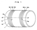
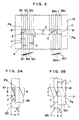
- Fig. 1 and Fig. 2 are schematic views for explaining the winding state of a ribbon-like rubber strip material 1 which is supplied to a rotary support body 20 such a building drum or the like according to the present invention, wherein Fig. 1 is a schematic perspective view, Fig. 2 is a schematic front view. Fig. 3A and Fig. 3B are views showing a portion of a winding starting end and a portion of a winding finishing end shown in Fig. 2.
- the basic constitution a tire T comprises a plurality of rubber members including an inner liner rubber portion 2, a tread rubber portion 3, side wall rubber portions 4, and rim strip rubber portions 5. These rubber members are combined with tire reinforcing members such as a carcass 6, a belt 7 and the like to build the tire T.
- tire reinforcing members such as a carcass 6, a belt 7 and the like to build the tire T.
- Such a constitution is the same as that of a conventional tire.
- At least one of, preferably a plurality of, or all of the rubber members which constitute the tire T are built such that, in a building step of the tire manufacture, a ribbon-like rubber strip material 1 which is extruded in an elongated manner from a supply unit such as an extruder is wound in the tire circumferential direction with portions thereof overlapping each other.
- the cross-sectional shape of the rubber strip material 1 has a ribbon shape having a relatively flat cross-sectional shape whose thickness has a maximum value at the center portion and is gradually decreased from the center portion to both side ends; for example, an approximately crescent shape, an approximately flat triangular shape or a flat trapezoidal shape. It is practically preferable to use a relatively flat ribbon-like rubber strip material 1 which has a width of 5 to 50mm, a thickness at the center portion of 0.5 to 3.0mm, and a thickness at both side ends from 0.05 to 0.2mm.
- the winding mode of the rubber strip material 1 is explained in conjunction with the drawing, taking the case in which the rubber member which constitutes the inner liner rubber portion 2 in the tire T shown in Fig. 7, for example, is built by winding.
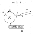
- Fig. 5 is a schematic view showing the basic constitution of a device for winding the rubber strip material 1. That is, Fig. 5 shows a case in which the supply unit 10 such as an extruder of the rubber strip material 1 is arranged to face the rotary support body 20 and the rubber strip material 1 which is supplied in a ribbon shape having a given cross-sectional shape from the supply unit 10 is directly supplied and wound around the rotary support body 20.
- the rotary support body 20 is rotatable on a shaft 20a and the rubber strip material 1 is wound along the tire circumferential direction as shown in Fig. 1 and Fig. 2 while rotating the rotary support body 20 in the direction K in Fig. 5.
- the first winding M 1 at the winding start side is wound in the tire circumferential direction orthogonal to the tire widthwise direction.
- the rubber strip material 1 is wound in an obliquely inclined manner with respect to the tire circumferential direction so as to impart a given pitch D corresponding to the overlapping margin B in the tire widthwise direction.
- the rubber strip material 1 is wound in parallel in the tire circumferential direction which is orthogonal to the tire widthwise direction at the position which has been shifted due to the above inclination.
- Symbol ⁇ in the drawing indicates the above-mentioned inclination angle.
- one winding is made which continues from the inclined region G, in the tire circumferential direction which is orthogonal to the tire widthwise direction and is terminated at the vicinity of the end of the inclined region G after overlapping the inclined region G without being inclined. That is, the rubber strip material 1 assumes a winding state in which the winding finishing position Pe is displaced from the winding starting position Ps in the winding direction, and the inclined region G is set within the range of this positional displacement. Accordingly, by decreasing the length E in the tire circumferential direction of the inclined region G, it is also possible to decrease the positional displacement between the winding starting position Ps and the winding finishing position Pe.
- the rotary support body 20 In winding the rubber strip material 1, the rotary support body 20 is rotated and, at the same time, to impart a given pitch D in the widthwise direction, in the rotational angle range corresponding to the inclined region G of the second winding and all the succeeding windings, the supply unit 10 shown in Fig. 5 is moved relative to the rotary support body 20 along the tire widthwise direction. Accordingly, either the supply unit 10 or the rotary support body 20 is moved along the tire widthwise direction. Due to this movement in the tire widthwise direction and the rotation of the rotary support body 20, it is possible to incline the rubber strip material 1 within the inclined region G.
- the inclination angle ⁇ can be suitably set by adjusting the rotational speed of the rotary support body 20, in particular the rotational speed in the circumferential direction of the outer periphery (a winding portion), and the speed of the movement in the widthwise direction.
- the respective conditions such as the width A, the overlapping margin B, the overlapping margin C within the inclined region G, the feed pitch D in the widthwise direction, the length E in the tire circumferential direction of the inclined regions G, the inclination angle ⁇ , and the like can be suitably set to enable the building by winding in conformity with the kind and the mode of the tire-use rubber member to be built, it is preferable in practice to set these conditions as follows.
- the inclination angle ⁇ is preferably set to 45° or less. That is, the larger the inclination angle ⁇ becomes, the larger the deformation at the connection between the portion oriented in the tire circumferential direction and the inclined portion in the winding of the rubber strip material 1. Particularly, when the inclination angle ⁇ exceeds 45°, the winding (lamination over this region) becomes difficult and hence, the object of the present invention cannot be achieved. Accordingly, irrespective of the width A, the overlapping margin B and other properties of the rubber strip material 1, it is preferable in practice to set the inclination angle ⁇ to 45° or less.
- the inclination angle ⁇ is set to a small value, in view of the relationship with the width A and the overlapping margin B of the rubber strip material 1, the length E of the inclined region G in the tire circumferential direction becomes large and hence, it is preferable to set the angle ⁇ such that the length E is not excessively increased.
- the length E in the tire circumferential direction of the inclined region G which allows the given feed pitch D by inclining the rubber strip material 1 can be determined in response to the width A and the overlapping margin B of the rubber strip material 1, the pitch D of winding in the widthwise direction and the inclination angle ⁇ , the larger the length E becomes, the more difficult it becomes to sufficiently reduce overlapping to have advantageous effect on the weight balance and the uniformity. Accordingly, the length E is limited to 1/5 or less of the length of one winding, preferably to 1/10 or less, and further preferably 5 times or less the width A of the rubber strip material 1. That is, it is preferable to set the length E as short as possible.
- the length E is set so that the inclination angle ⁇ does not exceed 45°.
- the overlapping margin B of the rubber strip material 1 is set to fall within a range of 4/5 to 1/5 of the width A of the rubber strip material 1.
- the feed pitch D in the widthwise direction that is, the feed amount in the widthwise direction in the inclined region G is set to 1/5 to 4/5 of the width A of the rubber strip material 1 corresponding to the overlapping margin B. That is, when the overlapping margin B is 4/5 of the width A, the pitch D becomes 1/5 of the width A.
- the overlapping margin B and the inclination angle ⁇ are determined based on the width A (5 to 50mm) of the rubber strip material 1 used, it is possible to determine the length E in the tire circumferential direction of the inclined regions G, the overlapping margin C within the inclined regions G, the feed pitch D in the widthwise direction and the like.
- the control of the overlapping margin B and the inclination angle ⁇ is performed by controlling the speed and the movement amount of relative movement in the tire widthwise direction between the supply unit 10 and the rotary support body 20 using the control device 30.
- Fig. 6A, Fig. 6B, Fig. 6C, Fig. 6D, Fig. 6E, Fig. 6F, Fig. 6G and Fig. 6H respectively show examples of combinations of various lengths E in the tire circumferential direction of the inclined region G, overlapping margins B of the rubber strip material 1 , feed pitches D and inclination angles ⁇ .
- Table 1 shows the combination examples of the width A, the overlapping margin B, the overlapping margin C in the inside of the inclined region G, the feed pitch D in the widthwise direction, the length E in the tire circumferential direction of the inclined regions G, the inclination angle ⁇ and the like of the rubber strip material 1.
- the overlap ratio B/A is the ratio of the overlapping margin B with respect to the width A of the rubber strip material 1.
- the types 3 to 6, 9, 10, 12, 13 in Table 1 respectively correspond to Fig. 6A, Fig. 6B, Fig. 6C, Fig. 6D, Fig. 6E, Fig. 6F, Fig. 6G and Fig. 6H.
- the first winding M 1 on the winding starting side and the last winding which continues from the inclined region G of the nth winding M n are wound in the tire circumferential direction, and the portions other than the inclined regions G of pitch feed windings starting from the second winding M 2 are wound in the tire circumferential direction. That is, all other portions except for the inclined regions G are wound in the tire circumferential direction.
- Fig. 4 shows a case in which the rubber strip material 1 is wound in a state that the overlapping margin B of the rubber strip material 1 is set to 1/2 of the width A of the rubber strip material 1 in the same manner as the case shown in Fig. 8. Circled numbers in portions of the drawing show the number of overlapping layers of rubber strip material in that portion.
- Fig. 4 shows a case in which the rubber strip material 1 is wound in a state that the overlapping margin B of the rubber strip material 1 is set to 1/2 of the width A of the rubber strip material 1 in the same manner as the case shown in Fig. 8.
- Circled numbers in portions of the drawing show the number of overlapping layers of rubber strip material in that portion.
- the first winding M 1 and the winding which continues from the inclined region G of the last nth winding M n are wound in the tire circumferential direction, and the other windings including the second winding M 2 are wound in an inclined manner only in the regions G along the tire circumference to impart pitch D and are in the tire circumferential direction at portions other than the inclined regions G.
- an overlapping portion Q1 (hatched in the diagram) having two layers is generated on the portion of the inclined region G due to the oblique winding of the next second winding M 2 and, further, at the other half of the first winding M 1 , an overlapping portion Q2 (grid in the diagram) having three layers is generated due to the oblique winding of the third winding M 3 . Further, the similar overlapping is generated at the nth winding M n on the winding finishing side and the (n-1) th winding M n-1 .
- the rubber member which constitutes the tread rubber portion 3 is constructed with a winding mode similar to the above-mentioned winding mode using two rubber strip materials for a first-layer and second-layer, it is preferable that there is a shift in the tire circumferential direction of 10° or more in the starting position for winding the first-layer (lower-layer) rubber strip material and the starting position for winding the second-layer (upper-layer) rubber strip material.
- the inclined region which is provided for imparting a given pitch in the widthwise direction is formed between the winding starting position and the winding finishing position, by setting the shift of the winding finishing position with respect to the winding starting position to 10° or more, the shift of the inclined regions of respective rubber members also becomes 10° or more.
- the explanation is made with respect to the case in which the building by winding of the rubber strip material 1 is performed by extruding the rubber strip material 1 from a supply unit 10 such as an extruder and supplying it to the rotary support body 20 such as a building drum simultaneously with the extrusion.
- the building by winding may be performed such that the rubber strip material is extruded in a step different from the winding step, the extruded rubber strip material is transferred to the site of the building-by-winding step, and the rubber strip material is continuously supplied to the rotary support body by way of a supply device.
- the present invention is suitably applicable to the case in which the tire is manufactured by building the rubber members for the tire, and the building is performed by winding the ribbon-like unvulcanized rubber strip materials in a spirally overlapping manner in the tire circumferential direction on a rotary support body such as a building drum.
Landscapes
- Engineering & Computer Science (AREA)
- Mechanical Engineering (AREA)
- Tyre Moulding (AREA)
- Tires In General (AREA)
Applications Claiming Priority (1)
| Application Number | Priority Date | Filing Date | Title |
|---|---|---|---|
| JP2004257764A JP2006069130A (ja) | 2004-09-03 | 2004-09-03 | タイヤ及びタイヤ成型方法 |
Publications (1)
| Publication Number | Publication Date |
|---|---|
| EP1632336A1 true EP1632336A1 (de) | 2006-03-08 |
Family
ID=35285260
Family Applications (1)
| Application Number | Title | Priority Date | Filing Date |
|---|---|---|---|
| EP05017232A Withdrawn EP1632336A1 (de) | 2004-09-03 | 2005-08-08 | Reifen und Verfahren zu seiner Herstellung |
Country Status (3)
| Country | Link |
|---|---|
| US (1) | US20060048873A1 (de) |
| EP (1) | EP1632336A1 (de) |
| JP (1) | JP2006069130A (de) |
Cited By (4)
| Publication number | Priority date | Publication date | Assignee | Title |
|---|---|---|---|---|
| WO2009068933A1 (en) * | 2007-11-28 | 2009-06-04 | Pirelli Tyre S.P.A. | Method for manufacturing tyres for vehicle wheels |
| CN103832215A (zh) * | 2012-11-22 | 2014-06-04 | 东洋橡胶工业株式会社 | 充气轮胎及其制造方法 |
| CN106696609A (zh) * | 2015-11-16 | 2017-05-24 | 东洋橡胶工业株式会社 | 轮胎 |
| CN111152491A (zh) * | 2019-12-30 | 2020-05-15 | 厦门洪海机械有限公司 | 一种快速计算多种冠带条工艺轮廓的方法 |
Families Citing this family (11)
| Publication number | Priority date | Publication date | Assignee | Title |
|---|---|---|---|---|
| JP4716365B2 (ja) * | 2005-10-17 | 2011-07-06 | 東洋ゴム工業株式会社 | 製造途中の空気入りタイヤの検査方法および検査装置 |
| JP4415966B2 (ja) * | 2006-04-03 | 2010-02-17 | 横浜ゴム株式会社 | 空気入りタイヤの製造方法 |
| JP5001798B2 (ja) * | 2007-11-19 | 2012-08-15 | 東洋ゴム工業株式会社 | タイヤ及びタイヤの成型方法 |
| FR2925923B1 (fr) * | 2007-12-28 | 2009-12-18 | Michelin Soc Tech | Procede et dispositif de fabrication d'un cable a deux couches du type gomme in situ |
| JP5066220B2 (ja) * | 2010-05-17 | 2012-11-07 | 住友ゴム工業株式会社 | 空気入りタイヤ及びその製造方法 |
| JP5841816B2 (ja) * | 2011-11-24 | 2016-01-13 | 東洋ゴム工業株式会社 | 空気入りタイヤの製造方法及び空気入りタイヤの製造装置 |
| JP5957430B2 (ja) * | 2013-10-24 | 2016-07-27 | 住友ゴム工業株式会社 | 空気入りタイヤ及びその製造方法 |
| JP6581890B2 (ja) * | 2015-12-03 | 2019-09-25 | Toyo Tire株式会社 | タイヤ及びタイヤの製造方法 |
| JP6938976B2 (ja) * | 2017-03-13 | 2021-09-22 | 住友ゴム工業株式会社 | ゴムストリップの巻回条件の計算方法及びタイヤの製造方法 |
| JP6971742B2 (ja) | 2017-09-25 | 2021-11-24 | Toyo Tire株式会社 | 空気入りタイヤ及びその製造方法 |
| NL2021086B1 (en) * | 2018-06-08 | 2019-12-13 | Vmi Holland Bv | Tire building method and tire building system, in particular for strip-winding |
Citations (5)
| Publication number | Priority date | Publication date | Assignee | Title |
|---|---|---|---|---|
| US3355339A (en) * | 1963-11-07 | 1967-11-28 | American Mach & Foundry | Method and apparatus for making solid tires |
| US4094354A (en) * | 1977-03-09 | 1978-06-13 | Uniroyal, Inc. | Breaker reinforcing tape for belted pneumatic tires, and tires made therefrom |
| JP2002205512A (ja) * | 2001-01-11 | 2002-07-23 | Toyo Tire & Rubber Co Ltd | タイヤ及びタイヤ製造方法 |
| EP1226926A1 (de) * | 1999-09-07 | 2002-07-31 | Fuji Seiko Co. Ltd. | Verfahren und vorrichtung zur herstellung von reifenlagen |
| JP2004130524A (ja) * | 2002-10-08 | 2004-04-30 | Toyo Tire & Rubber Co Ltd | トッピングシート成形装置及び成形方法 |
Family Cites Families (7)
| Publication number | Priority date | Publication date | Assignee | Title |
|---|---|---|---|---|
| US3251722A (en) * | 1962-05-01 | 1966-05-17 | Voit Rubber Corp | Method of automatically applying a variable thickness elastomeric layer on pneumatic tire casings |
| US3264162A (en) * | 1963-04-18 | 1966-08-02 | Voit Rubber Corp | Ribbon winding machine with indexable hubs |
| US4398583A (en) * | 1981-11-23 | 1983-08-16 | The Goodyear Tire & Rubber Company | Tire and method of applying sealant |
| US5178703A (en) * | 1990-10-24 | 1993-01-12 | Sumitomo Rubber Industries, Ltd. | Breaker with wound band |
| JP4420491B2 (ja) * | 1998-06-29 | 2010-02-24 | 株式会社ブリヂストン | タイヤ構成部材用ゴム材料の張付方法及び張付装置 |
| KR100850694B1 (ko) * | 2000-10-30 | 2008-08-06 | 스미도모 고무 고교 가부시기가이샤 | 공압 타이어 제조 방법 |
| JP4672858B2 (ja) * | 2000-12-14 | 2011-04-20 | 東洋ゴム工業株式会社 | タイヤ及びタイヤ製造方法 |
-
2004
- 2004-09-03 JP JP2004257764A patent/JP2006069130A/ja active Pending
-
2005
- 2005-07-14 US US11/181,353 patent/US20060048873A1/en not_active Abandoned
- 2005-08-08 EP EP05017232A patent/EP1632336A1/de not_active Withdrawn
Patent Citations (5)
| Publication number | Priority date | Publication date | Assignee | Title |
|---|---|---|---|---|
| US3355339A (en) * | 1963-11-07 | 1967-11-28 | American Mach & Foundry | Method and apparatus for making solid tires |
| US4094354A (en) * | 1977-03-09 | 1978-06-13 | Uniroyal, Inc. | Breaker reinforcing tape for belted pneumatic tires, and tires made therefrom |
| EP1226926A1 (de) * | 1999-09-07 | 2002-07-31 | Fuji Seiko Co. Ltd. | Verfahren und vorrichtung zur herstellung von reifenlagen |
| JP2002205512A (ja) * | 2001-01-11 | 2002-07-23 | Toyo Tire & Rubber Co Ltd | タイヤ及びタイヤ製造方法 |
| JP2004130524A (ja) * | 2002-10-08 | 2004-04-30 | Toyo Tire & Rubber Co Ltd | トッピングシート成形装置及び成形方法 |
Non-Patent Citations (2)
| Title |
|---|
| PATENT ABSTRACTS OF JAPAN vol. 2002, no. 11 6 November 2002 (2002-11-06) * |
| PATENT ABSTRACTS OF JAPAN vol. 2003, no. 12 5 December 2003 (2003-12-05) * |
Cited By (7)
| Publication number | Priority date | Publication date | Assignee | Title |
|---|---|---|---|---|
| WO2009068933A1 (en) * | 2007-11-28 | 2009-06-04 | Pirelli Tyre S.P.A. | Method for manufacturing tyres for vehicle wheels |
| CN103832215A (zh) * | 2012-11-22 | 2014-06-04 | 东洋橡胶工业株式会社 | 充气轮胎及其制造方法 |
| CN103832215B (zh) * | 2012-11-22 | 2016-04-13 | 东洋橡胶工业株式会社 | 充气轮胎及其制造方法 |
| CN106696609A (zh) * | 2015-11-16 | 2017-05-24 | 东洋橡胶工业株式会社 | 轮胎 |
| CN106696609B (zh) * | 2015-11-16 | 2018-06-26 | 东洋橡胶工业株式会社 | 轮胎 |
| CN111152491A (zh) * | 2019-12-30 | 2020-05-15 | 厦门洪海机械有限公司 | 一种快速计算多种冠带条工艺轮廓的方法 |
| CN111152491B (zh) * | 2019-12-30 | 2022-03-08 | 厦门洪海机械有限公司 | 一种快速计算多种冠带条工艺轮廓的方法 |
Also Published As
| Publication number | Publication date |
|---|---|
| US20060048873A1 (en) | 2006-03-09 |
| JP2006069130A (ja) | 2006-03-16 |
Similar Documents
| Publication | Publication Date | Title |
|---|---|---|
| EP1632336A1 (de) | Reifen und Verfahren zu seiner Herstellung | |
| JP5394062B2 (ja) | タイヤ用インナ−ライナゴム部材を成型する方法 | |
| JP4695429B2 (ja) | 空気入りタイヤ及びその製造方法 | |
| CN100410061C (zh) | 制造轮胎的方法 | |
| JP3370282B2 (ja) | タイヤ用ゴム部材及びそれを用いたタイヤ | |
| JP2002046194A (ja) | タイヤ構成部材の成形方法 | |
| JP4868561B2 (ja) | タイヤ及びタイヤ製造方法 | |
| JP4672858B2 (ja) | タイヤ及びタイヤ製造方法 | |
| CN1460059A (zh) | 橡胶条、及以此橡胶条制造轮胎与轮胎构件的方法及用于此方法的装置 | |
| EP1629964B1 (de) | Verfahren zur Herstellung eines Luftreifens und damit hergestellter Luftreifen | |
| US7341640B2 (en) | Method of and apparatus for forming rubber strip materials for building tires and method of building tires | |
| JP2009534230A (ja) | タイヤ、特に空気タイヤ用のトレッドを製造するための方法 | |
| JP4925521B2 (ja) | タイヤ構成部材の製造方法及びタイヤ | |
| JP2002355878A (ja) | グリーンタイヤの製造方法およびその装置 | |
| JP5001798B2 (ja) | タイヤ及びタイヤの成型方法 | |
| JP2005238799A (ja) | タイヤ製造用のゴムストリップ材の成形方法及び装置、並びにタイヤの製造方法 | |
| CN106696609B (zh) | 轮胎 | |
| JP5054303B2 (ja) | 空気入りタイヤ及びその製造方法 | |
| CN103128984B (zh) | 充气轮胎的制造方法以及充气轮胎的制造装置 | |
| JP4921793B2 (ja) | タイヤ用生ゴム部材の製造方法、及び空気入りタイヤ | |
| JP4316525B2 (ja) | 空気入りタイヤの製造方法 | |
| WO2007086141A1 (ja) | タイヤ用カーカス材の製造方法及び装置 | |
| CN106985429B (zh) | 轮胎以及轮胎的制造方法 | |
| JP6581891B2 (ja) | タイヤ及びタイヤの製造方法 | |
| CN108237711B (zh) | 充气轮胎及其制造方法 |
Legal Events
| Date | Code | Title | Description |
|---|---|---|---|
| PUAI | Public reference made under article 153(3) epc to a published international application that has entered the european phase |
Free format text: ORIGINAL CODE: 0009012 |
|
| AK | Designated contracting states |
Kind code of ref document: A1 Designated state(s): AT BE BG CH CY CZ DE DK EE ES FI FR GB GR HU IE IS IT LI LT LU LV MC NL PL PT RO SE SI SK TR |
|
| AX | Request for extension of the european patent |
Extension state: AL BA HR MK YU |
|
| 17P | Request for examination filed |
Effective date: 20060906 |
|
| 17Q | First examination report despatched |
Effective date: 20061005 |
|
| AKX | Designation fees paid |
Designated state(s): AT BE BG CH CY CZ DE DK EE ES FI FR GB GR HU IE IS IT LI LT LU LV MC NL PL PT RO SE SI SK TR |
|
| STAA | Information on the status of an ep patent application or granted ep patent |
Free format text: STATUS: THE APPLICATION IS DEEMED TO BE WITHDRAWN |
|
| 18D | Application deemed to be withdrawn |
Effective date: 20070216 |