EP1630534B1 - Torque detecting apparatus - Google Patents
Torque detecting apparatus Download PDFInfo
- Publication number
- EP1630534B1 EP1630534B1 EP05107865A EP05107865A EP1630534B1 EP 1630534 B1 EP1630534 B1 EP 1630534B1 EP 05107865 A EP05107865 A EP 05107865A EP 05107865 A EP05107865 A EP 05107865A EP 1630534 B1 EP1630534 B1 EP 1630534B1
- Authority
- EP
- European Patent Office
- Prior art keywords
- magnetic
- permanent magnet
- shaft
- flux
- pole
- Prior art date
- Legal status (The legal status is an assumption and is not a legal conclusion. Google has not performed a legal analysis and makes no representation as to the accuracy of the status listed.)
- Expired - Fee Related
Links
Images


Classifications
-
- G—PHYSICS
- G01—MEASURING; TESTING
- G01L—MEASURING FORCE, STRESS, TORQUE, WORK, MECHANICAL POWER, MECHANICAL EFFICIENCY, OR FLUID PRESSURE
- G01L3/00—Measuring torque, work, mechanical power, or mechanical efficiency, in general
- G01L3/02—Rotary-transmission dynamometers
- G01L3/04—Rotary-transmission dynamometers wherein the torque-transmitting element comprises a torsionally-flexible shaft
- G01L3/10—Rotary-transmission dynamometers wherein the torque-transmitting element comprises a torsionally-flexible shaft involving electric or magnetic means for indicating
- G01L3/101—Rotary-transmission dynamometers wherein the torque-transmitting element comprises a torsionally-flexible shaft involving electric or magnetic means for indicating involving magnetic or electromagnetic means
- G01L3/104—Rotary-transmission dynamometers wherein the torque-transmitting element comprises a torsionally-flexible shaft involving electric or magnetic means for indicating involving magnetic or electromagnetic means involving permanent magnets
Definitions
- the power steering apparatus comprises an input shaft connected to a steering member (steering wheel), an output shaft connected to a wheel to be steered via, for example, a rack and pinion, and a connecting rod for connecting the input shaft and the output shaft.
- a steering torque applied to the input shaft is detected by a torque detecting apparatus according to an amount of torsion (specifically an angle) generated on the connecting rod, so that the electric motor for steering assistance interlocked with the output shaft is driven based on the detected steering torque value.
- a magnetic detection resolver that detects a rotational position with a coil, or an optical encoder that detects a rotational position by sensing light transmission has been conventionally employed.
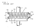
- Japanese Patent Application Laid-Open No.2003-149062 proposes a torque sensor (torque detecting apparatus) having a configuration according to a vertical cross-sectional view shown in FIG. 1 , which is different from the conventional ones.
- This torque sensor comprises an input shaft 1 and an output shaft 2 coaxially connected to each other via a torsion bar (not shown), a ring-shaped 24-pole permanent magnet 15 fixed to the input shaft 1, two magnetic yokes 4c, 4d respectively constituted of a soft magnetic material, fixed to the output shaft 2 so as to be disposed within a magnetic field of the permanent magnet 15 thus to form a magnetic circuit, two flux condensing rings 8c, 8d magnetically connected to the magnetic yokes 4c, 4d respectively to induce the magnetic flux from the magnetic yokes 4c, 4d, flux condensing portions 19c, 19d respectively provided on the flux condensing rings 8c, 8d so as to condense a magnetic flux induced by the
- the magnetic yokes 4c, 4d have to be disposed so as to receive a certain amount of magnetic flux from the permanent magnet 15. In other words, a certain area has to be ensured to allow the magnetic yokes 4c, 4d and the permanent magnet 15 to oppose each other. This, however, inevitably requires that the permanent magnet 15 has a certain length (height) in an axial direction of the input shaft 1, which inhibits reducing an overall dimension of the torque detecting apparatus in the axial direction of the input shaft 1, thus preventing making the torque detecting apparatus more compact.
- the present invention has been conceived in view of the foregoing situation, with an object to provide a torque detecting apparatus having a reduced length in an axial direction of an input shaft, thus to be made smaller in dimensions.
- the present invention provides a torque detecting apparatus as recited in claim 1.
- FIG. 2 is an exploded perspective view showing a configuration of a torque detecting apparatus according to the present invention.
- FIG. 3 is a partial vertical cross-sectional view showing the assembled state of the torque detecting apparatus according to the present invention.
- the torque detecting apparatus according to the present invention is to be mounted on an input shaft 1 as a first shaft and an output shaft 2 as a second shaft, coaxially connected to each other via a torsion bar 3 of a smaller diameter, as a connecting rod.
- the input shaft 1 is coaxially connected to an end portion of the torsion bar 3 with a pin 91
- the output shaft 2 is coaxially connected to the other end portion of the torsion bar 3 with a pin 92. Accordingly, the input shaft 1 and the output shaft 2 are coaxially connected via the torsion bar 3.
- a permanent magnet 5 of a truncated conical shape is coaxially fixed, with the larger diameter portion facing the output shaft 2 side and the smaller diameter portion facing the input shaft 1 side.
- twelve each of N poles and S poles, totally 24 poles, for example, are magnetized at regular intervals along a circumferential direction.
- the output shaft 2 is provided with a smaller and a larger magnetic yokes 4a, 4b, which are soft magnetic materials, coaxially fixed on the end portion on the side of the input shaft 1.
- the magnetic yokes 4a, 4b are disposed so as to cover the outer bevel circumference surface of the truncated conical-shaped permanent magnet 5, with an appropriate distance therebetween.
- the smaller magnetic yoke 4a is provided so as to cover the permanent magnet 5 from the smaller diameter side toward the larger diameter side
- the larger magnetic yoke 4b is provided so as to cover the permanent magnet 5 from the larger diameter side toward the smaller diameter side.
- the magnetic yokes 4a, 4b both have a same shape as the bevel circumference surface of the truncated cone.
- To the smaller magnetic yoke 4a on a plate member formed in the shape of the bevel circumference surface of the truncated cone, provided are twelve teeth 10a projecting in an isosceles triangular shape toward the larger diameter side of the permanent magnet 5, formed at regular intervals along the bevel circumference surface of the truncated cone.
- the larger magnetic yoke 4b on a plate member formed in the shape of the bevel circumference surface of the truncated cone, provided are twelve teeth 10b projecting in an isosceles triangular shape toward the smaller diameter side of the permanent magnet 5, formed at regular intervals along the bevel circumference surface of the truncated cone. Therefore, the respective teeth 10a, 10b of the magnetic yokes 4a, 4b are formed in symmetrical with respect to a straight line along an axial direction of the input shaft 1.
- the respective teeth 10a, 10b of the magnetic yokes 4a, 4b do not necessarily have to be of an isosceles triangular shape mentioned above, but may instead be of an isosceles trapezoidal shape, a rectangular shape (including a square), a semicircular shape, a semi elliptical shape and so forth.
- the respective teeth 10a of the magnetic yoke 4a and the respective teeth 10b of the magnetic yoke 4b are opposite to each other having an offset of appropriate circumferential interval, more specifically an interval of "360/2n" degrees where "n" is the number of the respective teeth 10a, 10b of the magnetic yokes 4a, 4b, so that the projecting tip of the respective teeth 10a of the magnetic yoke 4a is disposed between two adjacent teeth 10b of the magnetic yoke 4b, and likewise the projecting tip of the respective teeth 10b of the magnetic yoke 4b is disposed between two adjacent teeth 10a of the magnetic yoke 4a.
- the teeth 10a, 10b of the magnetic yokes 4a, 4b are, as stated above, formed so as to cover the outer bevel circumference surface of the truncated conical-shaped permanent magnet 5 with an appropriate distance.
- the appropriate distance means a distance where the magnetic yokes 4a, 4b can be positioned within the magnetic field generated by the permanent magnet 5.
- the magnetic yokes 4a, 4b are fixed to the output shaft 2 such that each projecting tip of the respective teeth 10a, 10b of the magnetic yokes 4a, 4b coincides with each boundary between each adjacent N pole and S pole (or each adjacent S pole and N pole) on the permanent magnet 5, under a neutral state where a torque is not applied to the input shaft 1 or the output shaft 2.
- a smaller and a larger flux condensing rings 8a, 8b are disposed parallel to and equally spaced from the magnetic yokes 4a and 4b, respectively.
- the smaller flux condensing ring 8a is magnetically connected to the smaller magnetic yoke 4a, so as to induce a magnetic flux from the magnetic yoke 4a.
- the larger flux condensing ring 8b is magnetically connected to the larger magnetic yoke 4b, so as to induce a magnetic flux from the magnetic yoke 4b.
- a plate-shaped flux condensing portion 19a, 19b located closer to each other than other portions are formed. In a gap formed by the flux condensing portions 19a, 19b, the magnetic flux induced by the flux condensing rings 8a, 8b are condensed.
- two Hall ICs 6 are circumferentially inserted parallel to each other.
- the flux condensing rings 8a, 8b are fixed in a housing (not shown) under the state where the flux condensing rings 8a, 8b are magnetically insulated.
- the two Hall ICs 6 are fixed in the housing which is not shown.
- the respective lead wires 7 of the Hall ICs 6 are soldered to a substrate which is not shown. These lead wires 7 serve to supply the power that activates the Hall ICs 6, and to output a detecting result obtained by the Hall ICs 6.
- a reason that two Hall ICs 6 are provided is to enable the torque detecting apparatus to cancel a temperature drift and increase the sensitivity, by detecting the magnetic flux in opposite directions, for example. Accordingly, it is not necessary to provide two Hall ICs 6, but just one may be provided.
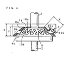
- Such configuration allows reducing a length (height) Y of the torque detecting apparatus according to the present invention in an axial direction of the input shaft 1, compared with the length (height) X of the conventional torque detecting apparatus, which uses the cylindrical permanent magnet 15.
- the volume can be reduced by a portion corresponding to a cross-section indicated by the alternate long and two short dashes line in FIG. 4 , and the length (height) in an axial direction of the input shaft 1 can be reduced by an amount of "X ⁇ Y".
- the magnetic fluxes generated on the magnetic yokes 4a, 4b are respectively induced by the flux condensing rings 8a, 8b, and concentrated on the flux condensing portions 19a, 19b of the flux condensing rings 8a, 8b. Since two Hall ICs 6, 6 are inserted between the flux condensing portions 19a, 19b, the magnetic fluxes respectively induced by the flux condensing rings 8a, 8b are detected by the two Hall ICs 6, 6.
- the Hall ICs 6, 6 can detect an average of the density of the magnetic fluxes generated along the entire circumference of the magnetic yokes 4a, 4b.
- the average of the density of the magnetic fluxes detected by the Hall ICs 6, 6 is proportional to the magnitude of the torque applied to the input shaft 1 or the output shaft 2.
Landscapes
- Physics & Mathematics (AREA)
- Electromagnetism (AREA)
- General Physics & Mathematics (AREA)
- Power Steering Mechanism (AREA)
- Force Measurement Appropriate To Specific Purposes (AREA)
Applications Claiming Priority (1)
| Application Number | Priority Date | Filing Date | Title |
|---|---|---|---|
| JP2004248849A JP4906253B2 (ja) | 2004-08-27 | 2004-08-27 | トルク検出装置 |
Publications (3)
| Publication Number | Publication Date |
|---|---|
| EP1630534A2 EP1630534A2 (en) | 2006-03-01 |
| EP1630534A3 EP1630534A3 (en) | 2007-04-25 |
| EP1630534B1 true EP1630534B1 (en) | 2010-08-18 |
Family
ID=35429472
Family Applications (1)
| Application Number | Title | Priority Date | Filing Date |
|---|---|---|---|
| EP05107865A Expired - Fee Related EP1630534B1 (en) | 2004-08-27 | 2005-08-26 | Torque detecting apparatus |
Country Status (4)
| Country | Link |
|---|---|
| US (1) | US7387034B2 (ja) |
| EP (1) | EP1630534B1 (ja) |
| JP (1) | JP4906253B2 (ja) |
| DE (1) | DE602005022961D1 (ja) |
Families Citing this family (13)
| Publication number | Priority date | Publication date | Assignee | Title |
|---|---|---|---|---|
| JP2007240496A (ja) * | 2006-03-13 | 2007-09-20 | Kayaba Ind Co Ltd | トルクセンサ |
| EP2072985A1 (en) * | 2006-10-12 | 2009-06-24 | NSK Limited | Torque detector, method of producing the torque detector, and electric power steering device |
| EP2088397A4 (en) * | 2006-10-26 | 2011-06-08 | Furukawa Electric Co Ltd | ROTATION ANGLE DETECTOR |
| WO2008105541A1 (ja) * | 2007-03-01 | 2008-09-04 | Nsk Ltd. | トルク検出器及び電動パワーステアリング装置、クローポールの製造方法及びトルク検出器の製造方法 |
| DE202008001763U1 (de) * | 2008-02-08 | 2009-06-10 | Brose Fahrzeugteile Gmbh & Co. Kommanditgesellschaft, Hallstadt | Antriebseinheit für einen elektrischen Fensterheber |
| US20100180696A1 (en) * | 2009-01-16 | 2010-07-22 | Delphi Technologies Inc. | Systems involving compact torque sensing |
| KR101238594B1 (ko) | 2010-07-27 | 2013-02-28 | 엘지이노텍 주식회사 | 스티어링 시스템의 토크 센서 |
| US8468898B2 (en) * | 2010-10-28 | 2013-06-25 | General Electric Company | Method and apparatus for continuous sectional magnetic encoding to measure torque on large shafts |
| JP6171694B2 (ja) * | 2013-08-02 | 2017-08-02 | 株式会社ジェイテクト | トルク検出装置および電動パワーステアリング装置 |
| US11874140B2 (en) * | 2016-02-17 | 2024-01-16 | Infineon Technologies Ag | Tapered magnet |
| US20170234699A1 (en) * | 2016-02-17 | 2017-08-17 | Infineontechnologies Ag | Tapered magnet |
| JP6670230B2 (ja) * | 2016-12-22 | 2020-03-18 | 株式会社Soken | トルク検出装置 |
| JP6691500B2 (ja) * | 2017-03-31 | 2020-04-28 | 株式会社Soken | トルク検出装置 |
Family Cites Families (8)
| Publication number | Priority date | Publication date | Assignee | Title |
|---|---|---|---|---|
| JPH02162211A (ja) * | 1988-12-16 | 1990-06-21 | Copal Co Ltd | 相対変位検出装置 |
| JPH07245926A (ja) * | 1994-03-08 | 1995-09-19 | Mitsubishi Electric Corp | ブラシレスモータ |
| JP4126159B2 (ja) * | 2001-01-11 | 2008-07-30 | 矢崎総業株式会社 | 回転検出装置用マグネット及び回転検出装置用マグネットの製造方法 |
| JP3874642B2 (ja) * | 2001-05-18 | 2007-01-31 | 株式会社デンソー | トルクセンサ及びこのトルクセンサを具備する電動パワーステアリング装置 |
| DE10222118B4 (de) * | 2001-05-18 | 2006-10-05 | Denso Corp., Kariya | Drehmomentsensor und elektrisches Servolenkungssystem mit Drehmomentsensor |
| JP2004020527A (ja) * | 2002-06-20 | 2004-01-22 | Nippon Soken Inc | トルクセンサ |
| DE10261574A1 (de) * | 2002-12-23 | 2004-07-01 | Robert Bosch Gmbh | Klauenpolmotor |
| US20050264118A1 (en) * | 2004-03-01 | 2005-12-01 | Kascak Peter E | Conical bearingless motor/generator |
-
2004
- 2004-08-27 JP JP2004248849A patent/JP4906253B2/ja not_active Expired - Fee Related
-
2005
- 2005-08-25 US US11/213,032 patent/US7387034B2/en not_active Expired - Fee Related
- 2005-08-26 DE DE602005022961T patent/DE602005022961D1/de active Active
- 2005-08-26 EP EP05107865A patent/EP1630534B1/en not_active Expired - Fee Related
Also Published As
| Publication number | Publication date |
|---|---|
| JP4906253B2 (ja) | 2012-03-28 |
| US7387034B2 (en) | 2008-06-17 |
| EP1630534A2 (en) | 2006-03-01 |
| EP1630534A3 (en) | 2007-04-25 |
| JP2006064577A (ja) | 2006-03-09 |
| DE602005022961D1 (de) | 2010-09-30 |
| US20060042405A1 (en) | 2006-03-02 |
Similar Documents
| Publication | Publication Date | Title |
|---|---|---|
| EP1630534B1 (en) | Torque detecting apparatus | |
| JP6311926B2 (ja) | トルクセンサおよび電動パワーステアリング装置 | |
| US6928888B2 (en) | Torque sensor for detecting a shaft torque | |
| US9366590B2 (en) | Torque sensor for measuring torsion of steering column and measurement method using the same | |
| JP6160214B2 (ja) | トルク検出装置および同装置を備える電動パワーステアリング装置 | |
| JP2006038767A (ja) | トルク検出装置 | |
| KR102454974B1 (ko) | 토크 센서 장치, 토크 결정 방법, 스테이터 및 스테이터 구성체 | |
| JP4822681B2 (ja) | トルク検出装置 | |
| JP5071407B2 (ja) | トルクセンサ及びこれを用いる電動パワーステアリング装置 | |
| JP5412194B2 (ja) | 相対角度検出装置及びパワーステアリング装置 | |
| JP2008216019A (ja) | トルクセンサ及び電動式パワーステアリング装置 | |
| US9945743B2 (en) | Torque sensor device | |
| JP5469937B2 (ja) | 相対角度検出装置及びパワーステアリング装置 | |
| JP4073384B2 (ja) | トルク検出装置 | |
| JP2009020064A (ja) | トルク検出器及び電動パワーステアリング装置 | |
| JP4036806B2 (ja) | トルク検出装置 | |
| JP2005265581A (ja) | トルク検出装置 | |
| JP2012237727A (ja) | トルクセンサ | |
| JP2005069994A (ja) | トルク検出装置 | |
| JP4030944B2 (ja) | トルク検出装置 | |
| JP4030945B2 (ja) | トルク検出装置 | |
| JP2005265593A (ja) | トルク検出装置 | |
| KR20160029991A (ko) | 토크 센서 장치 | |
| JP2009085841A (ja) | トルク検出器及び電動パワーステアリング装置 | |
| KR20160029990A (ko) | 토크 센서 장치 |
Legal Events
| Date | Code | Title | Description |
|---|---|---|---|
| PUAI | Public reference made under article 153(3) epc to a published international application that has entered the european phase |
Free format text: ORIGINAL CODE: 0009012 |
|
| AK | Designated contracting states |
Kind code of ref document: A2 Designated state(s): AT BE BG CH CY CZ DE DK EE ES FI FR GB GR HU IE IS IT LI LT LU LV MC NL PL PT RO SE SI SK TR |
|
| AX | Request for extension of the european patent |
Extension state: AL BA HR MK YU |
|
| RAP1 | Party data changed (applicant data changed or rights of an application transferred) |
Owner name: DENSO CORPORATION Owner name: JTEKT CORPORATION Owner name: FAVESS CO., LTD. |
|
| RAP1 | Party data changed (applicant data changed or rights of an application transferred) |
Owner name: DENSO CORPORATION Owner name: JTEKT CORPORATION |
|
| PUAL | Search report despatched |
Free format text: ORIGINAL CODE: 0009013 |
|
| AK | Designated contracting states |
Kind code of ref document: A3 Designated state(s): AT BE BG CH CY CZ DE DK EE ES FI FR GB GR HU IE IS IT LI LT LU LV MC NL PL PT RO SE SI SK TR |
|
| AX | Request for extension of the european patent |
Extension state: AL BA HR MK YU |
|
| 17P | Request for examination filed |
Effective date: 20071022 |
|
| AKX | Designation fees paid |
Designated state(s): DE FR GB |
|
| 17Q | First examination report despatched |
Effective date: 20090304 |
|
| GRAP | Despatch of communication of intention to grant a patent |
Free format text: ORIGINAL CODE: EPIDOSNIGR1 |
|
| GRAS | Grant fee paid |
Free format text: ORIGINAL CODE: EPIDOSNIGR3 |
|
| GRAA | (expected) grant |
Free format text: ORIGINAL CODE: 0009210 |
|
| AK | Designated contracting states |
Kind code of ref document: B1 Designated state(s): DE FR GB |
|
| REG | Reference to a national code |
Ref country code: GB Ref legal event code: FG4D |
|
| REF | Corresponds to: |
Ref document number: 602005022961 Country of ref document: DE Date of ref document: 20100930 Kind code of ref document: P |
|
| PLBE | No opposition filed within time limit |
Free format text: ORIGINAL CODE: 0009261 |
|
| STAA | Information on the status of an ep patent application or granted ep patent |
Free format text: STATUS: NO OPPOSITION FILED WITHIN TIME LIMIT |
|
| 26N | No opposition filed |
Effective date: 20110519 |
|
| REG | Reference to a national code |
Ref country code: DE Ref legal event code: R097 Ref document number: 602005022961 Country of ref document: DE Effective date: 20110519 |
|
| PGFP | Annual fee paid to national office [announced via postgrant information from national office to epo] |
Ref country code: DE Payment date: 20140821 Year of fee payment: 10 |
|
| PGFP | Annual fee paid to national office [announced via postgrant information from national office to epo] |
Ref country code: GB Payment date: 20140820 Year of fee payment: 10 Ref country code: FR Payment date: 20140808 Year of fee payment: 10 |
|
| REG | Reference to a national code |
Ref country code: DE Ref legal event code: R119 Ref document number: 602005022961 Country of ref document: DE |
|
| GBPC | Gb: european patent ceased through non-payment of renewal fee |
Effective date: 20150826 |
|
| REG | Reference to a national code |
Ref country code: FR Ref legal event code: ST Effective date: 20160429 |
|
| PG25 | Lapsed in a contracting state [announced via postgrant information from national office to epo] |
Ref country code: GB Free format text: LAPSE BECAUSE OF NON-PAYMENT OF DUE FEES Effective date: 20150826 Ref country code: DE Free format text: LAPSE BECAUSE OF NON-PAYMENT OF DUE FEES Effective date: 20160301 |
|
| PG25 | Lapsed in a contracting state [announced via postgrant information from national office to epo] |
Ref country code: FR Free format text: LAPSE BECAUSE OF NON-PAYMENT OF DUE FEES Effective date: 20150831 |