EP1630319A2 - Freitragende Halterung für eine Seitenblende - Google Patents
Freitragende Halterung für eine Seitenblende Download PDFInfo
- Publication number
- EP1630319A2 EP1630319A2 EP05017928A EP05017928A EP1630319A2 EP 1630319 A2 EP1630319 A2 EP 1630319A2 EP 05017928 A EP05017928 A EP 05017928A EP 05017928 A EP05017928 A EP 05017928A EP 1630319 A2 EP1630319 A2 EP 1630319A2
- Authority
- EP
- European Patent Office
- Prior art keywords
- side panel
- headband
- holder
- inner edge
- inner edges
- Prior art date
- Legal status (The legal status is an assumption and is not a legal conclusion. Google has not performed a legal analysis and makes no representation as to the accuracy of the status listed.)
- Granted
Links
- 230000001681 protective effect Effects 0.000 claims description 14
- 238000010409 ironing Methods 0.000 claims description 6
- 238000004873 anchoring Methods 0.000 claims description 4
- 230000003750 conditioning effect Effects 0.000 claims description 3
- 239000011521 glass Substances 0.000 claims description 3
- 229910052751 metal Inorganic materials 0.000 claims description 3
- 239000002184 metal Substances 0.000 claims description 3
- 229920003229 poly(methyl methacrylate) Polymers 0.000 claims description 3
- 239000004926 polymethyl methacrylate Substances 0.000 claims description 3
- 239000000463 material Substances 0.000 claims description 2
- 230000001154 acute effect Effects 0.000 abstract 1
- 238000010276 construction Methods 0.000 description 2
- 238000009434 installation Methods 0.000 description 2
- 239000003562 lightweight material Substances 0.000 description 2
- 229910052782 aluminium Inorganic materials 0.000 description 1
- XAGFODPZIPBFFR-UHFFFAOYSA-N aluminium Chemical compound [Al] XAGFODPZIPBFFR-UHFFFAOYSA-N 0.000 description 1
- 210000003414 extremity Anatomy 0.000 description 1
- 210000001364 upper extremity Anatomy 0.000 description 1
Images


Classifications
-
- E—FIXED CONSTRUCTIONS
- E04—BUILDING
- E04F—FINISHING WORK ON BUILDINGS, e.g. STAIRS, FLOORS
- E04F10/00—Sunshades, e.g. Florentine blinds or jalousies; Outside screens; Awnings or baldachins
- E04F10/005—Rigidly-arranged sunshade roofs with coherent surfaces
-
- E—FIXED CONSTRUCTIONS
- E04—BUILDING
- E04B—GENERAL BUILDING CONSTRUCTIONS; WALLS, e.g. PARTITIONS; ROOFS; FLOORS; CEILINGS; INSULATION OR OTHER PROTECTION OF BUILDINGS
- E04B2/00—Walls, e.g. partitions, for buildings; Wall construction with regard to insulation; Connections specially adapted to walls
- E04B2/74—Removable non-load-bearing partitions; Partitions with a free upper edge
- E04B2/82—Removable non-load-bearing partitions; Partitions with a free upper edge characterised by the manner in which edges are connected to the building; Means therefor; Special details of easily-removable partitions as far as related to the connection with other parts of the building
Definitions
- the invention relates to a cantilever bracket for a side panel, consisting of an elongated panel plate with holding devices for anchoring the side panel next to an outside wall door.
- Such side panels are usually mounted on both sides of canopies to protect the entrance from wind and rain.
- the object of the invention is to provide a cantilevered bracket, which can be inexpensively manufactured in a stable and sustainable construction in lightweight construction and also is easy to assemble.
- the items required for this purpose should be available prepared for example in the hardware store as a kit, so that the attachment of such a side panel mount on the outside wall for a hobbyist is easy to accomplish.
- a cantilevered bracket of the above type in which the holding device of two flat, acute-angled converging and the plate with their inner edges on both sides clamped holding brackets is formed, which are integrally connected to each other at their narrow ends by a flexible web and Have at their wider ends means for connecting these ends after clamping the plates and 90 ° angled legs for conditioning and screwing the headband on the outer wall.
- the headband are hereby preferably designed so that their inner edges have at their wider end a pointing to the opposite inner edge molded projection, which can be pressed into a recess corresponding to the projection on the opposite inner edge of the side and locked in the ironing plane.
- This bracket offers the great advantage that the attachment of the headband on the orifice plate does not require any screwing and is prepared after pinching the diaphragm plate simply by mere engagement of the connecting means for anchoring to the facade wall.
- the side panel will consist in the present case of a translucent plate made of glass, preferably acrylic glass or similar lightweight material, which is bordered at its longitudinal edges with a U-shaped protective profile made of light metal.
- the legs of the protective profiles advantageously at the points provided for clamping the headband locations corresponding to the temple thickness wide slots in which the inner edges of the headband when pressing on the plate dive. As a result, the headband can be easily positioned in height and connect to the side panel.
- the inner edges of the headband should be covered between the protective profiles of a cross-sectionally U-shaped rubber profile and cut at a depth corresponding to the thickness of the rubber profile.
- the holding device shown in the figures is used to attach a side panel to the facade wall next to the front door. It consists essentially of two flat and acute-angled converging headband 1 and 2, with which the diaphragm plate 3 can be clamped on both sides. These brackets 1 and 2 are integrally connected to each other at their narrow ends 4 by a flexible web 6 and have at their wider ends 5 means for connecting the ends after clamping the plates 3 and 90 ° angled leg 7 for conditioning and screwing the headband 1,2 on the façade wall.
- the headband 1.2 consist of corrosion-free material.
- a translucent glass plate As a side panel is usually a translucent glass plate is used, which preferably consists of acrylic glass or similar lightweight material and at its longitudinal edges 13 with a U-shaped protective profile 14 made of light metal, bsp. Aluminum profile is edged.
- the legs 15 of these protective profiles 14 have slots 16 in a width at the points provided for clamping the retaining clips 1 and 2, which correspond to the thickness of the retaining clips 1, 2, so that the inner edges 8 and 11 of the retaining clips 1 and 2 dive into these slots 16 when pressed against the panel plate 3.
- the inner edges 8 and 11 are cut along the length between the protective profiles 14 according to the thickness of the rubber profile 17.
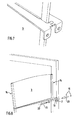
- the inner edge 8 of the retaining clip 1, which is provided with the latching projection 9, is cut in the width of the limb 15 corresponding to its wall thickness at the location of the protective profile 14, for assembly reasons. This is necessary because when positioning the headband 1 and 2 first, as shown in Figure 6, the one ironing edge 11 when pressing against the protective profile 14 in the slot 16 on the rear leg 15 is immersed, while the other ironing edge 8 below the ironing plane on the front leg 15 so long applied until the projection 9 is pressed up according to the mounting pattern in Figure 7 in the recess 12 and locked there.
- Figure 8 shows a section of the side panel with the upper bracket 1 and 2 before anchoring to the facade wall.
- the angled legs 7 of the bracket 1 and 2 are provided for this purpose with a screw hole 19. After dowel holes drilled at the distance of the screw holes 19 on the facade wall and the dowels 20 are inserted, the screws 21 are inserted through the screw holes 19 and screwed to the stop of the screw heads 22 to the hanger arms 7 in the dowel 20.
Landscapes
- Engineering & Computer Science (AREA)
- Architecture (AREA)
- Civil Engineering (AREA)
- Structural Engineering (AREA)
- Physics & Mathematics (AREA)
- Electromagnetism (AREA)
- Securing Of Glass Panes Or The Like (AREA)
Abstract
Description
- Die Erfindung bezieht sich auf eine freitragende Halterung für eine Seitenblende, bestehend aus einer länglichen Blendenplatte mit Haltevorrichtungen zur Verankerung der Seitenblende neben einer Außenwandtüre. Derartige Seitenblenden werden üblicher weise beiderseits von Vordächern angebracht, um den Eingangsbereich vor Wind und Regen zu schützen.
- Aufgabe der Erfindung ist es, eine freitragende Halterung zu schaffen, welche in einer stabilen und tragfähigen Konstruktion in Leichtbauweise kostengünstig hergestellt werden kann und darüber hinaus auch leicht zusammenzubauen ist. Die hierzu notwendigen Einzelteile sollten beispielsweise auf dem Baumarkt als Baukasten vorgerichtet erhältlich sein, so dass die Anbringung einer solchen Seitenblendenhalterung an der Außenwand für einen Hobbywerker leicht zu bewerkstelligen ist.
- Zur Lösung dieser Aufgabe wird eine freitragende Halterung der oben genannten Art vorgeschlagen, bei der die Haltevorrichtung aus zwei flachen, spitzwinklig zusammenlaufenden und die Platte mit ihren Innenkanten beiderseits einklemmenden Haltebügeln gebildet ist, welche an ihren schmalen Enden durch einen biegsamen Steg einteilig miteinander verbunden sind und an ihren breiteren Enden Mittel zum Verbinden dieser Enden nach dem Einklemmen der Platten sowie um 90° abgewinkelte Schenkel zur Anlage und Verschraubung der Haltebügel an der Außenwand aufweisen.
- Die Haltebügel sind hierbei vorzugsweise so ausgebildet, dass deren Innenkanten am ihrem breiteren Ende einen zur gegenüberliegenden Innenkante weisenden angeformten Vorsprung aufweisen, welcher in eine dem Vorsprung entsprechende Aussparung an der gegenüberliegenden Innenkante von der Seite her eingedrückt und in der Bügelebene eingerastet werden kann.
- Diese Halterung bietet den großen Vorteil, dass die Befestigung der Haltebügel auf der Blendenplatte ohne jede Verschraubung auskommt und nach dem Einklemmen der Blendenplatte einfach durch bloßes Einrasten der Verbindungsmittel zur Verankerung an der Fassadenwand vorbereitet ist.
- Die Seitenblende wird im vorliegenden Fall aus einer lichtdurchlässigen Platte aus Glas, vorzugsweise Acrylglas oder ähnlich leichtem Material bestehen, welche an ihren Längskanten mit einem u-förmigem Schutzprofil aus Leichtmetall eingefasst ist. In diesem Fall weisen die Schenkel der Schutzprofile vorteilhafter weise an den zum Anklemmen der Haltebügel vorgesehen Stellen entsprechend der Bügelstärke breite Schlitze auf, in welche die Innenkanten die Haltebügel beim Andrücken an die Platte eintauchen. Dadurch lassen sich die Haltebügel in ihren Höhe leicht positionieren und mit der Seitenblende verbinden.
- Zur sanften und vibrationsfreien Anlage der Haltebügel an der Blendenplatte sollten die Innenkanten der Haltebügel zwischen den Schutzprofilen von einem im Querschnitt u-förmigen Gummiprofil abgedeckt und in einer Tiefe entsprechend der Dicke des Gummiprofilsteges eingeschnitten sein.
- In der Zeichnung ist eine bevorzugte Ausführungsform der Erfindung dargestellt, welche in der nachfolgenden Beschreibung näher erläutert wird. Es zeigen:
- Figur 1
- Eine neben einer Außenwandtüre nach der Erfindung gehaltene Seitenblende in perspektivischer Darstellung,
- Figur 2
- Ein erfindungsgemäß ausgebildeter Haltebügel in perspektivischer Darstellung und in geöffneter Stellung,
- Figur 3
- Der gleiche Haltebügel beim Aufschieben in Richtung des Pfeils über die Seitenblende,
- Figur 4
- Einen Ausschnitt des eingeschobenen Haltebügels bei der Positionierung der schmalen Bügel Enden über den Schlitzen des Schutzprofils,
- Figur 5
- Einen Ausschnitt der breiteren Bügel Enden in der gleichen Montageposition beim Andrücken einer Bügelkante in Richtung des Pfeils,
- Figur 6
- Der gleiche Montageausschnitt nach dem Andrücken des gegenüberliegenden Bügels in Richtung des Pfeils A an das Schutzprofil bis zum deckungsgleichen Überlappen der Verbindungsmittel vor dem Hochdrücken des Bügels in Richtung des Pfeils H,
- Figur 7
- Der gleiche Montageausschnitt nach dem Einrasten des Verbindungsvorsprungs in die Aussparung und
- Figur 8
- Die Montage der in den Haltebügeln eingeklemmten Seitenblende an der Hauswand.
- Die in den Figuren dargestellte Haltevorrichtung dient zur Befestigung einer Seitenblende an der Fassadenwand neben der Haustüre. Sie besteht im wesentlichen aus zwei flachen und spitzwinklig zusammenlaufenden Haltebügeln 1 und 2, mit welchen die Blendenplatte 3 beiderseits eingeklemmt werden kann. Diese Haltebügel 1 und 2 sind an ihren schmalen Enden 4 durch einen biegsamen Steg 6 einteilig miteinander verbunden und weisen an ihren breiteren Enden 5 Mittel zum Verbinden der Enden nach dem Einklemmen der Platten 3 sowie um 90° abgewinkelte Schenkel 7 zur Anlage und Verschraubung der Haltebügel 1,2 an der Fassadenwand auf. Die Haltebügel 1,2 bestehen aus korrosionsfreiem Material.
- Wie aus Figur 2 ersichtlich, weist eine der Innenkanten 8 am breiteren Ende 5 einen etwa kreisförmigen Vorsprung 9 auf, welcher an der Innenkante 8 über einen schmalen Verbindungssteg 10 einteilig angeformt ist, während an der gegenüberliegenden Innenkante 11 eine kreisringförmige Aussparung 12 eingeschnitten ist, in welche der Vorsprung 9 von der Seite her, d.h. von oben oder unten eingedrückt und in der Bügelebene verrastet werden kann.
- Als Seitenblende wird üblicher weise eine lichtdurchlässige Glasplatte verwendet, welche vorzugsweise aus Acrylglas oder ähnlich leichtem Material besteht und an ihren Längskanten 13 mit einem u-förmigen Schutzprofil 14 aus Leichtmetall, bsp. Aluminiumprofil eingefasst ist. Wie aus Figur 3 erkennbar, weisen die Schenkel 15 dieser Schutzprofile 14 an den zum Anklemmen der Haltebügel 1 und 2 vorgesehenen Stellen Schlitze 16 in einer Breite auf, welche der Stärke der Haltebügel 1, 2 entsprechen, so dass die Innenkanten 8 und 11 der Haltebügel 1 und 2 beim Andrücken an die Blendenplatte 3 in diese Schlitze 16 eintauchen.
- Die Innenkanten 8 und 11 der Haltebügel 1 und 2 werden, wie aus Figur 2 ersichtlich, zwischen den Schutzprofilen 14 zweckmäßiger weise von einem im Querschnitt u-förmig ausgebildeten Gummiprofil 17 abgedeckt, damit die Haltebügel 1 und 2 an der Blendenplatte 3 vibrationsfrei anliegen. Hierzu sind die Innenkanten 8 und 11 auf der Länge zwischen den Schutzprofilen 14 entsprechend der Stärke des Gummiprofils 17 eingeschnitten.
- Außerdem ist noch - aus Montagegründen - die mit dem Einrastvorsprung 9 versehene Innenkante 8 des Haltebügels 1 an der Stelle des Schutzprofils 14 auf der Breite des Schenkels 15 entsprechend dessen Wandstärke eingeschnitten. Dies ist deshalb erforderlich, weil beim Positionieren der Haltebügel 1 und 2 zunächst, wie aus Figur 6 ersichtlich, die eine Bügelkante 11 beim Andrücken an das Schutzprofil 14 in den Schlitz 16 auf dessen hinteren Schenkel 15 eintaucht, während die andere Bügelkante 8 unterhalb der Bügelebene am vorderen Schenkel 15 so lange anliegt, bis der Vorsprung 9 entsprechend dem Montagebild in Figur 7 in die Aussparung 12 hoch gedrückt und dort eingerastet ist.
- Figur 8 zeigt einen Ausschnitt der Seitenblende mit dem oberen Haltebügel 1 und 2 vor der Verankerung an der Fassadenwand. Die abgewinkelten Schenkel 7 der Bügel 1 und 2 sind zu diesem Zwecke mit einem Schraubenloch 19 versehen. Nachdem im Abstand der Schraubenlöcher 19 an der Fassadenwand Dübellöcher gebohrt und die Dübel 20 eingesetzt sind, werden die Schrauben 21 durch die Schraubenlöcher 19 eingeführt und bis zum Anschlag der Schraubenköpfe 22 an die Bügelschenkel 7 in die Dübel 20 eingedreht.
-
- 1
- Haltebügel
- 2
- Haltebügel
- 3
- Blendenplatte
- 4
- Schmaleres Ende
- 5
- Breiteres Ende
- 6
- Biegsamer Steg
- 7
- Befestigungsschenkel
- 8
- Innenkante
- 9
- Vorsprung
- 10
- Verbindungssteg
- 11
- Innenkante
- 12
- Aussparung
- 13
- Längskanten
- 14
- Schutzprofil
- 15
- Schenkel
- 16
- Schlitze
- 17
- Gummiprofil
- 18
- Schraubenloch
- 19
- Dübelloch
- 20
- Dübel
- 21
- Schraube
- 22
- Schraubenkopf
Claims (5)
- Freitragende Halterung für eine Seitenblende, bestehend aus einer länglichen Blendenplatte (3) mit Haltevorrichtungen zur Verankerung der Seitenblende neben einer Außenwandtüre, dadurch gekennzeichnet,• dass die Haltevorrichtung aus zwei flachen, spitzwinklig zusammenlaufenden und die Platte (3) mit ihren Innenkanten (8,11) beiderseits einklemmenden Haltebügeln (1,2) gebildet ist, welche• an ihren schmaleren Enden (4) durch einen biegsamen Steg (6) einteilig miteinander verbunden sind und• an ihren breiteren Enden (5) Mittel zum Verbinden dieser Enden nach dem Einklemmen der Platten (3) sowie um 90° abgewinkelte Befestigungsschenkel (7) zur Anlage und Verschraubung der Haltebügel (1,2) an der Außenwand aufweisen.
- Halterung für eine Seitenblende nach Anspruch 1, dadurch gekennzeichnet, dass die Innenkante (8) am breiteren Ende (5) einen zur gegenüberliegenden Innenkante (11) weisenden angeformten Vorsprung (9) aufweist, welcher in eine dem Vorsprung (9) entsprechende Aussparung (12) an der gegenüberliegenden Innenkante (11) von der Seite her eingedrückt und in der Bügelebene eingerastet werden kann.
- Halterung für eine Seitenblende nach Anspruch 1 oder 2, wobei die Seitenblende aus einer lichtdurchlässigen Platte (3) aus Glas, vorzugsweise Acrylglas oder ähnlichem Material besteht und an ihren Längskanten (13) mit einem u-förmigem ausgebildeten Schutzprofil (14) aus Leichtmetall eingefasst ist, dadurch gekennzeichnet, dass die Schenkel (15) der Schutzprofile (14) an den zum Anklemmen der Haltebügel (1,2) vorgesehenen Stellen entsprechend der Bügelstärke breite Schlitze (16) aufweisen, in welche die Innenkanten (8,11) der Haltebügel (1,2) beim Andrücken an die Platte (3) eintauchen.
- Halterung für eine Seitenblende nach Anspruch 3, dadurch gekennzeichnet, dass die Innenkanten (8,11) der Haltebügel (1,2) zwischen den Schutzprofilen (14) von einem im Querschnitt u-förmigen Gummiprofil (17) abgedeckt sind, wobei die Innenkanten (8,11) entsprechend der Stärke des Gummiprofils (17) eingeschnitten ist.
- Halterung für eine Seitenblende nach Anspruch 3, dadurch gekennzeichnet, dass die mit dem Einrastvorsprung (9) versehene Innenkante (8) des Haltebügels (1) auf der Breite (B) des Schenkels (15) des Schutzprofils (14) entsprechend seiner Wandstärke eingeschnitten ist.
Applications Claiming Priority (1)
| Application Number | Priority Date | Filing Date | Title |
|---|---|---|---|
| DE200420013440 DE202004013440U1 (de) | 2004-08-27 | 2004-08-27 | Freitragende Halterung für eine Seitenblende |
Publications (3)
| Publication Number | Publication Date |
|---|---|
| EP1630319A2 true EP1630319A2 (de) | 2006-03-01 |
| EP1630319A3 EP1630319A3 (de) | 2008-10-01 |
| EP1630319B1 EP1630319B1 (de) | 2009-07-15 |
Family
ID=34178151
Family Applications (1)
| Application Number | Title | Priority Date | Filing Date |
|---|---|---|---|
| EP20050017928 Expired - Lifetime EP1630319B1 (de) | 2004-08-27 | 2005-08-18 | Freitragende Seitenblende |
Country Status (2)
| Country | Link |
|---|---|
| EP (1) | EP1630319B1 (de) |
| DE (2) | DE202004013440U1 (de) |
Citations (1)
| Publication number | Priority date | Publication date | Assignee | Title |
|---|---|---|---|---|
| US1229745A (en) | 1914-06-24 | 1917-06-12 | Charles H Hahn | Partition structure for toilet-rooms. |
Family Cites Families (2)
| Publication number | Priority date | Publication date | Assignee | Title |
|---|---|---|---|---|
| FR1458709A (fr) * | 1965-10-06 | 1966-03-04 | Sanymetal Products Company | Compartiments suspendus à la paroi verticale d'un local |
| DE2507094A1 (de) * | 1975-02-19 | 1976-09-02 | Kraemer Gmbh | Seitenblende |
-
2004
- 2004-08-27 DE DE200420013440 patent/DE202004013440U1/de not_active Expired - Lifetime
-
2005
- 2005-08-18 EP EP20050017928 patent/EP1630319B1/de not_active Expired - Lifetime
- 2005-08-18 DE DE200550007691 patent/DE502005007691D1/de not_active Expired - Lifetime
Patent Citations (1)
| Publication number | Priority date | Publication date | Assignee | Title |
|---|---|---|---|---|
| US1229745A (en) | 1914-06-24 | 1917-06-12 | Charles H Hahn | Partition structure for toilet-rooms. |
Also Published As
| Publication number | Publication date |
|---|---|
| DE202004013440U1 (de) | 2005-02-03 |
| EP1630319B1 (de) | 2009-07-15 |
| EP1630319A3 (de) | 2008-10-01 |
| DE502005007691D1 (de) | 2009-08-27 |
Similar Documents
| Publication | Publication Date | Title |
|---|---|---|
| DE10338816B3 (de) | Halterung für eine Platte, insbesondere für eine Glasscheibe | |
| EP0180837B2 (de) | Bausatz für eine Haltevorrichtung für Vorhangfassaden | |
| DE2059829A1 (de) | Struktursystem fuer den Zusammenbau von vorgefertigten Konstruktionen | |
| DE202007004760U1 (de) | Freitragendes Vordach | |
| DE4000969C2 (de) | Anordnung zur Befestigung von Gebäudeplatten an Gebäudewänden | |
| EP1544373B1 (de) | Freitragendes Vordach | |
| EP1630319B1 (de) | Freitragende Seitenblende | |
| DE102006019755A1 (de) | Freitragendes Vordach | |
| DE1509557A1 (de) | Anordnung zum klemmenden Verbinden von Glasscheiben od.dgl. mit den Profilrahmen von Fenstern und Tueren | |
| DE102012023859B4 (de) | Leistenanordnung | |
| DE19730203C2 (de) | Überhangstreifen für ein Anschlußblech für Gebäude | |
| DE29720306U1 (de) | Adapterleiste für Tragprofile von abgehängten Decken | |
| EP3098361A1 (de) | Flächenkonstruktion für die ausbildung von wänden, trennwänden, fassaden und dgl | |
| DE4438026C1 (de) | Trennwand für Duschen | |
| DE3826444C2 (de) | ||
| DE2806872A1 (de) | Fassadenunterkonstruktion | |
| DE9406362U1 (de) | Aufschiebebeschlag | |
| CH694209A5 (de) | Profilkonstruktion, insbesondere fuer den Aufbau von Raumteilern. | |
| DE29717928U1 (de) | Befestigungssystem zur Montage von Decken- und Wandverkleidungen | |
| DE29705459U1 (de) | Vorrichtung zur Montage von Glaselementen an einem Tragrahmen zur Herstellung einer Fassadenverglasung | |
| DE10052725C2 (de) | Vorrichtung zur Verankerung von insbesondere U-förmig profilierten Vertikal- und Schrägverglasungen an Bauwerken, insbesondere im Fassadenbau | |
| WO2020127770A1 (de) | Montageclip zur schwimmenden lagerung von wand- und deckenpaneelen | |
| DE3546145A1 (de) | Vorhangfassadenkonstruktion | |
| CH695277A5 (de) | Aufbau einer Glastrennwand. | |
| EP1207245A2 (de) | Befestigungselement für Dämmplatten |
Legal Events
| Date | Code | Title | Description |
|---|---|---|---|
| PUAI | Public reference made under article 153(3) epc to a published international application that has entered the european phase |
Free format text: ORIGINAL CODE: 0009012 |
|
| AK | Designated contracting states |
Kind code of ref document: A2 Designated state(s): AT BE BG CH CY CZ DE DK EE ES FI FR GB GR HU IE IS IT LI LT LU LV MC NL PL PT RO SE SI SK TR |
|
| AX | Request for extension of the european patent |
Extension state: AL BA HR MK YU |
|
| PUAL | Search report despatched |
Free format text: ORIGINAL CODE: 0009013 |
|
| AK | Designated contracting states |
Kind code of ref document: A3 Designated state(s): AT BE BG CH CY CZ DE DK EE ES FI FR GB GR HU IE IS IT LI LT LU LV MC NL PL PT RO SE SI SK TR |
|
| AX | Request for extension of the european patent |
Extension state: AL BA HR MK YU |
|
| 17P | Request for examination filed |
Effective date: 20081211 |
|
| 17Q | First examination report despatched |
Effective date: 20090127 |
|
| GRAP | Despatch of communication of intention to grant a patent |
Free format text: ORIGINAL CODE: EPIDOSNIGR1 |
|
| RTI1 | Title (correction) |
Free format text: CANTILEVERED SIDE SCREEN |
|
| GRAS | Grant fee paid |
Free format text: ORIGINAL CODE: EPIDOSNIGR3 |
|
| AKX | Designation fees paid |
Designated state(s): AT BE BG CH CY CZ DE DK EE ES FI FR GB GR HU IE IS IT LI LT LU LV MC NL PL PT RO SE SI SK TR |
|
| GRAA | (expected) grant |
Free format text: ORIGINAL CODE: 0009210 |
|
| AK | Designated contracting states |
Kind code of ref document: B1 Designated state(s): AT BE BG CH CY CZ DE DK EE ES FI FR GB GR HU IE IS IT LI LT LU LV MC NL PL PT RO SE SI SK TR |
|
| REG | Reference to a national code |
Ref country code: CH Ref legal event code: EP Ref country code: GB Ref legal event code: FG4D Free format text: NOT ENGLISH |
|
| REG | Reference to a national code |
Ref country code: IE Ref legal event code: FG4D |
|
| REF | Corresponds to: |
Ref document number: 502005007691 Country of ref document: DE Date of ref document: 20090827 Kind code of ref document: P |
|
| REG | Reference to a national code |
Ref country code: CH Ref legal event code: NV Representative=s name: BOVARD AG PATENTANWAELTE |
|
| NLV1 | Nl: lapsed or annulled due to failure to fulfill the requirements of art. 29p and 29m of the patents act | ||
| PG25 | Lapsed in a contracting state [announced via postgrant information from national office to epo] |
Ref country code: ES Free format text: LAPSE BECAUSE OF FAILURE TO SUBMIT A TRANSLATION OF THE DESCRIPTION OR TO PAY THE FEE WITHIN THE PRESCRIBED TIME-LIMIT Effective date: 20091026 Ref country code: SE Free format text: LAPSE BECAUSE OF FAILURE TO SUBMIT A TRANSLATION OF THE DESCRIPTION OR TO PAY THE FEE WITHIN THE PRESCRIBED TIME-LIMIT Effective date: 20090715 Ref country code: FI Free format text: LAPSE BECAUSE OF FAILURE TO SUBMIT A TRANSLATION OF THE DESCRIPTION OR TO PAY THE FEE WITHIN THE PRESCRIBED TIME-LIMIT Effective date: 20090715 Ref country code: LT Free format text: LAPSE BECAUSE OF FAILURE TO SUBMIT A TRANSLATION OF THE DESCRIPTION OR TO PAY THE FEE WITHIN THE PRESCRIBED TIME-LIMIT Effective date: 20090715 Ref country code: IS Free format text: LAPSE BECAUSE OF FAILURE TO SUBMIT A TRANSLATION OF THE DESCRIPTION OR TO PAY THE FEE WITHIN THE PRESCRIBED TIME-LIMIT Effective date: 20091115 |
|
| REG | Reference to a national code |
Ref country code: IE Ref legal event code: FD4D |
|
| PG25 | Lapsed in a contracting state [announced via postgrant information from national office to epo] |
Ref country code: LV Free format text: LAPSE BECAUSE OF FAILURE TO SUBMIT A TRANSLATION OF THE DESCRIPTION OR TO PAY THE FEE WITHIN THE PRESCRIBED TIME-LIMIT Effective date: 20090715 Ref country code: PL Free format text: LAPSE BECAUSE OF FAILURE TO SUBMIT A TRANSLATION OF THE DESCRIPTION OR TO PAY THE FEE WITHIN THE PRESCRIBED TIME-LIMIT Effective date: 20090715 Ref country code: NL Free format text: LAPSE BECAUSE OF FAILURE TO SUBMIT A TRANSLATION OF THE DESCRIPTION OR TO PAY THE FEE WITHIN THE PRESCRIBED TIME-LIMIT Effective date: 20090715 Ref country code: SI Free format text: LAPSE BECAUSE OF FAILURE TO SUBMIT A TRANSLATION OF THE DESCRIPTION OR TO PAY THE FEE WITHIN THE PRESCRIBED TIME-LIMIT Effective date: 20090715 |
|
| BERE | Be: lapsed |
Owner name: PUSCH G.M.B.H. & CO. KG Effective date: 20090831 |
|
| PG25 | Lapsed in a contracting state [announced via postgrant information from national office to epo] |
Ref country code: PT Free format text: LAPSE BECAUSE OF FAILURE TO SUBMIT A TRANSLATION OF THE DESCRIPTION OR TO PAY THE FEE WITHIN THE PRESCRIBED TIME-LIMIT Effective date: 20091115 Ref country code: BG Free format text: LAPSE BECAUSE OF FAILURE TO SUBMIT A TRANSLATION OF THE DESCRIPTION OR TO PAY THE FEE WITHIN THE PRESCRIBED TIME-LIMIT Effective date: 20091015 Ref country code: MC Free format text: LAPSE BECAUSE OF NON-PAYMENT OF DUE FEES Effective date: 20090831 |
|
| PG25 | Lapsed in a contracting state [announced via postgrant information from national office to epo] |
Ref country code: RO Free format text: LAPSE BECAUSE OF FAILURE TO SUBMIT A TRANSLATION OF THE DESCRIPTION OR TO PAY THE FEE WITHIN THE PRESCRIBED TIME-LIMIT Effective date: 20090715 Ref country code: EE Free format text: LAPSE BECAUSE OF FAILURE TO SUBMIT A TRANSLATION OF THE DESCRIPTION OR TO PAY THE FEE WITHIN THE PRESCRIBED TIME-LIMIT Effective date: 20090715 Ref country code: IE Free format text: LAPSE BECAUSE OF FAILURE TO SUBMIT A TRANSLATION OF THE DESCRIPTION OR TO PAY THE FEE WITHIN THE PRESCRIBED TIME-LIMIT Effective date: 20090715 Ref country code: CZ Free format text: LAPSE BECAUSE OF FAILURE TO SUBMIT A TRANSLATION OF THE DESCRIPTION OR TO PAY THE FEE WITHIN THE PRESCRIBED TIME-LIMIT Effective date: 20090715 Ref country code: DK Free format text: LAPSE BECAUSE OF FAILURE TO SUBMIT A TRANSLATION OF THE DESCRIPTION OR TO PAY THE FEE WITHIN THE PRESCRIBED TIME-LIMIT Effective date: 20090715 |
|
| PLBE | No opposition filed within time limit |
Free format text: ORIGINAL CODE: 0009261 |
|
| REG | Reference to a national code |
Ref country code: FR Ref legal event code: ST Effective date: 20100430 |
|
| STAA | Information on the status of an ep patent application or granted ep patent |
Free format text: STATUS: NO OPPOSITION FILED WITHIN TIME LIMIT |
|
| PG25 | Lapsed in a contracting state [announced via postgrant information from national office to epo] |
Ref country code: SK Free format text: LAPSE BECAUSE OF FAILURE TO SUBMIT A TRANSLATION OF THE DESCRIPTION OR TO PAY THE FEE WITHIN THE PRESCRIBED TIME-LIMIT Effective date: 20090715 |
|
| 26N | No opposition filed |
Effective date: 20100416 |
|
| PG25 | Lapsed in a contracting state [announced via postgrant information from national office to epo] |
Ref country code: BE Free format text: LAPSE BECAUSE OF NON-PAYMENT OF DUE FEES Effective date: 20090831 |
|
| PG25 | Lapsed in a contracting state [announced via postgrant information from national office to epo] |
Ref country code: FR Free format text: LAPSE BECAUSE OF NON-PAYMENT OF DUE FEES Effective date: 20090915 |
|
| PG25 | Lapsed in a contracting state [announced via postgrant information from national office to epo] |
Ref country code: GR Free format text: LAPSE BECAUSE OF FAILURE TO SUBMIT A TRANSLATION OF THE DESCRIPTION OR TO PAY THE FEE WITHIN THE PRESCRIBED TIME-LIMIT Effective date: 20091016 |
|
| PG25 | Lapsed in a contracting state [announced via postgrant information from national office to epo] |
Ref country code: GB Free format text: LAPSE BECAUSE OF NON-PAYMENT OF DUE FEES Effective date: 20091015 |
|
| PG25 | Lapsed in a contracting state [announced via postgrant information from national office to epo] |
Ref country code: IT Free format text: LAPSE BECAUSE OF FAILURE TO SUBMIT A TRANSLATION OF THE DESCRIPTION OR TO PAY THE FEE WITHIN THE PRESCRIBED TIME-LIMIT Effective date: 20090715 |
|
| REG | Reference to a national code |
Ref country code: CH Ref legal event code: PFA Owner name: PUSCH GMBH & CO. KG Free format text: PUSCH GMBH & CO. KG#BACHSTRASSE 6#56242 MARIENRACHDORF (DE) -TRANSFER TO- PUSCH GMBH & CO. KG#BACHSTRASSE 6#56242 MARIENRACHDORF (DE) |
|
| PG25 | Lapsed in a contracting state [announced via postgrant information from national office to epo] |
Ref country code: LU Free format text: LAPSE BECAUSE OF NON-PAYMENT OF DUE FEES Effective date: 20090818 |
|
| PG25 | Lapsed in a contracting state [announced via postgrant information from national office to epo] |
Ref country code: HU Free format text: LAPSE BECAUSE OF FAILURE TO SUBMIT A TRANSLATION OF THE DESCRIPTION OR TO PAY THE FEE WITHIN THE PRESCRIBED TIME-LIMIT Effective date: 20100116 |
|
| PG25 | Lapsed in a contracting state [announced via postgrant information from national office to epo] |
Ref country code: TR Free format text: LAPSE BECAUSE OF FAILURE TO SUBMIT A TRANSLATION OF THE DESCRIPTION OR TO PAY THE FEE WITHIN THE PRESCRIBED TIME-LIMIT Effective date: 20090715 |
|
| PG25 | Lapsed in a contracting state [announced via postgrant information from national office to epo] |
Ref country code: CY Free format text: LAPSE BECAUSE OF FAILURE TO SUBMIT A TRANSLATION OF THE DESCRIPTION OR TO PAY THE FEE WITHIN THE PRESCRIBED TIME-LIMIT Effective date: 20090715 |
|
| PGFP | Annual fee paid to national office [announced via postgrant information from national office to epo] |
Ref country code: AT Payment date: 20130902 Year of fee payment: 9 Ref country code: CH Payment date: 20130806 Year of fee payment: 9 |
|
| REG | Reference to a national code |
Ref country code: CH Ref legal event code: PL |
|
| REG | Reference to a national code |
Ref country code: AT Ref legal event code: MM01 Ref document number: 436613 Country of ref document: AT Kind code of ref document: T Effective date: 20140818 |
|
| PG25 | Lapsed in a contracting state [announced via postgrant information from national office to epo] |
Ref country code: LI Free format text: LAPSE BECAUSE OF NON-PAYMENT OF DUE FEES Effective date: 20140831 Ref country code: CH Free format text: LAPSE BECAUSE OF NON-PAYMENT OF DUE FEES Effective date: 20140831 |
|
| PG25 | Lapsed in a contracting state [announced via postgrant information from national office to epo] |
Ref country code: AT Free format text: LAPSE BECAUSE OF NON-PAYMENT OF DUE FEES Effective date: 20140818 |
|
| REG | Reference to a national code |
Ref country code: DE Ref legal event code: R082 Ref document number: 502005007691 Country of ref document: DE Representative=s name: HANNKE BITTNER & PARTNER, DE Ref country code: DE Ref legal event code: R081 Ref document number: 502005007691 Country of ref document: DE Owner name: HORST WELLNESS GMBH & CO. KG, DE Free format text: FORMER OWNER: PUSCH GMBH & CO. KG, 56242 MARIENRACHDORF, DE Ref country code: DE Ref legal event code: R082 Ref document number: 502005007691 Country of ref document: DE Representative=s name: VON ROHR PATENTANWAELTE PARTNERSCHAFT MBB, DE |
|
| REG | Reference to a national code |
Ref country code: DE Ref legal event code: R082 Ref document number: 502005007691 Country of ref document: DE Representative=s name: VON ROHR PATENTANWAELTE PARTNERSCHAFT MBB, DE |
|
| PGFP | Annual fee paid to national office [announced via postgrant information from national office to epo] |
Ref country code: DE Payment date: 20170821 Year of fee payment: 13 |
|
| REG | Reference to a national code |
Ref country code: DE Ref legal event code: R119 Ref document number: 502005007691 Country of ref document: DE |
|
| PG25 | Lapsed in a contracting state [announced via postgrant information from national office to epo] |
Ref country code: DE Free format text: LAPSE BECAUSE OF NON-PAYMENT OF DUE FEES Effective date: 20190301 |