EP1544373B1 - Freitragendes Vordach - Google Patents
Freitragendes Vordach Download PDFInfo
- Publication number
- EP1544373B1 EP1544373B1 EP04026761A EP04026761A EP1544373B1 EP 1544373 B1 EP1544373 B1 EP 1544373B1 EP 04026761 A EP04026761 A EP 04026761A EP 04026761 A EP04026761 A EP 04026761A EP 1544373 B1 EP1544373 B1 EP 1544373B1
- Authority
- EP
- European Patent Office
- Prior art keywords
- wall
- canopy
- gutter
- roof panel
- mounting brackets
- Prior art date
- Legal status (The legal status is an assumption and is not a legal conclusion. Google has not performed a legal analysis and makes no representation as to the accuracy of the status listed.)
- Expired - Lifetime
Links
Images


Classifications
-
- E—FIXED CONSTRUCTIONS
- E04—BUILDING
- E04F—FINISHING WORK ON BUILDINGS, e.g. STAIRS, FLOORS
- E04F10/00—Sunshades, e.g. Florentine blinds or jalousies; Outside screens; Awnings or baldachins
- E04F10/005—Rigidly-arranged sunshade roofs with coherent surfaces
Definitions
- the invention relates to a cantilevered canopy, consisting of a rectangular roof panel and at least two plate-shaped, downwardly inclined retaining clips, which are formed as an acute-angled triangle and are anchored with its wider end to a house or façade wall.
- Such canopies serve, for example, to cover the entrance area of exterior doors, with hollow-panel panels, corrugated sheets or flat panels of translucent plastic being used as a roof panel to brighten the entrance area.
- the headband When used in practice canopies, the headband are first bolted to the wall and then connected transversely with round profile bars on which then screwed the roof panel or secured in any other way.
- a corresponding roof pitch shaped metal bracket is used, which is the upper roof area overlapping screwed to the wall and then sealed with a silicone joint.
- a gutter At the eaves end of the canopy then a gutter is then attached so that the rainwater can be derived from the side of the roof.
- a canopy according to the preamble of claim 1 is made DE 20105114 U known.
- the object of the invention is to provide a canopy, which is inexpensive to manufacture in a stable and sustainable construction and also easy to assemble.
- the items required for this purpose should be available prepared for example in the hardware store as a kit, so that the attachment of such a canopy on the outer wall for a hobbyist is easy to accomplish.
- the length of the roof should also be variable designable.
- the upper edges of the headband are arcuately shaped, that parallel to the upper edges of each slot in a width corresponding to the thickness of the roof panel is cut just before the wall-side end of the headband, so that thereby worked web both is flexible over its entire length as well as on the wall-side connection with the headband, that the other, namely eaves side end after inserting the roof panel and depressing the web with the eaves end of the retaining clip is connected, and that is connected to the eaves end of the headband a holding shell connects, in which an upwardly open gutter is laterally inserted with a cross-section adapted to the holding cup.
- the canopy consists essentially of a rectangular roof panel 1, which is preferably made of a transparent acrylic glass, and at least two plate-shaped, with its cantilevered end downwardly inclined brackets 2, which are formed as acute-angled triangle and with their broader ends on a Wall anchored bar are.
- the upper edges 3 of the headband 2 are arcuate. Parallel to the upper edges 3, a slot 4 is cut in each case and in a width b, which corresponds to the thickness D of the roof panel 1. The thereby worked out web 5 is cut out until just before the end of the headband 2 so narrow that it is flexible both on its length and at its junction.
- the other end of the web 5 is connected after inserting the roof panel 1 and depressing the web 5 with the free end of the retaining clip 2 in a manner to be described.
- an approximately circular over 3 ⁇ 4 of the circumference cut out holding shell 6 connects, in which an upwardly open, also extending over 3 ⁇ 4 of the circumference gutter 7, as shown FIG. 3 seen, laterally inserted in the direction of the arrow R.
- the free end of the holding shell 6 is integrally connected to a disc 8, which completely fills the interior of the gutter 7 down to a lower, ie for the water drainage remaining area 41 ( FIG. 3 ).
- the diameter of the disk 8 is adapted to the inner diameter of the channel wall 20 so that the gutter 7 surrounds the disk 8 flush.
- the inner diameter of the holding shell 6 expediently dimensioned slightly larger than the outer diameter of the channel wall 20, so that between the channel wall 20 and holding shell 6, a gap "S" remains free. In this way, when the rain gutter 7 is pushed in sideways, it is avoided that unsightly scratch marks can form on the surface of the gutter wall 20 (FIG. FIG. 5 ).
- the rain gutter filling discs 8 are each provided with a central bore 11. Between the two discs 8, a tube 12 can be positioned, which is provided at both ends with a threaded sleeve 13. This tube 12, which may also be designed as a shaft, is dimensioned such that the discs 8 are kept at the same distance as the headband 2 after its anchoring to the house wall.
- the heads 15 are recessed in corresponding recesses in caps 16. These cover caps 16 are in turn supported on the end edges 17 of the gutter 7 ( FIG. 6 ) and at the same time serve for the lateral fixation of the roof panel 1 ( Figure 4 ).
- a further spacer tube 18 is provided in each case, which is supported with its end faces on the cover caps 16 and the discs 8.
- the screws 14, as shown FIG. 6 seen passed with their shafts 19 and then screwed into the threaded sleeves 13 of the middle spacer tube 12.
- the channel wall 20 of the gutter 7 between the two caps 16 and at the same time the discs 8 between the spacer tubes 12 and 18 clamped firmly and also fixed the roof panel 1 side.
- a profile edge 21 with a U-shaped profile cross section is integrally formed on the end of the channel wall 20 resting under the roof panel 1, which protrudes into the interior of the gutter 7 and encompasses the lower free edge 22 of the roof panel 1 on all sides.
- the channel wall 20 is here in the present embodiment, at least at one end close to the cap 16 in its lower wall region provided with a drain opening 23 for the rainwater ( FIG. 6 ). Instead of this drain opening 23 in the gutter 7, it is also feasible and even cheaper from the manufacturing cost to provide a recess in the lower region of the cap 16.
- the wall-side edge 24 of the roof panel 1 connect watertight via an angle section 25 with the facade wall 26.
- the angle profile 25 is for this purpose designed so that two of the wall 26 approximately at right angles protruding legs 27 and 28, the plate edge 24 comprise U-shaped.
- On the adjacent leg 29 on the wall is a groove 30 for receiving an elastically deformable sealing profile 31 made of rubber or similar elastic PVC material embedded.
- the two legs 27 and 28 in this case have slots 32, which correspond to the thickness of the headband 2 and zoom up to the distance "a" to the wall leg 29.
- 2 incisions 40 are provided at the upper end of the edges 33 of both brackets, the depths "t” correspond to the distances "a” at the slots 32. This ensures that when inserting the headband 2 in the slots 32, the wall-side edges 33 with their incision 40, the two legs 27 and 28 overlap by the distance "a”, resulting in a solid bond between headband 2 and wall profile 25.
- mounting legs 34 are formed with mounting holes 35 at the edges, which are fastened by means of screws 36 and dowel 37 in a known manner in the wall 26.
- the angle profiles 25 are first fastened by means of screws 38 and dowel 39 at the predetermined height to the facade wall 26, wherein the inserted into the channel 30 sealing profile 31, as shown in FIG FIG. 7 can be seen, compressed.
- FIGS. 9 to 11 is the assembly process when attaching the canopy bracket after FIG. 7 vividly illustrated.
- the brackets 2 are introduced with their edges 33 into the recesses 32 of the legs 27 and 28 to rest against the wall-side leg 29 and firmly anchored with their mounting legs 34 on the wall 26 by means of screws 36 and dowel 37.
- the roof panel 1 is inserted under the slightly upwardly bent web 5 in the slot 4 and advanced in the direction of the arrow "M" until the trailing edge 24 of the roof panel 1 between the two legs 27 and 28 of the angle section 25 is fully immersed.
- the gutter 7 is first pressed at one end of the roof panel 1 with the profile edge 21 on the front edge 22 and then moved laterally over the discs 8 of the bracket 2 until the end edges 17 of the gutter 7 protrude at both ends the same distance over the headband 2 , Then, a screw 14 through the cap 16, the lateral spacer tube 18 and the bore 11 inserted into the disc 8 and screwed into the threaded sleeve 13 of the middle spacer tube 12, which previously inserted between the two brackets 2 from above into the gutter 7 has been. The cap 16 is tightened on the occasion of the front edge 17 of the channel wall 20.
- the second screw 14 is inserted together with the cap 16 and the lateral spacer tube 19 in the bore 11 of the other disc 8 and screwed into the threaded sleeve 13 at the other end of the middle spacer tube 12 until the cap 16 firmly against the front edge 17 of the gutter 7.
- the webs 5 are then depressed to the roof panel 1 and the recesses 10 are pressed from the side on the projections 9 on the discs 8, wherein they, as out FIG. 4 can be seen as locked in a puzzle game. This completes the assembly process successfully.
Landscapes
- Engineering & Computer Science (AREA)
- Architecture (AREA)
- Civil Engineering (AREA)
- Structural Engineering (AREA)
- Roof Covering Using Slabs Or Stiff Sheets (AREA)
- Glass Compositions (AREA)
- Closing And Opening Devices For Wings, And Checks For Wings (AREA)
- Rotary Switch, Piano Key Switch, And Lever Switch (AREA)
Description
- Die Erfindung bezieht sich auf ein freitragendes Vordach, bestehend aus einer rechteckigen Dachplatte sowie mindestens zwei plattenförmigen, abwärts geneigten Haltebügeln, welche als spitzwinkliges Dreieck ausgebildet sind und mit ihrem breiteren Ende an einer Haus- oder Fassadenwand verankert werden. Derartige Vordächer dienen beispielsweise zur Überdachung des Eingangsbereichs von Außentüren, wobei als Dachplatte zur Erhellung des Eingangsbereichs üblicherweise Hohlkammerplatten, Wellplatten oder Flachplatten aus lichtdurchlässigem Kunststoff verwendet werden.
- Bei in der Praxis verwendeten Vordächern werden die Haltebügel zunächst an der Wand verschraubt und dann mit Rundprofilstäben quer verbunden, auf denen dann die Dachplatte verschraubt oder auf sonstige Weise befestigt wird. Zur Abdichtung des Vordaches gegen die Wand wird meist ein entsprechend der Dachneigung geformter Blechwinkel verwendet, welcher den oberen Dachbereich überdeckend an der Wand angeschraubt und dann mit einer Silikonfuge abgedichtet wird. Am traufseitigen Ende des Vordaches wird dann noch eine Regenrinne befestigt, damit das Regenwasser seitlich des Daches abgeleitet werden kann.
- Dieser klassische Aufbau eines solchen maßgeschneiderten Vordaches ist mit einem relativ hohen Zeit- und Kostenaufwand verbunden und erfordert auch handwerkliches Geschick, wozu man das Anbringen eines solchen Vordachs in der Regel einem Fachmann überträgt.
- Ein Vordach gemäβ dem Oberbegriff des Anspruchs 1 ist aus
DE 20105114 U bekannt. - Aufgabe der Erfindung ist es, ein Vordach zu schaffen, welches in einer stabilen und tragfähigen Konstruktion kostengünstig herzustellen und darüber hinaus auch leicht zusammenzubauen ist. Die hierzu notwendigen Einzelteile sollten beispielsweise auf dem Baumarkt als Baukasten vorgerichtet erhältlich sein, so dass die Anbringung eines solchen Vordaches an der Außenwand für einen Hobbywerker leicht zu bewerkstelligen ist. Die Länge des Daches sollte außerdem variabel gestaltbar sein.
- Diese Aufgabe wird erfindungsgemäß dadurch gelöst, dass die Oberkanten der Haltebügel bogenförmig ausgebildet sind, dass parallel zu den Oberkanten jeweils ein Schlitz in einer Breite entsprechend der Dicke der Dachplatte bis kurz vor dem wandseitigen Ende der Haltebügel eingeschnitten ist, so dass der dabei herausgearbeitete Steg sowohl auf seiner ganzen Länge als auch an der wandseitigen Verbindung mit dem Haltebügel biegsam ist, dass das andere, nämlich traufseitige Ende nach dem Einlegen der Dachplatte und Niederdrücken des Steges mit dem traufseitigen Ende des Haltebügels verbindbar ist, und dass sich an das traufseitige Ende der Haltebügel eine Halteschale anschließt, in welche eine nach oben offene Regenrinne mit einem der Halteschale angepassten Querschnitt seitlich einführbar ist.
- Durch die erfindungsgemäße Verklemmung der Dachplatte mittels der Stege wird neben der Lösung der in der Aufgabenstellung genannten Ziele noch erreicht, dass die Dachplatte zu deren Befestigung nicht mehr gebohrt und dann mittels Schrauben befestigt oder aber verklebt werden muss. Außerdem verleiht die bogenförmige Einspannung der Dachplatte der gesamten Vordachhalterung eine zusätzliche Stabilität.
- Weitere Merkmale der Erfindung sind in den Unteransprüchen beschrieben, deren Vorteile sich aus der nachfolgenden Beschreibung eines in der Zeichnung dargestellten, bevorzugten Ausführungsbeispiels der Erfindung ergeben . Es zeigen:
- Fig. 1
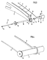
- Ein nach der Erfindung aufgebautes Vordach in perspektivischer Darstellung mit Blick von oben,
- Fig. 2
- Die gleiche Darstellung des Vordaches mit Blick von unten,
- Fig. 3
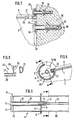
- Einen Ausschnitt des Vordaches mit dem traufseitigen Ende des Haltebügels vor dem Einführen des Glasdaches und Schließen des Haltesteges sowie den Mitteln zum Verschrauben der Regenrinne in einer Explosionszeichnung,
- Fig. 4
- Den gleichen Ausschnitt des Vordaches im zusammengebauten Zustand in perspektivischer Darstellung,
- Fig. 5
- Einen Querschnitt durch die Halteschale gemäß Linie V - V in
Figur 6 mit seitlich eingeführter Regenrinne und verrastetem Haltesteg, - Fig. 6
- Einen Längsschnitt durch das Regenrinnenprofil mit am Haltebügel angeschraubter Abdeckkappe gemäß Linie VI - VI in
Fig. 5 , - Fig. 7
- Einen Ausschnitt der an der Fassadenwand befestigten Vordach- halterung im Schnitt,
- Fig. 8
- Einen Querschnitt durch die Wandprofilschiene zur Aufnahme des Glasdaches mit Dichtungsprofil,
- Fig. 9
- Einen perspektivischen Ausschnitt der Wandprofilschiene, des Haltebügels und der Wandbefestigungselemente vor dem Zusammenbau in einer Explosionszeichnung,
- Fig.10
- Die gleiche perspektivische Darstellung mit an der Wand befestigtem Haltebügel beim Einschieben des Glasdaches und
- Fig. 11
- Die gleiche perspektivische Darstellung nach dem Einschieben des Glasdaches und Niederdrücken des Haltesteges.
- Wie aus den
Figuren 1 und 2 ersichtlich, besteht das Vordach im wesentlichen aus einer rechteckigen Dachplatte 1, welche vorzugsweise aus einem durchsichtigen Acrylglas hergestellt ist, sowie aus mindestens zwei plattenförmigen, mit ihrem freitragenden Ende abwärts geneigten Haltebügeln 2, welche als spitzwinkliges Dreieck ausgebildet sind und mit ihren breiteren Enden an einer Wand verankerter bar sind. - Die Oberkanten 3 der Haltebügel 2 sind bogenförmig ausgebildet. Parallel zu den Oberkanten 3 ist jeweils ein Schlitz 4 eingeschnitten und zwar in einer Breite b, welche der Dicke D der Dachplatte 1 entspricht. Der dabei herausgearbeitete Steg 5 ist bis kurz vor dem Ende der Haltebügel 2 so schmal ausgeschnitten, dass er sowohl auf seiner Länge als auch an seiner Verbindungsstelle biegsam ist.
- Das andere Ende des Steges 5 ist nach dem Einlegen der Dachplatte 1 und Niederdrücken des Steges 5 mit dem freien Ende des Haltebügels 2 in noch zu beschreibender Weise verbindbar.
- An das freie Ende des Haltebügels 2 schließt sich eine etwa über ¾ des Umfangs kreisringförmig ausgeschnittene Halteschale 6 an, in welche eine nach oben offene, ebenfalls über ¾ des Umfangs reichende Regenrinne 7, wie aus
Figur 3 ersichtlich, in Richtung des Pfeils R seitlich einführbar ist. Das freie Ende der Halteschale 6 ist mit einer Scheibe 8 einstückig verbunden, welche den Innenraum der Regenrinne 7 bis auf einen unteren, d.h. für den Wasserablauf freibleibenden Bereich 41 voll ausfüllt (Figur 3 ). - Hierbei ist der Durchmesser der Scheibe 8 dem Innendurchmesser der Rinnenwand 20 so angepasst, dass die Regenrinne 7 die Scheibe 8 bündig umschließt. Demgegenüber ist der Innendurchmesser der Halteschale 6 zweckmäßigerweise etwas größer bemessen als der Außendurchmesser der Rinnenwand 20, so dass zwischen Rinnenwand 20 und Halteschale 6 ein Spalt "S" frei bleibt. Dadurch wird beim seitlichen Einschieben der Regenrinne 7 vermieden, dass sich auf der Oberfläche der Rinnenwand 20 unschöne Kratzspuren bilden können (
Figur 5 ). - An dieser Scheibe 8 ist ein auf den Steg 5 weisender Vorsprung 9 angeformt, welcher in eine am freien Ende des bogenförmigen Steges 5 entsprechenden Aussparung 10 seitlich eingedrückt und - wie bei einem Puzzlespiel - in der Scheibenebene verrastet wird, wobei sich im verrasteten Zustand eine geschlossene Scheibe 8 ergibt (
Figur 3 u.5). - Die den Regenrinnenraum ausfüllenden Scheiben 8 sind mit je einer zentralen Bohrung 11 versehen. Zwischen den beiden Scheiben 8 lässt sich ein Rohr 12 positionieren, welches an beiden Enden mit einer Gewindehülse 13 versehen ist. Dieses Rohr 12, das auch als Welle ausgebildet sein kann, ist so bemessen, dass die Scheiben 8 im gleichen Abstand gehalten werden wie die Haltebügel 2 nach ihrer Verankerung an der Hauswand.
- Zur Fixierung der Scheiben 8 werden Schrauben 14 verwendet, deren Köpfe 15 in entsprechenden Aussparungen in Abdeckkappen 16 versenkbar sind. Diese Abdeckkappen 16 stützen sich ihrerseits auf den Stirnkanten 17 der Regenrinne 7 ab (
Figur 6 ) und dienen gleichzeitig zur seitlichen Fixierung der Dachplatte 1 (Fig.4 ). - Zwischen den Abdeckpappen 16 und den Scheiben 8 der Haltebügel 2 ist jeweils ein weiteres Abstandsrohr 18 vorgesehen, welches sich mit seinen Stirnseiten an den Abdeckkappen 16 und den Scheiben 8 abstützt. Durch die beiden seitlichen Abstandsrohre 18 werden die Schrauben 14, wie aus
Figur 6 ersichtlich, mit ihren Schäften 19 hindurchgeführt und dann in die Gewindehülsen 13 des mittleren Abstandsrohres 12 eingeschraubt. Hierdurch werden die Rinnenwand 20 der Regenrinne 7 zwischen den beiden Abdeckkappen 16 und gleichzeitig die Scheiben 8 zwischen den Abstandsrohren 12 und 18 fest eingespannt und außerdem die Dachplatte 1 seitlich fixiert. - Wie aus
Figur 5 weiter ersichtlich, ist an dem unter der Dachplatte 1 anliegenden Ende der Rinnenwand 20 eine Profilkante 21 mit einem U-förmigem Profilquerschnitt angeformt, welche in den Innenraum der Regenrinne 7 hineinragt und die untere freie Kante 22 der Dachplatte 1 allseits umfasst. Die Rinnenwand 20 ist hierbei im vorliegenden Ausführungsbeispiel mindestens an einem Ende dicht vor der Abdeckkappe 16 in ihrem unteren Wandbereich mit einer Abflussöffnung 23 für das Regenwasser versehen (Figur 6 ). Anstelle dieser Abflussöffnung 23 in der Regenrinne 7 ist es auch machbar und von den Herstellungskosten sogar günstiger, eine Aussparung im unteren Bereich der Abdeckkappe 16 vorzusehen. - Wie aus
Figur 7 ersichtlich, lässt sich die wandseitige Kante 24 der Dachplatte 1 über ein Winkelprofil 25 mit der Fassadenwand 26 wasserdicht verbinden. Das Winkelprofil 25 ist hierzu so ausgebildet, dass zwei von der Wand 26 etwa rechtwinklig abstehende Schenkel 27 und 28 die Plattenkante 24 U-förmig umfassen. An dem an der Wand anliegenden Schenkel 29 ist eine Rinne 30 zur Aufnahme eines elastisch deformierbaren Dichtungsprofils 31 aus Gummi oder ähnlich elastischem PVC-Material eingelassen. - Die beiden Schenkel 27 und 28 weisen hierbei Schlitze 32 auf, welche der Dicke der Haltebügel 2 entsprechen und bis auf den Abstand "a" an den Wandschenkel 29 heranreichen. Desgleichen sind am oberen Ende der Kanten 33 beider Haltebügel 2 Einschnitte 40 vorgesehen, deren Tiefen "t" den Abständen "a" bei den Schlitzen 32 entsprechen. Dadurch wird erreicht, dass beim Einschieben der Haltebügel 2 in die Schlitze 32 die wandseitigen Kanten 33 mit ihrem Einschnitt 40 die beiden Schenkel 27 und 28 um den Abstand "a" übergreifen, wodurch sich ein fester Verbund zwischen Haltebügel 2 und Wandprofil 25 ergibt.
- Zur Verankerung der Haltebügel 2 an der Fassadenwand 26 sind an deren Kanten 33 rechtwinklig abstehende Befestigungsschenkel 34 mit Befestigungslöchern 35 angeformt, welche mittels Schrauben 36 und Dübel 37 in bekannter Weise in der Wand 26 befestigt werden. Vorher werden zuerst die Winkelprofile 25 mittels Schrauben 38 und Dübel 39 in der vorbestimmten Höhe an der Fassadenwand 26 befestigt, wobei das in die Rinne 30 eingelegte Dichtungsprofil 31, wie aus
Figur 7 ersichtlich, zusammengedrückt wird. - In den
Figuren 9 bis 11 ist der Montageablauf bei der Anbringung der Vordachhalterung nachFigur 7 anschaulich dargestellt. - Nach dem Einlegen des Dichtungsprofils 31 in die Rinne 30 des Winkelprofils 25 wird dieses an der vorbestimmten Stelle an der Fassadenwand 26 angeschraubt. Als nächstes werden die Haltebügel 2 mir ihren Kanten 33 in die Aussparungen 32 der Schenkel 27 und 28 bis zur Anlage an den wandseitigen Schenkel 29 eingeführt und mit ihren Befestigungsschenkeln 34 an der Wand 26 mittels der Schrauben 36 und Dübel 37 fest verankert. Sodann wird die Dachplatte 1 unter dem etwas hochgebogenen Steg 5 in den Schlitz 4 eingeführt und in Richtung des Pfeils "M" soweit vorgeschoben, bis die Hinterkante 24 der Dachplatte 1 zwischen den beiden Schenkeln 27 und 28 des Winkelprofils 25 voll eingetaucht ist.
- Nun folgt die Befestigung der Regenrinne 7 am traufseitigen Ende der Haltebügel 2, wie im einzelnen aus den
Figuren 3 bis 6 zu ersehen ist. Die Regenrinne 7 wird zunächst an einem Ende der Dachplatte 1 mit der Profilkante 21 auf die Vorderkante 22 aufgedrückt und dann seitlich über die Scheiben 8 der Haltebügel 2 soweit verschoben, bis die Stirnkanten 17 der Regenrinne 7 an beiden Enden gleich weit über die Haltebügel 2 hinausragen. Sodann wird die eine Schraube 14 durch die Abdeckkappe 16, das seitliche Abstandsrohr 18 sowie die Bohrung 11 in der Scheibe 8 hindurch gesteckt und in die Gewindehülse 13 des mittleren Abstandsrohres 12 eingeschraubt, welches vorher zwischen den beiden Haltebügeln 2 von oben in die Regenrinne 7 eingelegt worden ist. Die Abdeckkappe 16 wird bei der Gelegenheit fest an die Stirnkante 17 der Rinnenwand 20 angezogen. - Jetzt wird am anderen Ende der Regenrinne 7 ebenfalls die zweite Schraube 14 zusammen mit der Abdeckkappe 16 und dem seitlichen Abstandsrohr 19 in die Bohrung 11 der anderen Scheibe 8 eingeführt und in die Gewindehülse 13 am anderen Ende des mittleren Abstandsrohres 12 eingeschraubt, bis die Abdeckkappe 16 fest an der Stirnkante 17 der Regenrinne 7 anliegt. Zum Schluss werden dann noch die Stege 5 auf die Dachplatte 1 niedergedrückt und die Aussparungen 10 von der Seite her auf die Vorsprünge 9 an den Scheiben 8 aufgedrückt, wobei sie sich, wie aus
Figur 4 ersichtlich, wie bei einem Puzzlespiel ineinander verrasten. Damit ist der Montagevorgang erfolgreich beendet. -
- 1
- Dachplatte
- 2
- Haltebügel
- 3
- Oberkante
- 4
- Schlitz
- 5
- Steg
- 6
- Halteschale
- 7
- Regenrinne
- 8
- Scheibe
- 9
- Vorsprung
- 10
- Aussparung
- 11
- Zentrale Bohrung
- 12
- Mittleres Abstandsrohr
- 13
- Gewindehülse
- 14
- Schrauben
- 15
- Schraubenköpfe
- 16
- Abdeckkappen
- 17
- Stirnkanten
- 18
- Seitliche Abstandsrohre
- 19
- Schraubenschaft
- 20
- Rinnenwand
- 21
- Profilkante
- 22
- Vorderkante der Dachplatte
- 23
- Abflussöffnung
- 24
- Hinterkante der Dachplatte
- 25
- Winkelprofil
- 26
- Fassadenwand
- 27
- Oberschenkel
- 28
- Unterschenkel
- 29
- Wandschenkel
- 30
- Schenkelrinne
- 31
- Dichtungsprofil
- 32
- Schlitze
- 33
- Kante des Haltebügels
- 34
- Befestigungsschenkel
- 35
- Befestigungslöcher
- 36
- Schrauben
- 37
- Dübel
- 38
- Schrauben
- 39
- Dübel
- 40
- Einschnitt
- 41
- Scheibenfreibereich
Claims (13)
- Freitragendes Vordach, bestehend aus einer rechteckigen Dachplatte (1) sowie mindestens zwei plattenförmigen, abwärts geneigten Haltebügeln (2), welche als spitzwinkliges Dreieck ausgebildet sind und mit ihrem breiteren Ende an einer Wand veranker bar sind,
dadurch gekennzeichnet,• dass die Oberkanten (3) der Haltebügel (2) bogenförmig ausgebildet sind,• dass parallel zu den Oberkanten (3) jeweils ein Schlitz (4) in einer Breite (b) entsprechend der Dicke (D) der Dachplatte (1) bis kurz vor dem wandseitigen Ende der Haltebügel (2) eingeschnitten ist, so dass der dabei herausgearbeitete Steg (5) sowohl auf seiner ganzen Länge als auch an der wandseitigen Verbindung mit dem Haltebügel (2) biegsam ist,• dass das andere, nämlich traufseitige Ende nach dem Einlegen der Dachplatte (1) und Niederdrücken des Steges (5) mit dem traufseitigen Ende des Haltebügels (2) verbindbar ist,• und dass sich an das traufseitige Ende der Haltebügel (2) eine Halteschale (6) anschließt, in welche eine nach oben offene Regenrinne (7) seitlich einführbar ist. - Vordach nach Anspruch 1, dadurch gekennzeichnet, dass die Halteschale (6) etwa über ¾ des Umfangs kreisringförmig ausgeschnitten ist und die Regenrinne (7) im Querschnitt ebenfalls über ¾ des Umfangs als Kreisring ausgebildet ist.
- Vordach nach Anspruch 1 oder 2, dadurch gekennzeichnet, dass das freie Ende jeder Halteschale (6) mit einer den Rinnenquerschnitt der Regenrinne (7) bis auf einen unteren Bereich ausfüllenden Scheibe (8) einstückig verbunden ist und diese Scheibe (8) einen auf das Ende des Steges (5) weisenden, angeformten Vorsprung (9) aufweist, welcher in eine dem Vorsprung (9) entsprechende Aussparung (10) am traufseitigen Ende des bogenförmigen Steges (5) seitlich eindrückbar und und damit der Steg (5) in der Scheibenebene verrastbar ist.
- Vordach nach Anspruch 3, dadurch gekennzeichnet, dass die den Rinnenquerschnitt überwiegend ausfüllenden Scheiben (8) an den Halteschalen (6) mit je einer zentralen Bohrung (11) versehen sind und durch ein Rohr (12) im gleichen Abstand wie der bei der wandseitigen Verankerung der Haltebügel (2) vorgesehene Abstand gehalten werden.
- Vordach nach Anspruch 4, dadurch gekennzeichnet, dass Köpfe (15) vonSchrauben (14) in Abdeckkappen (16) eingelagert sind, welche sich ihrerseits auf den Stirnkanten (17) der Rinnenwand (20) abstützen, wobei das Abstandsrohr (12) an beiden Enden eine Gewindehülse (13) aufweist
- Vordach nach Anspruch 5, dadurch gekennzeichnet, dass zwischen den Abdeckkappen (16) und den Scheiben (8) der Halteschalen (6) jeweils ein weiteres Abstandsrohr (18) vorgesehen ist, durch welches die Schraube (14) mit ihrem Schaft (19) hindurchgeführt wird.
- Vordach nach einem der Ansprüche 1 bis 6, dadurch gekennzeichnet, dass an dem unter der Dachplatte (1) anliegenden Ende der Rinnenwand (20) eine Profilkante (21) mit einem U-förmigen Profilquerschnitt angeformt ist, welche in den Innenraum der Regenrinne (7) hineinragt und die untere traufseitige Kante (22) der Dachplatte (1) allseits umfasst.
- Vordach nach einem der Ansprüche 1 bis 7, dadurch gekennzeichnet, dass die Rinnenwand (20) mindestens an einem Ende dicht vor der Abdeckkappe (16) in ihrem unteren Bereich mit einer Abflussöffnung (23) für das Regenwasser versehen ist.
- Vordach nach einem der Ansprüche 1 bis 8, dadurch gekennzeichnet, dass die wandseitige Plattenkante (24) der Dachplatte (1) über ein Winkelprofil (25) mit der Wand (26) wasserdicht verbindbar ist.
- Vordach nach Anspruch 9, dadurch gekennzeichnet, dass bei dem Winkelprofil (25) zwei von der Wand etwa rechtwinklig abstehende Schenkel (27, 28) die Plattenkante (24) U-förmig umfassen und in dem an der Wand anliegenden Schenkel (29) eine Rinne (30) zur Aufnahme eines elastisch deformierbaren Dichtungsprofils (31) eingelassen ist.
- Vordach nach Anspruch 9 oder 10, dadurch gekennzeichnet, dass in den beiden Schenkeln (27) und (28) Schlitze (32) zum Einschieben der wandseitigen Kanten (33) der Haltebügel (2) eingeschnitten sind.
- Vordach nach Anspruch 11, dadurch gekennzeichnet, dass die Schlitze bis auf einen Abstand "a" an den Wandschenkel (29) heranreichen.
- Vordach nach Anspruch 12, dadurch gekennzeichnet, dass am oberen Ende der Kanten (33) der Haltebügel (2) Aussparungen (40) vorgesehen sind, deren Tiefen "t" den Abständen "a" bei den Schlitzen (33) entsprechen
Applications Claiming Priority (2)
| Application Number | Priority Date | Filing Date | Title |
|---|---|---|---|
| DE10359089A DE10359089B3 (de) | 2003-12-17 | 2003-12-17 | Freitragendes Vordach |
| DE10359089 | 2003-12-17 |
Publications (3)
| Publication Number | Publication Date |
|---|---|
| EP1544373A2 EP1544373A2 (de) | 2005-06-22 |
| EP1544373A3 EP1544373A3 (de) | 2007-01-31 |
| EP1544373B1 true EP1544373B1 (de) | 2009-03-11 |
Family
ID=34442522
Family Applications (1)
| Application Number | Title | Priority Date | Filing Date |
|---|---|---|---|
| EP04026761A Expired - Lifetime EP1544373B1 (de) | 2003-12-17 | 2004-11-11 | Freitragendes Vordach |
Country Status (3)
| Country | Link |
|---|---|
| EP (1) | EP1544373B1 (de) |
| AT (1) | ATE425319T1 (de) |
| DE (2) | DE10359089B3 (de) |
Families Citing this family (8)
| Publication number | Priority date | Publication date | Assignee | Title |
|---|---|---|---|---|
| DE102006019755B4 (de) * | 2006-04-28 | 2013-11-14 | Pusch Gmbh & Co. Kg | Freitragendes Vordach |
| KR101028857B1 (ko) * | 2008-07-09 | 2011-04-12 | 안종현 | 옥외 차양용 브라켓트 |
| KR101028861B1 (ko) * | 2008-07-10 | 2011-04-12 | 안종현 | 아치형 차양용 브라켓트와 이를 이용한 아치형 차양 |
| KR200453447Y1 (ko) | 2009-03-11 | 2011-05-09 | 정영미 | 차양장치 |
| IT1395693B1 (it) * | 2009-10-02 | 2012-10-19 | Properzi | Pensilina modulare componibile . |
| DE202011000120U1 (de) | 2011-01-17 | 2012-04-18 | Pauli + Sohn Gmbh Metallwaren | Vordach |
| KR200465258Y1 (ko) * | 2011-03-14 | 2013-02-08 | 정영미 | 밴딩파이프를 사용하는 차양 조립장치 |
| CN113152807B (zh) * | 2021-04-08 | 2022-08-26 | 中建铁路投资建设集团有限公司 | 一种圆拱形双曲线雨棚结构的施工方法 |
Family Cites Families (3)
| Publication number | Priority date | Publication date | Assignee | Title |
|---|---|---|---|---|
| US3138832A (en) * | 1962-09-06 | 1964-06-30 | Lawrence J Gonnello | Awning |
| DE20017167U1 (de) * | 2000-10-06 | 2000-12-28 | Ariane Aluminiumsysteme Gmbh | Vordachanordnung |
| DE20105114U1 (de) * | 2001-03-23 | 2001-09-27 | Balustrada H.P.I. Edelstahl Design GmbH, 36124 Eichenzell | Vollständig verschraubtes Vordach |
-
2003
- 2003-12-17 DE DE10359089A patent/DE10359089B3/de not_active Expired - Fee Related
-
2004
- 2004-11-11 EP EP04026761A patent/EP1544373B1/de not_active Expired - Lifetime
- 2004-11-11 DE DE502004009124T patent/DE502004009124D1/de not_active Expired - Lifetime
- 2004-11-11 AT AT04026761T patent/ATE425319T1/de active
Also Published As
| Publication number | Publication date |
|---|---|
| ATE425319T1 (de) | 2009-03-15 |
| EP1544373A3 (de) | 2007-01-31 |
| EP1544373A2 (de) | 2005-06-22 |
| DE10359089B3 (de) | 2005-05-19 |
| DE502004009124D1 (de) | 2009-04-23 |
Similar Documents
| Publication | Publication Date | Title |
|---|---|---|
| EP0921252A2 (de) | Befestigungselement zur Abstandsbefestigung von Latten, Profilen, Platten oder dergleichen an einem festen Untergrund, Hilfsvorrichtung zum Bohren von Löchern in einem Untergrund zum Einsetzen der Befestigungselemente sowie Verfahren zur Abstandsbefestigung unter Einsatz eines solchen Befestigungselementes | |
| CH699766B1 (de) | Rahmenanschlussteil zur Befestigung an einem Rahmen. | |
| EP1849929B1 (de) | Freitragendes Vordach | |
| DE202007004760U1 (de) | Freitragendes Vordach | |
| DE10359089B3 (de) | Freitragendes Vordach | |
| DE10361751A1 (de) | Dämmfassadendübel | |
| EP1965001B1 (de) | Bekleidungssystem für Bauwerke mit zweidimensional und/oder sphärisch geformten, zu bekleidenden Bereichen | |
| EP0918127B1 (de) | Türfutter und Montagevorrichtung | |
| EP0555214A1 (de) | Dach bzw. fassade insbesondere eines wintergartens | |
| DE19822103A1 (de) | Fassadensystem für die Verkleidung eines Bauwerkes | |
| DE3635167C2 (de) | ||
| DE20319544U1 (de) | Freitragende Vordachhalterung | |
| DE202017006664U1 (de) | Überdachungsvorrichtung | |
| DE2151339A1 (de) | Hohlprofil fuer blendrahmen | |
| DE3221615A1 (de) | Wandanschluss-klemmprofil | |
| DE102017207494B4 (de) | Montagevorrichtung und Montageverfahren für Wand- oder Dachtafeln mit wellenartigem oder trapezartigem Querschnitt | |
| EP1630319B1 (de) | Freitragende Seitenblende | |
| DE2428003C2 (de) | Dichtungsprofil für unterhalb von Fenstersohlbanken, Artiken o.dgl. befindliche Horizontalfugen | |
| DE9113591U1 (de) | Befestigungselement für Rohrschellen | |
| DE102016216212A1 (de) | Überdachungsvorrichtung und Verfahren zur Herstellung einer Überdachungsvorrichtung | |
| DE7219803U (de) | Fensterzarge | |
| DE20309898U1 (de) | Entwässerungsbauelement | |
| DE8216635U1 (de) | Wandanschluß-Klemmprofil | |
| DE102005001801A1 (de) | Stossverbinder zum winkeligen Verbinden von Hohlprofilen | |
| EP3770353A1 (de) | Dichtungsspange, längsträgeranordnung und verfahren zur abdichtung eines stossbereichs |
Legal Events
| Date | Code | Title | Description |
|---|---|---|---|
| PUAI | Public reference made under article 153(3) epc to a published international application that has entered the european phase |
Free format text: ORIGINAL CODE: 0009012 |
|
| AK | Designated contracting states |
Kind code of ref document: A2 Designated state(s): AT BE BG CH CY CZ DE DK EE ES FI FR GB GR HU IE IS IT LI LU MC NL PL PT RO SE SI SK TR |
|
| AX | Request for extension of the european patent |
Extension state: AL HR LT LV MK YU |
|
| PUAL | Search report despatched |
Free format text: ORIGINAL CODE: 0009013 |
|
| AK | Designated contracting states |
Kind code of ref document: A3 Designated state(s): AT BE BG CH CY CZ DE DK EE ES FI FR GB GR HU IE IS IT LI LU MC NL PL PT RO SE SI SK TR |
|
| AX | Request for extension of the european patent |
Extension state: AL HR LT LV MK YU |
|
| 17P | Request for examination filed |
Effective date: 20070227 |
|
| AKX | Designation fees paid |
Designated state(s): AT BE BG CH CY CZ DE DK EE ES FI FR GB GR HU IE IS IT LI LU MC NL PL PT RO SE SI SK TR |
|
| GRAP | Despatch of communication of intention to grant a patent |
Free format text: ORIGINAL CODE: EPIDOSNIGR1 |
|
| GRAS | Grant fee paid |
Free format text: ORIGINAL CODE: EPIDOSNIGR3 |
|
| GRAA | (expected) grant |
Free format text: ORIGINAL CODE: 0009210 |
|
| AK | Designated contracting states |
Kind code of ref document: B1 Designated state(s): AT BE BG CH CY CZ DE DK EE ES FI FR GB GR HU IE IS IT LI LU MC NL PL PT RO SE SI SK TR |
|
| REG | Reference to a national code |
Ref country code: GB Ref legal event code: FG4D Free format text: NOT ENGLISH |
|
| REG | Reference to a national code |
Ref country code: CH Ref legal event code: EP |
|
| REG | Reference to a national code |
Ref country code: IE Ref legal event code: FG4D Free format text: LANGUAGE OF EP DOCUMENT: GERMAN |
|
| REF | Corresponds to: |
Ref document number: 502004009124 Country of ref document: DE Date of ref document: 20090423 Kind code of ref document: P |
|
| REG | Reference to a national code |
Ref country code: CH Ref legal event code: NV Representative=s name: BOVARD AG PATENTANWAELTE |
|
| PG25 | Lapsed in a contracting state [announced via postgrant information from national office to epo] |
Ref country code: SI Free format text: LAPSE BECAUSE OF FAILURE TO SUBMIT A TRANSLATION OF THE DESCRIPTION OR TO PAY THE FEE WITHIN THE PRESCRIBED TIME-LIMIT Effective date: 20090311 Ref country code: NL Free format text: LAPSE BECAUSE OF FAILURE TO SUBMIT A TRANSLATION OF THE DESCRIPTION OR TO PAY THE FEE WITHIN THE PRESCRIBED TIME-LIMIT Effective date: 20090311 Ref country code: FI Free format text: LAPSE BECAUSE OF FAILURE TO SUBMIT A TRANSLATION OF THE DESCRIPTION OR TO PAY THE FEE WITHIN THE PRESCRIBED TIME-LIMIT Effective date: 20090311 |
|
| NLV1 | Nl: lapsed or annulled due to failure to fulfill the requirements of art. 29p and 29m of the patents act | ||
| PG25 | Lapsed in a contracting state [announced via postgrant information from national office to epo] |
Ref country code: SE Free format text: LAPSE BECAUSE OF FAILURE TO SUBMIT A TRANSLATION OF THE DESCRIPTION OR TO PAY THE FEE WITHIN THE PRESCRIBED TIME-LIMIT Effective date: 20090611 Ref country code: PL Free format text: LAPSE BECAUSE OF FAILURE TO SUBMIT A TRANSLATION OF THE DESCRIPTION OR TO PAY THE FEE WITHIN THE PRESCRIBED TIME-LIMIT Effective date: 20090311 |
|
| REG | Reference to a national code |
Ref country code: IE Ref legal event code: FD4D |
|
| PG25 | Lapsed in a contracting state [announced via postgrant information from national office to epo] |
Ref country code: PT Free format text: LAPSE BECAUSE OF FAILURE TO SUBMIT A TRANSLATION OF THE DESCRIPTION OR TO PAY THE FEE WITHIN THE PRESCRIBED TIME-LIMIT Effective date: 20090824 Ref country code: CZ Free format text: LAPSE BECAUSE OF FAILURE TO SUBMIT A TRANSLATION OF THE DESCRIPTION OR TO PAY THE FEE WITHIN THE PRESCRIBED TIME-LIMIT Effective date: 20090311 Ref country code: EE Free format text: LAPSE BECAUSE OF FAILURE TO SUBMIT A TRANSLATION OF THE DESCRIPTION OR TO PAY THE FEE WITHIN THE PRESCRIBED TIME-LIMIT Effective date: 20090311 Ref country code: ES Free format text: LAPSE BECAUSE OF FAILURE TO SUBMIT A TRANSLATION OF THE DESCRIPTION OR TO PAY THE FEE WITHIN THE PRESCRIBED TIME-LIMIT Effective date: 20090622 Ref country code: IE Free format text: LAPSE BECAUSE OF FAILURE TO SUBMIT A TRANSLATION OF THE DESCRIPTION OR TO PAY THE FEE WITHIN THE PRESCRIBED TIME-LIMIT Effective date: 20090311 |
|
| PG25 | Lapsed in a contracting state [announced via postgrant information from national office to epo] |
Ref country code: IS Free format text: LAPSE BECAUSE OF FAILURE TO SUBMIT A TRANSLATION OF THE DESCRIPTION OR TO PAY THE FEE WITHIN THE PRESCRIBED TIME-LIMIT Effective date: 20090711 Ref country code: RO Free format text: LAPSE BECAUSE OF FAILURE TO SUBMIT A TRANSLATION OF THE DESCRIPTION OR TO PAY THE FEE WITHIN THE PRESCRIBED TIME-LIMIT Effective date: 20090311 Ref country code: SK Free format text: LAPSE BECAUSE OF FAILURE TO SUBMIT A TRANSLATION OF THE DESCRIPTION OR TO PAY THE FEE WITHIN THE PRESCRIBED TIME-LIMIT Effective date: 20090311 |
|
| PLBE | No opposition filed within time limit |
Free format text: ORIGINAL CODE: 0009261 |
|
| STAA | Information on the status of an ep patent application or granted ep patent |
Free format text: STATUS: NO OPPOSITION FILED WITHIN TIME LIMIT |
|
| PG25 | Lapsed in a contracting state [announced via postgrant information from national office to epo] |
Ref country code: DK Free format text: LAPSE BECAUSE OF FAILURE TO SUBMIT A TRANSLATION OF THE DESCRIPTION OR TO PAY THE FEE WITHIN THE PRESCRIBED TIME-LIMIT Effective date: 20090311 Ref country code: BG Free format text: LAPSE BECAUSE OF FAILURE TO SUBMIT A TRANSLATION OF THE DESCRIPTION OR TO PAY THE FEE WITHIN THE PRESCRIBED TIME-LIMIT Effective date: 20090611 |
|
| 26N | No opposition filed |
Effective date: 20091214 |
|
| BERE | Be: lapsed |
Owner name: PUSCH G.M.B.H. & CO. KG Effective date: 20091130 |
|
| PG25 | Lapsed in a contracting state [announced via postgrant information from national office to epo] |
Ref country code: MC Free format text: LAPSE BECAUSE OF NON-PAYMENT OF DUE FEES Effective date: 20091130 |
|
| GBPC | Gb: european patent ceased through non-payment of renewal fee |
Effective date: 20091111 |
|
| REG | Reference to a national code |
Ref country code: FR Ref legal event code: ST Effective date: 20100730 |
|
| PG25 | Lapsed in a contracting state [announced via postgrant information from national office to epo] |
Ref country code: GR Free format text: LAPSE BECAUSE OF FAILURE TO SUBMIT A TRANSLATION OF THE DESCRIPTION OR TO PAY THE FEE WITHIN THE PRESCRIBED TIME-LIMIT Effective date: 20090612 Ref country code: BE Free format text: LAPSE BECAUSE OF NON-PAYMENT OF DUE FEES Effective date: 20091130 Ref country code: FR Free format text: LAPSE BECAUSE OF NON-PAYMENT OF DUE FEES Effective date: 20091130 |
|
| PG25 | Lapsed in a contracting state [announced via postgrant information from national office to epo] |
Ref country code: GB Free format text: LAPSE BECAUSE OF NON-PAYMENT OF DUE FEES Effective date: 20091111 |
|
| PG25 | Lapsed in a contracting state [announced via postgrant information from national office to epo] |
Ref country code: IT Free format text: LAPSE BECAUSE OF FAILURE TO SUBMIT A TRANSLATION OF THE DESCRIPTION OR TO PAY THE FEE WITHIN THE PRESCRIBED TIME-LIMIT Effective date: 20090311 |
|
| REG | Reference to a national code |
Ref country code: CH Ref legal event code: PFA Owner name: PUSCH GMBH & CO. KG Free format text: PUSCH GMBH & CO. KG#BACHSTRASSE 6#56242 MARIENRACHDORF (DE) -TRANSFER TO- PUSCH GMBH & CO. KG#BACHSTRASSE 6#56242 MARIENRACHDORF (DE) |
|
| PG25 | Lapsed in a contracting state [announced via postgrant information from national office to epo] |
Ref country code: LU Free format text: LAPSE BECAUSE OF NON-PAYMENT OF DUE FEES Effective date: 20091111 |
|
| PG25 | Lapsed in a contracting state [announced via postgrant information from national office to epo] |
Ref country code: HU Free format text: LAPSE BECAUSE OF FAILURE TO SUBMIT A TRANSLATION OF THE DESCRIPTION OR TO PAY THE FEE WITHIN THE PRESCRIBED TIME-LIMIT Effective date: 20090912 |
|
| PG25 | Lapsed in a contracting state [announced via postgrant information from national office to epo] |
Ref country code: TR Free format text: LAPSE BECAUSE OF FAILURE TO SUBMIT A TRANSLATION OF THE DESCRIPTION OR TO PAY THE FEE WITHIN THE PRESCRIBED TIME-LIMIT Effective date: 20090311 |
|
| PG25 | Lapsed in a contracting state [announced via postgrant information from national office to epo] |
Ref country code: CY Free format text: LAPSE BECAUSE OF FAILURE TO SUBMIT A TRANSLATION OF THE DESCRIPTION OR TO PAY THE FEE WITHIN THE PRESCRIBED TIME-LIMIT Effective date: 20090311 |
|
| PGFP | Annual fee paid to national office [announced via postgrant information from national office to epo] |
Ref country code: CH Payment date: 20150127 Year of fee payment: 11 |
|
| PGFP | Annual fee paid to national office [announced via postgrant information from national office to epo] |
Ref country code: AT Payment date: 20150122 Year of fee payment: 11 |
|
| REG | Reference to a national code |
Ref country code: DE Ref legal event code: R082 Ref document number: 502004009124 Country of ref document: DE Representative=s name: HANNKE BITTNER & PARTNER, DE Ref country code: DE Ref legal event code: R081 Ref document number: 502004009124 Country of ref document: DE Owner name: HORST WELLNESS GMBH & CO. KG, DE Free format text: FORMER OWNER: PUSCH GMBH & CO. KG, 56242 MARIENRACHDORF, DE Ref country code: DE Ref legal event code: R082 Ref document number: 502004009124 Country of ref document: DE Representative=s name: VON ROHR PATENTANWAELTE PARTNERSCHAFT MBB, DE |
|
| REG | Reference to a national code |
Ref country code: CH Ref legal event code: PUE Owner name: HORST WELNESS GMBH AND CO. KG, DE Free format text: FORMER OWNER: PUSCH GMBH AND CO. KG, DE |
|
| REG | Reference to a national code |
Ref country code: DE Ref legal event code: R082 Ref document number: 502004009124 Country of ref document: DE Representative=s name: VON ROHR PATENTANWAELTE PARTNERSCHAFT MBB, DE |
|
| REG | Reference to a national code |
Ref country code: CH Ref legal event code: PK Free format text: BERICHTIGUNG INHABER |
|
| REG | Reference to a national code |
Ref country code: CH Ref legal event code: PL |
|
| REG | Reference to a national code |
Ref country code: AT Ref legal event code: MM01 Ref document number: 425319 Country of ref document: AT Kind code of ref document: T Effective date: 20151111 |
|
| PG25 | Lapsed in a contracting state [announced via postgrant information from national office to epo] |
Ref country code: LI Free format text: LAPSE BECAUSE OF NON-PAYMENT OF DUE FEES Effective date: 20151130 Ref country code: CH Free format text: LAPSE BECAUSE OF NON-PAYMENT OF DUE FEES Effective date: 20151130 |
|
| PG25 | Lapsed in a contracting state [announced via postgrant information from national office to epo] |
Ref country code: AT Free format text: LAPSE BECAUSE OF NON-PAYMENT OF DUE FEES Effective date: 20151111 |
|
| PGFP | Annual fee paid to national office [announced via postgrant information from national office to epo] |
Ref country code: DE Payment date: 20171121 Year of fee payment: 14 |
|
| REG | Reference to a national code |
Ref country code: DE Ref legal event code: R119 Ref document number: 502004009124 Country of ref document: DE |
|
| PG25 | Lapsed in a contracting state [announced via postgrant information from national office to epo] |
Ref country code: DE Free format text: LAPSE BECAUSE OF NON-PAYMENT OF DUE FEES Effective date: 20190601 |