EP1625771B1 - Procede pour chauffer des composants - Google Patents
Procede pour chauffer des composants Download PDFInfo
- Publication number
- EP1625771B1 EP1625771B1 EP04728098A EP04728098A EP1625771B1 EP 1625771 B1 EP1625771 B1 EP 1625771B1 EP 04728098 A EP04728098 A EP 04728098A EP 04728098 A EP04728098 A EP 04728098A EP 1625771 B1 EP1625771 B1 EP 1625771B1
- Authority
- EP
- European Patent Office
- Prior art keywords
- laser
- component
- heating
- turbine blade
- heated
- Prior art date
- Legal status (The legal status is an assumption and is not a legal conclusion. Google has not performed a legal analysis and makes no representation as to the accuracy of the status listed.)
- Expired - Fee Related
Links
Images


Classifications
-
- F—MECHANICAL ENGINEERING; LIGHTING; HEATING; WEAPONS; BLASTING
- F27—FURNACES; KILNS; OVENS; RETORTS
- F27D—DETAILS OR ACCESSORIES OF FURNACES, KILNS, OVENS, OR RETORTS, IN SO FAR AS THEY ARE OF KINDS OCCURRING IN MORE THAN ONE KIND OF FURNACE
- F27D99/00—Subject matter not provided for in other groups of this subclass
- F27D99/0001—Heating elements or systems
-
- H—ELECTRICITY
- H05—ELECTRIC TECHNIQUES NOT OTHERWISE PROVIDED FOR
- H05B—ELECTRIC HEATING; ELECTRIC LIGHT SOURCES NOT OTHERWISE PROVIDED FOR; CIRCUIT ARRANGEMENTS FOR ELECTRIC LIGHT SOURCES, IN GENERAL
- H05B3/00—Ohmic-resistance heating
- H05B3/0033—Heating devices using lamps
- H05B3/0038—Heating devices using lamps for industrial applications
Definitions
- the invention relates to a method for heating components before and / or during further processing thereof in the form of a laser build-up welding.
- Components such as turbine blades of gas turbines, must be heated in the production and maintenance of the same to carry out a variety of machining processes. This warming is also known as preheating.
- build-up welding In the maintenance of turbine blades, for example, so-called build-up welding is used.
- build-up welding the preheating of the turbine blades to be welded to a desired process temperature is required. Only when the turbine blade to be welded has been heated to the process temperature and maintained at the desired process temperature during build-up welding can reliable surfacing be performed.
- inductive systems are used for heating or for preheating of components.
- Such inductive systems may be, for example, coils that heat the component based on inductive energy input.
- the heating or preheating of components by means of inductive systems has the disadvantage that when heated or preheating high temperature tolerances of up to 50 ° C can be set on the component to be heated. This inaccurate temperature distribution on the component to be heated is disadvantageous.
- inductive systems consume a great deal of energy.
- Another disadvantage of inductive systems is that higher temperatures can occur in the interior of the component during heating or preheating than at the surface of the component. This can lead to damage to the component.
- the document DE 197 20 652 A relates to a heating device and a method for heating a component.
- a heat source for generating a locally different heat input is proposed in a component.
- the heating source preferably has a plurality of radiation sources, in particular for heat radiation differently adjustable radiation power, the radiation sources should preferably be heating elements.
- a preheating by means of high-energy laser, electron and plasma jets is conceivable, but it is noted that a uniform heating is problematic, and there is a risk of local melting.
- a ceramic thermal barrier coating is to be applied to the warm component.
- the document US-A-5,701,669 Protects a process for repairing turbine blades by buildup welding to restore the desired blade length.
- a kind of mold made of sheet metal strips is fixed to a worn blade tip, which forms the weld and limits.
- the mold is fixed with injection-molded plastic.
- the welding process is preferably laser powder buildup welding. A component preheating is not provided for in this document.
- the present invention is based on the problem to provide a novel method for heating components, which are subjected to a laser cladding.
- At least one laser device is used for heating as an energy source, wherein a separate laser device is used for laser buildup welding.
- laser devices By using laser devices to heat the component, a faster heating is achieved than in known from the prior art heating method. Furthermore, the use of laser devices ensures that no higher temperatures occur within the component to be heated than at its surfaces. Furthermore, laser devices have radiant energy with a narrow specific wavelength. As this provides for a defined energy input to the component and affects the result of the heating of the component advantageous.
- setting angles with which the laser beams strike the or each surface of the component to be heated are adapted to the contour of the corresponding surface.
- the homogeneity of the energy input is improved, especially in components such as turbine blades, which have different curved surfaces.
- the heating of the component is measured and depending on the heating is controlled so that the performance of the or each laser device is adjusted to Erzeilung a desired temperature setpoint. This ensures compliance with the desired temperature setpoint, which is particularly advantageous if during the processing of the component of the temperature setpoint heating for a longer period should be met.
- Fig. 1 to 3 each show different embodiments of the method according to the invention.
- Fig. 1 shows very schematically a turbine blade 10 of a high-pressure turbine of an aircraft engine. It is now within the meaning of the present invention to heat the turbine blade 10 of the high-pressure turbine before and / or during further processing thereof. In the further processing of the turbine blade 10 may be, for example, so-called build-up welding.
- At least one laser device is used as the energy source for heating or preheating the component.
- laser devices diode lasers are preferably used. The use of the diode laser is particularly advantageous. Alternatively or in addition to the diode lasers, however, other sources of laser radiation can also be used as energy sources. Exemplary here called CO 2 laser, Nd laser, YAG laser or Eximer laser.
- the turbine blade 10 to be heated is irradiated on two sides by the laser devices. This means that from two irradiation directions radiant energy to the turbine blade 10 to be heated or on the corresponding surfaces thereof is directed. So shows Fig. 1
- the first arrows 11 visualize the irradiation of the turbine blade 10 to be heated from a first irradiation direction
- the second arrows 12 visualize the irradiation thereof from a second irradiation direction.
- the two directions of irradiation in the direction of the arrows 11 and 12 serve for the irradiation of two different surfaces of the turbine blade 10. Due to the laser radiation, the turbine blade 10 is heated.
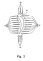
- the turbine blade 10 is irradiated from four directions. So shows Fig. 2 first arrows 13, second arrows 14, third arrows 15 and fourth arrows 16.
- the first arrows 13 visualize a first direction of irradiation.
- the second arrows 14 visualize a second irradiation direction, and the third and fourth arrows 15, 16 visualize a third and fourth irradiation direction, respectively.
- four different surfaces of the turbine blade 10 are irradiated here.
- the contour-tolerant loading of the turbine blade 10 with laser radiation energy can be improved, so that homogeneous heating of the turbine blade 10 can be achieved even with extremely curved surfaces of the turbine blade 10.
- the exact selection or determination of the number of irradiation directions depends, as already mentioned, on the one hand on the component to be irradiated and on the other hand on the type of further processing of the component to be performed before and / or during the irradiation.
- Fig. 3 shows a further embodiment of the method according to the invention, in which the turbine blade 10 to be heated or preheated is irradiated from four directions via laser devices.
- first arrows 17 visualize a first direction of irradiation
- second arrows 18 a second direction of irradiation
- third or fourth arrows 19 and 20 third and fourth irradiation directions.
- the angles of incidence with which the laser beams impinge on the surfaces of the turbine blade 10 to be heated are adapted to the contour of the corresponding surfaces. So shows Fig.
- the heating or preheating of the turbine blade 10 and thus the temperatures achieved at the respective surfaces of the turbine blade 10 are measured contactlessly over the surfaces.
- This non-contact measurement is carried out using one or more pyrometers.
- a pyrometer for temperature control is preferably used for each irradiation direction or for each surface of the turbine blade 10 to be irradiated or heated.
- a pyrometer for temperature control is preferably used for each irradiation direction or for each surface of the turbine blade 10 to be irradiated or heated.
- a pyrometer for temperature control is preferably used.
- a pyrometer for temperature control is preferably used for each irradiation direction or for each surface of the turbine blade 10 to be irradiated or heated.
- a pyrometer for temperature control is preferably used for each irradiation direction or for each surface of the turbine blade 10 to be irradiated or heated.
- Fig. 1 would therefore be two pyrometers and in the embodiments according to Fig
- the monitored by the non-contact temperature measurement heating or preheating of the component is used to control the heating of the turbine blade 10.
- the or each pyrometer measures the temperature on the corresponding surface of the turbine blade 10 and a corresponding measurement signal is forwarded to a control device, not shown.
- These measurement signals are from the controller in such a way further processed that a desired temperature setpoint is achieved on the corresponding surface.
- the power of the laser devices is influenced by the control device. After the desired temperature setpoint has been reached, the further regulation of the temperature takes over the power control of the respective laser device.
- diode lasers are preferably used as laser devices. Particularly advantageous is the use of diode lasers having a linear power output with linear control. Particularly preferably, the heating or preheating takes place when using diode lasers in a power range of 200 to 800 watts.
- diode lasers allow radiant energy to be applied to the turbine blade 10 to be heated with a narrowly limited specific wavelength. Focal lengths with positive, negative and parallel energy propagation of the laser radiation energy can be used. Especially with long focal lengths and parallel energy radiation, a clearly defined processing surface can be achieved even with changing arrangement of the component to be heated or the turbine blade 10 to be heated in the beam path.
- the defined wavelength of the diode laser enables a particularly good and defined limitation of the energy propagation. As a result, the surface of the turbine blade 10 to be heated can be precisely irradiated and heated.
- Fig. 1 to 3 each show the parallel energy radiation from each of the irradiation directions.
- the heating of the turbine blade 10 takes place in particular in connection with a further processing of the turbine blade 10 to be carried out before and / or during the heating.
- Such machining, in which heating or preheating of the turbine blade 10 is required, is the so-called build-up welding or laser beam buildup welding.
- the laser cladding is mainly used in the maintenance of gas turbines, in particular aircraft engines, use and it produces a metallurgical compound of basic and additional materials. This is how laser beam buildup welding becomes used in maintenance associated with wear zones on turbine blades, the wear zones primarily being the faces of turbine blades of high pressure turbines.
- the method according to the invention for heating or preheating turbine blades 10 can be used particularly advantageously.
- the method according to the invention serves for preheating the base material or the turbine blade to be serviced. These are heated, as described above in connection with the method according to the invention, using diode lasers.
Landscapes
- Engineering & Computer Science (AREA)
- Mechanical Engineering (AREA)
- General Engineering & Computer Science (AREA)
- Laser Beam Processing (AREA)
- Turbine Rotor Nozzle Sealing (AREA)
Claims (9)
- Procédé pour chauffer des composants, en particulier des composants de turbines à gaz, avant et/ou pendant un usinage ultérieur de ceux-ci sous la forme d'un soudage de rechargement au laser, caractérisé en ce que l'on utilise comme source d'énergie pour le chauffage au moins un dispositif à laser, dans lequel on utilise un dispositif à laser séparé pour le soudage de rechargement au laser.
- Procédé selon la revendication 1, caractérisé en ce que le composant est illuminé au moins sur un côté par le ou chaque dispositif à laser.
- Procédé selon la revendication 1 ou 2, caractérisé en ce que le composant est illuminé sur deux côtés par rayonnement laser émanant de deux directions d'illumination, dans lequel on utilise de préférence un dispositif à laser pour chaque direction d'illumination.
- Procédé selon la revendication 1 ou 2, caractérisé en ce que le composant est illuminé sur plusieurs côtés par rayonnement laser émanant de plusieurs directions d'illumination, dans lequel on utilise de préférence un dispositif à laser pour chaque direction d'illumination.
- Procédé selon l'une quelconque des revendications 1 à 4, caractérisé en ce que l'on adapte les angles d'incidence, avec lesquels les rayons laser arrivent sur la ou chaque surface du composant à chauffer, au contour de la surface correspondante.
- Procédé selon l'une quelconque des revendications 1 à 5, caractérisé en ce que l'on mesure le chauffage du composant et on le régule en fonction de cette mesure, de telle manière que la puissance du ou de chaque dispositif à laser soit adaptée à l'obtention de la valeur de consigne de la température désirée.
- Procédé selon la revendication 6, caractérisé en ce que l'on effectue le chauffage et à mesure du chauffage du composant sans contact.
- Procédé selon l'une quelconque des revendications 1 à 7, caractérisé en ce que l'son utilise comme dispositifs à laser un ou plusieurs laser(s) à diode.
- Procédé selon l'une quelconque des revendications 1 à 8, caractérisé en ce que le composant est réalisé sous la forme d'une aube de turbine d'une turbine à gaz.
Applications Claiming Priority (2)
| Application Number | Priority Date | Filing Date | Title |
|---|---|---|---|
| DE10322344A DE10322344A1 (de) | 2003-05-17 | 2003-05-17 | Verfahren zur Erwärmung von Bauteilen |
| PCT/DE2004/000812 WO2004105436A1 (fr) | 2003-05-17 | 2004-04-17 | Procede pour chauffer des composants |
Publications (2)
| Publication Number | Publication Date |
|---|---|
| EP1625771A1 EP1625771A1 (fr) | 2006-02-15 |
| EP1625771B1 true EP1625771B1 (fr) | 2012-08-29 |
Family
ID=33394728
Family Applications (1)
| Application Number | Title | Priority Date | Filing Date |
|---|---|---|---|
| EP04728098A Expired - Fee Related EP1625771B1 (fr) | 2003-05-17 | 2004-04-17 | Procede pour chauffer des composants |
Country Status (5)
| Country | Link |
|---|---|
| US (1) | US20070017607A1 (fr) |
| EP (1) | EP1625771B1 (fr) |
| JP (1) | JP4500815B2 (fr) |
| DE (1) | DE10322344A1 (fr) |
| WO (1) | WO2004105436A1 (fr) |
Families Citing this family (5)
| Publication number | Priority date | Publication date | Assignee | Title |
|---|---|---|---|---|
| JP5611757B2 (ja) * | 2010-10-18 | 2014-10-22 | 株式会社東芝 | 加熱補修装置および加熱補修方法 |
| US20140065320A1 (en) * | 2012-08-30 | 2014-03-06 | Dechao Lin | Hybrid coating systems and methods |
| JP6050141B2 (ja) * | 2013-02-22 | 2016-12-21 | 三井造船株式会社 | 硬化肉盛溶接装置及び方法 |
| US10520919B2 (en) * | 2017-05-01 | 2019-12-31 | General Electric Company | Systems and methods for receiving sensor data for an operating additive manufacturing machine and mapping the sensor data with process data which controls the operation of the machine |
| WO2023162253A1 (fr) * | 2022-02-28 | 2023-08-31 | ヤマザキマザック株式会社 | Procédé de fabrication additive, système de fabrication additive, et programme de fabrication additive |
Family Cites Families (29)
| Publication number | Priority date | Publication date | Assignee | Title |
|---|---|---|---|---|
| US3938418A (en) * | 1973-12-14 | 1976-02-17 | Gustav Wagner Maschinenfabrik | Circular saw blade |
| JPS583478B2 (ja) * | 1978-03-03 | 1983-01-21 | 株式会社日立製作所 | レ−ザ加熱方法および装置 |
| JPS57185918A (en) * | 1981-05-06 | 1982-11-16 | Hitachi Ltd | Method and apparatus for heating metal by laser irradiation |
| JPS58221222A (ja) * | 1982-06-16 | 1983-12-22 | Sumitomo Metal Ind Ltd | 耐食性鉄鋼の製造方法 |
| US4539462A (en) * | 1983-01-24 | 1985-09-03 | Westinghouse Electric Corp. | Robotic laser beam delivery apparatus |
| US4857699A (en) * | 1987-01-30 | 1989-08-15 | Duley Walter W | Means of enhancing laser processing efficiency of metals |
| JPS63248587A (ja) * | 1987-04-03 | 1988-10-14 | Toshiba Corp | タ−ビンロ−タおよびその肉盛溶接方法 |
| JPH02175090A (ja) * | 1988-12-27 | 1990-07-06 | Isamu Miyamoto | レーザビーム成形装置 |
| US5493445A (en) * | 1990-03-29 | 1996-02-20 | The United States Of America As Represented By The Secretary Of The Navy | Laser textured surface absorber and emitter |
| JPH058062A (ja) * | 1991-07-03 | 1993-01-19 | Toshiba Corp | レーザ加工装置 |
| JP3272534B2 (ja) * | 1994-03-14 | 2002-04-08 | 三菱重工業株式会社 | Al合金のレーザー溶接方法 |
| JP3256090B2 (ja) * | 1994-08-11 | 2002-02-12 | 松下電器産業株式会社 | レーザ加熱ツール、レーザ加熱装置および方法 |
| DE19547903C1 (de) * | 1995-12-21 | 1997-03-20 | Mtu Muenchen Gmbh | Verfahren zur Herstellung oder Instandsetzung von Schaufeln für Turbomaschinen mittels Laserstrahlauftragsschweißen unter Verwendung eines Metallpulvers als Zusatzwerkstoff, sowie Stützform zur Herstellung oder Instandsetzung derartiger Schaufeln und Verfahren zur Herstellung der Stützform |
| JPH09302410A (ja) * | 1996-05-13 | 1997-11-25 | Toshiba Corp | レーザ焼入れ装置 |
| US5759641A (en) * | 1996-05-15 | 1998-06-02 | Dimitrienko; Ludmila Nikolaevna | Method of applying strengthening coatings to metallic or metal-containing surfaces |
| DE19720652A1 (de) * | 1996-05-17 | 1997-11-20 | Siemens Ag | Beheizungsvorrichtung und Verfahren zur Erwärmung eines Bauteils |
| DE19639667C1 (de) * | 1996-09-27 | 1998-03-12 | Daimler Benz Aerospace Airbus | Verfahren zum Schweißen von Profilen auf großformatigen Aluminium-Strukturbauteilen mittels Laserstrahlen |
| US6078022A (en) * | 1997-12-30 | 2000-06-20 | Lsp Technologies, Inc. | Laser peening hollow core gas turbine engine blades |
| TW444275B (en) * | 1998-01-13 | 2001-07-01 | Toshiba Corp | Processing device, laser annealing device, laser annealing method, manufacturing device and substrate manufacturing device for panel display |
| US6833405B1 (en) * | 1998-07-31 | 2004-12-21 | E. I. Du Pont De Nemours And Company | Compositions containing liquid crystalline polymers |
| DE10037053C2 (de) * | 2000-07-29 | 2002-06-13 | Mtu Aero Engines Gmbh | Verfahren und Vorrichtung zum Plasmaimpulsverfestigen eines metallischen Bauteils |
| JP3686319B2 (ja) * | 2000-08-30 | 2005-08-24 | 株式会社日立製作所 | ガスタービン動翼の溶接方法 |
| US6428858B1 (en) * | 2001-01-25 | 2002-08-06 | Jimmie Brooks Bolton | Wire for thermal spraying system |
| US6759626B2 (en) * | 2001-08-01 | 2004-07-06 | L&P Technologies, Inc. | System for laser shock processing objects to produce enhanced stress distribution profiles |
| US6752593B2 (en) * | 2001-08-01 | 2004-06-22 | Lsp Technologies, Inc. | Articles having improved residual stress profile characteristics produced by laser shock peening |
| WO2003076150A1 (fr) * | 2002-03-12 | 2003-09-18 | Mitsuboshi Diamond Industrial Co., Ltd. | Procede et systeme d'usinage d'un materiau fragile |
| US6857255B1 (en) * | 2002-05-16 | 2005-02-22 | Fisher-Barton Llc | Reciprocating cutting blade having laser-hardened cutting edges and a method for making the same with a laser |
| US6977775B2 (en) * | 2002-05-17 | 2005-12-20 | Sharp Kabushiki Kaisha | Method and apparatus for crystallizing semiconductor with laser beams |
| JP2004035953A (ja) * | 2002-07-03 | 2004-02-05 | Thk Co Ltd | レーザー光を利用した焼入れ方法及び装置 |
-
2003
- 2003-05-17 DE DE10322344A patent/DE10322344A1/de not_active Ceased
-
2004
- 2004-04-17 WO PCT/DE2004/000812 patent/WO2004105436A1/fr active Application Filing
- 2004-04-17 JP JP2006529581A patent/JP4500815B2/ja not_active Expired - Fee Related
- 2004-04-17 EP EP04728098A patent/EP1625771B1/fr not_active Expired - Fee Related
- 2004-04-17 US US10/556,644 patent/US20070017607A1/en not_active Abandoned
Also Published As
| Publication number | Publication date |
|---|---|
| EP1625771A1 (fr) | 2006-02-15 |
| US20070017607A1 (en) | 2007-01-25 |
| JP4500815B2 (ja) | 2010-07-14 |
| DE10322344A1 (de) | 2004-12-02 |
| WO2004105436A1 (fr) | 2004-12-02 |
| JP2007537877A (ja) | 2007-12-27 |
Similar Documents
| Publication | Publication Date | Title |
|---|---|---|
| EP2335848B1 (fr) | Unité de rayonnement optique pour une installation destinée à la fabrication de pièces à usiner par rayonnement de couches de pulvérisation avec un rayonnement laser | |
| EP2836323B1 (fr) | Configuration de bobines multiples pour un dispositif de fabrication générative de composants et procédé de fabrication correspondant | |
| EP2691206B1 (fr) | Procédé d'usinage par faisceau laser d'une pièce | |
| EP2087141B1 (fr) | Procédé et dispositif de trempe superficielle de pièces de forme compliquée | |
| EP2913124A2 (fr) | Production de contraintes de compression lors de fabrication générative | |
| EP2429755B1 (fr) | Dispositif et procédé permettant l'usinage périphérique au laser d'un cordon de matière | |
| EP1844181A1 (fr) | Procede de pulverisation par gaz froid | |
| EP2789413A1 (fr) | Régulation de température pour un dispositif de fabrication générative de composants et procédé de fabrication correspondant | |
| EP1342510B1 (fr) | Procédé de décapage d'éléments de moteur et dispositif d'exécution du procédé | |
| DE102012003202A1 (de) | Vorrichtung und Verfahren zum Bearbeiten von Werkstücken, insbesondere von Schneiden oder mit Schneiden versehenen Werkstücken, mit einem Nasslaser | |
| WO2005099958A1 (fr) | Procede et dispositif pour souder au laser des composants en superalliages | |
| EP4017674B1 (fr) | Procédé d'oxycoupage au moyen d'un faisceau laser | |
| EP4035823A1 (fr) | Procédé d'usinage par faisceau d'une pièce tabulaire ou tubulaire | |
| DE102017009688A1 (de) | Verfahren für die Drehbearbeitung von Werkstücken und Vorrichtung insbesondere für die Durchführung eines derartigen Verfahrens | |
| EP3983168A1 (fr) | Procédé d'usinage par faisceau d'une pièce de fabrication tabulaire ou tubulaire | |
| DE3905551C3 (de) | Verfahren und Vorrichtung zur Behandlung von Oberflächen mittels Laserstrahl | |
| EP0309973B1 (fr) | Procédé de traitement thermique de pièces en phase solide par un faisceau laser | |
| EP1625771B1 (fr) | Procede pour chauffer des composants | |
| DE102014219656A1 (de) | Verfahren zur Herstellung von Komponenten für Gasturbinen, sowie deren Produkte | |
| DE102017219184B4 (de) | Bestrahlungseinrichtung und Bearbeitungsmaschine zum Bestrahlen eines ebenen Bearbeitungsfeldes | |
| EP0815267A1 (fr) | Procede et dispositif d'accroissement du degre d'absorption lors de la trempe superficielle en phase solide de pieces par rayonnement laser | |
| DE102005017294A1 (de) | Laserstrahlbearbeitungseinrichtung und Verfahren zum Bearbeiten mittels Laserstrahl | |
| DE19804577C2 (de) | Verfahren und Vorrichtung zur Beseitigung von Formabweichungen an metallischen Bauteilen | |
| EP1702498B1 (fr) | Procede pour chauffer des pieces | |
| DE102010022094A1 (de) | Verfahren und Vorrichtung zum Herstellen einer Grundplatte für eine Bipolarplatte einer Brennstoffzelle |
Legal Events
| Date | Code | Title | Description |
|---|---|---|---|
| PUAI | Public reference made under article 153(3) epc to a published international application that has entered the european phase |
Free format text: ORIGINAL CODE: 0009012 |
|
| 17P | Request for examination filed |
Effective date: 20051026 |
|
| AK | Designated contracting states |
Kind code of ref document: A1 Designated state(s): DE FR GB |
|
| DAX | Request for extension of the european patent (deleted) | ||
| RBV | Designated contracting states (corrected) |
Designated state(s): DE FR GB |
|
| 17Q | First examination report despatched |
Effective date: 20060818 |
|
| GRAP | Despatch of communication of intention to grant a patent |
Free format text: ORIGINAL CODE: EPIDOSNIGR1 |
|
| GRAS | Grant fee paid |
Free format text: ORIGINAL CODE: EPIDOSNIGR3 |
|
| GRAA | (expected) grant |
Free format text: ORIGINAL CODE: 0009210 |
|
| AK | Designated contracting states |
Kind code of ref document: B1 Designated state(s): DE FR GB |
|
| REG | Reference to a national code |
Ref country code: GB Ref legal event code: FG4D Free format text: NOT ENGLISH |
|
| REG | Reference to a national code |
Ref country code: DE Ref legal event code: R096 Ref document number: 502004013718 Country of ref document: DE Effective date: 20121025 |
|
| PLBE | No opposition filed within time limit |
Free format text: ORIGINAL CODE: 0009261 |
|
| STAA | Information on the status of an ep patent application or granted ep patent |
Free format text: STATUS: NO OPPOSITION FILED WITHIN TIME LIMIT |
|
| 26N | No opposition filed |
Effective date: 20130530 |
|
| REG | Reference to a national code |
Ref country code: DE Ref legal event code: R097 Ref document number: 502004013718 Country of ref document: DE Effective date: 20130530 |
|
| REG | Reference to a national code |
Ref country code: FR Ref legal event code: PLFP Year of fee payment: 13 |
|
| REG | Reference to a national code |
Ref country code: FR Ref legal event code: PLFP Year of fee payment: 14 |
|
| PGFP | Annual fee paid to national office [announced via postgrant information from national office to epo] |
Ref country code: FR Payment date: 20170424 Year of fee payment: 14 Ref country code: GB Payment date: 20170425 Year of fee payment: 14 Ref country code: DE Payment date: 20170425 Year of fee payment: 14 |
|
| REG | Reference to a national code |
Ref country code: DE Ref legal event code: R119 Ref document number: 502004013718 Country of ref document: DE |
|
| GBPC | Gb: european patent ceased through non-payment of renewal fee |
Effective date: 20180417 |
|
| PG25 | Lapsed in a contracting state [announced via postgrant information from national office to epo] |
Ref country code: DE Free format text: LAPSE BECAUSE OF NON-PAYMENT OF DUE FEES Effective date: 20181101 |
|
| PG25 | Lapsed in a contracting state [announced via postgrant information from national office to epo] |
Ref country code: GB Free format text: LAPSE BECAUSE OF NON-PAYMENT OF DUE FEES Effective date: 20180417 |
|
| PG25 | Lapsed in a contracting state [announced via postgrant information from national office to epo] |
Ref country code: FR Free format text: LAPSE BECAUSE OF NON-PAYMENT OF DUE FEES Effective date: 20180430 |