EP1624116A2 - Hydraulikschnellkupplung - Google Patents
Hydraulikschnellkupplung Download PDFInfo
- Publication number
- EP1624116A2 EP1624116A2 EP05016588A EP05016588A EP1624116A2 EP 1624116 A2 EP1624116 A2 EP 1624116A2 EP 05016588 A EP05016588 A EP 05016588A EP 05016588 A EP05016588 A EP 05016588A EP 1624116 A2 EP1624116 A2 EP 1624116A2
- Authority
- EP
- European Patent Office
- Prior art keywords
- quick coupling
- hydraulic
- coupling part
- hydraulic quick
- component
- Prior art date
- Legal status (The legal status is an assumption and is not a legal conclusion. Google has not performed a legal analysis and makes no representation as to the accuracy of the status listed.)
- Granted
Links
- 238000010168 coupling process Methods 0.000 claims abstract description 112
- 238000005859 coupling reaction Methods 0.000 claims abstract description 111
- 230000008878 coupling Effects 0.000 claims abstract description 108
- 238000010276 construction Methods 0.000 claims description 2
- 239000000725 suspension Substances 0.000 description 2
- 230000005540 biological transmission Effects 0.000 description 1
- 238000011109 contamination Methods 0.000 description 1
- 238000006073 displacement reaction Methods 0.000 description 1
- 239000010720 hydraulic oil Substances 0.000 description 1
- 230000004048 modification Effects 0.000 description 1
- 238000012986 modification Methods 0.000 description 1
Images


Classifications
-
- E—FIXED CONSTRUCTIONS
- E02—HYDRAULIC ENGINEERING; FOUNDATIONS; SOIL SHIFTING
- E02F—DREDGING; SOIL-SHIFTING
- E02F3/00—Dredgers; Soil-shifting machines
- E02F3/04—Dredgers; Soil-shifting machines mechanically-driven
- E02F3/28—Dredgers; Soil-shifting machines mechanically-driven with digging tools mounted on a dipper- or bucket-arm, i.e. there is either one arm or a pair of arms, e.g. dippers, buckets
- E02F3/36—Component parts
- E02F3/3604—Devices to connect tools to arms, booms or the like
- E02F3/3609—Devices to connect tools to arms, booms or the like of the quick acting type, e.g. controlled from the operator seat
- E02F3/3654—Devices to connect tools to arms, booms or the like of the quick acting type, e.g. controlled from the operator seat with energy coupler, e.g. coupler for hydraulic or electric lines, to provide energy to drive(s) mounted on the tool
-
- B—PERFORMING OPERATIONS; TRANSPORTING
- B60—VEHICLES IN GENERAL
- B60D—VEHICLE CONNECTIONS
- B60D1/00—Traction couplings; Hitches; Draw-gear; Towing devices
- B60D1/58—Auxiliary devices
- B60D1/62—Auxiliary devices involving supply lines, electric circuits, or the like
-
- B—PERFORMING OPERATIONS; TRANSPORTING
- B60—VEHICLES IN GENERAL
- B60D—VEHICLE CONNECTIONS
- B60D1/00—Traction couplings; Hitches; Draw-gear; Towing devices
- B60D1/58—Auxiliary devices
- B60D1/62—Auxiliary devices involving supply lines, electric circuits, or the like
- B60D1/64—Couplings or joints therefor
-
- E—FIXED CONSTRUCTIONS
- E02—HYDRAULIC ENGINEERING; FOUNDATIONS; SOIL SHIFTING
- E02F—DREDGING; SOIL-SHIFTING
- E02F9/00—Component parts of dredgers or soil-shifting machines, not restricted to one of the kinds covered by groups E02F3/00 - E02F7/00
- E02F9/20—Drives; Control devices
- E02F9/22—Hydraulic or pneumatic drives
- E02F9/2264—Arrangements or adaptations of elements for hydraulic drives
- E02F9/2271—Actuators and supports therefor and protection therefor
-
- E—FIXED CONSTRUCTIONS
- E02—HYDRAULIC ENGINEERING; FOUNDATIONS; SOIL SHIFTING
- E02F—DREDGING; SOIL-SHIFTING
- E02F9/00—Component parts of dredgers or soil-shifting machines, not restricted to one of the kinds covered by groups E02F3/00 - E02F7/00
- E02F9/20—Drives; Control devices
- E02F9/22—Hydraulic or pneumatic drives
- E02F9/2264—Arrangements or adaptations of elements for hydraulic drives
- E02F9/2275—Hoses and supports therefor and protection therefor
-
- Y—GENERAL TAGGING OF NEW TECHNOLOGICAL DEVELOPMENTS; GENERAL TAGGING OF CROSS-SECTIONAL TECHNOLOGIES SPANNING OVER SEVERAL SECTIONS OF THE IPC; TECHNICAL SUBJECTS COVERED BY FORMER USPC CROSS-REFERENCE ART COLLECTIONS [XRACs] AND DIGESTS
- Y10—TECHNICAL SUBJECTS COVERED BY FORMER USPC
- Y10S—TECHNICAL SUBJECTS COVERED BY FORMER USPC CROSS-REFERENCE ART COLLECTIONS [XRACs] AND DIGESTS
- Y10S285/00—Pipe joints or couplings
- Y10S285/92—Remotely controlled
Definitions
- the invention relates to a hydraulic quick coupling according to the preamble of claim 1.
- Hydraulic quick couplings are widely used in cranes, handling equipment or construction machinery, such as excavators for coupling components that need to be separated or converted for a particular use or transportation.
- the object of the invention is to provide a hydraulic quick coupling, on the one hand reduces the expenditure of energy and time and on the other hand reduces the contamination of the hydraulic oil by using leak oil-free single clutches.
- a quick coupling part has at least one guide pin which can engage in a center hole of the opposite quick coupling part, wherein in each quick coupling part coupling plugs or coupling sleeves are provided for connecting the hydraulic lines and wherein at least one quick coupling part is movably mounted on a component to connect the two quick coupling parts or separate.
- a quick coupling part can be fixedly arranged on one component, while the other quick coupling part is movably arranged on the second component.
- At least one of the quick coupling parts is resiliently mounted in a support frame.
- the spring-mounted in the support frame quick coupling part can be mounted movably on the component together with the support frame.
- the lock can determine the at least one retracted into the corresponding at least one centering guide pin.
- the movable quick coupling part can be slidably seated on a linear guide.
- the support frame in which the quick coupling part is resiliently mounted can be guided on this linear guide.
- the movable quick coupling part via a piston-cylinder arrangement displaceable.
- the coupled position of the two quick coupling parts can be fixed, for example, by a permanent pressure load of the piston-cylinder assembly or by corresponding check valves.
- the movable and in the support frame spring-mounted quick coupling part may be fixed in its open position by means of a guide means.
- the guide means may for example consist of a guide pin which engages in the coupling sleeve in the open position of the quick coupling part.
- a guide of the spring-mounted quick coupling part is made possible by the guide means, so for example a guide pin, so that the forces acting on these hose forces can be accommodated.
- the guide means so for example the guide pin, the corresponding coupling sleeve free. The corresponding determination of the quick coupling part is taken over by the guide pin of the opposite quick coupling part.
- At least one of the two quick coupling parts is arranged on a pivotable bearing block.
- the bearing block can be pivoted by means of its own piston-cylinder arrangement.
- the arranged on the bearing block quick coupling part may also be longitudinally movable on the bracket and moved with another piston-cylinder assembly along the longitudinal guide back and forth. As a result, the coupling of the quick coupling parts is possible even in a bent position.
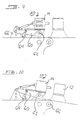
- FIG. 1 schematically shows two components 40 and 50 of a hydraulic excavator, which are connected to one another at two points of engagement 42 and 44.
- a hydraulic quick coupling 10 is arranged on the components 40 and 50.
- the hydraulic lines 46 are shown for simplicity's sake only on the component 50 and extend in a similar manner on the component 40.
- a quick coupling part 12 is fixed, for example, welded or screwed.
- the quick coupling part has on the one hand laterally guide pin 24.
- Centrally coupling sleeves 30 are available. These coupling sleeves are in a manner not shown with corresponding hydraulic lines extending on the component 40, connected.
- a movable quick coupling part 14 is arranged on the component 50.
- the quick coupling part 14 is guided longitudinally displaceably on a linear guide 18 via a support frame 20 in which it is mounted.
- the linear displacement is effected via a piston-cylinder arrangement 16.
- the displaceable quick-coupling part 14 can thus be moved in the direction of arrow a onto the stationary quick-coupling part 12 via the piston-cylinder arrangement 16, so that the guide pins 24 retract into centering bores 26 provided correspondingly in the movable quick-coupling part 14.
- the two quick coupling parts are properly aligned against each other, so that corresponding coupling connector 32, which are arranged on the movable quick coupling part, can retract into the corresponding coupling sleeves 30 on the fixed quick coupling part 12.
- the movable quick coupling part 14 is shown in the retracted position, in which the piston-cylinder assembly 16 is retracted.
- the hydraulic quick coupling 10 is shown in plan view according to FIG. In contrast, in Figure 4, the hydraulic quick coupling is shown in engaged state. This means that the movable quick coupling part 14 has been moved via the piston-cylinder assembly 16 in the direction of the fixed quick coupling part 12, so that the guide pin 24 retract into the corresponding centering holes 34.
- the hydraulic quick coupling 10 is fixed via a locking bolt 28.
- the locking bolt 28 is hydraulically movable in the manner shown here and passes through a corresponding through-hole through the guide pin 24 (see Figure 4).
- the movable quick coupling part 14 is mounted on springs 22 in the support frame 20.
- a guide means 34 is additionally shown in the form of a guide pin, which engages in the retracted position of the quick coupling part 14 in the centering holes 26.
- the movable quick coupling part is also fixed in its retracted position, as shown in Figures 1, 2 and 3, so that corresponding forces and moments acting through the hydraulic lines 46 on the spring-mounted quick coupling part 14 are compensated.
- FIG. 9 A modification of the hydraulic quick coupling 10 according to the invention results from the figures 9 and 10.
- the movable quick coupling part 14 is slidably mounted on a lab rack 60.
- the bearing block 60 is pivotable about a corresponding axis 62 by means of a piston-cylinder arrangement 64.
- the bearing block 60 can also be bolted in the end position with a stop plate 66 which is arranged on the component 50.
- a stop plate 66 which is arranged on the component 50.
- a correspondingly bent component is shown in FIG.
- the component on which the fixed quick coupling part 12 sits bent by a certain angle by which the movable quick coupling part by means of the bearing block 60 is also pivoted.
Landscapes
- Engineering & Computer Science (AREA)
- Mechanical Engineering (AREA)
- Mining & Mineral Resources (AREA)
- Civil Engineering (AREA)
- General Engineering & Computer Science (AREA)
- Structural Engineering (AREA)
- Transportation (AREA)
- Quick-Acting Or Multi-Walled Pipe Joints (AREA)
- Conveying And Assembling Of Building Elements In Situ (AREA)
- Fluid-Pressure Circuits (AREA)
- Transplanting Machines (AREA)
Abstract
Description
- Die Erfindung betrifft eine Hydraulikschnellkupplung nach dem Oberbegriff des Anspruchs 1.
- Hydraulikschnellkupplungen sind bei Kranen, Umschlaggeräten oder Baumaschinen, wie beispielsweise Baggern zum Kuppeln von Bauteilen, die für einen bestimmten Einsatz oder für den Transport getrennt oder umgerüstet werden müssen, weithin verbreitet.
- Dabei erfolgt die mechanische Verbindung der Bauteile meist durch Schnellwechselsysteme, wobei das Kuppeln der Energieübertragungsleitungen vor allem bei größeren Querschnitten mit erheblichem Kraft- und Zeitaufwand verbunden ist.
- Aufgabe der Erfindung ist es, eine Hydraulikschnellkupplung zu schaffen, die einerseits den Kraft- und Zeitaufwand reduziert und die andererseits durch Verwendung leckölfreier Einzelkupplungen die Verschmutzung des Hydrauliköls vermindert.
- Erfindungsgemäß wird die Aufgabe durch die Kombination der Merkmale des Anspruchs 1 gelöst.
- Demnach werden bei einer Hydraulikschnellkupplung nach dem Oberbegriff des Anspruchs 1 zwei miteinander zusammenwirkende Schnellkupplungsteile vorgesehen, die jeweils auf den miteinander zu verbindenden bzw. zu trennenden Bauteilen angeordnet sind. Ein Schnellkupplungsteil weist zumindest einen Führungsbolzen auf, der in eine Zentrierbohrung des gegenüberliegenden Schnellkupplungsteils eingreifen kann, wobei in jedem Schnellkupplungsteil Kupplungsstecker bzw. Kupplungsmuffen zur Verbindung der Hydraulikleitungen vorgesehen sind und wobei zumindest ein Schnellkupplungsteil beweglich auf einem Bauteil angeordnet ist, um die beiden Schnellkupplungsteile zu verbinden bzw. zu trennen.
- Bevorzugte Ausgestaltungen der Erfindung ergeben sich aus den sich an den Hauptanspruch anschließenden Unteransprüchen. Demnach kann bevorzugt ein Schnellkupplungsteil fest auf einem Bauteil angeordnet sein, während das andere Schnellkupplungsteil beweglich auf dem zweiten Bauteil angeordnet ist.
- Besonders vorteilhaft ist zumindest eines der Schnellkupplungsteile federnd in einem Tragrahmen gelagert. Hierdurch kann die Kupplung von auf die Bauteile wirkenden Kräften freigehalten werden. Das im Tragrahmen federnd gelagerte Schnellkupplungsteil kann zusammen mit dem Tragrahmen beweglich auf dem Bauteil gelagert sein.
- Es kann mindestens eine Verriegelung vorhanden sein, über die die Schnellkupplungsteile im gekuppelten Zustand miteinander verriegelbar sind. Dabei kann die Verriegelung den mindestens einen in die entsprechende mindestens eine Zentrierbohrung eingefahrenen Führungsbolzen festlegen.
- Das bewegliche Schnellkupplungsteil kann verschieblich auf einer Linearführung sitzen. Wie zuvor ausgeführt, kann auch der Tragrahmen, in dem das Schnellkupplungsteil federnd gelagert ist auf dieser Linearführung geführt sein. Vorteilhaft ist das bewegliche Schnellkupplungsteil über eine Kolben-Zylinderanordnung verschiebbar. Zur Verriegelung der Schnellkupplungsteile im eingekoppelten Zustand kann beispielsweise auch durch eine permanente Druckbelastung der Kolben-Zylinderanordnung bzw. durch entsprechende Sperrventile die gekuppelte Stellung der beiden Schnellkupplungsteile fixiert werden.
- Vorzugsweise kann das bewegliche und im Tragrahmen federnd gelagerte Schnellkupplungsteil in seiner geöffneten Stellung mittels eines Führungsmittels fixiert sein. Das Führungsmittel kann beispielsweise aus einem Führungsbolzen bestehen, der in die Kupplungsmuffe in geöffneter Stellung des Schnellkupplungsteils eingreift. In dieser Stellung wird durch das Führungsmittel, also beispielsweise einen Führungsbolzen eine Führung des federnd gelagerten Schnellkupplungsteils ermöglicht, sodass die auf diesen wirkenden Schlauchkräfte aufgenommen werden können. Beim Einkuppeln des Schnellkupplungsteils, das heißt beim Bewegen in die geschlossene Stellung, fährt das Schnellkupplungsteil mit seiner Zentrierbohrung auf den Führungsbolzen des anderen gegenüberliegenden Schnellkupplungsteils. In der gekuppelten Position gibt das Führungsmittel, also beispielsweise der Führungsbolzen, die entsprechende Kupplungsmuffe frei. Die entsprechende Festlegung des Schnellkupplungsteils wird durch den Führungsbolzen des gegenüberliegenden Schnellkupplungsteils übernommen.
- Um eine Möglichkeit zu schaffen, auch beim Abknicken der Bauteile um ihren Einbolzpunkt noch kuppeln zu können, wird mindestens eines der beiden Schnellkupplungsteile auf einem verschwenkbaren Lagerblock angeordnet. Der Lagerbock kann mittels einer eigenen Kolben-Zylinderanordnung verschwenkbar sein. Das auf dem Lagerbock angeordnete Schnellkupplungsteil kann darüber hinaus auf dem Lagerbock längs verfahrbar sein und mit einer anderen Kolben-Zylinderanordnung entlang der Längsführung hin und her bewegt werden. Hierdurch ist das Kuppeln der Schnellkupplungsteile auch in abgeknickter Position möglich.
- Weitere Merkmale, Einzelheiten und Vorteile der Erfindung werden anhand von in den Figuren dargestellten Ausführungsbeispielen näher erläutert. Es zeigen:
- Fig. 1:
- eine perspektivische Ansicht einer ersten Ausführungsvariante einer Hydraulikschnellkupplung,
- Fig. 2:
- eine Seitenansicht, teilweise geschnitten, der Anordnung gemäß Figur 1 in einer ersten Position,
- Fig. 3:
- eine Darstellung gemäß Figur 2 aus der Sicht von oben,
- Fig. 4:
- ein Schnitt entsprechend der Schnittlinie IV - IV in Figur 3,
- Fig. 5:
- ein Schnitt entsprechend der Schnittlinie V - V gemäß Figur 3,
- Fig. 6:
- eine Ansicht von vorne auf das bewegliche Schnellkupplungsteil entsprechend einer Ausführungsform gemäß der Figuren 1 bis 5,
- die Fig. 7, 8:
- andere federnde Aufhängungen für das bewegliche Schnellkupplungsteil und
- die Fig. 9 und 10:
- eine modifizierte Hydraulikschnellkupplung gemäß der vorliegenden Erfindung in zwei unterschiedlichen Positionen.
- In der Figur 1 sind schematisch zwei Bauteile 40 und 50 eines Hydraulikbaggers gezeigt, die an zwei Einbolzpunkten 42 und 44 miteinander verbunden sind. Auf den Bauteilen 40 und 50 ist eine Hydraulikschnellkupplung 10 angeordnet. Über die Hydraulikschnellkupplung 10 werden auf den jeweiligen Bauteilen 40 und 50 verlaufende Hydraulikleitungen 46 miteinander verbunden. Die Hydraulikleitungen 46 sind aus Vereinfachungsgründen nur auf dem Bauteil 50 gezeigt und verlaufen in ähnlicher Weise auf dem Bauteil 40. Auf dem Bauteil 40 ist ein Schnellkupplungsteil 12 fest angeordnet, beispielsweise verschweißt bzw. verschraubt. Das Schnellkupplungsteil weist einerseits seitlich Führungsbolzen 24 auf. Mittig sind Kupplungsmuffen 30 vorhanden. Diese Kupplungsmuffen sind in nicht dargestellter Art und Weise mit entsprechenden Hydraulikleitungen, die auf dem Bauteil 40 verlaufen, verbunden. Auf dem Bauteil 50 ist ein beweglicher Schnellkupplungsteil 14 angeordnet. In der hier dargestellten Ausführungsvariante ist das Schnellkupplungsteil 14 über einen Tragrahmen 20, in welchem dieses gelagert ist, längsverschieblich auf einer Linearführung 18 geführt. Die Linearverschiebung erfolgt über eine Kolben-Zylinderanordnung 16. Über die Kolben-Zylinderanordnung 16 kann also der verschiebliche Schnellkupplungsteil 14 in Pfeilrichtung a auf den feststehenden Schnellkupplungsteil 12 hinbewegt werden, sodass die Führungsbolzen 24 in entsprechend in dem beweglichen Schnellkupplungsteil 14 vorgesehene Zentrierbohrungen 26 einfahren. Hierdurch werden die beiden Schnellkupplungsteile richtig gegeneinander ausgerichtet, sodass entsprechende Kupplungsstecker 32, die am beweglichen Schnellkupplungsteil angeordnet sind, in die entsprechenden Kupplungsmuffen 30 am feststehenden Schnellkupplungsteil 12 einfahren können.
- Diese Situation ist insbesondere in den Figuren 2 bis 4 dargestellt. In Figur 2 ist das bewegliche Schnellkupplungsteil 14 in zurückgezogener Position gezeigt, in welcher die Kolben-Zylinderanordnung 16 eingezogen ist.
- In gleicher Position ist die Hydraulikschnellkupplung 10 in der Draufsicht gemäß Figur 3 gezeigt. Dagegen ist in der Figur 4 die Hydraulikschnellkupplung in eingekuppeltem Zustand gezeigt. Das bedeutet, dass das bewegliche Schnellkupplungsteil 14 über die Kolben-Zylinderanordnung 16 in Richtung zum feststehenden Schnellkupplungsteil 12 bewegt wurde, sodass die Führungsbolzen 24 in die entsprechenden Zentrierbohrungen 34 einfahren. In der entsprechend gekuppelten Stellung wird die Hydraulikschnellkupplung 10 über einen Verriegelungsbolzen 28 festgelegt. Der Verriegelungsbolzen 28 ist in hier dargestellter Art und Weise hydraulisch bewegbar und tritt durch ein entsprechendes Durchsteckloch durch den Führungsbolzen 24 hindurch (vgl. Figur 4).
- Das bewegliche Schnellkupplungsteil 14 ist über Federn 22 im Tragrahmen 20 gelagert. Einen entsprechenden Schnitt durch die federnde Lagerung zeigt die Figur 5. Hierdurch wird sichergestellt, dass die Schnellkupplungsteile beim Kuppeln ohne Verkantungen miteinander verbunden werden können.
- In den Figuren 1 bis 4 ist zusätzlich ein Führungsmittel 34 in Form eines Führungsbolzens gezeigt, der in zurückgezogener Stellung des Schnellkupplungsteils 14 in die Zentrierbohrungen 26 eingreift. Hierdurch wird das bewegliche Schnellkupplungsteil auch in seiner zurückgezogenen Stellung, wie sie in den Figuren 1, 2 und 3 gezeigt ist festgelegt, sodass entsprechende Kräfte und Momente, die durch die Hydraulikleitungen 46 auf das federnd gelagerte Schnellkupplungsteil 14 einwirken, ausgeglichen werden.
- In den Figuren 6, 7 und 8 sind unterschiedliche federnde Aufhängungen des beweglichen Schnellkupplungsteils 14 im Tragrahmen 20 gezeigt. Wie den Figuren im einzelnen zu entnehmen ist, sind die Tragrahmen 20 hier unterschiedlich ausgebildet und die Federn 22 in unterschiedlicher Art und Weise angeordnet. Hier sind natürlich nur Ausführungsbeispiele dargestellt, die beliebig im Rahmen der Erfindung varüert werden können.
- Eine Modifikation der erfindungsgemäßen Hydraulikschnellkupplung 10 ergibt sich aus den Figuren 9 bzw. 10. Hier ist das bewegliche Schnellkupplungsteil 14 auf einem Laberbock 60 verschieblich angeordnet. Der Lagerbock 60 ist um eine entsprechende Achse 62 mittels einer Kolben-Zylinderanordnung 64 verschwenkbar. Zur Sicherung kann der Lagerbock 60 auch noch mit einem Anschlagblech 66, das auf dem Bauteil 50 angeordnet ist, in der Endposition verbolzt werden. Wie im Vergleich der Figuren 9 und 10 zu sehen ist, kann aufgrund dieser Ausgestaltung der Hydraulikschnellkupplung 10 auch ein abgeknicktes Bauteil angekoppelt werden. Ein entsprechend abgeknicktes Bauteil ist in der Figur 10 gezeigt. Hier ist um den Einbolzpunkt 66 das Bauteil, auf dem der feste Schnellkupplungsteil 12 sitzt, um einen bestimmten Winkel abgeknickt, um den das bewegliche Schnellkupplungsteil mittels des Lagerbocks 60 ebenfalls geschwenkt wird.
Claims (11)
- Hydraulikschnellkupplung (10) zum Kuppeln von Bauteilen (40, 50) von Kranen, Umschlaggeräten oder Baumaschinen, die beispielsweise für einen bestimmten Einsatz oder für den Transport getrennt oder umgerüstet werden,
gekennzeichnet durch
zwei miteinander zusammenwirkende Schnellkupplungsteile (12, 14), die jeweils auf den Bauteilen (40, 50) angeordnet sind, wobei ein Schnellkupplungsteil (40) zumindest einen Führungsbolzen (24) aufweist, der in eine Zentrierbohrung (26) des gegenüberliegenden Schnellkupplungsteils (14) eingreifen kann, wobei in jedem Schnellkupplungsteil (12, 14) Kupplungsstecker (32) bzw. Kupplungsmuffen (30) zur Verbindung der Hydraulikleitungen vorgesehen sind und wobei zumindest ein Schnellkupplungsteil (14) beweglich auf einem Bauteil (50) angeordnet ist, um die beiden Schnellkupplungsteile (12, 14) zu verbinden bzw. zu trennen. - Hydraulikschnellkupplung nach dem vorhergehenden Anspruch, dadurch gekennzeichnet, dass ein Schnellkupplungsteil (12) fest auf einem Bauteil (40) angeordnet ist und dass das andere Schnellkupplungsteil (14) beweglich auf dem zweiten Bauteil (50) angeordnet ist.
- Hydraulikschnellkupplung nach einem der vorhergehenden Ansprüche, dadurch gekennzeichnet, dass zumindest eines der Schnellkupplungsteile (14) federnd in einem Tragrahmen (20) gelagert ist.
- Hydraulikschnellkupplung nach dem vorhergehenden Anspruch, dadurch gekennzeichnet, dass der Tragrahmen (20) beweglich auf dem Bauteil (50) gelagert ist.
- Hydraulikschnellkupplung nach einem der vorhergehenden Ansprüche, dadurch gekennzeichnet, dass mindestens eine Verriegelung (28) vorhanden ist, die die Schnellkupplungsteile (12, 14) im gekuppelten Zustand miteinander verriegelt.
- Hydraulikschnellkupplung nach Anspruch 5, dadurch gekennzeichnet, dass die Verriegelung (28) den mindestens einen in die entsprechende mindestens eine Zentrierbohrung (30) eingefahrenen Führungsbolzen (28) festlegt.
- Hydraulikschnellkupplung nach einem der vorhergehenden Ansprüche, dadurch gekennzeichnet, dass das bewegliche Schnellkupplungsteil (14) verschieblich auf einer Linearführung (18) sitzt.
- Hydraulikschnellkupplung nach Anspruch 7, dadurch gekennzeichnet, dass das bewegliche Schnellkupplungsteil (14) über eine Kolben-Zylinderanordnung (16) verschiebbar ist.
- Hydraulikschnellkupplung nach einem der vorhergehenden Ansprüche, dadurch gekennzeichnet, dass das bewegliche und im Tragrahmen (20) federnd gelagerte Schnellkupplungsteil (14) in seiner geöffneten Stellung mittels einem Führungsmittel (34) fixiert ist.
- Hydraulikschnellkupplung nach einem der vorhergehenden Ansprüche, dadurch gekennzeichnet, dass mindestens eines der beiden Schnellkupplungsteile (14) auf einem verschwenkbaren Lagerbock (60) angeordnet ist.
- Hydraulikschnellkupplung nach dem vorhergehenden Anspruch, dadurch gekennzeichnet, dass der Lagerbock mittels einer Kolben-Zylinderanordnung verschwenkbar ist.
Applications Claiming Priority (1)
| Application Number | Priority Date | Filing Date | Title |
|---|---|---|---|
| DE102004037459A DE102004037459A1 (de) | 2004-08-02 | 2004-08-02 | Hydraulikschnellkupplung |
Publications (3)
| Publication Number | Publication Date |
|---|---|
| EP1624116A2 true EP1624116A2 (de) | 2006-02-08 |
| EP1624116A3 EP1624116A3 (de) | 2006-04-19 |
| EP1624116B1 EP1624116B1 (de) | 2009-05-06 |
Family
ID=35266972
Family Applications (1)
| Application Number | Title | Priority Date | Filing Date |
|---|---|---|---|
| EP05016588A Active EP1624116B1 (de) | 2004-08-02 | 2005-07-29 | Hydraulikschnellkupplung |
Country Status (5)
| Country | Link |
|---|---|
| US (1) | US7464967B2 (de) |
| EP (1) | EP1624116B1 (de) |
| AT (1) | ATE430843T1 (de) |
| DE (2) | DE102004037459A1 (de) |
| ES (1) | ES2323272T3 (de) |
Cited By (10)
| Publication number | Priority date | Publication date | Assignee | Title |
|---|---|---|---|---|
| EP2112008A1 (de) * | 2008-04-23 | 2009-10-28 | Jost-Werke GmbH | Steckerkonsole für ein Anhängerfahrzeug eines Lastzuges |
| WO2009112553A3 (de) * | 2008-03-12 | 2009-11-05 | Jost-Werke Gmbh | Steckersysteme für anhängerfahrzeug |
| EP2389792A1 (de) * | 2010-05-28 | 2011-11-30 | RAD Technologies | Positionsjustierbare Kupplung und damit ausgerüstete Fahrzeugkupplung |
| WO2013041583A1 (de) * | 2011-09-20 | 2013-03-28 | Invite GmbH | Haltegestell für eine multikupplung zum befüllen und/oder entleeren eines chemieanlagencontainers |
| AT513587A1 (de) * | 2012-10-15 | 2014-05-15 | Perwein Baumaschinen Systeme Gmbh | Vorrichtung zur Verbindung von Leitungen |
| AT16092U1 (de) * | 2017-07-27 | 2019-01-15 | Lasco Heutechnik Gmbh | Fahrzeug mit einer Hydraulikpumpe |
| EP3434828A1 (de) * | 2017-07-28 | 2019-01-30 | Komatsu Europe International N.V. | Arbeitsausrüstung für ein arbeitsfahrzeug und arbeitsfahrzeug |
| WO2019081831A1 (fr) * | 2017-10-26 | 2019-05-02 | Groupe Mecalac | Dispositif de connexion automatique entre un outil et un porte-outil d'engin de chantier ou de travaux publics |
| EP3517690A1 (de) * | 2018-01-25 | 2019-07-31 | OilQuick Deutschland GmbH | Adapter, schnellwechsler und schnellwechselsystem |
| EP3680393A1 (de) * | 2019-01-08 | 2020-07-15 | Hiltec Designs Ltd | Koppler mit netzanschlusssystem |
Families Citing this family (35)
| Publication number | Priority date | Publication date | Assignee | Title |
|---|---|---|---|---|
| AT9279U1 (de) * | 2006-03-23 | 2007-07-15 | Wimmer Alois Ing | Werkzeugerkennung |
| SE530621C2 (sv) * | 2006-12-01 | 2008-07-22 | Nordhydraulic Ab | Hydraulisk anslutning |
| SE530620C2 (sv) * | 2006-12-01 | 2008-07-22 | Nordhydraulic Ab | Parkeringsorgan för hydraulisk koppling |
| US20080271425A1 (en) * | 2007-05-01 | 2008-11-06 | Ricketts Jonathan E | Apparatus and method for automatically coupling of electrical and hyraulic systems of a header of an agricultural harvesting machine |
| US20090121476A1 (en) * | 2007-11-08 | 2009-05-14 | The Government Of The Us, As Represented By The Secretary Of The Navy | Microfluidic Bus for Interconnecting Multiple Fluid Conduits |
| AT506554B1 (de) * | 2008-03-20 | 2011-11-15 | Alois Ing Wimmer | Kupplungsvorrichtung mit einer einrichtung zum automatischen verbinden von energieleitungen |
| FR2933155B1 (fr) * | 2008-06-30 | 2010-08-27 | Staubli Sa Ets | Ensemble de connexion et procede de connexion d'un tel ensemble |
| KR101049864B1 (ko) * | 2008-12-03 | 2011-07-19 | 동재공업주식회사 | 유, 공압 호스이음용 커플러의 다중 이음장치 |
| EP2330331B1 (de) | 2009-12-04 | 2018-09-26 | Caterpillar Work Tools B. V. | Kopplungsvorrichtung für Verbinderkomponenten |
| EP2426267B1 (de) * | 2010-09-07 | 2020-12-30 | Caterpillar Work Tools B. V. | Kupplungsanordnung |
| JP5403013B2 (ja) * | 2011-08-24 | 2014-01-29 | コベルコ建機株式会社 | 作業機械における配管取付け構造 |
| US8955864B2 (en) * | 2011-09-30 | 2015-02-17 | Agco Corporation | Docking station |
| EP2787128A4 (de) * | 2011-11-30 | 2016-02-24 | Volvo Constr Equip Ab | Hydraulikleitungsbefestigungsvorrichtung bagger mit schwenkbarem ausleger |
| PL2630983T3 (pl) * | 2012-02-22 | 2017-04-28 | Erbe Elektromedizin Gmbh | Złącze płynowe z wieloma promieniowo ruchomymi elementami wtykowymi |
| US20150275466A1 (en) | 2013-07-16 | 2015-10-01 | Clark Equipment Company | Implement interface |
| EP3052706B1 (de) | 2013-07-16 | 2019-08-07 | Clark Equipment Company | Geräteschnittstelle |
| EP2902582B2 (de) | 2014-01-29 | 2022-12-28 | BAUER Maschinen GmbH | Mastanordnung und Verfahren zum Verbinden einer Werkzeugeinheit mit einem Mastschlitten einer Mastanordnung |
| SE539425C2 (sv) | 2014-09-03 | 2017-09-19 | Ytf Sweden Ab | Snabbkoppling för fastkoppling av ett hydraulmanövrerat verktyg/redskap på en grävmaskin |
| CA2995334C (en) * | 2015-09-14 | 2018-09-04 | Thomas Bruckner | Breaker device for acting onto a closure element of a medical tubing |
| US9968021B2 (en) * | 2016-01-19 | 2018-05-15 | Deere & Company | Work vehicle multi-coupler with breakaway feature |
| WO2018074937A1 (en) * | 2016-10-21 | 2018-04-26 | Doherty Engineered Attachments Limited | A coupling assembly and an attachment member comprising a coupling member |
| US10995477B2 (en) * | 2017-03-01 | 2021-05-04 | William Lewis | Coupler guard system |
| US10676324B2 (en) | 2017-03-05 | 2020-06-09 | Thomas A Weeks | Plug and play tool connection |
| US10806066B2 (en) | 2018-05-18 | 2020-10-20 | Deere & Company | Implement multi-coupler with breakaway feature |
| US11255070B2 (en) | 2018-06-15 | 2022-02-22 | Clark Equipment Company | Hydraulic coupling |
| DE102018120470B4 (de) * | 2018-08-22 | 2021-04-01 | Saf-Holland Gmbh | Verbindungssystem und Verbindungseinheit |
| US11319808B2 (en) * | 2018-10-12 | 2022-05-03 | Caterpillar Global Mining Equipment Llc | Hose retention system for drilling machine |
| DE102019202352A1 (de) * | 2019-02-21 | 2020-08-27 | Jost-Werke Deutschland Gmbh | Verbindungseinrichtung, Verbindungssystem sowie Sattelzug |
| US11453993B2 (en) | 2019-06-17 | 2022-09-27 | Caterpillar Inc. | Quick coupler with hydraulic coupling manifold |
| US11053660B2 (en) * | 2019-06-17 | 2021-07-06 | Caterpillar Inc. | Coupling assembly and method of hydraulically coupling to a tool |
| US11560188B2 (en) * | 2019-07-12 | 2023-01-24 | Isee, Inc. | Automatic tractor trailer coupling |
| IT201900020246A1 (it) * | 2019-11-04 | 2021-05-04 | Comau Spa | "Sistema di docking per il collegamento idraulico fra un'unità operativa e una o più unità mobili di servizio, con dispositivo di supporto flottante" |
| DE102020006487A1 (de) | 2020-10-20 | 2022-04-21 | Dürr Somac GmbH | Schnellwechseleinrichtung für einen Fülladapter |
| US20230030953A1 (en) * | 2021-08-02 | 2023-02-02 | Cnh Industrial America Llc | Quick storage cradle for combine multicoupler |
| DE102022126522A1 (de) | 2022-10-12 | 2024-04-18 | Liebherr-France Sas | Arbeitsmaschine mit Kupplungsvorrichtung für fluidführende Leitungen |
Citations (2)
| Publication number | Priority date | Publication date | Assignee | Title |
|---|---|---|---|---|
| US4738463A (en) | 1987-02-24 | 1988-04-19 | Deere & Company | Automatically coupling fluid connector for a hitch |
| DE10159417A1 (de) | 2001-03-09 | 2002-09-26 | Liebherr Hydraulikbagger | Schnellkupplung |
Family Cites Families (14)
| Publication number | Priority date | Publication date | Assignee | Title |
|---|---|---|---|---|
| US2334875A (en) | 1941-09-29 | 1943-11-23 | Thompson Prod Inc | Multiple detachable coupling |
| CA1259088A (en) | 1985-05-10 | 1989-09-05 | Raoul Fremy | Automatically-operated self-sealing zero-spillage fluid coupling device |
| FR2656258A1 (fr) * | 1989-12-22 | 1991-06-28 | Pommier & Cie | Attelage automatique pour vehicule routier. |
| SE468320C (sv) * | 1991-02-26 | 1998-01-26 | Chrial Engineering Handelsbola | Hydrauliskt kopplingsarrangemang |
| SE467742B (sv) * | 1991-09-06 | 1992-09-07 | Sonerud John Teodor | Anordning foer snabbkoppling av ett redskap till en graevmaskin med samtidig anslutning till ett drivsystem |
| FR2687115B1 (fr) * | 1992-02-07 | 1998-05-22 | Emily Sa Ets | Systeme d'accouplement et de desaccouplement a un vehicule d'un accessoire disposant d'organes a commande hydraulique ou pneumatique. |
| SE504450C2 (sv) * | 1996-02-19 | 1997-02-17 | Kavlugnt Ab | Kopplingsanordning för sammankoppling av ett arbetsredskap till en arbetsmaskin; både mekanisk hopkoppling och snabbkoppling av hydraullikkopplingarna |
| US5829337A (en) * | 1997-08-28 | 1998-11-03 | Caterpillar Inc. | Method and apparatus for coupling a fluid-powered implement to a work machine |
| DE19751292C1 (de) * | 1997-11-19 | 1999-02-18 | Robert Riedlberger | Vorrichtung zum Schutz von Verbindungselementen an Baugeräten vor Schmutz und Spritzwasser |
| FR2813941B1 (fr) * | 2000-09-08 | 2003-05-16 | Mailleux Sa | Systeme d'accouplement mecanique et multifluidique d'un outil sur un cadre porte-outil |
| PL200100B1 (pl) | 2001-03-09 | 2008-12-31 | Liebherr Hydraulikbagger | Szybkozłącze |
| AT411839B (de) * | 2001-09-28 | 2004-06-25 | Puehringer Josef Ing Mag | Frontlader |
| DE10200836A1 (de) * | 2002-01-08 | 2003-07-24 | Thomas Sauer | Schnellwechselvorrichtung für Arbeitsmaschinen |
| AT412976B (de) * | 2002-05-23 | 2005-09-26 | Hauer Franz | Einrichtung zur kupplung der an einem tragfahrzeug und einer diesem zugeordneten ladeeinrichtung angeordneten kupplungselemente für das hydraulische betätigungssystem |
-
2004
- 2004-08-02 DE DE102004037459A patent/DE102004037459A1/de not_active Ceased
-
2005
- 2005-07-29 ES ES05016588T patent/ES2323272T3/es active Active
- 2005-07-29 DE DE502005007227T patent/DE502005007227D1/de active Active
- 2005-07-29 EP EP05016588A patent/EP1624116B1/de active Active
- 2005-07-29 AT AT05016588T patent/ATE430843T1/de active
- 2005-08-01 US US11/195,331 patent/US7464967B2/en active Active
Patent Citations (2)
| Publication number | Priority date | Publication date | Assignee | Title |
|---|---|---|---|---|
| US4738463A (en) | 1987-02-24 | 1988-04-19 | Deere & Company | Automatically coupling fluid connector for a hitch |
| DE10159417A1 (de) | 2001-03-09 | 2002-09-26 | Liebherr Hydraulikbagger | Schnellkupplung |
Cited By (20)
| Publication number | Priority date | Publication date | Assignee | Title |
|---|---|---|---|---|
| WO2009112553A3 (de) * | 2008-03-12 | 2009-11-05 | Jost-Werke Gmbh | Steckersysteme für anhängerfahrzeug |
| US8187020B2 (en) | 2008-03-12 | 2012-05-29 | Jost-Werke Gmbh | Plug-in system for trailer vehicles |
| EP2112008A1 (de) * | 2008-04-23 | 2009-10-28 | Jost-Werke GmbH | Steckerkonsole für ein Anhängerfahrzeug eines Lastzuges |
| EP2389792A1 (de) * | 2010-05-28 | 2011-11-30 | RAD Technologies | Positionsjustierbare Kupplung und damit ausgerüstete Fahrzeugkupplung |
| US10308499B2 (en) | 2011-09-20 | 2019-06-04 | Bayer Aktiengesellschaft | Retaining frame for a multicoupling for filling and/or draining a chemical plant container |
| WO2013041583A1 (de) * | 2011-09-20 | 2013-03-28 | Invite GmbH | Haltegestell für eine multikupplung zum befüllen und/oder entleeren eines chemieanlagencontainers |
| US10899601B2 (en) | 2011-09-20 | 2021-01-26 | Bayer Aktiengesellschaft | Retaining frame for a multicoupling for filling and/or draining a chemical plant container |
| AT513587A1 (de) * | 2012-10-15 | 2014-05-15 | Perwein Baumaschinen Systeme Gmbh | Vorrichtung zur Verbindung von Leitungen |
| AT16092U1 (de) * | 2017-07-27 | 2019-01-15 | Lasco Heutechnik Gmbh | Fahrzeug mit einer Hydraulikpumpe |
| EP3434828A1 (de) * | 2017-07-28 | 2019-01-30 | Komatsu Europe International N.V. | Arbeitsausrüstung für ein arbeitsfahrzeug und arbeitsfahrzeug |
| WO2019081831A1 (fr) * | 2017-10-26 | 2019-05-02 | Groupe Mecalac | Dispositif de connexion automatique entre un outil et un porte-outil d'engin de chantier ou de travaux publics |
| FR3072981A1 (fr) * | 2017-10-26 | 2019-05-03 | Groupe Mecalac | Dispositif de connexion automatique entre un outil et un porte-outil d'engin de chantier ou de travaux publics |
| CN111279033A (zh) * | 2017-10-26 | 2020-06-12 | 麦克拉克集团 | 用于建筑或公共工程机械的工具与工具架之间自动连接的装置 |
| JP2021509702A (ja) * | 2017-10-26 | 2021-04-01 | グループ・メカラック | 建設または公共工事機械の工具と工具ホルダとの間の自動接続のための装置 |
| CN111279033B (zh) * | 2017-10-26 | 2022-04-08 | 麦克拉克集团 | 用于建筑或公共工程机械的工具与工具架之间自动连接的装置 |
| US11560688B2 (en) | 2017-10-26 | 2023-01-24 | Groupe Mecalac | Device for automatic connection between a tool and a tool holder of a construction or public works machine |
| AU2018356833B2 (en) * | 2017-10-26 | 2024-03-21 | Groupe Mecalac | Device for automatic connection between a tool and a tool holder of a construction or public works machine |
| EP3517690A1 (de) * | 2018-01-25 | 2019-07-31 | OilQuick Deutschland GmbH | Adapter, schnellwechsler und schnellwechselsystem |
| EP3680393A1 (de) * | 2019-01-08 | 2020-07-15 | Hiltec Designs Ltd | Koppler mit netzanschlusssystem |
| US11332908B2 (en) | 2019-01-08 | 2022-05-17 | Hiltec Designs Ltd | Coupler with power connection system |
Also Published As
| Publication number | Publication date |
|---|---|
| ATE430843T1 (de) | 2009-05-15 |
| ES2323272T3 (es) | 2009-07-10 |
| DE102004037459A1 (de) | 2006-02-23 |
| US20060022455A1 (en) | 2006-02-02 |
| DE502005007227D1 (de) | 2009-06-18 |
| EP1624116B1 (de) | 2009-05-06 |
| US7464967B2 (en) | 2008-12-16 |
| EP1624116A3 (de) | 2006-04-19 |
Similar Documents
| Publication | Publication Date | Title |
|---|---|---|
| EP1624116B1 (de) | Hydraulikschnellkupplung | |
| DE102006023420B4 (de) | Schnellwechselvorrichtung | |
| DE69717080T2 (de) | Einrichtung zum verbinden eines hydraulischen werkzeuges mit einer arbeitsmaschine | |
| DE4214569C2 (de) | Schnellwechselvorrichtung | |
| DE102005037105C5 (de) | Adapter für ein Arbeitsgerät als Teil einer Schnellwechselvorrichtung und Schnellwechselvorrichtung | |
| EP1727946B1 (de) | Schnellwechselvorrichtung mit einer hydraulischen kupplung für medien an einem baugerät | |
| EP3591122B1 (de) | Schnellwechsler | |
| DE202019101747U1 (de) | Schnellwechsler für Baumaschinenwerkzeuge | |
| EP2902582B1 (de) | Mastanordnung und Verfahren zum Verbinden einer Werkzeugeinheit mit einem Mastschlitten einer Mastanordnung | |
| DE2640840C2 (de) | ||
| DE29810118U1 (de) | Arbeitsmaschine | |
| DE102009060097A1 (de) | Abdeckungsvorrichtung | |
| EP1388616A1 (de) | Vorrichtung zum Kuppeln und Entkuppeln der Anschlussenden von Druckmittelleitungen | |
| EP3901378A1 (de) | Schnellkupplung mit zentriervorrichtung | |
| DE102019125861A1 (de) | Schnellwechsler | |
| DE29702648U1 (de) | Vorrichtung zur Ver- und Entriegelung eines Werkzeugs an einem Werkzeug-Aufnahmerahmen von Kompaktladern | |
| EP1458938B1 (de) | Frontlader mit einer automatischen kupplungsvorrichtung | |
| DE4408386C2 (de) | Hydraulisch betätigte Verriegelungsvorrichtung für Schnellwechsler an Bau- und Arbeitsmaschinen | |
| EP3517690A1 (de) | Adapter, schnellwechsler und schnellwechselsystem | |
| DE102009046213B4 (de) | Wechselrahmen für einen Frontlader | |
| DE202008011190U1 (de) | Scharnier und Werkzeug zur Demontage eines Lineardämpfers von einem Scharnier | |
| DE69811737T2 (de) | Förderkette, anordnung und verfahren zum verbinden der glieder | |
| DE4111522C2 (de) | Wechselsystem für Werkzeuge an Bediengeräten | |
| EP4159928B1 (de) | Schnellwechsler | |
| DE69700246T2 (de) | Montageverfahren für einen Kupplungsring in einem Waschmaschinenbehälter |
Legal Events
| Date | Code | Title | Description |
|---|---|---|---|
| PUAI | Public reference made under article 153(3) epc to a published international application that has entered the european phase |
Free format text: ORIGINAL CODE: 0009012 |
|
| AK | Designated contracting states |
Kind code of ref document: A2 Designated state(s): AT BE BG CH CY CZ DE DK EE ES FI FR GB GR HU IE IS IT LI LT LU LV MC NL PL PT RO SE SI SK TR |
|
| AX | Request for extension of the european patent |
Extension state: AL BA HR MK YU |
|
| PUAL | Search report despatched |
Free format text: ORIGINAL CODE: 0009013 |
|
| RTI1 | Title (correction) |
Free format text: HYDRAULIC QUICK COUPLER |
|
| AK | Designated contracting states |
Kind code of ref document: A3 Designated state(s): AT BE BG CH CY CZ DE DK EE ES FI FR GB GR HU IE IS IT LI LT LU LV MC NL PL PT RO SE SI SK TR |
|
| AX | Request for extension of the european patent |
Extension state: AL BA HR MK YU |
|
| RTI1 | Title (correction) |
Free format text: HYDRAULIC QUICK COUPLER |
|
| 17P | Request for examination filed |
Effective date: 20060518 |
|
| 17Q | First examination report despatched |
Effective date: 20060622 |
|
| AKX | Designation fees paid |
Designated state(s): AT BE BG CH CY CZ DE DK EE ES FI FR GB GR HU IE IS IT LI LT LU LV MC NL PL PT RO SE SI SK TR |
|
| GRAP | Despatch of communication of intention to grant a patent |
Free format text: ORIGINAL CODE: EPIDOSNIGR1 |
|
| GRAS | Grant fee paid |
Free format text: ORIGINAL CODE: EPIDOSNIGR3 |
|
| GRAA | (expected) grant |
Free format text: ORIGINAL CODE: 0009210 |
|
| AK | Designated contracting states |
Kind code of ref document: B1 Designated state(s): AT BE BG CH CY CZ DE DK EE ES FI FR GB GR HU IE IS IT LI LT LU LV MC NL PL PT RO SE SI SK TR |
|
| REG | Reference to a national code |
Ref country code: GB Ref legal event code: FG4D Free format text: NOT ENGLISH |
|
| REG | Reference to a national code |
Ref country code: CH Ref legal event code: NV Representative=s name: BOVARD AG PATENTANWAELTE Ref country code: CH Ref legal event code: EP |
|
| REG | Reference to a national code |
Ref country code: IE Ref legal event code: FG4D |
|
| REF | Corresponds to: |
Ref document number: 502005007227 Country of ref document: DE Date of ref document: 20090618 Kind code of ref document: P |
|
| REG | Reference to a national code |
Ref country code: ES Ref legal event code: FG2A Ref document number: 2323272 Country of ref document: ES Kind code of ref document: T3 |
|
| REG | Reference to a national code |
Ref country code: SE Ref legal event code: TRGR |
|
| PG25 | Lapsed in a contracting state [announced via postgrant information from national office to epo] |
Ref country code: PT Free format text: LAPSE BECAUSE OF FAILURE TO SUBMIT A TRANSLATION OF THE DESCRIPTION OR TO PAY THE FEE WITHIN THE PRESCRIBED TIME-LIMIT Effective date: 20090906 Ref country code: LT Free format text: LAPSE BECAUSE OF FAILURE TO SUBMIT A TRANSLATION OF THE DESCRIPTION OR TO PAY THE FEE WITHIN THE PRESCRIBED TIME-LIMIT Effective date: 20090506 |
|
| PG25 | Lapsed in a contracting state [announced via postgrant information from national office to epo] |
Ref country code: PL Free format text: LAPSE BECAUSE OF FAILURE TO SUBMIT A TRANSLATION OF THE DESCRIPTION OR TO PAY THE FEE WITHIN THE PRESCRIBED TIME-LIMIT Effective date: 20090506 Ref country code: SI Free format text: LAPSE BECAUSE OF FAILURE TO SUBMIT A TRANSLATION OF THE DESCRIPTION OR TO PAY THE FEE WITHIN THE PRESCRIBED TIME-LIMIT Effective date: 20090506 Ref country code: LV Free format text: LAPSE BECAUSE OF FAILURE TO SUBMIT A TRANSLATION OF THE DESCRIPTION OR TO PAY THE FEE WITHIN THE PRESCRIBED TIME-LIMIT Effective date: 20090506 Ref country code: IS Free format text: LAPSE BECAUSE OF FAILURE TO SUBMIT A TRANSLATION OF THE DESCRIPTION OR TO PAY THE FEE WITHIN THE PRESCRIBED TIME-LIMIT Effective date: 20090906 |
|
| REG | Reference to a national code |
Ref country code: IE Ref legal event code: FD4D |
|
| PG25 | Lapsed in a contracting state [announced via postgrant information from national office to epo] |
Ref country code: DK Free format text: LAPSE BECAUSE OF FAILURE TO SUBMIT A TRANSLATION OF THE DESCRIPTION OR TO PAY THE FEE WITHIN THE PRESCRIBED TIME-LIMIT Effective date: 20090506 Ref country code: RO Free format text: LAPSE BECAUSE OF FAILURE TO SUBMIT A TRANSLATION OF THE DESCRIPTION OR TO PAY THE FEE WITHIN THE PRESCRIBED TIME-LIMIT Effective date: 20090506 Ref country code: IE Free format text: LAPSE BECAUSE OF FAILURE TO SUBMIT A TRANSLATION OF THE DESCRIPTION OR TO PAY THE FEE WITHIN THE PRESCRIBED TIME-LIMIT Effective date: 20090506 Ref country code: CZ Free format text: LAPSE BECAUSE OF FAILURE TO SUBMIT A TRANSLATION OF THE DESCRIPTION OR TO PAY THE FEE WITHIN THE PRESCRIBED TIME-LIMIT Effective date: 20090506 Ref country code: EE Free format text: LAPSE BECAUSE OF FAILURE TO SUBMIT A TRANSLATION OF THE DESCRIPTION OR TO PAY THE FEE WITHIN THE PRESCRIBED TIME-LIMIT Effective date: 20090506 |
|
| BERE | Be: lapsed |
Owner name: LIEBHERR-HYDRAULIKBAGGER G.M.B.H. Effective date: 20090731 |
|
| PLBI | Opposition filed |
Free format text: ORIGINAL CODE: 0009260 |
|
| PG25 | Lapsed in a contracting state [announced via postgrant information from national office to epo] |
Ref country code: SK Free format text: LAPSE BECAUSE OF FAILURE TO SUBMIT A TRANSLATION OF THE DESCRIPTION OR TO PAY THE FEE WITHIN THE PRESCRIBED TIME-LIMIT Effective date: 20090506 Ref country code: MC Free format text: LAPSE BECAUSE OF NON-PAYMENT OF DUE FEES Effective date: 20090731 |
|
| PLAX | Notice of opposition and request to file observation + time limit sent |
Free format text: ORIGINAL CODE: EPIDOSNOBS2 |
|
| 26 | Opposition filed |
Opponent name: BAUER MASCHINEN GMBH Effective date: 20100205 |
|
| PG25 | Lapsed in a contracting state [announced via postgrant information from national office to epo] |
Ref country code: BG Free format text: LAPSE BECAUSE OF FAILURE TO SUBMIT A TRANSLATION OF THE DESCRIPTION OR TO PAY THE FEE WITHIN THE PRESCRIBED TIME-LIMIT Effective date: 20090806 |
|
| PG25 | Lapsed in a contracting state [announced via postgrant information from national office to epo] |
Ref country code: BE Free format text: LAPSE BECAUSE OF NON-PAYMENT OF DUE FEES Effective date: 20090731 |
|
| PLBB | Reply of patent proprietor to notice(s) of opposition received |
Free format text: ORIGINAL CODE: EPIDOSNOBS3 |
|
| PG25 | Lapsed in a contracting state [announced via postgrant information from national office to epo] |
Ref country code: GR Free format text: LAPSE BECAUSE OF FAILURE TO SUBMIT A TRANSLATION OF THE DESCRIPTION OR TO PAY THE FEE WITHIN THE PRESCRIBED TIME-LIMIT Effective date: 20090807 |
|
| REG | Reference to a national code |
Ref country code: CH Ref legal event code: PFA Owner name: LIEBHERR-HYDRAULIKBAGGER GMBH Free format text: LIEBHERR-HYDRAULIKBAGGER GMBH#LIEBHERRSTRASSE 12#88457 KIRCHDORF/ILLER (DE) -TRANSFER TO- LIEBHERR-HYDRAULIKBAGGER GMBH#LIEBHERRSTRASSE 12#88457 KIRCHDORF/ILLER (DE) |
|
| PG25 | Lapsed in a contracting state [announced via postgrant information from national office to epo] |
Ref country code: LU Free format text: LAPSE BECAUSE OF NON-PAYMENT OF DUE FEES Effective date: 20090729 |
|
| PG25 | Lapsed in a contracting state [announced via postgrant information from national office to epo] |
Ref country code: HU Free format text: LAPSE BECAUSE OF FAILURE TO SUBMIT A TRANSLATION OF THE DESCRIPTION OR TO PAY THE FEE WITHIN THE PRESCRIBED TIME-LIMIT Effective date: 20091107 |
|
| PG25 | Lapsed in a contracting state [announced via postgrant information from national office to epo] |
Ref country code: TR Free format text: LAPSE BECAUSE OF FAILURE TO SUBMIT A TRANSLATION OF THE DESCRIPTION OR TO PAY THE FEE WITHIN THE PRESCRIBED TIME-LIMIT Effective date: 20090506 |
|
| PG25 | Lapsed in a contracting state [announced via postgrant information from national office to epo] |
Ref country code: CY Free format text: LAPSE BECAUSE OF FAILURE TO SUBMIT A TRANSLATION OF THE DESCRIPTION OR TO PAY THE FEE WITHIN THE PRESCRIBED TIME-LIMIT Effective date: 20090506 |
|
| PLCK | Communication despatched that opposition was rejected |
Free format text: ORIGINAL CODE: EPIDOSNREJ1 |
|
| PLBN | Opposition rejected |
Free format text: ORIGINAL CODE: 0009273 |
|
| STAA | Information on the status of an ep patent application or granted ep patent |
Free format text: STATUS: OPPOSITION REJECTED |
|
| 27O | Opposition rejected |
Effective date: 20111215 |
|
| REG | Reference to a national code |
Ref country code: DE Ref legal event code: R100 Ref document number: 502005007227 Country of ref document: DE Effective date: 20111215 |
|
| REG | Reference to a national code |
Ref country code: FR Ref legal event code: PLFP Year of fee payment: 12 |
|
| REG | Reference to a national code |
Ref country code: FR Ref legal event code: PLFP Year of fee payment: 13 |
|
| REG | Reference to a national code |
Ref country code: FR Ref legal event code: PLFP Year of fee payment: 14 |
|
| P01 | Opt-out of the competence of the unified patent court (upc) registered |
Effective date: 20230607 |
|
| PGFP | Annual fee paid to national office [announced via postgrant information from national office to epo] |
Ref country code: NL Payment date: 20230724 Year of fee payment: 19 |
|
| PGFP | Annual fee paid to national office [announced via postgrant information from national office to epo] |
Ref country code: IT Payment date: 20230727 Year of fee payment: 19 Ref country code: GB Payment date: 20230720 Year of fee payment: 19 Ref country code: FI Payment date: 20230721 Year of fee payment: 19 Ref country code: ES Payment date: 20230801 Year of fee payment: 19 Ref country code: CH Payment date: 20230802 Year of fee payment: 19 Ref country code: AT Payment date: 20230719 Year of fee payment: 19 |
|
| PGFP | Annual fee paid to national office [announced via postgrant information from national office to epo] |
Ref country code: SE Payment date: 20230721 Year of fee payment: 19 Ref country code: FR Payment date: 20230721 Year of fee payment: 19 |
|
| PGFP | Annual fee paid to national office [announced via postgrant information from national office to epo] |
Ref country code: DE Payment date: 20240724 Year of fee payment: 20 |