EP1623875A1 - Appareil de surveillance et procédé d'affichage d'image à vue d'oiseau - Google Patents
Appareil de surveillance et procédé d'affichage d'image à vue d'oiseau Download PDFInfo
- Publication number
- EP1623875A1 EP1623875A1 EP05250848A EP05250848A EP1623875A1 EP 1623875 A1 EP1623875 A1 EP 1623875A1 EP 05250848 A EP05250848 A EP 05250848A EP 05250848 A EP05250848 A EP 05250848A EP 1623875 A1 EP1623875 A1 EP 1623875A1
- Authority
- EP
- European Patent Office
- Prior art keywords
- image
- eye
- bird
- fish
- eye view
- Prior art date
- Legal status (The legal status is an assumption and is not a legal conclusion. Google has not performed a legal analysis and makes no representation as to the accuracy of the status listed.)
- Ceased
Links
- 240000004050 Pentaglottis sempervirens Species 0.000 title claims abstract description 167
- 235000004522 Pentaglottis sempervirens Nutrition 0.000 title claims abstract description 167
- 238000012544 monitoring process Methods 0.000 title claims abstract description 43
- 238000000034 method Methods 0.000 title claims description 40
- 238000006243 chemical reaction Methods 0.000 claims abstract description 38
- 238000003786 synthesis reaction Methods 0.000 claims description 21
- 230000015654 memory Effects 0.000 claims description 18
- 230000006870 function Effects 0.000 claims description 15
- 238000003384 imaging method Methods 0.000 claims description 3
- 238000010586 diagram Methods 0.000 description 12
- 238000013507 mapping Methods 0.000 description 10
- 230000015572 biosynthetic process Effects 0.000 description 7
- 239000011159 matrix material Substances 0.000 description 7
- 239000002131 composite material Substances 0.000 description 6
- 238000001514 detection method Methods 0.000 description 6
- 239000003550 marker Substances 0.000 description 5
- 239000007787 solid Substances 0.000 description 3
- 230000005540 biological transmission Effects 0.000 description 1
- 238000000354 decomposition reaction Methods 0.000 description 1
- 238000009472 formulation Methods 0.000 description 1
- 239000000203 mixture Substances 0.000 description 1
- 230000036544 posture Effects 0.000 description 1
- 230000003068 static effect Effects 0.000 description 1
Images


Classifications
-
- B—PERFORMING OPERATIONS; TRANSPORTING
- B60—VEHICLES IN GENERAL
- B60R—VEHICLES, VEHICLE FITTINGS, OR VEHICLE PARTS, NOT OTHERWISE PROVIDED FOR
- B60R1/00—Optical viewing arrangements; Real-time viewing arrangements for drivers or passengers using optical image capturing systems, e.g. cameras or video systems specially adapted for use in or on vehicles
- B60R1/20—Real-time viewing arrangements for drivers or passengers using optical image capturing systems, e.g. cameras or video systems specially adapted for use in or on vehicles
- B60R1/22—Real-time viewing arrangements for drivers or passengers using optical image capturing systems, e.g. cameras or video systems specially adapted for use in or on vehicles for viewing an area outside the vehicle, e.g. the exterior of the vehicle
- B60R1/23—Real-time viewing arrangements for drivers or passengers using optical image capturing systems, e.g. cameras or video systems specially adapted for use in or on vehicles for viewing an area outside the vehicle, e.g. the exterior of the vehicle with a predetermined field of view
- B60R1/27—Real-time viewing arrangements for drivers or passengers using optical image capturing systems, e.g. cameras or video systems specially adapted for use in or on vehicles for viewing an area outside the vehicle, e.g. the exterior of the vehicle with a predetermined field of view providing all-round vision, e.g. using omnidirectional cameras
-
- G—PHYSICS
- G06—COMPUTING; CALCULATING OR COUNTING
- G06T—IMAGE DATA PROCESSING OR GENERATION, IN GENERAL
- G06T3/00—Geometric image transformations in the plane of the image
- G06T3/04—Context-preserving transformations, e.g. by using an importance map
- G06T3/047—Fisheye or wide-angle transformations
-
- G—PHYSICS
- G06—COMPUTING; CALCULATING OR COUNTING
- G06T—IMAGE DATA PROCESSING OR GENERATION, IN GENERAL
- G06T5/00—Image enhancement or restoration
- G06T5/80—Geometric correction
-
- B—PERFORMING OPERATIONS; TRANSPORTING
- B60—VEHICLES IN GENERAL
- B60R—VEHICLES, VEHICLE FITTINGS, OR VEHICLE PARTS, NOT OTHERWISE PROVIDED FOR
- B60R1/00—Optical viewing arrangements; Real-time viewing arrangements for drivers or passengers using optical image capturing systems, e.g. cameras or video systems specially adapted for use in or on vehicles
- B60R1/12—Mirror assemblies combined with other articles, e.g. clocks
- B60R2001/1253—Mirror assemblies combined with other articles, e.g. clocks with cameras, video cameras or video screens
-
- B—PERFORMING OPERATIONS; TRANSPORTING
- B60—VEHICLES IN GENERAL
- B60R—VEHICLES, VEHICLE FITTINGS, OR VEHICLE PARTS, NOT OTHERWISE PROVIDED FOR
- B60R2300/00—Details of viewing arrangements using cameras and displays, specially adapted for use in a vehicle
- B60R2300/10—Details of viewing arrangements using cameras and displays, specially adapted for use in a vehicle characterised by the type of camera system used
- B60R2300/105—Details of viewing arrangements using cameras and displays, specially adapted for use in a vehicle characterised by the type of camera system used using multiple cameras
-
- B—PERFORMING OPERATIONS; TRANSPORTING
- B60—VEHICLES IN GENERAL
- B60R—VEHICLES, VEHICLE FITTINGS, OR VEHICLE PARTS, NOT OTHERWISE PROVIDED FOR
- B60R2300/00—Details of viewing arrangements using cameras and displays, specially adapted for use in a vehicle
- B60R2300/20—Details of viewing arrangements using cameras and displays, specially adapted for use in a vehicle characterised by the type of display used
- B60R2300/207—Details of viewing arrangements using cameras and displays, specially adapted for use in a vehicle characterised by the type of display used using multi-purpose displays, e.g. camera image and navigation or video on same display
-
- B—PERFORMING OPERATIONS; TRANSPORTING
- B60—VEHICLES IN GENERAL
- B60R—VEHICLES, VEHICLE FITTINGS, OR VEHICLE PARTS, NOT OTHERWISE PROVIDED FOR
- B60R2300/00—Details of viewing arrangements using cameras and displays, specially adapted for use in a vehicle
- B60R2300/30—Details of viewing arrangements using cameras and displays, specially adapted for use in a vehicle characterised by the type of image processing
- B60R2300/302—Details of viewing arrangements using cameras and displays, specially adapted for use in a vehicle characterised by the type of image processing combining image information with GPS information or vehicle data, e.g. vehicle speed, gyro, steering angle data
-
- B—PERFORMING OPERATIONS; TRANSPORTING
- B60—VEHICLES IN GENERAL
- B60R—VEHICLES, VEHICLE FITTINGS, OR VEHICLE PARTS, NOT OTHERWISE PROVIDED FOR
- B60R2300/00—Details of viewing arrangements using cameras and displays, specially adapted for use in a vehicle
- B60R2300/40—Details of viewing arrangements using cameras and displays, specially adapted for use in a vehicle characterised by the details of the power supply or the coupling to vehicle components
- B60R2300/402—Image calibration
-
- B—PERFORMING OPERATIONS; TRANSPORTING
- B60—VEHICLES IN GENERAL
- B60R—VEHICLES, VEHICLE FITTINGS, OR VEHICLE PARTS, NOT OTHERWISE PROVIDED FOR
- B60R2300/00—Details of viewing arrangements using cameras and displays, specially adapted for use in a vehicle
- B60R2300/60—Details of viewing arrangements using cameras and displays, specially adapted for use in a vehicle characterised by monitoring and displaying vehicle exterior scenes from a transformed perspective
- B60R2300/607—Details of viewing arrangements using cameras and displays, specially adapted for use in a vehicle characterised by monitoring and displaying vehicle exterior scenes from a transformed perspective from a bird's eye viewpoint
-
- B—PERFORMING OPERATIONS; TRANSPORTING
- B60—VEHICLES IN GENERAL
- B60R—VEHICLES, VEHICLE FITTINGS, OR VEHICLE PARTS, NOT OTHERWISE PROVIDED FOR
- B60R2300/00—Details of viewing arrangements using cameras and displays, specially adapted for use in a vehicle
- B60R2300/80—Details of viewing arrangements using cameras and displays, specially adapted for use in a vehicle characterised by the intended use of the viewing arrangement
- B60R2300/802—Details of viewing arrangements using cameras and displays, specially adapted for use in a vehicle characterised by the intended use of the viewing arrangement for monitoring and displaying vehicle exterior blind spot views
-
- B—PERFORMING OPERATIONS; TRANSPORTING
- B60—VEHICLES IN GENERAL
- B60R—VEHICLES, VEHICLE FITTINGS, OR VEHICLE PARTS, NOT OTHERWISE PROVIDED FOR
- B60R2300/00—Details of viewing arrangements using cameras and displays, specially adapted for use in a vehicle
- B60R2300/80—Details of viewing arrangements using cameras and displays, specially adapted for use in a vehicle characterised by the intended use of the viewing arrangement
- B60R2300/8093—Details of viewing arrangements using cameras and displays, specially adapted for use in a vehicle characterised by the intended use of the viewing arrangement for obstacle warning
Definitions
- the present invention relates to a monitoring technique around a moving body such as a vehicle, etc., around which fish-eye cameras mounted on the moving body monitor. More particularly, the present invention relates to a monitoring apparatus around a moving body and a method of displaying a bird's-eye view image, for obtaining a bird's-eye view image based on the images picked up by fish-eye cameras in order to ensure safe driving for the driver.
- a monitoring apparatus used for a moving body has been using an image processing technique for generating a composite image based on the images picked up by a plurality of cameras in order to support safe driving at the time of driving the moving body.
- a plurality of cameras 3 are attached to arbitrary positions of a moving body 2.
- the monitoring apparatus 1 generates a composite image based on the images obtained by the plurality of cameras 3 attached to the arbitrary positions to display the composite image in the vehicle 2, thereby making it possible to contribute to safe driving of the vehicle 2.
- the composite image is produced by image processing such that a hypothetical view point P is set above the vehicle 2 in advance and the vehicle 2 is looked down upon from this hypothetical view point P.
- the image captured from the hypothetical view point P is a wide-angle image including part of the periphery of the vehicle 2, it is possible for the driver of the vehicle 2 to safely drive while viewing the wide-angle image.
- the monitoring apparatus 1 since an ordinary camera having a standard lens is used for each camera 3, the image areas covered by these cameras are relatively small. In order to cover the areas necessary for the driving of the moving body, a large number of cameras must be installed. In this case, it is necessary to perform the composite processing of many images, and thus the image processing becomes complicated and it becomes necessary to take much processing time.
- mapping table must be created in advance, and thus it is necessary to take much work and time for creating that table.
- a blind-spot camera 13 is installed at the blind-spot position of the driver in a vehicle 12.
- a camera using a fish-eye lens hereinafter, referred to as fish-eye camera 14 is installed in a backward direction at the central position of the rear trunk of the vehicle 12.
- the fish-eye image of the backward area of the moving body obtained from the fish-eye camera 14 is dewarping processed into a usual two-dimensional image to provide the driver with a usual image of the blind spot of the backward area of the moving body.
- the monitoring apparatus 11 when the vehicle 12 moves forward or backward, an obstacle which exists in front of or at the back of the vehicle, or a body such as another vehicle, etc., which comes into the backward area becomes visible in a visible area, and thus making it possible to contribute to safer driving.
- the present invention has been made in view of the circumstances described above. It is an object of the present invention to provide a monitoring apparatus and a method of displaying bird's-eye view images, which picks up images around a vehicle, etc., with a few fish-eye cameras to obtain a wide-angle image, and which can convert the fish-eye images into bird's-eye view images at a high speed.
- a monitoring apparatus including: at least one of fish-eye camera mounted on a moving body, to image a fish-eye image around the moving body; a dewarping unit configured to convert at least part of the fish-eye image obtained by the fish-eye camera into a two-dimensional image using a dewarping parameter; a conversion parameter calculation unit configured to calculate a conversion parameter for obtaining a bird's-eye view image from the two-dimensional image, showing an image from a hypothetical position looking down on the moving body; a bird's-eye view image creation unit configured to create a bird's-eye view image by sequentially fetching position data corresponding to each pixel of the bird's-eye view image using the conversion parameter and the dewarping conversion parameter; and a display device to display the bird's-eye view image created by the image creation unit.
- a surveillance apparatus including: a plurality of fish-eye cameras mounted on a vehicle imaging fish-eye images around the vehicle; a dewarping unit configured to dewarp at least parts of the fish-eye images into two-dimensional images using dewarping parameters; a conversion parameter calculation unit configured to calculate conversion parameters for converting the two-dimensional images into bird's-eye view images, each viewing from a hypothetical position looking down on the vehicle; a bird's-eye view image generating unit configured to generate bird's-eye view images by sequentially calculating position data of a pixel in the fish-eye image corresponding to each pixel of the bird's-eye view image using the conversion parameter obtained by the conversion parameter calculation unit and the dewarping parameter; an image superposing unit configured to superpose the bird's-eye view images into an superposed image; and a display device to display the superposed image generated by the image superposing unit.
- a method of displaying a bird's-eye view image including steps of: storing a fish-eye image into a first memory showing surroundings of a movable body obtained using a fish-eye camera attached to the movable body; performing calibration processing on part of the fish-eye image in advance and obtaining a group of image-conversion parameters to be used for converting the fish-eye image into a bird's-eye view image for overlooking the movable body to store the parameters into a second memory; and sequentially calculating an image-data position of the fish-eye image corresponding to each pixel data of the bird's-eye view image using the group of image-conversion parameters of the second memory and sequentially fetching the image data from the first memory as pixel data of the bird's-eye view image to supply to a display device.
- a method of converting an image for converting a fish-eye image obtained by a fish-eye camera mounted on a moving body into a bird's-eye view image viewed from a hypothetically overlooking position of the moving body including: obtaining a dewarping parameter for converting the fish-eye image into a dewarped image and a conversion parameter for converting the dewarped image into the bird's-eye view, thereby storing parameters into a parameter file; and calculating a pixel position in the fish-eye image corresponding to each pixel in the bird's-eye view image using the dewarping parameter and the converting view parameter stored in the parameter file and sequentially fetching the pixel data as pixel data in the bird's-eye view image.
- the present invention it is possible to create a bird's-eye view by setting a hypothetical view point above a vehicle, etc., based on the images picked up including blind-spot areas around a vehicle, etc., using fish-eye cameras installed at predetermined positions of a moving body such as a vehicle, etc.
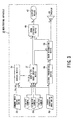
- Figs. 1 to 3 are schematic diagrams illustrating a monitoring apparatus 30 according to embodiments of the present invention.
- the monitoring apparatus 30 is used for monitoring around moving body such as a vehicle 31 or the like.
- respective fish-eye cameras 36 having a function stored an image data (hereinafter, referred to as image data storing function), are mounted on both side-view mirrors 35 of the vehicle 31 such as a private car, etc., and thus a wide-angle image obtained by fish-eye cameras 36 (hereinafter, referred to as fish-eye image) having effective fields of view ⁇ 1 and ⁇ 2 including fields of view that are blind spots from a driver during the driving of the vehicle 31 and upon starting to drive.
- fish-eye image a wide-angle image obtained by fish-eye cameras 36 having effective fields of view ⁇ 1 and ⁇ 2 including fields of view that are blind spots from a driver during the driving of the vehicle 31 and upon starting to drive.
- a concept of the monitoring apparatus 30 is obtaining a bird's-eye view image by setting a hypothetical view point P above the vehicle 31, using fish-eye images obtained by the fish-eye cameras 36, and looking down upon the vehicle 31 and its surroundings from this hypothetical view point P.
- the monitoring apparatus 30 includes a bird's-eye view image creation device 37 described below so as to generate the bird's-eye view image viewed from a hypothetical view point P on the basis of fish-eye images obtained by a plurality of (n) fish-eye cameras 36 installed on the vehicle 31.
- the obtained bird's-eye view is displayed, for example, on a display device 42 such as a navigation display device provided for a car-navigation device and an arbitrary display device through an image-synthesis device 40 described below. Note that the method of creating the bird's-eye view image will be described later.
- the monitoring apparatus 30 also includes a command-input device 32 for allowing the driver to operate and a sensor-information input device 33 for receiving sensor information of various sensors 44a, 44b ..., and 44n (which are shown in Fig.4) provided on the periphery of the vehicle 31.
- the command-input device 32 Upon inputting an operation by user, the command-input device 32 generates input signals (Sa1 and Sa2) and provides the input signals to control device 34.
- the sensor-information input device 33 receives detection signals as sensor information of a solid body which is existent in the vicinity of the outside of the vehicle and of various vehicle information such as the states of the vehicle 31 (a gear position, a steering angle, a vehicle speed or the like), from sensors 44a, 44b ..., and 44n.
- the detection signals of the solid body are obtained from an active sensing device such as a radar used an extremely-high frequency wave (EHF) or the like, which is an example of sensors 44a, 44b ..., and 44n.
- the sensor-information input device 33 provides the detection signals as a sensor-input signal Sb to control device 34 and signal-processing device 38.
- the signal-processing device 38 receives the sensor-input signal Sb. If there is, for example, a solid body around the vehicle acting as an obstacle hindering the travelling of the vehicle, the signal-processing device 38 generates an obstacle-identifying data signal Sc2 to supply it to an image-recognition device 39.
- the image-recognition device 39 recognizes a caution-needed area during driving by an image-recognition method using image-data signals Sd (Sd1 to Sdn) obtained from bird's-eye view image creation device 37. In this case, more preferably, the image-recognition device 39 may also use the obstacle-identifying data signal Sc2. Upon having recognized the caution-needed area, the image-recognition device 39 generates a caution-needed area data signal Se and a voice-guidance signal Sf in order to arouse caution, and outputs the caution-needed area data signal Se and the voice-guidance signal Sf.
- the voice-guidance signal Sf is converted into voice by a speaker 43 installed, for example, at the driver's seat of the vehicle 31 to transmit a voice-guidance from the speaker 43.
- the caution-needed area data signal Se from the image-recognition device 39 is input into the image-synthesis device 40.
- the image-synthesis device 40 receives the caution-needed area data signal Se and a bird's-eye view synthesis image data signal Si output from the bird's-eye view image creation device 37.
- the image-synthesis device 40 generates a synthesis-image data signal Sg which is a signal for displaying the synthesis-image synthesized so as to inform the caution-needed area in the bird's-eye view image, and outputs the synthesis-image data signal Sg to the display device 42.
- the display device 42 receives the synthesis-image data signal Sg, the synthesis-image on the basis of the synthesis-image data signal Sg is displayed on the display device 42 Thus, the synthesis-image is presented to the driver.
- the command-input device 32 has a switch-input unit 32a and a voice-input unit 32b.
- the switch-input unit 32a can output a switch-input signal Sa1 to the control device 34 by appropriately turning on switches in the event that, for example, the driver of the vehicle 31 instructs to display the state of an arbitrary area.
- the voice-input unit 32b can output a voice-input signal Sa2 to the control device 34 by the vehicle 31 driver's instruction to switch to appropriate screen display, etc., by voice.
- the control device 34 has a voice-analysis unit 45.
- the voice-analysis unit 45 analyzes the content of a voice instruction of the voice-input signal Sa2 and can output a voice-analysis signal Sa21 to the controller 47.
- the sensors 44a, 44b ..., and 44n detect a gear-lever position of the vehicle 31, a steering-wheel rotation angle (steering angle), a vehicle speed, or the like as detection signals and output the detection signals to the sensor-information input device 33.
- the detection signals received from the sensor-information input device 33 are input to a sensor-analysis unit 46 as the sensor-input signal Sb.
- the sensor-analysis unit 46 analyzes the sensor-input signal Sb and generates a sensor-analysis signal Sb1 on the basis of an analysis result. Then, the sensor-analysis signal Sb1 is output from the sensor-analysis unit 46 to the controller 47.
- the controller 47 included in the control device 34 receives the switch-input signal Sa1 output from the command-input device 32, the voice-input signal Sa21 output from the voice-analysis unit 45, and output from the sensor-analysis signal Sb1 sensor-analysis unit 46. Then, the controller 47 supplies, for example, a region-of-interest presentation signal Sc1 indicating the display of the interested region (ROI: Region of Interest) and a bird's-eye view image creation instruction signal Sh to the bird's-eye view image creation device 37.
- ROI Region of Interest
- the bird's-eye view image creation device 37 shown in Fig. 5 is configured to create the bird's-eye view image in accordance with the bird's-eye view image creation instruction signal Sh at online bird's-eye view image creation time.
- the bird's-eye view image creation device 37 is configured to display and enlarge a region-of-interest among bird's-eye view images created in accordance with the region-of-interest presentation signal Sc1.
- the bird's-eye view image creation device 37 creates the bird's-eye view images, thereby generating and outputting the bird's-eye view synthesis image data signal Si and the image-data signal Sd.
- the bird's-eye view image creation device 37 includes a selector 50 for selecting the transmission of the camera-image data signals g1 to gn, a calibration processing unit 51 for performing a calibration processing generating a conversion parameters in order to generate the bird's-eye view image, a parameter file 52 for storing the generated conversion parameters, an online-image creation unit 53 for generating a bird's-eye view image using the camera-image data signals g1 to gn and the parameters in the parameter file 52 ,and a monitor 54 for displaying a progress and result of the calibration processing.
- the monitor 54 may be a line-out (output terminal) so as to display another monitor.
- the bird's-eye view image creation device 37 performs a first procedure for performing calibration processing in a calibration processing unit 51 (calibration processing procedure) and a second procedure for creating a bird's-eye view image in the online-image creation unit 53 at driving time of the vehicle 31 (online-image creation processing procedure).
- camera-image data signals g1, g2, ..., gn obtained from a plurality of fish-eye cameras 36 received by the selector 50.
- the camera-image data signals g1 to gn are transmitted to the calibration processing unit 51 at the time of the first procedure, and are transmitted to the online-image creation unit 53 at the time of the second procedure. Further, the region-of-interest presentation signal Sc1 and the bird's-eye view image creation instruction signal Sh from the control device 34 are received by the online-image creation unit 53.
- the calibration processing unit 51 When the calibration processing unit 51 receives the camera-image data signals g1 to gn in advance of driving the vehicle 31, the calibration processing unit 51 starts the calibration processing as the first procedure. In the calibration processing, user can check and verify a progress and result of the calibration processing with reference to the monitor 54. Note that a detailed description of the first procedure will be given hereinafter.
- the fish-eye images obtained online from bird's-eye view image sections 60a, 60b, ..., and 60n shown in Fig. 6 are finally converted into a bird's-eye view image viewed from a hypothetical view point P shown in Fig. 2 using image-synthesis section 62 serving as image-synthesis unit.
- image-synthesis section 62 serving as image-synthesis unit.
- dewarping parameters for dewarping processing the fish-eye images and bird's-eye view image parameters for converting a dewarped image into a bird's-eye view image are used, respectively.
- the parameters of Expression 1 are known, it is possible to convert an fish-eye image into a dewarped image.
- the dewarping parameters are accordance with image pickup characteristics of the fish-eye cameras 36 can be used.
- the plurality of bird's-eye view images corresponding to the plurality of fish-eye cameras 36 are obtained, these images are integrated into one image to be presented as an integrated bird's-eye view image including the vehicle and the surroundings thereof, thereby appropriately presenting the states around the vehicle.
- a method described in detail for example, in Japanese Patent Application No. 2004-158855 specification by the present inventor can be used. Further, in order to achieve high-speed processing, It is possible to omit the step for actually creating dewarped images themselves.
- the dewarping parameters and the bird's-eye view image parameters for using in the online image-creation processing procedure are obtained.
- the dewarping parameters and the bird's-eye view image parameters obtained in the calibration processing are stored in the parameter file 52.
- the calibration processing procedure includes three steps (step 1 to step 3).
- the dewarping parameters related to Expression 1 are obtained for each fish-eye camera 36.
- the bird's-eye view image parameters (H matrix) related to Expression 2 are obtained for each fish-eye camera 36.
- alignment information for performing alignment calibration is obtained in order to integrate a plurality of bird's-eye view images.
- the dewarping parameters necessary for converting fish-eye images obtained from fish-eye cameras 36 into normal two-dimensional images are calculated. That is to say, image-pickup system parameters are calculated on the basis of the CMOS (or CCD) characteristics and lens characteristics of individual fish-eye cameras 36.
- the image-pickup system parameters include information responding to the size of image, the central position of the fish-eye image and the radius of the fish-eye image, at least.
- the parameters are directly related to Expression 1, and are used for coordinate conversions.
- the polar coordinates of one pixel in the fish-eye image area Gx is assumed to be ( ⁇ s, ⁇ s), and the XY coordinates thereof are represented by (x_pixel, Y_pixel). Further, One pixel in the dewarped image area Gy is represented by (Px, Py, Pz).
- the parameters ku and kv are determined by the size of an image and the zoom magnification of a camera. Further, r_pxl is a radius of a fish-eye image.
- the dewarping parameters can be calculated using known information of fish-eye cameras 36 such as the CMOS (or CCD) characteristics, lens characteristics, or the like, in advance.
- an H matrix related to Expression 2 is calculated.
- the step 2 has two sub-steps in order to calculate the H matrix.
- the reason why the step 2 includes two sub-steps resides in that the bird's-eye view image parameters, which are coefficients, etc., of the H matrix, cannot be calculated only by known information such as the attachment positions of the fish-eye cameras 36.
- the fish-eye cameras 36 takes images of a marker Q3 placed on the ground G3, shaped of known four points or more. Then, the shape connecting the corner points of the picked-up image to be viewed from above is drawn and displayed on the monitor 54. Then, the corresponding relationships with the corner points are made by Graphical User Interface (hereinafter, referred to as GUI).
- GUI Graphical User Interface
- a marker Q1 on a dewarped image plane G1 is a dewarped image produced by the dewarping of the fish-eye image obtained by taking the images of the marker Q3 by the fish-eye camera.
- the bird's-eye view image obtained when the dewarped image including the marker Q1 is converted into a bird's-eye view image corresponds to a marker Q2 on a bird's-eye view image plane G2. That is to say, here, the corresponding relationship is established between a pixel (Ui, Vi) in the bird's-eye view image and a pixel (Ui', Vi') in the dewarped image. Accordingly, Expression 3 holds for each suffix i.
- the calibration processing unit 51 of the bird's-eye view image creation device 37 obtains the image dewarping processed on the basis of the attachment position of the fish-eye camera 36 from the fish-eye image area Gx, which is part of the fish-eye images. In this case, it is desirable to pick up the image of a figure having a known shape by the fish-eye camera 36.
- the dewarping processing be performed on the fish-eye image (portion including a known figure) of the fish-eye image area Gx for a known fish-eye image.
- the dewarping processed image is displayed on the monitor 54, and a plurality of (four or more) points (pixel positions) of the known figure are specified using GUI. For example, in the event that the points of the known figure are four points on a square on the ground G3, the bird's-eye view of the square should be obtained.
- the known figure on the ground G3 used in this processing is not limited to a square. As long as a known figure, the corresponding relation between the two figures can be specified.
- step 3 for calibrating the alignment of a bird's-eye view image alignment information for integrating into one bird's-eye view image is obtained by aligning the positions Q3' on the screen corresponding to markers y11 to y14 imaged in a plurality of image-pickup areas 65a to 65d. More particularly, in the event that the bird's-eye view images obtained from individual image-pickup areas are displayed on the monitor 54, the user specifies the corresponding markers by using GUI. Thus, it is possible to obtain alignment information indicating positional relationships of individual bird's-eye view images.
- the dewarping parameters, the bird's-eye view image parameters, and the alignment information obtained by the calibration processing described above are stored in the parameter file 52 and are used for generating an online image.
- the online-image creation unit 53 as a dewarping unit, a conversion parameter calculation unit, and a bird's-eye view image creation unit includes: the bird's-eye view image sections 60a to 60n for generating bird's-eye view images based on the camera-image data signals g1, g2, ..., gn obtained from a plurality of fish-eye cameras 36 using the dewarping conversion parameters and the H matrix conversion parameters; and the image-synthesis section 62 for receiving the image-data signals Sd (Sd1 to Sdn) processed and generated by the bird's-eye view image sections 60a to 60n to generate the bird's-eye view synthesis image data signal Si.
- the bird's-eye view image sections 60a to 60n generate the image-data signals Sd corresponding to bird's-eye view images by using the parameters contained in the parameter file 52 shown in Fig. 5 when The bird's-eye view image sections 60a to 60n receives the camera-image data signals g1, g2, .., gn obtained from a plurality of fish-eye cameras 36, respectively. Since various parameters are known by the calibration processing procedure, the corresponding positions between the pixels in the bird's-eye view images and the pixels in the dewarped images can be calculated by using Expression 2. Further, by the relation of Expression 1, it is possible to calculate the pixels in the dewarped images and the texel values (the values of original pixels to be texture mapped) in the original fish-eye images.
- the pixel position in the fish-eye image corresponding to an arbitrary pixel in the bird's-eye view image is calculated, and the image data of the pixel position is fetched in sequence, thereby creating a bird's-eye view image.
- the bird's-eye view images are directly created from the fish-eye images.
- the image-synthesis section 62 performs synthesis processing to integrate the image data included in the image-data signals Sd1 to Sdn generated by the bird's-eye view image sections 60a to 60n into one image data.
- the image-synthesis section 62 generates the bird's-eye view synthesis image data signal Si including an image produced, by the image processing, into one bird's-eye view image using the alignment information obtained in advance.
- the bird's-eye view image sections 60a to 60n perform the bird's-eye view image processing by using Expression 1 and Expression 2.
- the image-synthesis section 62 has a function of processing the overlapped areas in the process of integrating the image-data signals Sd directly into one image signal as necessary. That is to say, not only one image out of the overlapped area images is drawn, but a plurality of image-data signals Sd drawing the same area are appropriately blended in order to draw one image.
- a plurality of image-data signals Sd drawing the same area are appropriately blended in order to draw one image.
- one bird's-eye view image in which the feet of the images (persons) x1 and x2 obtained by being imaged from the effective fields of view ⁇ 1 and ⁇ 2 of the fish-eye cameras 36, respectively, and each one being installed at each of the side mirrors 35, are joined at one common point in a duplicated image area 67.
- the images picked up by the fish-eye cameras 36 are integrated, and one bird's-eye view image is displayed on the display device 42 as shown in Fig. 2.
- this image is easy for the driver to view.
- the image is highlighted, it is further easier to be viewed.
- the fish-eye images obtained by the fish-eye cameras 36 are first processed by the bird's-eye view image sections 60a to 60n of the online-image creation unit 53 by selecting and extracting the dewarping parameters corresponding to each fish-eye camera 36, thereby the dewarping images and the bird's-eye view images described above are obtained.
- the image-synthesis section 62 expands only the portion corresponding to the noticed area of one fish-eye image obtained from the fish-eye camera corresponding to one bird's-eye view image section corresponding to the target fish-eye camera using the fish-eye camera number and the noticed area instruction signal which are separately specified from the command-input device 32 as necessary to be supplied to the display device, thereby making it possible to display a bird's-eye view image of the interested portion (direction).
- the image-synthesis device 40 synthesizes the caution-needed area data signal Se as the recognition result of the image-recognition device 39 and the bird's-eye view synthesis image data signal Si as necessary to supply it to the display device 42, for example, the navigation display device.
- the image-recognition device 39 recognizes an obstacle based a moving vector of a body in the bird's-eye view image. Specifically, suppose that when the vehicle 31, which is a moving body, moves, for example, a static body on the ground changes in accordance with the movement of this vehicle 31 in the bird's-eye view scene (image).
- the image-recognition device 39 detects a moving body whether or not there is a constant vector in the bird's-eye view image, thereby making it possible to find this moving body not having the constant vector as a moving obstacle.
- the image-recognition device 39 may issue a warning by a voice guidance or the like.
- the monitoring apparatus 30 of the present invention may adopt GPU (graphics processor unit) so as to generate an online image.
- GPU graphics processor unit
- GPU has a dewarping image processing function for performing the dewarping image processing, and a bird's-eye view image processing function for performing bird's-eye view image processing (GPU function)
- GPU is capable of performing the dewarping image processing and the bird's-eye view image processing at a high speed.
- the calculation of the texture in Expression 2 can be executed, for example, by calculating four corner points of the bird's-eye view image to be displayed by Expression 2 in advance, and then by performing texture mapping the inside of the figure in the homogeneous coordinate mode.
- the monitoring apparatus 30 adopted GPU 82 in the online-image creation unit 53, includes bird's-eye view image sections 80a, 80b, ..., and 80n in stead of the bird's-eye view image sections 60a, 60b, ..., and 60n.
- the bird's-eye view image sections 80a, 80b, ..., and 80n includes an application processing section 81 for performing an application processing (step a1 to step a4), and GPU 82 for performing the dewarping image processing (step b1) and the bird's-eye view image processing (step b2) at high speed. Accordingly, each bird's-eye view image section as shown in Fig. 12 can perform processing at a high speed by the cooperation of application processing section 81 and the GPU 82.
- the application processing section 81 is preinstalled an application software for executing the application processing in which the positions of four corners of the drawing area to be displayed as a bird's-eye view image are calculated.
- the application processing includes the step a1 to the step a4.
- texture coordinates (ui, vi, wi) in the dewarped image corresponding to the four corner points are calculated by using Expression 2.
- the coordinates (ui', vi', wi') of the texture mapping destination of the portion corresponding to the area determined in the step 1 from the step 2 are clearly indicated, and the entire fish-eye original image is clearly shown as a texture.
- the coordinates of the texture mapping destination of the rectangular portion and the coordinates (ui', vi', wi') of the texture are clearly shown.
- the processing corresponding to Expression 1 used in the dewarping processing is executed by the dewarping processing function of GPU 82
- the processing corresponding to Expression 2 used in the bird's-eye view image processing is executed by the bird's-eye view image processing function of GPU 82.
- step b1 three-dimensional nonlinear texture mapping is performed on the fish-eye image 70 of a fish-eye image memory (first memory) 61 by homogeneous coordinates and the generated dewarped image data is stored in a dewarped image memory (second memory) 63 as a dewarped image 71.
- step b2 three-dimensional linear texture mapping is performed on the dewarped image 71 to generate a bird's-eye view image 73.
- steps b1 and b2 for performing each texture mapping the plane including a bird's-eye view image as viewed from the bird's-eye view position is considered as a drawing area, and is considered as the target of the texture mapping performed in three dimensions. Thus, considerable processing can be performed on the graphic board.
- At least one of the steps b1 and b2 for performing each texture mapping is performed by high-speed processing (GPU processing), and thus it is possible to perform color processing and moving-image processing at a high speed in particular.
- GPU processing high-speed processing
- the first memory 61 and the second memory 63 may be virtual memories.
- respective bird's-eye view image sections 80a, 80b, ... , and 80n can perform whether or not the first memory 61 and the second memory 63 are virtual memories. That is to say, since the dewarped images are not created in the middle, it is possible to directly convert a fish-eye image into a bird's-eye view image online at a high speed.
- GPU 82 is not necessarily in respective bird's-eye view image sections 80a, 80b, ..., and 80n. GPU 82 may be shared in the online-image creation unit 53A.
- the online-image creation unit 53A may include at least one of bird's-eye view image sections 80a, 80b, ..., and 80n, and one GPU 82.
- the monitoring apparatus 30 can draw moving images at a high speed, and thus it is possible to apply the apparatus to a video monitor mounted on a vehicle, capable of being used in real time.
- the vehicle 31 exemplified as a moving body of the monitoring apparatus 30 is not necessarily a moving body.
- a body such as a fixed body simply including fish-eye cameras may be used.
- each fish-eye camera 36 of the monitoring apparatus 30 does not always have the image data storing function.
- the monitoring apparatus 30 may include fish-eye cameras 36 not having the image data storing function and an image capture device having the image data storing function, or a bird's-eye image creation device further having the image data storing function, instead of fish-eye cameras 36 having the image data storing function.
Landscapes
- Engineering & Computer Science (AREA)
- Physics & Mathematics (AREA)
- General Physics & Mathematics (AREA)
- Theoretical Computer Science (AREA)
- Multimedia (AREA)
- Mechanical Engineering (AREA)
- Image Processing (AREA)
- Closed-Circuit Television Systems (AREA)
- Image Analysis (AREA)
Applications Claiming Priority (1)
| Application Number | Priority Date | Filing Date | Title |
|---|---|---|---|
| JP2004229945A JP4744823B2 (ja) | 2004-08-05 | 2004-08-05 | 周辺監視装置および俯瞰画像表示方法 |
Publications (1)
| Publication Number | Publication Date |
|---|---|
| EP1623875A1 true EP1623875A1 (fr) | 2006-02-08 |
Family
ID=34940468
Family Applications (1)
| Application Number | Title | Priority Date | Filing Date |
|---|---|---|---|
| EP05250848A Ceased EP1623875A1 (fr) | 2004-08-05 | 2005-02-15 | Appareil de surveillance et procédé d'affichage d'image à vue d'oiseau |
Country Status (4)
| Country | Link |
|---|---|
| US (1) | US7511734B2 (fr) |
| EP (1) | EP1623875A1 (fr) |
| JP (1) | JP4744823B2 (fr) |
| CN (1) | CN100401323C (fr) |
Cited By (9)
| Publication number | Priority date | Publication date | Assignee | Title |
|---|---|---|---|---|
| WO2008044911A1 (fr) * | 2006-10-09 | 2008-04-17 | Tele Atlas B.V. | Procédé et appareil destinés à produire des pavés orthocorrigés |
| DE102009005505A1 (de) | 2008-03-28 | 2009-10-01 | Volkswagen Ag | Verfahren zur Erzeugung eines Abbildes der Umgebung eines Kraftfahrzeugs |
| EP1968011A3 (fr) * | 2007-01-31 | 2011-03-09 | Sanyo Electric Co., Ltd. | Procédé et appareil pour l'étalonnage d'une caméra, et véhicule |
| US7965871B2 (en) | 2006-07-13 | 2011-06-21 | Mitsubishi Fuso Truck And Bus Corporation | Moving-state determining device |
| CN103916572A (zh) * | 2012-12-28 | 2014-07-09 | 财团法人工业技术研究院 | 车用镜头的自动化校正与应用其的影像转换方法与装置 |
| CN104641405A (zh) * | 2012-07-30 | 2015-05-20 | 市光工业株式会社 | 车辆用警报装置和车辆用车外后视镜装置 |
| US20160264227A1 (en) * | 2011-10-31 | 2016-09-15 | Yamaha Hatsudoki Kabushiki Kaisha | Watercraft |
| US10040394B2 (en) | 2015-06-17 | 2018-08-07 | Geo Semiconductor Inc. | Vehicle vision system |
| EP3450920A1 (fr) * | 2010-12-30 | 2019-03-06 | TomTom International B.V. | Procédés et systèmes d'information utilisant un appareil de navigation |
Families Citing this family (53)
| Publication number | Priority date | Publication date | Assignee | Title |
|---|---|---|---|---|
| DE202004014778U1 (de) * | 2004-09-22 | 2006-02-09 | Mekra Lang Gmbh & Co. Kg | Nutzfahrzeuge mit Kameraeinrichtung sowie Kameraeinrichtung hierfür |
| JP4596978B2 (ja) * | 2005-03-09 | 2010-12-15 | 三洋電機株式会社 | 運転支援システム |
| JP4810953B2 (ja) * | 2005-10-07 | 2011-11-09 | 日産自動車株式会社 | 車両用死角映像表示装置 |
| JP4707109B2 (ja) * | 2006-03-02 | 2011-06-22 | アルパイン株式会社 | 複数カメラ撮影画像処理方法及び装置 |
| EP2018066B1 (fr) * | 2006-05-09 | 2019-10-02 | Nissan Motor Co., Ltd. | Dispositif et procédé d'acquisition d'images du périmètre d'un véhicule |
| DE102006036933B4 (de) | 2006-08-08 | 2024-01-11 | Bayerische Motoren Werke Aktiengesellschaft | Verfahren zur Erzeugung eines Gesamtbilds aus überlappenden Einzelbildern |
| JP2008187564A (ja) * | 2007-01-31 | 2008-08-14 | Sanyo Electric Co Ltd | カメラ校正装置及び方法並びに車両 |
| JP4823938B2 (ja) * | 2007-02-14 | 2011-11-24 | アルパイン株式会社 | 画面切り替え判定装置、車両周辺監視装置および画面切り替え判定方法 |
| JP5120880B2 (ja) | 2007-10-15 | 2013-01-16 | アルパイン株式会社 | 画像処理装置及び画像処理方法 |
| JP2009100342A (ja) * | 2007-10-18 | 2009-05-07 | Sanyo Electric Co Ltd | カメラ校正装置及び方法、並びに、車両 |
| CN101842808A (zh) * | 2007-11-16 | 2010-09-22 | 电子地图有限公司 | 用于产生车道信息的方法及设备 |
| JP4902575B2 (ja) * | 2008-02-27 | 2012-03-21 | 日立オートモティブシステムズ株式会社 | 道路標示認識装置、および道路標示認識方法 |
| JP5187179B2 (ja) * | 2008-12-16 | 2013-04-24 | 三菱自動車工業株式会社 | 車両周辺監視装置 |
| JP5068779B2 (ja) * | 2009-02-27 | 2012-11-07 | 現代自動車株式会社 | 車両周囲俯瞰画像表示装置及び方法 |
| JP4751939B2 (ja) * | 2009-03-31 | 2011-08-17 | アイシン精機株式会社 | 車載カメラの校正装置 |
| JP5064601B2 (ja) * | 2009-06-29 | 2012-10-31 | パナソニック株式会社 | 車載用映像表示装置 |
| TW201103787A (en) * | 2009-07-31 | 2011-02-01 | Automotive Res & Testing Ct | Obstacle determination system and method utilizing bird's-eye images |
| JP5500369B2 (ja) * | 2009-08-03 | 2014-05-21 | アイシン精機株式会社 | 車両周辺画像生成装置 |
| CN101639621B (zh) * | 2009-08-04 | 2011-11-16 | 厦门力鼎光电技术有限公司 | 以圆柱型模式或透视模式输出影像的方法 |
| JP5299231B2 (ja) | 2009-11-17 | 2013-09-25 | 富士通株式会社 | キャリブレーション装置 |
| TWI392366B (zh) * | 2009-12-31 | 2013-04-01 | Ind Tech Res Inst | 全周鳥瞰影像距離介面產生方法與系統 |
| US20110205355A1 (en) * | 2010-02-19 | 2011-08-25 | Panasonic Corporation | Data Mining Method and System For Estimating Relative 3D Velocity and Acceleration Projection Functions Based on 2D Motions |
| JP5479956B2 (ja) * | 2010-03-10 | 2014-04-23 | クラリオン株式会社 | 車両用周囲監視装置 |
| JP5178961B2 (ja) | 2010-07-14 | 2013-04-10 | 三菱電機株式会社 | 画像合成装置 |
| US20120013742A1 (en) * | 2010-07-16 | 2012-01-19 | Delphi Technologies, Inc. | Vision system and method for displaying a field of view dependent upon detecting an object |
| DE102010034139A1 (de) * | 2010-08-12 | 2012-02-16 | Valeo Schalter Und Sensoren Gmbh | Verfahren zur Unterstützung eines Parkvorgangs eines Kraftfahrzeugs, Fahrerassistenzsystem und Kraftfahrzeug |
| JP5497617B2 (ja) | 2010-11-16 | 2014-05-21 | 住友重機械工業株式会社 | 画像生成装置及び操作支援システム |
| US9900522B2 (en) * | 2010-12-01 | 2018-02-20 | Magna Electronics Inc. | System and method of establishing a multi-camera image using pixel remapping |
| US20120262542A1 (en) * | 2011-04-15 | 2012-10-18 | Qualcomm Incorporated | Devices and methods for warping and hole filling during view synthesis |
| US20140111648A1 (en) * | 2011-06-02 | 2014-04-24 | Hitachi Contruction Machinery Co., Ltd. | Device For Monitoring Area Around Working Machine |
| US10493916B2 (en) | 2012-02-22 | 2019-12-03 | Magna Electronics Inc. | Vehicle camera system with image manipulation |
| TW201403553A (zh) * | 2012-07-03 | 2014-01-16 | Automotive Res & Testing Ct | 自動校正鳥瞰影像方法 |
| JP5923422B2 (ja) * | 2012-09-24 | 2016-05-24 | クラリオン株式会社 | カメラのキャリブレーション方法及び装置 |
| US20150077560A1 (en) * | 2013-03-22 | 2015-03-19 | GM Global Technology Operations LLC | Front curb viewing system based upon dual cameras |
| JP6232994B2 (ja) * | 2013-12-16 | 2017-11-22 | ソニー株式会社 | 画像処理装置、および画像処理方法、並びにプログラム |
| JP2014123955A (ja) * | 2014-01-17 | 2014-07-03 | Sumitomo Heavy Ind Ltd | ショベル |
| JP6366707B2 (ja) * | 2014-06-06 | 2018-08-01 | 三菱電機株式会社 | 映像監視システム及び映像監視方法 |
| US10055643B2 (en) * | 2014-09-19 | 2018-08-21 | Bendix Commercial Vehicle Systems Llc | Advanced blending of stitched images for 3D object reproduction |
| US10013761B2 (en) * | 2015-03-24 | 2018-07-03 | Intel Corporation | Automatic orientation estimation of camera system relative to vehicle |
| US10486599B2 (en) | 2015-07-17 | 2019-11-26 | Magna Mirrors Of America, Inc. | Rearview vision system for vehicle |
| US9672586B2 (en) * | 2015-10-22 | 2017-06-06 | Texas Instruments Incorporated | Image synthesis method with DSP and GPU |
| US10187590B2 (en) | 2015-10-27 | 2019-01-22 | Magna Electronics Inc. | Multi-camera vehicle vision system with image gap fill |
| TWI585723B (zh) * | 2015-12-31 | 2017-06-01 | 合盈光電科技股份有限公司 | 車輛監控系統及其方法 |
| US10523865B2 (en) * | 2016-01-06 | 2019-12-31 | Texas Instruments Incorporated | Three dimensional rendering for surround view using predetermined viewpoint lookup tables |
| US9547883B1 (en) | 2016-08-19 | 2017-01-17 | Intelligent Security Systems Corporation | Systems and methods for dewarping images |
| US9609197B1 (en) | 2016-08-19 | 2017-03-28 | Intelligent Security Systems Corporation | Systems and methods for dewarping images |
| KR102505951B1 (ko) * | 2016-08-24 | 2023-03-03 | 한화테크윈 주식회사 | 이미지 제공 장치, 방법 및 컴퓨터 프로그램 |
| JP6737173B2 (ja) * | 2016-12-28 | 2020-08-05 | 株式会社Jvcケンウッド | 映像生成装置、映像生成システム、映像生成方法およびプログラム |
| JPWO2020013313A1 (ja) * | 2018-07-12 | 2021-03-18 | 株式会社東芝 | 全方位撮影システムおよび全方位撮影方法 |
| IT201800009792A1 (it) * | 2018-10-25 | 2020-04-25 | Ambarella Inc | Obstacle detection in vehicle using wide angle camera and radar sensor fusion |
| JP7188240B2 (ja) * | 2019-04-01 | 2022-12-13 | オムロン株式会社 | 人検出装置および人検出方法 |
| JP2020002773A (ja) * | 2019-09-11 | 2020-01-09 | 住友重機械工業株式会社 | ショベル及びショベルの周囲画像生成装置 |
| US10981507B1 (en) | 2019-11-07 | 2021-04-20 | Focused Technology Solutions, Inc. | Interactive safety system for vehicles |
Citations (7)
| Publication number | Priority date | Publication date | Assignee | Title |
|---|---|---|---|---|
| JPH09118178A (ja) * | 1995-10-24 | 1997-05-06 | Nissan Motor Co Ltd | 車両周囲モニタ装置 |
| US6320584B1 (en) * | 1995-11-02 | 2001-11-20 | Imove Inc. | Method and apparatus for simulating movement in multidimensional space with polygonal projections from subhemispherical imagery |
| EP1223750A2 (fr) * | 2000-12-26 | 2002-07-17 | Matsushita Electric Industrial Co., Ltd. | Caméra, système de caméra et méthode de traitement d'image |
| EP1303140A1 (fr) * | 2000-07-19 | 2003-04-16 | Matsushita Electric Industrial Co., Ltd. | Systeme de controle |
| WO2003046632A1 (fr) * | 2001-11-26 | 2003-06-05 | Vr Interactive Corporation | Dispositif d'imagerie panoramique a 360 degres comprenant un reflecteur convexe defini par une equation du troisieme degre, et procede d'utilisation |
| WO2004015976A2 (fr) * | 2002-07-26 | 2004-02-19 | Appro Technology Inc. | Procede pour presenter des images de camera a tres grand angle |
| US20040105579A1 (en) * | 2001-03-28 | 2004-06-03 | Hirofumi Ishii | Drive supporting device |
Family Cites Families (24)
| Publication number | Priority date | Publication date | Assignee | Title |
|---|---|---|---|---|
| JPH08147599A (ja) * | 1994-11-25 | 1996-06-07 | Koyo Seiko Co Ltd | 障害物接近状態検出装置 |
| JPH1083442A (ja) * | 1996-09-09 | 1998-03-31 | Canon Inc | 画像合成方法 |
| JPH1091765A (ja) * | 1996-09-10 | 1998-04-10 | Canon Inc | 画像合成装置及びその方法 |
| US5680123A (en) * | 1996-08-06 | 1997-10-21 | Lee; Gul Nam | Vehicle monitoring system |
| JP3663801B2 (ja) * | 1997-01-30 | 2005-06-22 | いすゞ自動車株式会社 | 車両後方視界支援装置 |
| US6466260B1 (en) * | 1997-11-13 | 2002-10-15 | Hitachi Denshi Kabushiki Kaisha | Traffic surveillance system |
| JP2002135765A (ja) * | 1998-07-31 | 2002-05-10 | Matsushita Electric Ind Co Ltd | カメラキャリブレーション指示装置及びカメラキャリブレーション装置 |
| JP3300334B2 (ja) * | 1999-04-16 | 2002-07-08 | 松下電器産業株式会社 | 画像処理装置および監視システム |
| JP2001021345A (ja) * | 1999-07-07 | 2001-01-26 | Tokai Rika Co Ltd | 障害物検出装置 |
| JP3372944B2 (ja) * | 2000-07-19 | 2003-02-04 | 松下電器産業株式会社 | 監視システム |
| JP2002262156A (ja) * | 2000-12-26 | 2002-09-13 | Matsushita Electric Ind Co Ltd | カメラ装置、カメラシステムおよび画像処理方法 |
| JP4425495B2 (ja) * | 2001-06-08 | 2010-03-03 | 富士重工業株式会社 | 車外監視装置 |
| JP4156214B2 (ja) * | 2001-06-13 | 2008-09-24 | 株式会社デンソー | 車両周辺画像処理装置及び記録媒体 |
| JP4071463B2 (ja) * | 2001-07-16 | 2008-04-02 | 株式会社デンソー | 車両周辺画像処理装置 |
| JP2003037855A (ja) * | 2001-07-26 | 2003-02-07 | Clarion Co Ltd | 画像校正用データの計測装置及び計測方法 |
| JP4364471B2 (ja) * | 2001-12-28 | 2009-11-18 | 株式会社エクォス・リサーチ | 車両の画像処理装置 |
| JP3886376B2 (ja) * | 2001-12-26 | 2007-02-28 | 株式会社デンソー | 車両周辺監視システム |
| JP4021685B2 (ja) * | 2002-03-04 | 2007-12-12 | 松下電器産業株式会社 | 画像合成変換装置 |
| JP3972722B2 (ja) * | 2002-04-24 | 2007-09-05 | 株式会社エクォス・リサーチ | 車載画像処理装置 |
| JP2003323338A (ja) * | 2002-04-30 | 2003-11-14 | Toshiba Corp | 画像処理装置 |
| JP4103518B2 (ja) * | 2002-09-20 | 2008-06-18 | 株式会社エクォス・リサーチ | 車載画像表示装置 |
| US6967321B2 (en) | 2002-11-01 | 2005-11-22 | Agilent Technologies, Inc. | Optical navigation sensor with integrated lens |
| JP2004173048A (ja) * | 2002-11-21 | 2004-06-17 | Auto Network Gijutsu Kenkyusho:Kk | 車載カメラシステム |
| JP2004199350A (ja) * | 2002-12-18 | 2004-07-15 | Clarion Co Ltd | 画像歪み補正装置及び画像歪み補正方法 |
-
2004
- 2004-08-05 JP JP2004229945A patent/JP4744823B2/ja not_active Expired - Fee Related
-
2005
- 2005-02-15 US US11/057,628 patent/US7511734B2/en active Active
- 2005-02-15 EP EP05250848A patent/EP1623875A1/fr not_active Ceased
- 2005-02-16 CN CNB2005100565506A patent/CN100401323C/zh not_active Expired - Fee Related
Patent Citations (7)
| Publication number | Priority date | Publication date | Assignee | Title |
|---|---|---|---|---|
| JPH09118178A (ja) * | 1995-10-24 | 1997-05-06 | Nissan Motor Co Ltd | 車両周囲モニタ装置 |
| US6320584B1 (en) * | 1995-11-02 | 2001-11-20 | Imove Inc. | Method and apparatus for simulating movement in multidimensional space with polygonal projections from subhemispherical imagery |
| EP1303140A1 (fr) * | 2000-07-19 | 2003-04-16 | Matsushita Electric Industrial Co., Ltd. | Systeme de controle |
| EP1223750A2 (fr) * | 2000-12-26 | 2002-07-17 | Matsushita Electric Industrial Co., Ltd. | Caméra, système de caméra et méthode de traitement d'image |
| US20040105579A1 (en) * | 2001-03-28 | 2004-06-03 | Hirofumi Ishii | Drive supporting device |
| WO2003046632A1 (fr) * | 2001-11-26 | 2003-06-05 | Vr Interactive Corporation | Dispositif d'imagerie panoramique a 360 degres comprenant un reflecteur convexe defini par une equation du troisieme degre, et procede d'utilisation |
| WO2004015976A2 (fr) * | 2002-07-26 | 2004-02-19 | Appro Technology Inc. | Procede pour presenter des images de camera a tres grand angle |
Non-Patent Citations (1)
| Title |
|---|
| PATENT ABSTRACTS OF JAPAN vol. 1997, no. 09 30 September 1997 (1997-09-30) * |
Cited By (15)
| Publication number | Priority date | Publication date | Assignee | Title |
|---|---|---|---|---|
| US7965871B2 (en) | 2006-07-13 | 2011-06-21 | Mitsubishi Fuso Truck And Bus Corporation | Moving-state determining device |
| WO2008044911A1 (fr) * | 2006-10-09 | 2008-04-17 | Tele Atlas B.V. | Procédé et appareil destinés à produire des pavés orthocorrigés |
| US8847982B2 (en) | 2006-10-09 | 2014-09-30 | Tomtom Global Content B.V. | Method and apparatus for generating an orthorectified tile |
| EP1968011A3 (fr) * | 2007-01-31 | 2011-03-09 | Sanyo Electric Co., Ltd. | Procédé et appareil pour l'étalonnage d'une caméra, et véhicule |
| DE102009005505A1 (de) | 2008-03-28 | 2009-10-01 | Volkswagen Ag | Verfahren zur Erzeugung eines Abbildes der Umgebung eines Kraftfahrzeugs |
| EP3450920A1 (fr) * | 2010-12-30 | 2019-03-06 | TomTom International B.V. | Procédés et systèmes d'information utilisant un appareil de navigation |
| US9878769B2 (en) * | 2011-10-31 | 2018-01-30 | Yamaha Hatsudoki Kabushiki Kaisha | Watercraft |
| US20160264227A1 (en) * | 2011-10-31 | 2016-09-15 | Yamaha Hatsudoki Kabushiki Kaisha | Watercraft |
| EP2881927A4 (fr) * | 2012-07-30 | 2016-03-23 | Ichikoh Industries Ltd | Dispositif d'avertissement pour véhicule et dispositif de rétroviseur extérieur pour véhicule |
| CN104641405A (zh) * | 2012-07-30 | 2015-05-20 | 市光工业株式会社 | 车辆用警报装置和车辆用车外后视镜装置 |
| US9919649B2 (en) | 2012-07-30 | 2018-03-20 | Ichikoh Industries, Ltd. | Warning device for vehicle and outside mirror device for vehicle |
| CN104641405B (zh) * | 2012-07-30 | 2018-05-29 | 市光工业株式会社 | 车辆用警报装置和车辆用车外后视镜装置 |
| CN103916572A (zh) * | 2012-12-28 | 2014-07-09 | 财团法人工业技术研究院 | 车用镜头的自动化校正与应用其的影像转换方法与装置 |
| US10040394B2 (en) | 2015-06-17 | 2018-08-07 | Geo Semiconductor Inc. | Vehicle vision system |
| US10137836B2 (en) | 2015-06-17 | 2018-11-27 | Geo Semiconductor Inc. | Vehicle vision system |
Also Published As
| Publication number | Publication date |
|---|---|
| US7511734B2 (en) | 2009-03-31 |
| CN1731450A (zh) | 2006-02-08 |
| CN100401323C (zh) | 2008-07-09 |
| JP2006048451A (ja) | 2006-02-16 |
| JP4744823B2 (ja) | 2011-08-10 |
| US20060029255A1 (en) | 2006-02-09 |
Similar Documents
| Publication | Publication Date | Title |
|---|---|---|
| US7511734B2 (en) | Monitoring apparatus and method of displaying bird's-eye view image | |
| US8179241B2 (en) | Vehicle-use visual field assistance system in which information dispatch apparatus transmits images of blind spots to vehicles | |
| US9701246B2 (en) | Vehicle vision system using kinematic model of vehicle motion | |
| JP3968375B2 (ja) | 周辺監視装置および周辺監視方法 | |
| US7212653B2 (en) | Image processing system for vehicle | |
| RU2548649C2 (ru) | Устройство содействия вождению | |
| US9098928B2 (en) | Image-processing system and image-processing method | |
| US6366221B1 (en) | Rendering device | |
| US20100085170A1 (en) | Camera unit with driving corridor display functionality for a vehicle, method for displaying anticipated trajectory of a vehicle, and system for generating driving corridor markers | |
| US20080309784A1 (en) | Camera System And Mechanical Apparatus | |
| US20090102921A1 (en) | Vehicle-mounted image capturing apparatus | |
| JP2013535753A (ja) | 表示装置に画像を表示する方法、および運転者支援システム | |
| JP4643860B2 (ja) | 車両用視覚支援装置及び支援方法 | |
| JP2001218197A (ja) | 車両用周辺表示装置 | |
| RU2617895C2 (ru) | Система для определения угла сцепки между транспортным средством и прицепом | |
| JP2008013022A (ja) | 車両の運転支援装置 | |
| US9682655B2 (en) | Method and device for operating a vehicle | |
| JP2008181330A (ja) | 画像処理装置及び画像処理方法 | |
| US11595618B2 (en) | Enhanced visibility system for work machines | |
| JP2006054662A (ja) | 運転支援装置 | |
| JP3961969B2 (ja) | 車両周辺画像処理システム | |
| JP4071463B2 (ja) | 車両周辺画像処理装置 | |
| JP2006224927A (ja) | 車両周辺視認装置 | |
| EP2481636A1 (fr) | Système et procédé d'assistance de parking | |
| JP2007088577A (ja) | 車両周辺画像処理システム |
Legal Events
| Date | Code | Title | Description |
|---|---|---|---|
| PUAI | Public reference made under article 153(3) epc to a published international application that has entered the european phase |
Free format text: ORIGINAL CODE: 0009012 |
|
| 17P | Request for examination filed |
Effective date: 20050302 |
|
| AK | Designated contracting states |
Kind code of ref document: A1 Designated state(s): AT BE BG CH CY CZ DE DK EE ES FI FR GB GR HU IE IS IT LI LT LU MC NL PL PT RO SE SI SK TR |
|
| AX | Request for extension of the european patent |
Extension state: AL BA HR LV MK YU |
|
| AKX | Designation fees paid |
Designated state(s): DE FR GB |
|
| APBK | Appeal reference recorded |
Free format text: ORIGINAL CODE: EPIDOSNREFNE |
|
| APBN | Date of receipt of notice of appeal recorded |
Free format text: ORIGINAL CODE: EPIDOSNNOA2E |
|
| APBR | Date of receipt of statement of grounds of appeal recorded |
Free format text: ORIGINAL CODE: EPIDOSNNOA3E |
|
| APAF | Appeal reference modified |
Free format text: ORIGINAL CODE: EPIDOSCREFNE |
|
| APAF | Appeal reference modified |
Free format text: ORIGINAL CODE: EPIDOSCREFNE |
|
| APBT | Appeal procedure closed |
Free format text: ORIGINAL CODE: EPIDOSNNOA9E |
|
| STAA | Information on the status of an ep patent application or granted ep patent |
Free format text: STATUS: THE APPLICATION HAS BEEN REFUSED |
|
| 18R | Application refused |
Effective date: 20140328 |