EP1619314B1 - Mobilbagger - Google Patents
Mobilbagger Download PDFInfo
- Publication number
- EP1619314B1 EP1619314B1 EP05015435A EP05015435A EP1619314B1 EP 1619314 B1 EP1619314 B1 EP 1619314B1 EP 05015435 A EP05015435 A EP 05015435A EP 05015435 A EP05015435 A EP 05015435A EP 1619314 B1 EP1619314 B1 EP 1619314B1
- Authority
- EP
- European Patent Office
- Prior art keywords
- bogie
- trolley
- mobile excavator
- undercarriage
- accordance
- Prior art date
- Legal status (The legal status is an assumption and is not a legal conclusion. Google has not performed a legal analysis and makes no representation as to the accuracy of the status listed.)
- Expired - Lifetime
Links
Images

Classifications
-
- E—FIXED CONSTRUCTIONS
- E02—HYDRAULIC ENGINEERING; FOUNDATIONS; SOIL SHIFTING
- E02F—DREDGING; SOIL-SHIFTING
- E02F9/00—Component parts of dredgers or soil-shifting machines, not restricted to one of the kinds covered by groups E02F3/00 - E02F7/00
- E02F9/02—Travelling-gear, e.g. associated with slewing gears
Definitions
- the invention relates to a wheeled excavator with an undercarriage with at least two axes.
- Wheeled excavators are equipped as wheeled vehicles and usually have two axes. Thus, they are roadworthy and can drive independently and independently to their place of use.
- axle load of wheeled excavators to obtain an unrestricted - that is not track bound - driving license is limited within the framework of the Highway Code.
- the maximum axle load is currently 11.5 t and for non-driven axles 10 t.
- the maximum excavator weight for road driving is limited to 18 t with two axles.
- the object of the invention is to provide a wheeled excavator, which can be admitted to road travel on public roads, even at higher dead weight.
- this object is solved by the features of claim 1.
- the wheeled excavator undercarriage
- This trolley or Dolly has at least one further axis, so that in addition to the two axle lines of the usual wheeled excavator at least one or any number of axle lines on the firmly connected to the wheeled excavator dolly or dolly.
- the wheeled excavator with a total weight of over 18 t can be operated on public transport routes.
- the at least one trolley can be arranged at any point of the wheeled excavator. Thus, it may be arranged on the front of the undercarriage, on the rear of the undercarriage, on one or both sides of the undercarriage and / or below the undercarriage and fastened thereto. Of course, several trolleys can be fastened simultaneously to the undercarriage within the scope of the invention in order to achieve an optimized axle load distribution.
- the trolley can advantageously have at least one centrally arranged axle line with single tires or twin tires.
- the trolley may have at least one axle line with two eccentrically arranged single or twin tires.
- wheels arranged on the trolley can be equipped with a brake.
- the wheels arranged on the trolley can also be steerable.
- arranged on the trolley wheels can be suspended suspended.
- axle (s) arranged on the trolley can be liftable.
- the at least one trolley additionally a receiving device for receiving and transporting attachments, tools and the like available.
- a receiving device (bracket or counterpart to the quick-change adapter) can be attached for better handling.
- the at least one trolley can be connected via other attachments, such as the support plate, with the undercarriage.
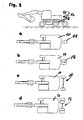
- FIG. 1 a mobile excavator 10 is shown schematically. On the undercarriage 12 of the wheeled excavator 10, two axle lines 14 and 16 are provided.
- trolley or Dollys 18 are shown, which can be exemplarily connected to the undercarriage 12 here.
- the type of connection between the trolley 18 and the wheeled excavator 10 is not shown here in detail.
- the trolley can be flange-mounted torque-resistant. The trolley engages the undercarriage 12.
- FIG. 1a a simple version is shown, in which by means of the trolley 18, an axle line is shown with a centrally located wheel with single tires.
- FIG. 1b a trolley with centrally arranged axle line is shown with twin tires, wherein in the illustration according to FIG. 1b Also shown at the front end of the undercarriage additional second trolley 20 is shown with twin tires.
- the wheeled excavator is according to FIG. 1b equipped with four axle lines.
- the attached trolley 18 is equipped with two axle lines, which is flanged on the rear of the undercarriage 12 of the wheeled excavator. So here are four axle lines realized.
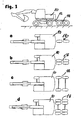
- FIG. 2 are variants of a wheeled excavator according to FIG. 1a shown in plan view.
- the wheeled excavator 10 is shown with undercarriage 12 and a rear of the undercarriage 12 mounted trolley 18 with an axis line in different variants.
- the axle line has a central single tire.
- the axle line has a central twin tire.
- the axis line of the additional trolley 18 has an eccentric arrangement of two single tires and in the illustration according to the Figure 2d the axis line has an eccentric arrangement of two twin axes.
- FIG. 3 a wheeled excavator 10 is shown with undercarriage 12, on which at the rear of the undercarriage 12, a trolley 18 is arranged with two axle lines.
- a trolley 18 shown with two consecutively centrally arranged single tires.
- FIG. 3b are here instead of the single tires of the FIG. 3a provided centrally arranged twin tires on the two axle lines.
- FIG. 3c are each two eccentrically arranged single tires and in the 3d figure each provided two eccentrically arranged twin tires.
- FIGS. 1 to 3 show here only some variants of the possible mounting versions for trolley in the context of the present invention.
Landscapes
- Engineering & Computer Science (AREA)
- Mining & Mineral Resources (AREA)
- Civil Engineering (AREA)
- General Engineering & Computer Science (AREA)
- Structural Engineering (AREA)
- Handcart (AREA)
- Tires In General (AREA)
- Earth Drilling (AREA)
- Turbine Rotor Nozzle Sealing (AREA)
- Shovels (AREA)
Description
- Die Erfindung betrifft einen Mobilbagger mit einem Unterwagen mit mindestens zwei Achsen.
- Mobilbagger sind als Radfahrzeug ausgestattet und weisen in der Regel zwei Achsen auf. Damit sind sie straßentauglich und können unabhängig und eigenständig zu ihrem Einsatzort fahren.
- In Deutschland ist im Rahmen der Straßenverkehrsordnung allerdings die Achslast von Mobilbaggern zur Erlangung einer uneingeschränkten - das heißt nicht strekkengebundenen - Fahrerlaubnis beschränkt. Bei angetriebenen Achsen ist die maximale Achslast derzeit 11,5 t und bei nicht angetriebenen Achsen 10 t. Das maximal zulässige Baggergewicht für Straßenfahrten ist bei zwei Achsen auf 18 t begrenzt.
- Aus der
DE27 25 357 A1 ist ein Mobilbagger mit den Merkmalen des Oberbegriffs des Anspruch 1 bereits bekannt. - Aufgabe der Erfindung ist es, einen Mobilbagger zu schaffen, der auch bei höherem Eigengewicht grundsätzlich zur Straßenfahrt auf öffentlichen Verkehrswegen zugelassen werden kann.
- Erfindungsgemäß wird diese Aufgabe durch die Merkmale des Anspruchs 1 gelöst. Hier ist entsprechend der Lösung am Mobilbagger (Unterwagen) mindestens ein Rollwagen bzw. Dolly momentensteif angeflanscht und/oder koppelbar. Dieser Rollwagen bzw. Dolly weist mindestens eine weitere Achse auf, so daß neben den zwei Achslinien des üblichen Mobilbaggers zumindest eine oder beliebig mehrere Achslinien über den fest mit dem Mobilbagger verbundenen Rollwagen bzw. Dolly hinzutreten. Je nach Anzahl der somit neu geschaffenen Achslinien kann der Mobilbagger mit einem Gesamtgewicht über 18 t auf öffentlichen Verkehrswegen betrieben werden.
- Es wird somit eine feste Verbindung zwischen dem Mobilbagger und dem Rollwagen erzeugt, so daß sich hier die Last des Mobilbaggers in gleicher Weise auf die entsprechend zur Verfügung gestellten Achsen des Unterwagens bzw. Rollwagens verteilt. Nach dem entsprechenden Straßentransport kann der koppelbare Rollwagen für den Einsatz auf der Baustelle entfernt werden, um für den nächsten Straßentransport wieder angeflanscht zu werden.
- Besonders vorteilhafte Ausgestaltungen der Erfindung ergeben sich aus den sich an den Hauptanspruch anschließenden Unteransprüchen.
- Der mindestens eine Rollwagen kann an beliebiger Stelle des Mobilbaggers angeordnet sein. So kann er vorne am Unterwagen angeordnet sein, hinten am Unterwagen, an einer oder beiden Seiten des Unterwagens und/oder unterhalb des Unterwagens angeordnet und mit diesem befestigt sein. Selbstverständlich können mehrere Rollwagen gleichzeitig am Unterwagen im Rahmen der Erfindung befestigt sein, um eine optimierte Achslastverteilung zu erzielen.
- Im Rahmen der Erfindung kann der Rollwagen vorteilhaft mindestens eine mittig angeordnete Achslinie mit Singlebereifung oder Zwillingsbereifung aufweisen.
- Alternativ kann der Rollwagen mindestens eine Achslinie mit zwei außermittig angeordneten Single- oder Zwillingsreifen aufweisen. Bei größeren angebauten Rollwagen können die am Rollwagen angeordneten Räder mit einer Bremse ausgestattet sein. Die am Rollwagen angeordneten Räder können auch lenkbar sein. Schließlich können die am Rollwagen angeordneten Räder gefedert aufgehängt sein.
- Weiter kann die am Rollwagen angeordnete Achse(n) liftbar sein.
- Besonders vorteilhaft ist auf dem mindestens einen Rollwagen zusätzlich eine Aufnahmeeinrichtung zur Aufnahme und zum Transport von Anbaugeräten, Werkzeugen und dergleichen vorhanden.
- Weiter kann eine Aufnahmevorrichtung (Bügel oder Gegenstück zum Schnellwechseladapter) für ein besseres Handling angebracht sein.
- Gemäß einer weiteren vorteilhaften Ausbildung der Erfindung kann der mindestens eine Rollwagen über andere Anbauteile, wie beispielsweise das Stützschild, mit dem Unterwagen verbunden sein.
- Weitere Einzelheiten und Vorteile der Erfindung ergeben sich aus einem in der Zeichnung dargestellten Ausführungsbeispiel. Es zeigen:
- Figur 1:
- eine schematische Seitenansicht eines Mobilbaggers mit verschiedenen Anbauversionen eines Rollwagens, wobei die Anzahl der am Unterwagen gekoppelten Achslinien schematisch dargestellt sind,
- Figur 2:
- eine Darstellung, in der die verschiedenen Anbauversionen schematisch von oben gezeigt sind, wobei einige mögliche Achsausführungen für einen 1-achsigen am Unterwagen gekoppelten Rollwagen dargestellt sind und die
- Figur 3:
- andere Ausführungsvarianten eines erfindungsgemäßen Mobilbaggers, wobei exemplarisch einige Achsausführungen für einen 2-achsigen Rollwagen am Unterwagen gekoppelt sind.
- In der
Figur 1 ist ein Mobilbagger 10 schematisch dargestellt. Am Unterwagen 12 des Mobilbaggers 10 sind zwei Achslinien 14 und 16 vorgesehen. - In den Darstellungen der
Figur 1 a, b, c und d sind unterschiedliche Ausführungen von Rollwagen bzw. Dollys 18 gezeigt, die hier exemplarisch mit dem Unterwagen 12 verbunden werden können. Die Art der Verbindung zwischen dem Rollwagen 18 und dem Mobilbagger 10 ist hier nicht im einzelnen dargestellt. Grundsätzlich kann der Rollwagen momentensteif angeflanscht sein. Der Rollwagen greift am Unterwagen 12 an. - In der
Figur 1a ist eine einfache Version dargestellt, in der mittels des Rollwagens 18 eine Achslinie mit einem mittig angeordneten Rad mit Singlebereifung dargestellt ist. In der Ausführungsvariante gemäßFigur 1b ist ein Rollwagen mit mittig angeordneter Achslinie mit Zwillingsbereifung gezeigt, wobei in der Darstellung gemäßFigur 1b auch ein am vorderen Ende des Unterwagens angeordneter zusätzlicher zweiter Rollwagen 20 mit Zwillingsbereifung dargestellt ist. Somit ist der Mobilbagger gemäßFigur 1b mit vier Achslinien ausgestattet. - In der Darstellung gemäß
Figur 1c ist der angebaute Rollwagen 18 mit zwei Achslinien ausgestattet, wobei dieser hinten am Unterwagen 12 des Mobilbaggers angeflanscht ist. Hier sind also vier Achslinien realisiert. - In der Ausgestaltung gemäß
Figur 1d ist zusätzlich zu einer Anordnung eines Rollwagens 18 mit zwei Achslinien noch ein Rollwagen mit einer Achslinie im vorderen Teil des Unterwagens angeordnet. - In
Figur 2 sind Varianten eines Mobilbaggers gemäßFigur 1a in Draufsicht dargestellt. Hier ist der Mobilbagger 10 mit Unterwagen 12 und einem hinten am Unterwagen 12 angeflanschte Rollwagen 18 mit einer Achslinie in unterschiedlichen Varianten dargestellt. In derFigur 2a weist die Achslinie eine mittige Singlebereifung auf. In der Darstellung gemäßFigur 2b weist die Achslinie eine mittige Zwillingsbereifung auf. In der Darstellung gemäß derFigur 2c weist die Achslinie des zusätzlichen Rollwagens 18 eine außermittige Anordnung von zwei Singlereifen auf und in der Darstellung gemäß derFigur 2d weist die Achslinie eine außermittige Anordnung zweier Zwillingsachsen auf. - In der
Figur 3 ist ein Mobilbagger 10 mit Unterwagen 12 dargestellt, an welchem am hinteren Teil des Unterwagens 12 ein Rollwagen 18 mit zwei Achslinien angeordnet ist. Hier ist wiederum in derFigur 3a ein Rollwagen 18 mit zwei hintereinander mittig angeordneten Singlebereifungen dargestellt. In derFigur 3b sind hier statt der Singlebereifung derFigur 3a mittig angeordnete Zwillingsreifen auf den beiden Achslinien vorgesehen. In derFigur 3c sind jeweils zwei außermittig angeordnete Singlereifen und in derFigur 3d jeweils zwei außermittig angeordnete Zwillingsreifen vorgesehen. - Die
Figuren 1 bis 3 zeigen hier nur einige Varianten der möglichen Anbauversionen für Rollwagen im Rahmen der vorliegenden Erfindung.
Claims (7)
- Mobilbagger (10) mit einem Unterwagen (12) mit mindestens zwei Achsen (14, 16),
dadurch gekennzeichnet,
dass am Unterwagen (12) mindestens ein Rollwagen (18) durch ein momentensteifes Anflanschen derart koppelbar befestigt ist, dass sich die Last des Mobilbaggers (10) in gleicher Weise auf die entsprechend zur Verfügung gestellten Achsen des Unterwagens (12) und des Rollwagens (18) verteilt. - Mobilbagger nach Anspruch 1, dadurch gekennzeichnet, dass der mindestens eine Rollwagen (18) vorne, hinten, an einer oder beiden Seiten und/oder unter dem Mobilbagger (10) angeordnet ist.
- Mobilbagger nach einem der Ansprüche 1 bis 2, dadurch gekennzeichnet, dass der Rollwagen (18) mindestens eine mittig angeordnete Achslinie mit Singlebereifung oder Zwillingsbereifung aufweist.
- Mobilbagger nach einem der vorausgehenden Ansprüche, dadurch gekennzeichnet, dass der Rollwagen (18) mindestens eine Achslinie mit zwei außermittig angeordneten Single- oder Zwillingsreifen aufweist.
- Mobilbagger nach einem der vorausgehenden Ansprüche, dadurch gekennzeichnet, dass die am Rollwagen (18) angeordneten Räder mit einer Bremse ausgestattet sind.
- Mobilbagger nach einem der vorausgehenden Ansprüche, dadurch gekennzeichnet, dass die am Rollwagen (18) angeordneten Räder oder Achsen gefedert sind.
- Mobilbagger nach einem der vorausgehenden Ansprüche dadurch gekennzeichnet, dass auf dem mindestens einen Rollwagen (18) zusätzlich eine Aufnahmeeinrichtung zur Aufnahme und zum Transport von Anbaugeräten, Werkzeugen und dergleichen vorhanden sind.
Applications Claiming Priority (1)
| Application Number | Priority Date | Filing Date | Title |
|---|---|---|---|
| DE202004011368U DE202004011368U1 (de) | 2004-07-20 | 2004-07-20 | Mobilbagger |
Publications (2)
| Publication Number | Publication Date |
|---|---|
| EP1619314A1 EP1619314A1 (de) | 2006-01-25 |
| EP1619314B1 true EP1619314B1 (de) | 2010-05-19 |
Family
ID=35115851
Family Applications (1)
| Application Number | Title | Priority Date | Filing Date |
|---|---|---|---|
| EP05015435A Expired - Lifetime EP1619314B1 (de) | 2004-07-20 | 2005-07-15 | Mobilbagger |
Country Status (5)
| Country | Link |
|---|---|
| US (1) | US20060021263A1 (de) |
| EP (1) | EP1619314B1 (de) |
| AT (1) | ATE468445T1 (de) |
| DE (2) | DE202004011368U1 (de) |
| ES (1) | ES2344352T3 (de) |
Families Citing this family (3)
| Publication number | Priority date | Publication date | Assignee | Title |
|---|---|---|---|---|
| DE202006019051U1 (de) | 2006-12-18 | 2008-04-30 | Liebherr-Hydraulikbagger Gmbh | Mobilbagger |
| SE541394C8 (en) * | 2017-12-22 | 2019-12-03 | Scania Cv Ab | Method and a control arrangement for controlling vehicle operation comprising axle load control of at least one vehicle during vehicle operation |
| DE102024117762A1 (de) * | 2024-06-24 | 2025-12-24 | Echle Hartstahl Gmbh | Mobilisiereinrichtung |
Family Cites Families (19)
| Publication number | Priority date | Publication date | Assignee | Title |
|---|---|---|---|---|
| US2698491A (en) * | 1949-11-18 | 1955-01-04 | George H Felt | Bulldozer blade stabilizing attachment |
| GB1459263A (en) * | 1973-11-28 | 1976-12-22 | Barko Hydraulics | Loader vehicle in combination with a steering unit |
| US4081090A (en) * | 1977-02-17 | 1978-03-28 | Hopkins David L | Implement transportation train |
| US4285627A (en) * | 1977-05-23 | 1981-08-25 | Standard Manufacturing Company, Incorporated | Undercarriage for adverse terrain vehicle |
| DE2725357A1 (de) | 1977-06-04 | 1978-12-07 | Fuchs Fa Johannes | Verfahrbare arbeitsmaschine |
| NO780692L (no) * | 1978-02-28 | 1979-08-29 | Braathen Thor F | Leddet, terrenggaaende motorkjoeretoey |
| US4360311A (en) * | 1979-10-22 | 1982-11-23 | Serge Dufour | Public works machine, such as a hydraulic self-propelled articulated shovel |
| US4392541A (en) * | 1981-05-01 | 1983-07-12 | Spyder Sales & Service, Inc. | Vehicle convertible from a tricycle two wheel drive to a four wheel four wheel drive |
| PT74697B (de) * | 1981-05-15 | 1983-10-25 | Menzi Ag Ernst | Bagger |
| US4501334A (en) * | 1983-07-07 | 1985-02-26 | Deere & Company | Wheeled excavator having a dozer blade and a boom-mounted stabilizer wheel |
| SE459017B (sv) * | 1984-05-18 | 1989-05-29 | Vreten Ab | Tillsatsredskap foer hjullastare och liknande maskiner |
| US4705133A (en) * | 1987-01-23 | 1987-11-10 | Mcneilus Truck And Manufacturing, Inc. | Tag axle assembly for work vehicle |
| US4826385A (en) * | 1987-10-27 | 1989-05-02 | Kr. Larsen Sveiseverksted A/S | Trailer |
| DE4028773C2 (de) * | 1989-09-28 | 1994-11-10 | Schaeff Karl Gmbh & Co | Schreitfahrzeug |
| US5335930A (en) * | 1992-12-04 | 1994-08-09 | Peter Tighe | Construction site hauling system |
| US5618155A (en) * | 1992-12-04 | 1997-04-08 | Tighe; Peter | Construction site hauling system |
| US5458355A (en) * | 1994-04-05 | 1995-10-17 | Young; Francis M. | Retractable double trailing axle attachment |
| US5498021A (en) * | 1995-03-16 | 1996-03-12 | Mcneilus Truck And Manufacturing Co. | Tag axle mounting system |
| US6439332B1 (en) * | 2001-07-13 | 2002-08-27 | Robert Meurer | Caster structure for attachment to a rear end of a skid-steer loader |
-
2004
- 2004-07-20 DE DE202004011368U patent/DE202004011368U1/de not_active Expired - Lifetime
-
2005
- 2005-07-15 AT AT05015435T patent/ATE468445T1/de active
- 2005-07-15 DE DE502005009584T patent/DE502005009584D1/de not_active Expired - Lifetime
- 2005-07-15 EP EP05015435A patent/EP1619314B1/de not_active Expired - Lifetime
- 2005-07-15 ES ES05015435T patent/ES2344352T3/es not_active Expired - Lifetime
- 2005-07-19 US US11/184,339 patent/US20060021263A1/en not_active Abandoned
Also Published As
| Publication number | Publication date |
|---|---|
| ES2344352T3 (es) | 2010-08-25 |
| EP1619314A1 (de) | 2006-01-25 |
| ATE468445T1 (de) | 2010-06-15 |
| US20060021263A1 (en) | 2006-02-02 |
| DE502005009584D1 (de) | 2010-07-01 |
| DE202004011368U1 (de) | 2005-12-08 |
Similar Documents
| Publication | Publication Date | Title |
|---|---|---|
| DE102013210044B4 (de) | Fahrzeug mit modularer Fahrvorrichtung | |
| EP1925754B1 (de) | Zweiwegebagger | |
| DE60104955T2 (de) | Rekonfigurierbarer Krantrager | |
| EP1340661B1 (de) | Angetriebenes Einzelradfahrwerk für ein Schienenfahrzeug, insbesondere niederfluriges Strassenbahnfahrzeug | |
| DE202004004714U1 (de) | Unterwagen für mobile Arbeitsmaschinen | |
| DE2156282B2 (de) | Maschine zum schichtweisen Abtragen von verschlissenen Straßendecken | |
| DE102012110441B4 (de) | Zweiwegefahrzeug | |
| EP1213206A3 (de) | Lenkvorrichtung für lenkbare Vorderräder | |
| EP1619314A1 (de) | Mobilbagger | |
| DE2905528C2 (de) | ||
| DE102008031056A1 (de) | Fahrwerk eines Fahrzeugs mit Querparkfunktion | |
| EP3412620B1 (de) | Aufbaukran und aufbaukransystem | |
| DE1114442B (de) | Fahrbares, als Loeffelbagger, Hackgeraet, Ramme od. dgl. verwendbares Geraet | |
| DE3034766A1 (de) | Regalstapelfahrzeug | |
| EP1209118A1 (de) | Untergestell und Fahrwerk für einen Unterwagen eines fahrbaren Arbeitsgerätes | |
| DE3806260A1 (de) | In verbindung mit eisenbahn-drehgestellen zu verwendende kupplungsvorrichtung nach art einer dynamischen kupplung | |
| DE10023219A1 (de) | Schienengeführter Schwerlasttransportwagen | |
| DE563500C (de) | Fahrbarer Kran | |
| DE2009645A1 (de) | Löffelbagger | |
| EP0827848B1 (de) | Fahrwerk für Kraftfahrzeuge oder Anhänger | |
| EP2059639A1 (de) | Mobilbagger | |
| AT407135B (de) | Schwerfahrzeug | |
| DE1163160B (de) | Gleisloses Flurfoerdergeraet | |
| DE2216307A1 (de) | Spurbreitenveraenderbares gleiskettenfahrzeug | |
| DE102024117762A1 (de) | Mobilisiereinrichtung |
Legal Events
| Date | Code | Title | Description |
|---|---|---|---|
| PUAI | Public reference made under article 153(3) epc to a published international application that has entered the european phase |
Free format text: ORIGINAL CODE: 0009012 |
|
| AK | Designated contracting states |
Kind code of ref document: A1 Designated state(s): AT BE BG CH CY CZ DE DK EE ES FI FR GB GR HU IE IS IT LI LT LU LV MC NL PL PT RO SE SI SK TR |
|
| AX | Request for extension of the european patent |
Extension state: AL BA HR MK YU |
|
| 17P | Request for examination filed |
Effective date: 20060518 |
|
| 17Q | First examination report despatched |
Effective date: 20060821 |
|
| AKX | Designation fees paid |
Designated state(s): AT BE BG CH CY CZ DE DK EE ES FI FR GB GR HU IE IS IT LI LT LU LV MC NL PL PT RO SE SI SK TR |
|
| GRAP | Despatch of communication of intention to grant a patent |
Free format text: ORIGINAL CODE: EPIDOSNIGR1 |
|
| GRAS | Grant fee paid |
Free format text: ORIGINAL CODE: EPIDOSNIGR3 |
|
| GRAA | (expected) grant |
Free format text: ORIGINAL CODE: 0009210 |
|
| AK | Designated contracting states |
Kind code of ref document: B1 Designated state(s): AT BE BG CH CY CZ DE DK EE ES FI FR GB GR HU IE IS IT LI LT LU LV MC NL PL PT RO SE SI SK TR |
|
| REG | Reference to a national code |
Ref country code: GB Ref legal event code: FG4D Free format text: NOT ENGLISH |
|
| REG | Reference to a national code |
Ref country code: CH Ref legal event code: EP Ref country code: CH Ref legal event code: NV Representative=s name: BOVARD AG PATENTANWAELTE |
|
| REG | Reference to a national code |
Ref country code: IE Ref legal event code: FG4D Free format text: LANGUAGE OF EP DOCUMENT: GERMAN |
|
| REF | Corresponds to: |
Ref document number: 502005009584 Country of ref document: DE Date of ref document: 20100701 Kind code of ref document: P |
|
| REG | Reference to a national code |
Ref country code: SE Ref legal event code: TRGR |
|
| REG | Reference to a national code |
Ref country code: ES Ref legal event code: FG2A Ref document number: 2344352 Country of ref document: ES Kind code of ref document: T3 |
|
| REG | Reference to a national code |
Ref country code: NL Ref legal event code: T3 |
|
| LTIE | Lt: invalidation of european patent or patent extension |
Effective date: 20100519 |
|
| PG25 | Lapsed in a contracting state [announced via postgrant information from national office to epo] |
Ref country code: LT Free format text: LAPSE BECAUSE OF FAILURE TO SUBMIT A TRANSLATION OF THE DESCRIPTION OR TO PAY THE FEE WITHIN THE PRESCRIBED TIME-LIMIT Effective date: 20100519 |
|
| PG25 | Lapsed in a contracting state [announced via postgrant information from national office to epo] |
Ref country code: SI Free format text: LAPSE BECAUSE OF FAILURE TO SUBMIT A TRANSLATION OF THE DESCRIPTION OR TO PAY THE FEE WITHIN THE PRESCRIBED TIME-LIMIT Effective date: 20100519 Ref country code: FI Free format text: LAPSE BECAUSE OF FAILURE TO SUBMIT A TRANSLATION OF THE DESCRIPTION OR TO PAY THE FEE WITHIN THE PRESCRIBED TIME-LIMIT Effective date: 20100519 Ref country code: IS Free format text: LAPSE BECAUSE OF FAILURE TO SUBMIT A TRANSLATION OF THE DESCRIPTION OR TO PAY THE FEE WITHIN THE PRESCRIBED TIME-LIMIT Effective date: 20100919 Ref country code: LV Free format text: LAPSE BECAUSE OF FAILURE TO SUBMIT A TRANSLATION OF THE DESCRIPTION OR TO PAY THE FEE WITHIN THE PRESCRIBED TIME-LIMIT Effective date: 20100519 |
|
| PG25 | Lapsed in a contracting state [announced via postgrant information from national office to epo] |
Ref country code: PL Free format text: LAPSE BECAUSE OF FAILURE TO SUBMIT A TRANSLATION OF THE DESCRIPTION OR TO PAY THE FEE WITHIN THE PRESCRIBED TIME-LIMIT Effective date: 20100519 Ref country code: GR Free format text: LAPSE BECAUSE OF FAILURE TO SUBMIT A TRANSLATION OF THE DESCRIPTION OR TO PAY THE FEE WITHIN THE PRESCRIBED TIME-LIMIT Effective date: 20100820 Ref country code: CY Free format text: LAPSE BECAUSE OF FAILURE TO SUBMIT A TRANSLATION OF THE DESCRIPTION OR TO PAY THE FEE WITHIN THE PRESCRIBED TIME-LIMIT Effective date: 20100519 |
|
| REG | Reference to a national code |
Ref country code: IE Ref legal event code: FD4D |
|
| PG25 | Lapsed in a contracting state [announced via postgrant information from national office to epo] |
Ref country code: DK Free format text: LAPSE BECAUSE OF FAILURE TO SUBMIT A TRANSLATION OF THE DESCRIPTION OR TO PAY THE FEE WITHIN THE PRESCRIBED TIME-LIMIT Effective date: 20100519 Ref country code: PT Free format text: LAPSE BECAUSE OF FAILURE TO SUBMIT A TRANSLATION OF THE DESCRIPTION OR TO PAY THE FEE WITHIN THE PRESCRIBED TIME-LIMIT Effective date: 20100920 Ref country code: IE Free format text: LAPSE BECAUSE OF FAILURE TO SUBMIT A TRANSLATION OF THE DESCRIPTION OR TO PAY THE FEE WITHIN THE PRESCRIBED TIME-LIMIT Effective date: 20100519 Ref country code: EE Free format text: LAPSE BECAUSE OF FAILURE TO SUBMIT A TRANSLATION OF THE DESCRIPTION OR TO PAY THE FEE WITHIN THE PRESCRIBED TIME-LIMIT Effective date: 20100519 |
|
| PG25 | Lapsed in a contracting state [announced via postgrant information from national office to epo] |
Ref country code: CZ Free format text: LAPSE BECAUSE OF FAILURE TO SUBMIT A TRANSLATION OF THE DESCRIPTION OR TO PAY THE FEE WITHIN THE PRESCRIBED TIME-LIMIT Effective date: 20100519 Ref country code: RO Free format text: LAPSE BECAUSE OF FAILURE TO SUBMIT A TRANSLATION OF THE DESCRIPTION OR TO PAY THE FEE WITHIN THE PRESCRIBED TIME-LIMIT Effective date: 20100519 Ref country code: MC Free format text: LAPSE BECAUSE OF NON-PAYMENT OF DUE FEES Effective date: 20100731 Ref country code: SK Free format text: LAPSE BECAUSE OF FAILURE TO SUBMIT A TRANSLATION OF THE DESCRIPTION OR TO PAY THE FEE WITHIN THE PRESCRIBED TIME-LIMIT Effective date: 20100519 |
|
| PLBE | No opposition filed within time limit |
Free format text: ORIGINAL CODE: 0009261 |
|
| STAA | Information on the status of an ep patent application or granted ep patent |
Free format text: STATUS: NO OPPOSITION FILED WITHIN TIME LIMIT |
|
| REG | Reference to a national code |
Ref country code: CH Ref legal event code: PFA Owner name: LIEBHERR-HYDRAULIKBAGGER GMBH Free format text: LIEBHERR-HYDRAULIKBAGGER GMBH#LIEBHERRSTRASSE 12#88457 KIRCHDORF/ILLER (DE) -TRANSFER TO- LIEBHERR-HYDRAULIKBAGGER GMBH#LIEBHERRSTRASSE 12#88457 KIRCHDORF/ILLER (DE) |
|
| 26N | No opposition filed |
Effective date: 20110222 |
|
| REG | Reference to a national code |
Ref country code: DE Ref legal event code: R097 Ref document number: 502005009584 Country of ref document: DE Effective date: 20110221 |
|
| PG25 | Lapsed in a contracting state [announced via postgrant information from national office to epo] |
Ref country code: BG Free format text: LAPSE BECAUSE OF FAILURE TO SUBMIT A TRANSLATION OF THE DESCRIPTION OR TO PAY THE FEE WITHIN THE PRESCRIBED TIME-LIMIT Effective date: 20100519 Ref country code: HU Free format text: LAPSE BECAUSE OF FAILURE TO SUBMIT A TRANSLATION OF THE DESCRIPTION OR TO PAY THE FEE WITHIN THE PRESCRIBED TIME-LIMIT Effective date: 20101120 Ref country code: LU Free format text: LAPSE BECAUSE OF NON-PAYMENT OF DUE FEES Effective date: 20100715 |
|
| PG25 | Lapsed in a contracting state [announced via postgrant information from national office to epo] |
Ref country code: TR Free format text: LAPSE BECAUSE OF FAILURE TO SUBMIT A TRANSLATION OF THE DESCRIPTION OR TO PAY THE FEE WITHIN THE PRESCRIBED TIME-LIMIT Effective date: 20100519 |
|
| PG25 | Lapsed in a contracting state [announced via postgrant information from national office to epo] |
Ref country code: BG Free format text: LAPSE BECAUSE OF FAILURE TO SUBMIT A TRANSLATION OF THE DESCRIPTION OR TO PAY THE FEE WITHIN THE PRESCRIBED TIME-LIMIT Effective date: 20100819 |
|
| REG | Reference to a national code |
Ref country code: FR Ref legal event code: PLFP Year of fee payment: 12 |
|
| REG | Reference to a national code |
Ref country code: FR Ref legal event code: PLFP Year of fee payment: 13 |
|
| REG | Reference to a national code |
Ref country code: FR Ref legal event code: PLFP Year of fee payment: 14 |
|
| P01 | Opt-out of the competence of the unified patent court (upc) registered |
Effective date: 20230607 |
|
| PGFP | Annual fee paid to national office [announced via postgrant information from national office to epo] |
Ref country code: NL Payment date: 20230724 Year of fee payment: 19 |
|
| PGFP | Annual fee paid to national office [announced via postgrant information from national office to epo] |
Ref country code: IT Payment date: 20230727 Year of fee payment: 19 Ref country code: GB Payment date: 20230720 Year of fee payment: 19 Ref country code: ES Payment date: 20230801 Year of fee payment: 19 Ref country code: CH Payment date: 20230801 Year of fee payment: 19 Ref country code: AT Payment date: 20230719 Year of fee payment: 19 |
|
| PGFP | Annual fee paid to national office [announced via postgrant information from national office to epo] |
Ref country code: SE Payment date: 20230721 Year of fee payment: 19 Ref country code: FR Payment date: 20230721 Year of fee payment: 19 Ref country code: DE Payment date: 20230724 Year of fee payment: 19 Ref country code: BE Payment date: 20230720 Year of fee payment: 19 |
|
| REG | Reference to a national code |
Ref country code: DE Ref legal event code: R119 Ref document number: 502005009584 Country of ref document: DE |
|
| REG | Reference to a national code |
Ref country code: CH Ref legal event code: PL |
|
| REG | Reference to a national code |
Ref country code: SE Ref legal event code: EUG |
|
| REG | Reference to a national code |
Ref country code: NL Ref legal event code: MM Effective date: 20240801 |
|
| REG | Reference to a national code |
Ref country code: AT Ref legal event code: MM01 Ref document number: 468445 Country of ref document: AT Kind code of ref document: T Effective date: 20240715 |
|
| GBPC | Gb: european patent ceased through non-payment of renewal fee |
Effective date: 20240715 |
|
| PG25 | Lapsed in a contracting state [announced via postgrant information from national office to epo] |
Ref country code: DE Free format text: LAPSE BECAUSE OF NON-PAYMENT OF DUE FEES Effective date: 20250201 |
|
| PG25 | Lapsed in a contracting state [announced via postgrant information from national office to epo] |
Ref country code: NL Free format text: LAPSE BECAUSE OF NON-PAYMENT OF DUE FEES Effective date: 20240801 |
|
| PG25 | Lapsed in a contracting state [announced via postgrant information from national office to epo] |
Ref country code: AT Free format text: LAPSE BECAUSE OF NON-PAYMENT OF DUE FEES Effective date: 20240715 Ref country code: CH Free format text: LAPSE BECAUSE OF NON-PAYMENT OF DUE FEES Effective date: 20240731 Ref country code: BE Free format text: LAPSE BECAUSE OF NON-PAYMENT OF DUE FEES Effective date: 20240731 |
|
| PG25 | Lapsed in a contracting state [announced via postgrant information from national office to epo] |
Ref country code: FR Free format text: LAPSE BECAUSE OF NON-PAYMENT OF DUE FEES Effective date: 20240731 |
|
| PG25 | Lapsed in a contracting state [announced via postgrant information from national office to epo] |
Ref country code: GB Free format text: LAPSE BECAUSE OF NON-PAYMENT OF DUE FEES Effective date: 20240715 |
|
| REG | Reference to a national code |
Ref country code: BE Ref legal event code: MM Effective date: 20240731 |
|
| PG25 | Lapsed in a contracting state [announced via postgrant information from national office to epo] |
Ref country code: IT Free format text: LAPSE BECAUSE OF NON-PAYMENT OF DUE FEES Effective date: 20240715 |
|
| REG | Reference to a national code |
Ref country code: ES Ref legal event code: FD2A Effective date: 20250829 |
|
| PG25 | Lapsed in a contracting state [announced via postgrant information from national office to epo] |
Ref country code: ES Free format text: LAPSE BECAUSE OF NON-PAYMENT OF DUE FEES Effective date: 20240716 |
|
| PG25 | Lapsed in a contracting state [announced via postgrant information from national office to epo] |
Ref country code: SE Free format text: LAPSE BECAUSE OF NON-PAYMENT OF DUE FEES Effective date: 20240716 |